MOJIX CBLENODE3K Star 3000 System User Manual USERMANUAL STAR3000 2 0 1x
MOJIX, Inc. Star 3000 System USERMANUAL STAR3000 2 0 1x
MOJIX >
Contents
- 1. Users Manual Part 1
- 2. Users Manual Part 2
- 3. Users Manual Part 3
- 4. Users Manual Part 4
- 5. Users Manual Part 5
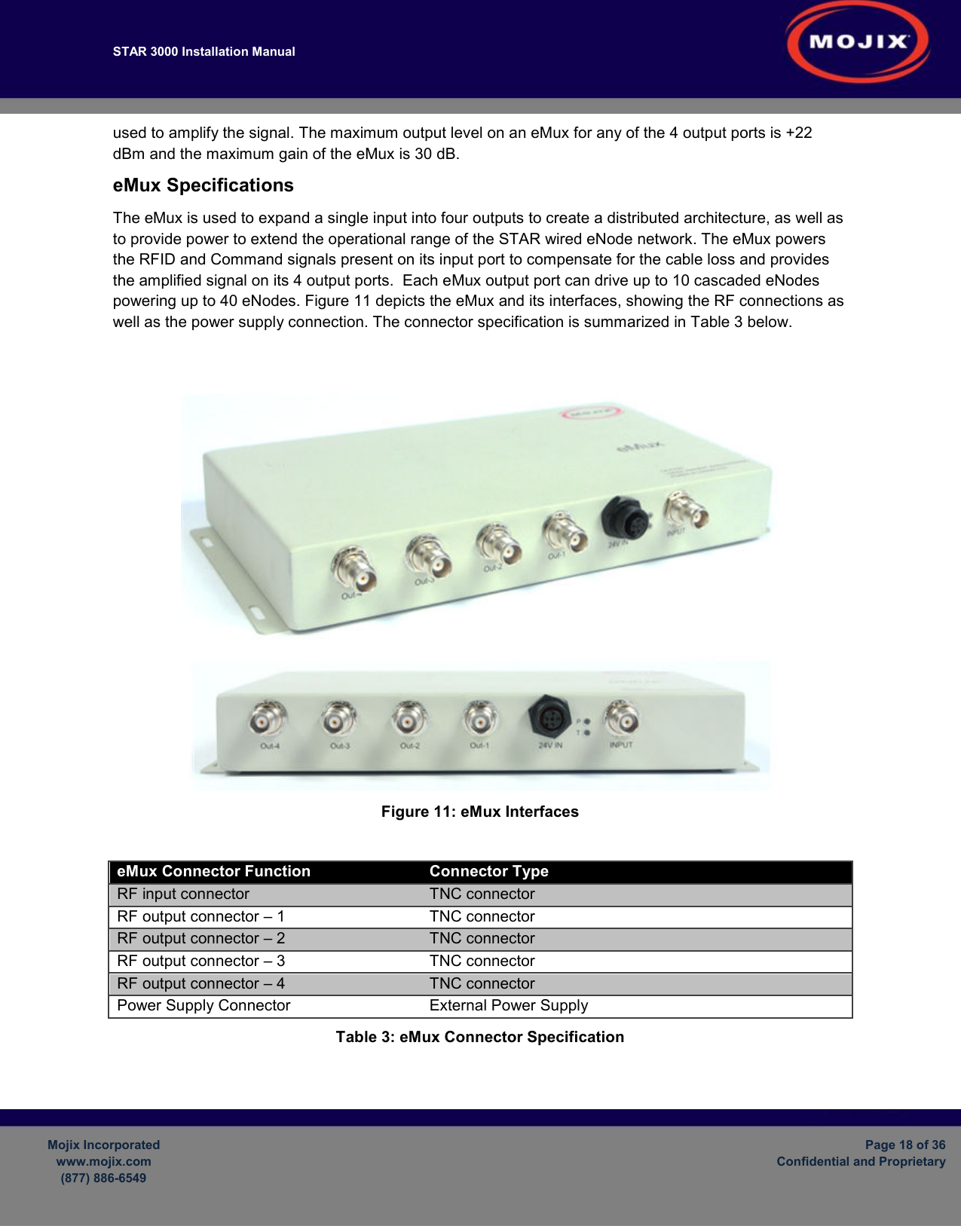
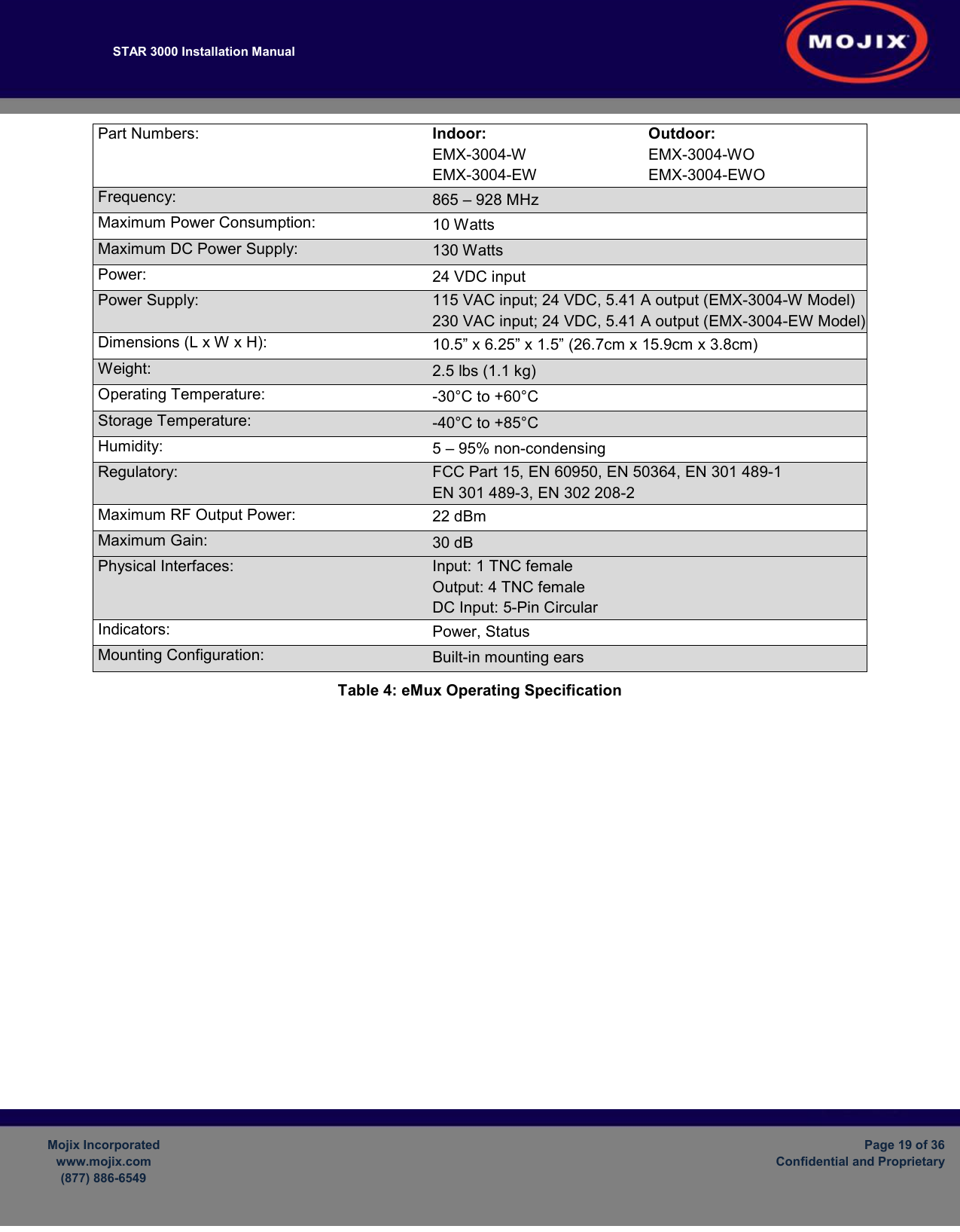
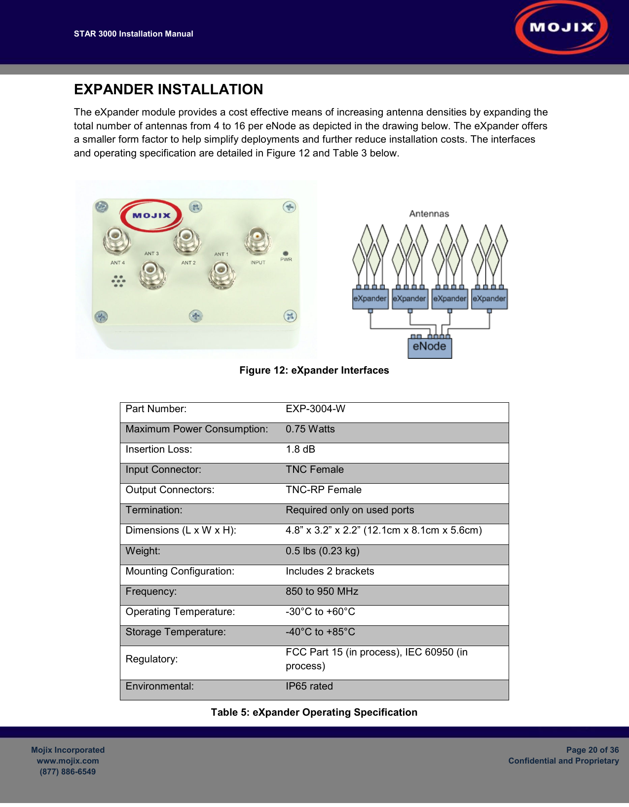
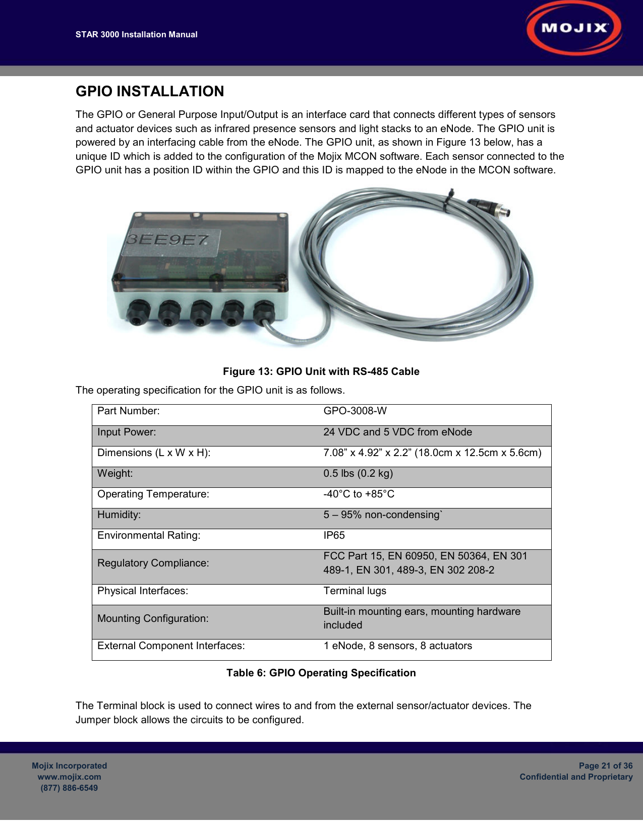
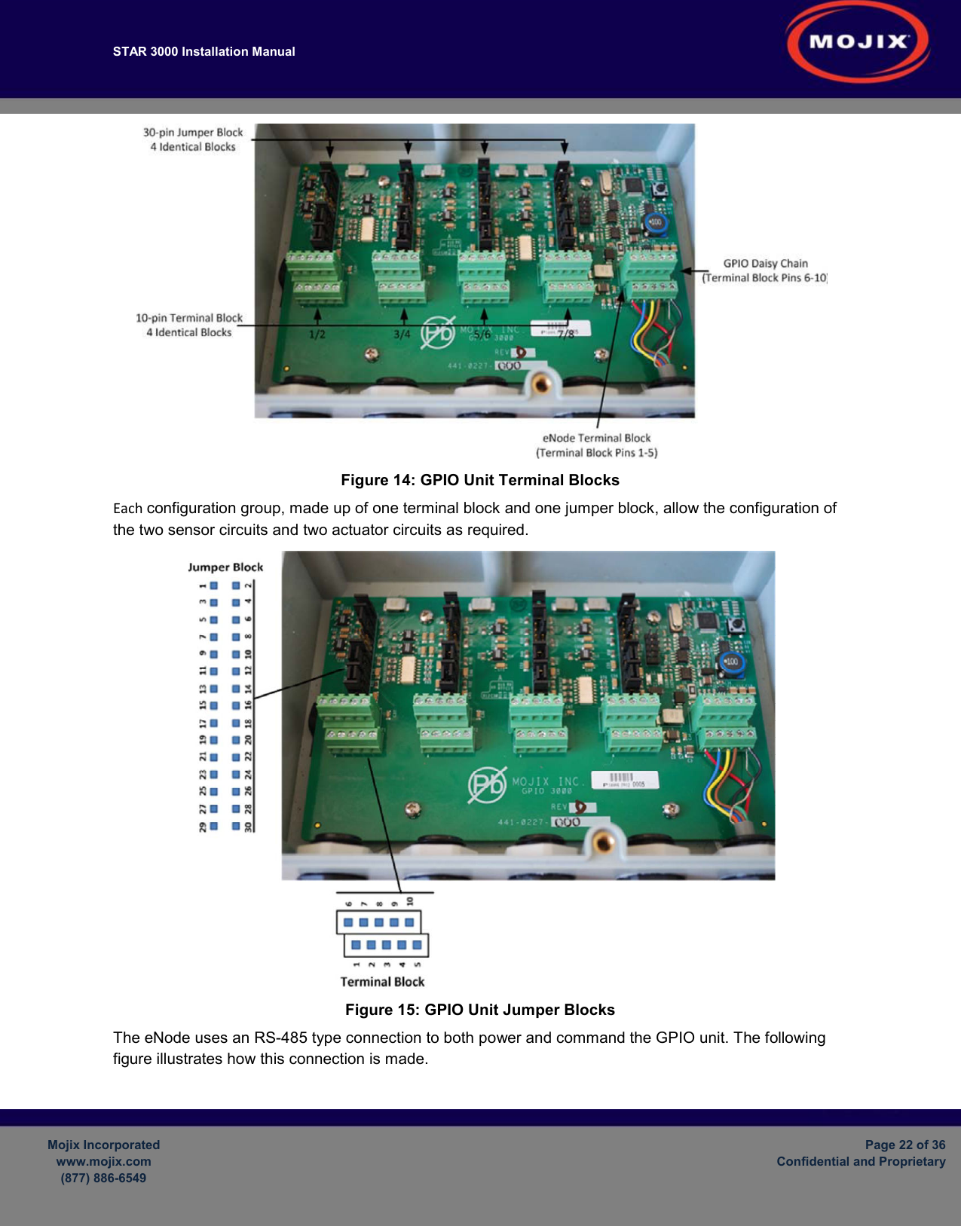
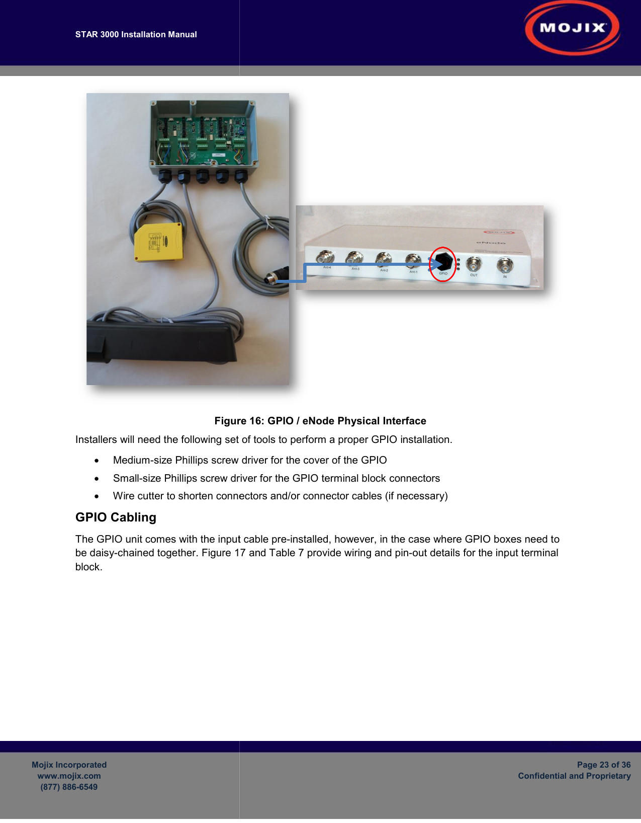
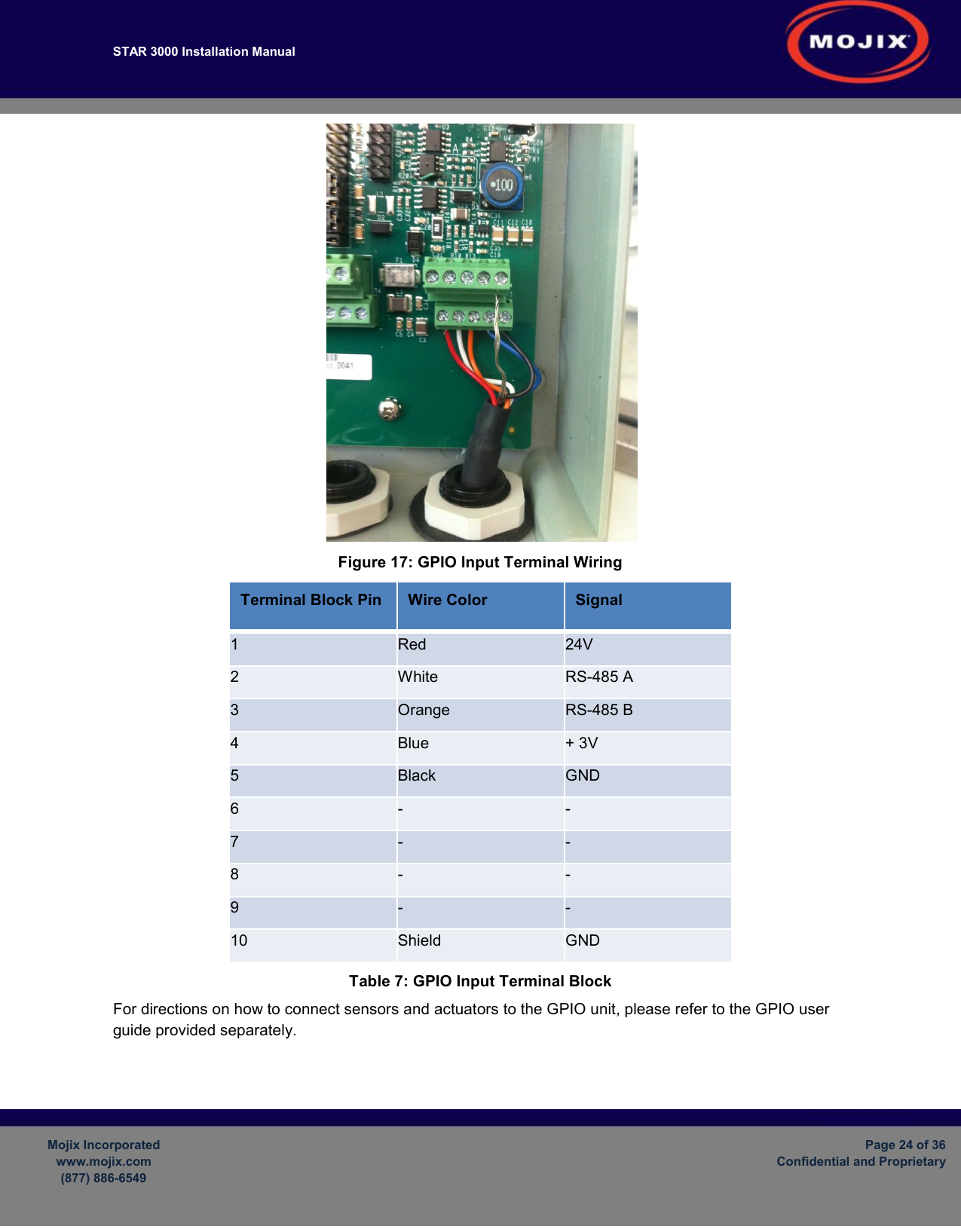
Users Manual Part 4