MOJIX CBLENODE3K Star 3000 System User Manual USERMANUAL STAR3000 2 0 1x
MOJIX, Inc. Star 3000 System USERMANUAL STAR3000 2 0 1x
MOJIX >
Contents
- 1. Users Manual Part 1
- 2. Users Manual Part 2
- 3. Users Manual Part 3
- 4. Users Manual Part 4
- 5. Users Manual Part 5
Users Manual Part 4
STAR 3000 Installation Manual
Mojix Incorporated
www.mojix.com
(877) 886-6549
Page
13
of
36
Confidential and Proprietary
STAR POWER SUPPLY INSTALLATION
Recommended installation of the power supply is a wall mounted configuration within 20 feet from the
STAR Receiver.
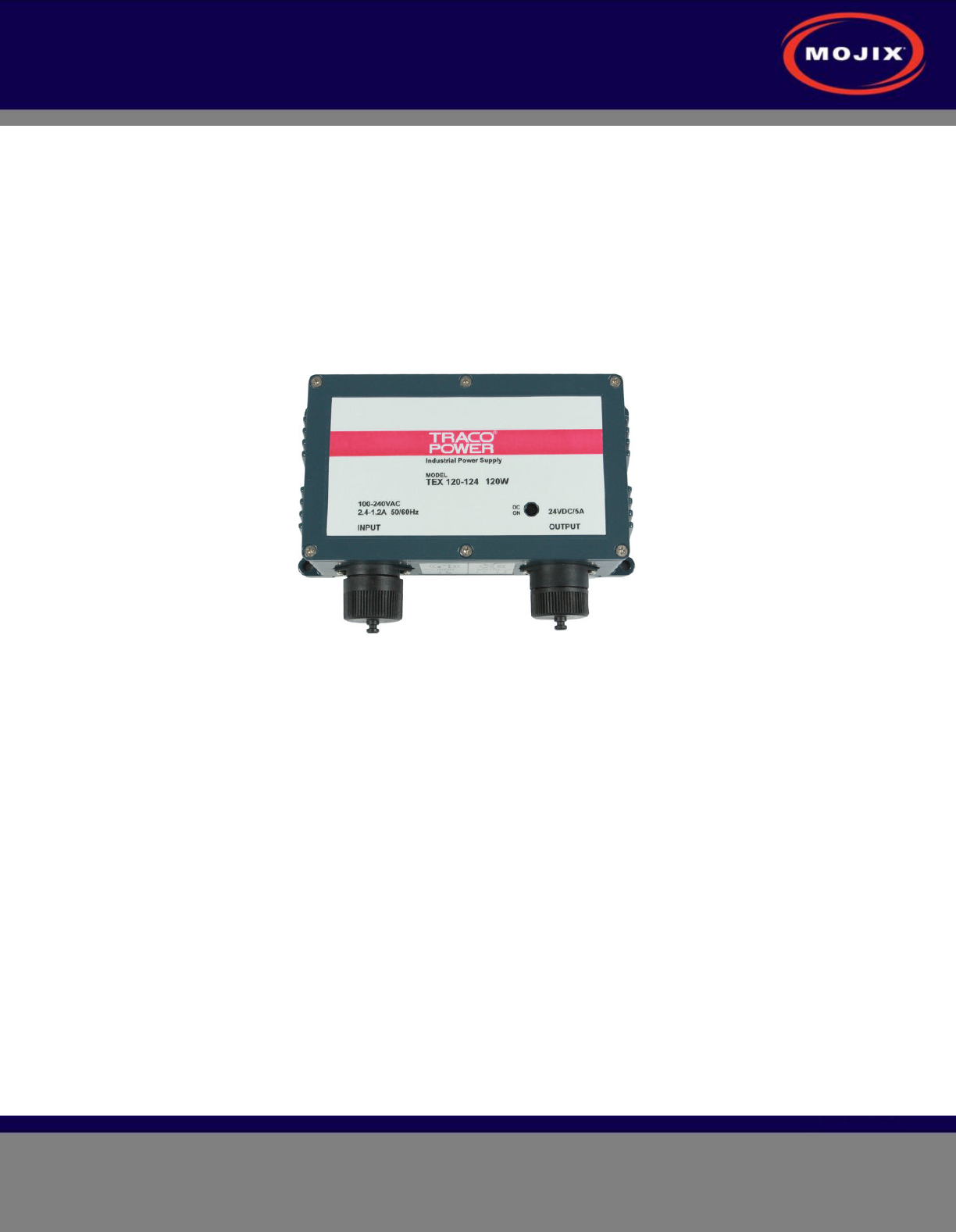
Wall Mount Power Supply
Figure 8 shows the power supply with integrated mounting brackets.
Figure 8: STAR Power Supply
The wall mounted power supply requires the following hardware (not included with shipment).
• #6 Drywall (bugle head) or #6 wood screws if the unit is being fastened to a wooden surface
• For a solid wood mount, box nails are a suitable option, provided that the head diameter is more
than .28” and less than .30” in diameter and the shank of the nail is at least 2” long.
• For a metal surface mount that is at least .1875” thick, #6-32 pan head machine screws may be
used.
• For drywall/plaster fastening, 1/8 Molly or Toggle bolts must be used.
The recommended mounting procedure is:
1. For drywall mounts, "Molly Bolts" are preferred. Alternatively, toggle bolts are a suitable option, as
they offer a pull-down force more than 4X the industry standard, and are highly recommended in
areas prone to seismic activity.
2. Alternatively for drywall mounts, Bugle-head #6 Drywall screws (coarse thread) are also acceptable, if
all 4 tie-down points are used, offering an industry standard of a pull-down strength of at least 4X the
weight of the unit.

STAR 3000 Installation Manual
Mojix Incorporated
www.mojix.com
(877) 886-6549
Page
14
of
36
Confidential and Proprietary
3. If the wall thickness is at least 1/2" wood (plywood, for example), nails can also be used.
Cables must be properly dressed and supported. Both AC and DC cables should be routed with a service
loop and must be supported at least once within 18” of the power supply unit. Cables can be run in
conduit, providing (a) the conduit is not hanging on the cables, (b) the service loop exists, and (c) there is
at least one support/tie-down on the cables between conduit and power supply.
STAR 3000 Installation Manual
Mojix Incorporated
www.mojix.com
(877) 886-6549
Page
15
of
36
Confidential and Proprietary
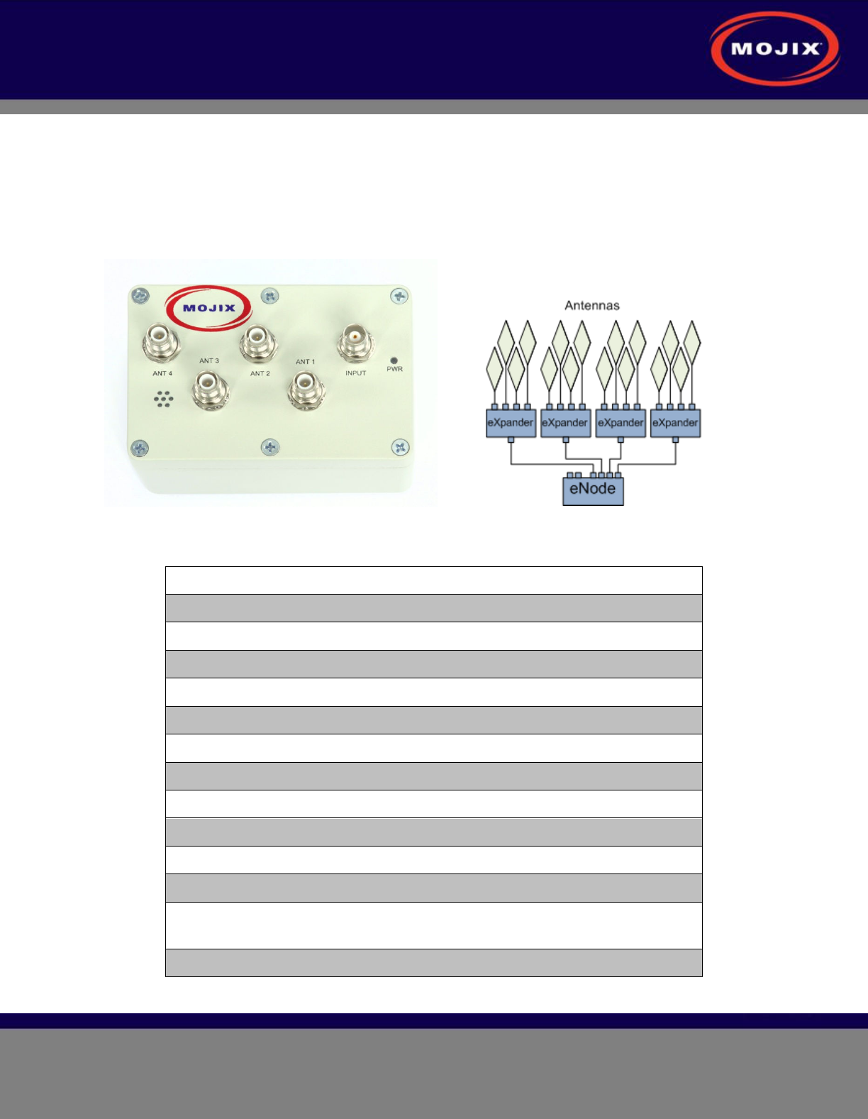
ENODE INSTALLATION
The Mojix eNodes (exciter Node) are the building blocks of the Mojix STAR system, defining multiple
RFID coverage areas and interrogation zones configured to support each unique business process. Mojix
provides a full range of eNode models from wired to wireless, certified in multiple regions and across
multiple frequency bands.
The Mojix eNodes are reliable, autonomously operated simple RF transmitters, designed to excite all
types of EPC UHF Gen 2 RFID tags within their designated RFID coverage areas. The eNode connects
to four RFID antennas that are controlled by the STAR to energize RFID tags. The network of eNodes is
connected through a distributed architecture to a STAR unit via an eMux using coaxial cable. Each eNode
can service up to either four connected antennas or four eXpander modules with up to sixteen antennas,
using low-loss cables up to a distance of 50 feet.
eNode Specifications
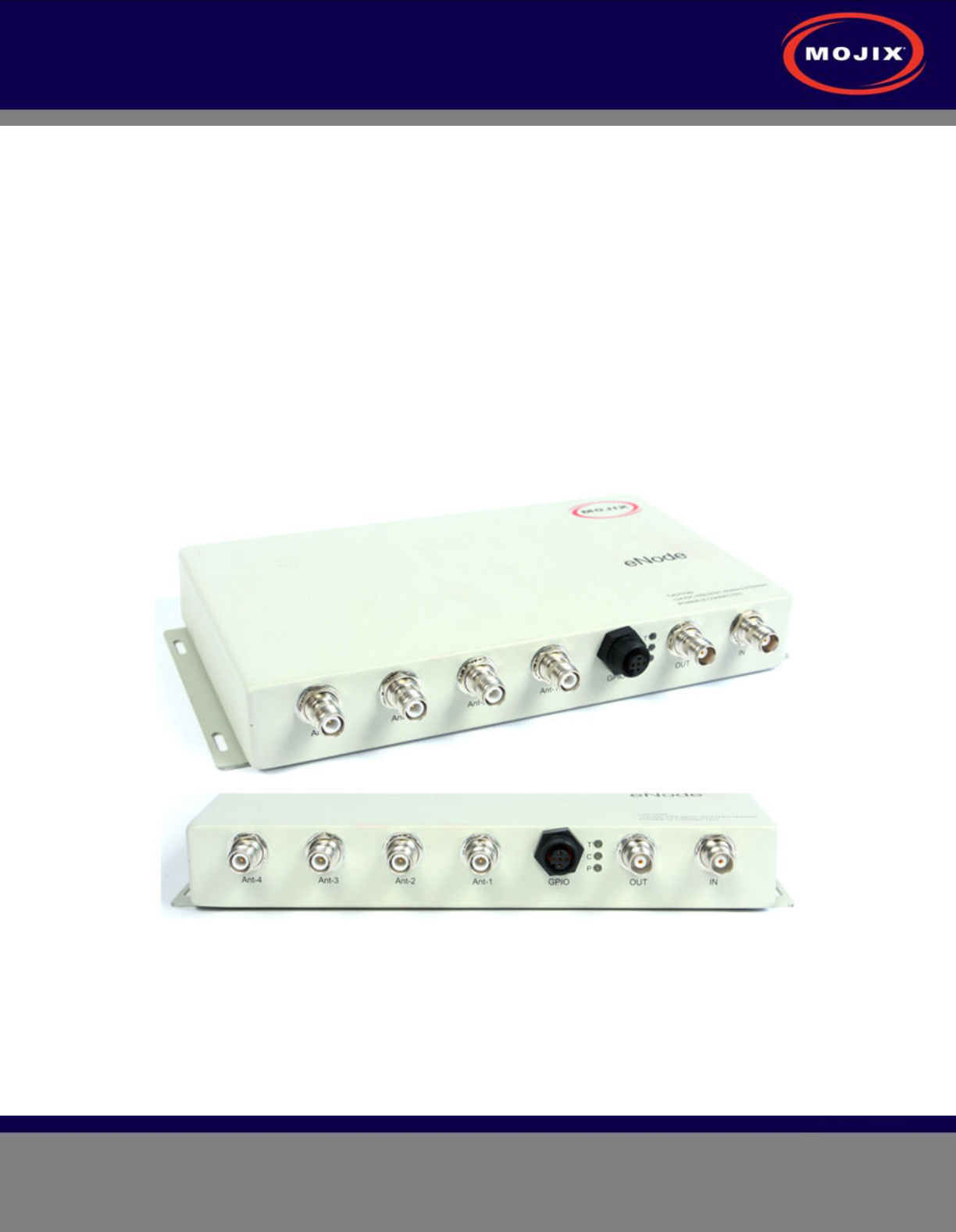
Figure 9 shows the eNode and its interfaces, and Table 1 details the specifications of its interface
connectors.
Figure 9: eNode Interfaces

STAR 3000 Installation Manual
Mojix Incorporated
www.mojix.com
(877) 886-6549
Page
16
of
36
Confidential and Proprietary
eNode Connector Function Connector Type
RF Input connector TNC connector
RF Output connector TNC connector
Antenna – 1 output connector TNC-RP connector
Antenna – 2 output connector TNC-RP connector
Antenna – 3 output connector TNC-RP connector
Antenna – 4 output connector TNC-RP connector
GPIO connector 5-conductor circular
Table 1: eNode Connector Specification
Part Numbers:
(Indoor / Outdoor)
FCC/Americas: ENM-3004-F
EU: ENM-3004-E
Japan: ENM-3004-J
Korea: ENM-3004-K
Brazil: ENM-3004-B
Singapore: ENM-3004-S
Frequency: FCC/Americas: 902 – 928 MHz
EU: 865 – 868 MHz
Japan: 916.7 – 920.9 MHz
Korea: 917 – 923.5 MHz
Brazil: 902 – 907.5, 915 – 928 MHz
Singapore: 920 – 925 MHz
Power: 24 VDC from RF input
Dimensions (L x W x H): 10.5” x 6.25” x 1.5” (26.7cm x 15.9cm x 3.8cm)
Weight: 2.5 lbs (1.1 kg)
Operating Temperature: -30°C to +60°C
Storage Temperature: -40°C to +85°C
Humidity: 5 – 95% non-condensing
Environmental Rating: IP65
Regulatory: FCC Part 15, EN 60950, EN 50364, EN 301 489-1
EN 301 489-3, EN 302 208-2
Maximum Transmit Power: Compliant with local regulations
Physical Interfaces: Antenna transmit connectors: 4 TNC-RP Male
Input: TNC female
Output: TNC female
General Purpose I/O connector: Circular Connector
Indicators: Power, Command Link, Transmit
Mounting Configuration: Built-in mounting ears
Tag Waveform and Protocols: EPC Class 1 Gen 2 Compliant
ISO 18000-6 Compliant
Insertion Loss for Daisy Chaining: 0.8 dB
Table 2: eNode Operating Specification
STAR 3000 Installation Manual
Mojix Incorporated
www.mojix.com
(877) 886-6549
Page
17
of
36
Confidential and Proprietary
EMUX INSTALLATION
eNodes frequently are deployed with eMuxes that can connect multiple eNodes to a STAR or to another
(upstream) eMux. The eMux amplifies and conditions RF signals from the STAR and provides DC power
to eNodes. This section describes the steps involved to install an eMux. eMuxes should be used either
when:
1. The insertion loss from long lengths of coaxial cables and eNodes is too high
2. The wired eNode system layout requires splitting the wiring to multiple wiring branches
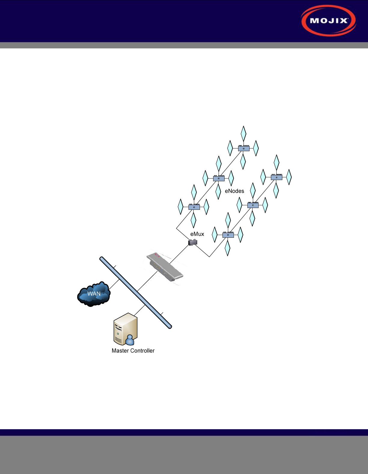
Figure 10: Example Cabling Diagram for eNodes and eMuxes
About Insertion Loss
The STAR transmits a signal of +23 dBm. Insertion loss of coaxial cable varies from one cable to the
next. For reference purposes, LMR-240 or equivalent cable has a loss of approximately 7.5 dBm per 100
feet (24.8 dB per 100 m) when measured at 865 MHz to 928 MHz. Insertion loss of wired eNodes is 0.8
dBm. Input power levels for both the eMux and the eNode must be greater than -10 dBm. In order to
increase the signal strength for longer cable runs or many eNodes connected together, an eMux must be
STAR 3000 Installation Manual
Mojix Incorporated
www.mojix.com
(877) 886-6549
Page
18
of
36
Confidential and Proprietary
used to amplify the signal. The maximum output level on an eMux for any of the 4 output ports is +22
dBm and the maximum gain of the eMux is 30 dB.
eMux Specifications
The eMux is used to expand a single input into four outputs to create a distributed architecture, as well as
to provide power to extend the operational range of the STAR wired eNode network. The eMux powers
the RFID and Command signals present on its input port to compensate for the cable loss and provides
the amplified signal on its 4 output ports. Each eMux output port can drive up to 10 cascaded eNodes
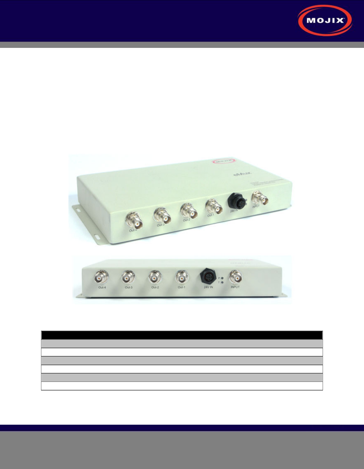
powering up to 40 eNodes. Figure 11 depicts the eMux and its interfaces, showing the RF connections as
well as the power supply connection. The connector specification is summarized in Table 3 below.
Figure 11: eMux Interfaces
eMux Connector Function Connector Type
RF input connector TNC connector
RF output connector – 1 TNC connector
RF output connector – 2 TNC connector
RF output connector – 3 TNC connector
RF output connector – 4 TNC connector
Power Supply Connector External Power Supply
Table 3: eMux Connector Specification

STAR 3000 Installation Manual
Mojix Incorporated
www.mojix.com
(877) 886-6549
Page
19
of
36
Confidential and Proprietary
Part Numbers: Indoor:
EMX-3004-W
EMX-3004-EW
Outdoor:
EMX-3004-WO
EMX-3004-EWO
Frequency: 865 – 928 MHz
Maximum Power Consumption: 10 Watts
Maximum DC Power Supply: 130 Watts
Power: 24 VDC input
Power Supply: 115 VAC input; 24 VDC, 5.41 A output (EMX-3004-W Model)
230 VAC input; 24 VDC, 5.41 A output (EMX-3004-EW Model)
Dimensions (L x W x H): 10.5” x 6.25” x 1.5” (26.7cm x 15.9cm x 3.8cm)
Weight: 2.5 lbs (1.1 kg)
Operating Temperature: -30°C to +60°C
Storage Temperature: -40°C to +85°C
Humidity: 5 – 95% non-condensing
Regulatory: FCC Part 15, EN 60950, EN 50364, EN 301 489-1
EN 301 489-3, EN 302 208-2
Maximum RF Output Power: 22 dBm
Maximum Gain: 30 dB
Physical Interfaces: Input: 1 TNC female
Output: 4 TNC female
DC Input: 5-Pin Circular
Indicators: Power, Status
Mounting Configuration: Built-in mounting ears
Table 4: eMux Operating Specification
STAR 3000 Installation Manual
Mojix Incorporated
www.mojix.com
(877) 886-6549
Page
20
of
36
Confidential and Proprietary
EXPANDER INSTALLATION
The eXpander module provides a cost effective means of increasing antenna densities by expanding the
total number of antennas from 4 to 16 per eNode as depicted in the drawing below. The eXpander offers
a smaller form factor to help simplify deployments and further reduce installation costs. The interfaces
and operating specification are detailed in Figure 12 and Table 3 below.
Figure 12: eXpander Interfaces
Part Number: EXP-3004-W
Maximum Power Consumption: 0.75 Watts
Insertion Loss: 1.8 dB
Input Connector: TNC Female
Output Connectors: TNC-RP Female
Termination: Required only on used ports
Dimensions (L x W x H): 4.8” x 3.2” x 2.2” (12.1cm x 8.1cm x 5.6cm)
Weight: 0.5 lbs (0.23 kg)
Mounting Configuration: Includes 2 brackets
Frequency: 850 to 950 MHz
Operating Temperature: -30°C to +60°C
Storage Temperature: -40°C to +85°C
Regulatory: FCC Part 15 (in process), IEC 60950 (in
process)
Environmental: IP65 rated
Table 5: eXpander Operating Specification
STAR 3000 Installation Manual
Mojix Incorporated
www.mojix.com
(877) 886-6549
Page
21
of
36
Confidential and Proprietary
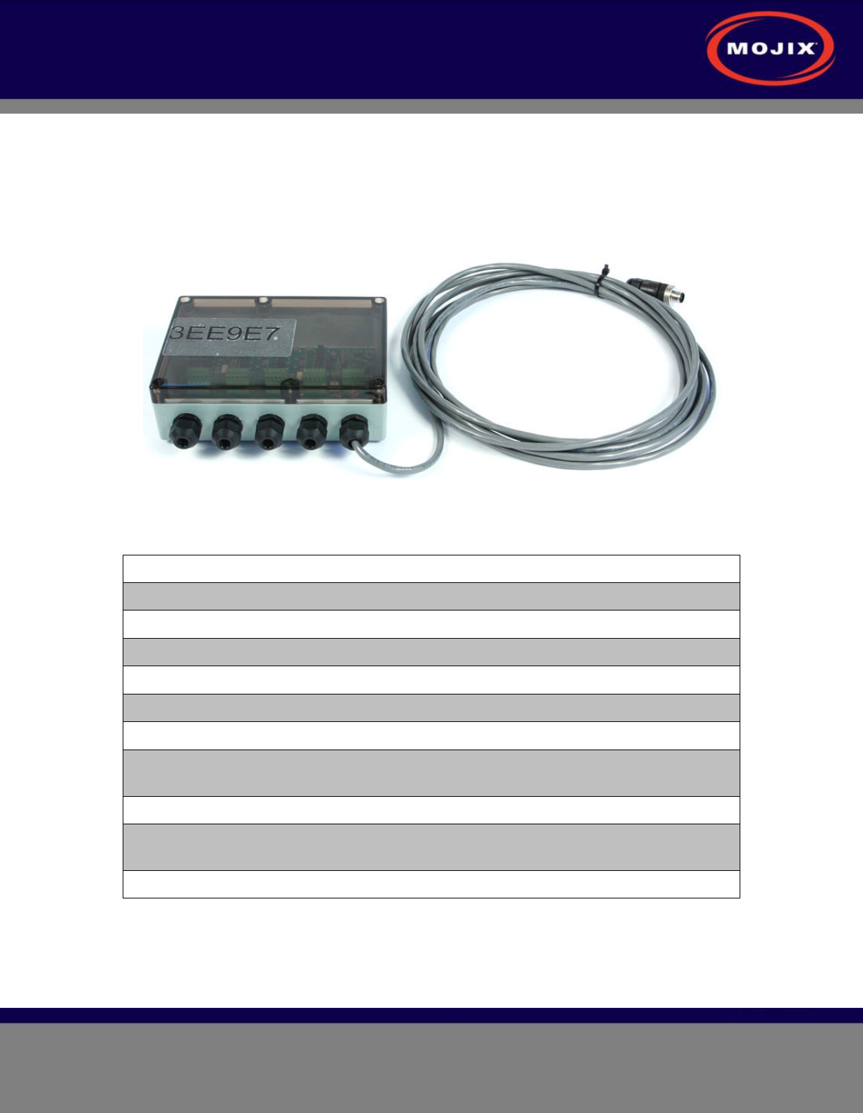
GPIO INSTALLATION
The GPIO or General Purpose Input/Output is an interface card that connects different types of sensors
and actuator devices such as infrared presence sensors and light stacks to an eNode. The GPIO unit is
powered by an interfacing cable from the eNode. The GPIO unit, as shown in Figure 13 below, has a
unique ID which is added to the configuration of the Mojix MCON software. Each sensor connected to the
GPIO unit has a position ID within the GPIO and this ID is mapped to the eNode in the MCON software.
Figure 13: GPIO Unit with RS-485 Cable
The operating specification for the GPIO unit is as follows.
Part Number: GPO-3008-W
Input Power: 24 VDC and 5 VDC from eNode
Dimensions (L x W x H): 7.08” x 4.92” x 2.2” (18.0cm x 12.5cm x 5.6cm)
Weight: 0.5 lbs (0.2 kg)
Operating Temperature: -40°C to +85°C
Humidity: 5 – 95% non-condensing`
Environmental Rating: IP65
Regulatory Compliance: FCC Part 15, EN 60950, EN 50364, EN 301
489-1, EN 301, 489-3, EN 302 208-2
Physical Interfaces: Terminal lugs
Mounting Configuration: Built-in mounting ears, mounting hardware
included
External Component Interfaces: 1 eNode, 8 sensors, 8 actuators
Table 6: GPIO Operating Specification
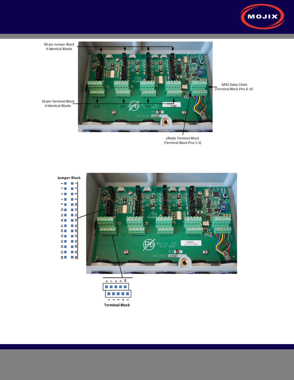
Product Overview
The Terminal block is used to connect wires to and from the external sensor/actuator devices. The
Jumper block allows the circuits to be configured.
STAR 3000 Installation Manual
Mojix Incorporated
www.mojix.com
(877) 886-6549
Page
22
of
36
Confidential and Proprietary
Figure 14: GPIO Unit Terminal Blocks
Each configuration group, made up of one terminal block and one jumper block, allow the configuration of
the two sensor circuits and two actuator circuits as required.
Figure 15: GPIO Unit Jumper Blocks
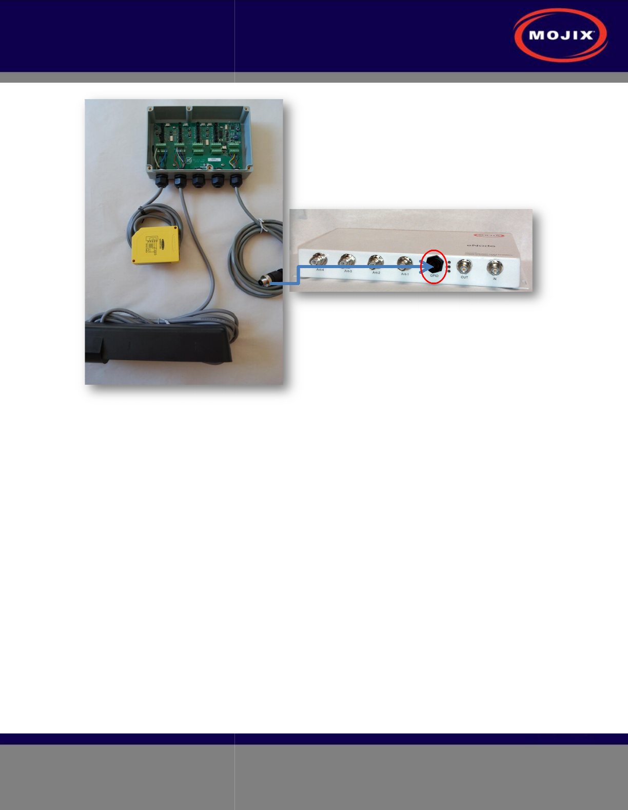
The eNode uses an RS-485 type connection to both power and command the GPIO unit. The following
figure illustrates how this connection is made.
STAR 3000 Installation Manual
Mojix Incorporated
www.mojix.com
(877) 886-6549
Figure
Installers will need the following set of tools to perform a proper GPIO installation.
• Medium-
size Phillips screw driver for the cover of the GPIO
• Small-
size Phillips screw driver for the GPIO terminal block connectors
•
Wire cutter to shorten connectors and/or connector cables (if necessary)
GPIO Cabling
The GPIO unit comes with the input ca
be daisy-chained together. Figure
17
block.
Figure
16: GPIO / eNode Physical Interface
Installers will need the following set of tools to perform a proper GPIO installation.
size Phillips screw driver for the cover of the GPIO
size Phillips screw driver for the GPIO terminal block connectors
Wire cutter to shorten connectors and/or connector cables (if necessary)
The GPIO unit comes with the input ca
ble pre-
installed, however, in the case where GPIO boxes ne
17
and Table 7 provide wiring and pin-
out details for the input terminal
Page
23
of
36
Confidential and Proprietary
installed, however, in the case where GPIO boxes ne
ed to
out details for the input terminal
STAR 3000 Installation Manual
Mojix Incorporated
www.mojix.com
(877) 886-6549
Page
24
of
36
Confidential and Proprietary
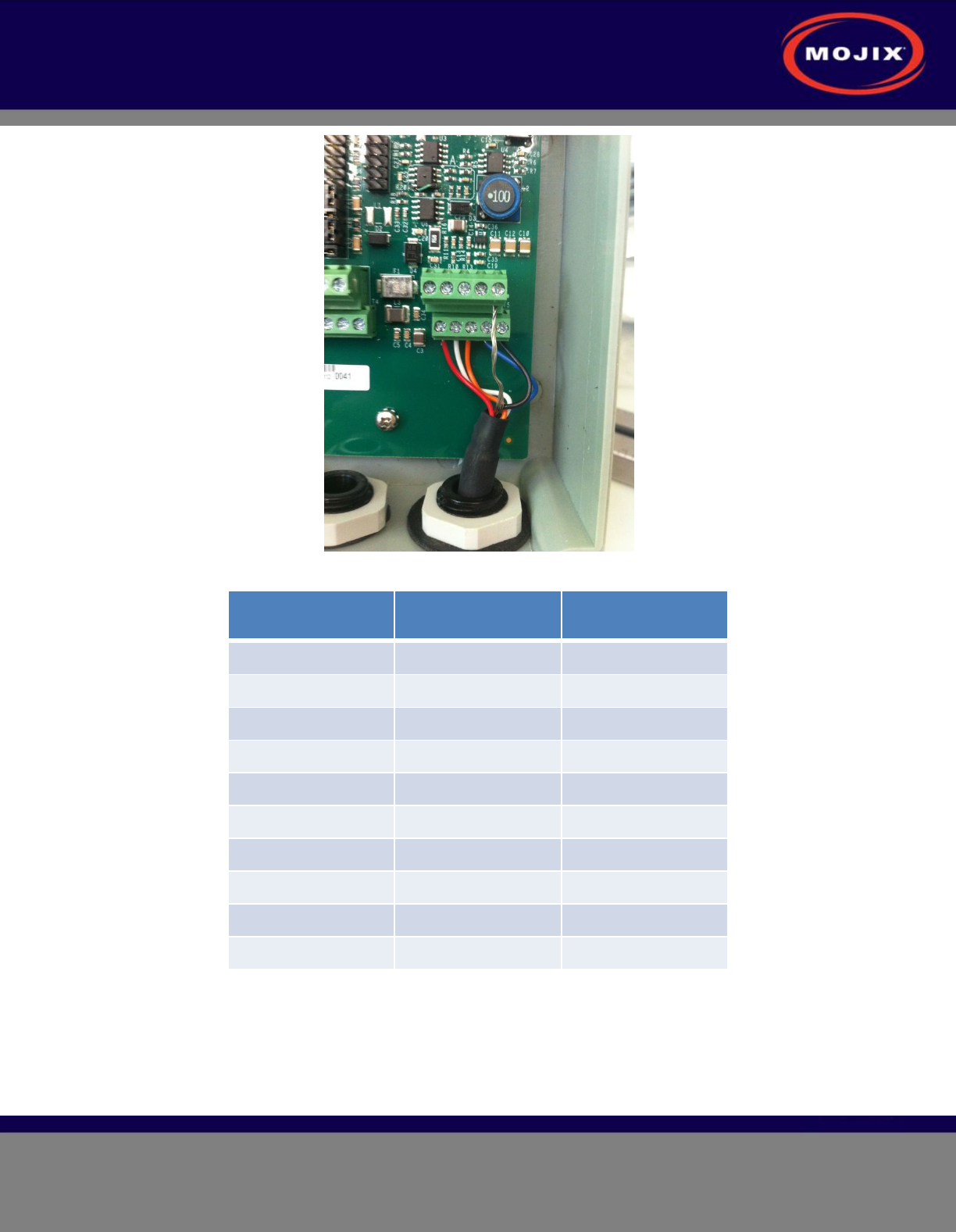
Figure 17: GPIO Input Terminal Wiring
Terminal Block Pin Wire Color Signal
1 Red 24V
2 White RS-485 A
3 Orange RS-485 B
4 Blue + 3V
5 Black GND
6 - -
7 - -
8 - -
9 - -
10 Shield GND
Table 7: GPIO Input Terminal Block
For directions on how to connect sensors and actuators to the GPIO unit, please refer to the GPIO user
guide provided separately.