MOJIX CBLENODE3K Star 3000 System User Manual USERMANUAL STAR3000 2 0 1x
MOJIX, Inc. Star 3000 System USERMANUAL STAR3000 2 0 1x
MOJIX >
Contents
- 1. Users Manual Part 1
- 2. Users Manual Part 2
- 3. Users Manual Part 3
- 4. Users Manual Part 4
- 5. Users Manual Part 5
Users Manual Part 3
STAR 3000 Installation Manual
Mojix Incorporated
www.mojix.com
(877) 886-6549
Page
9
of
36
Confidential and Proprietary
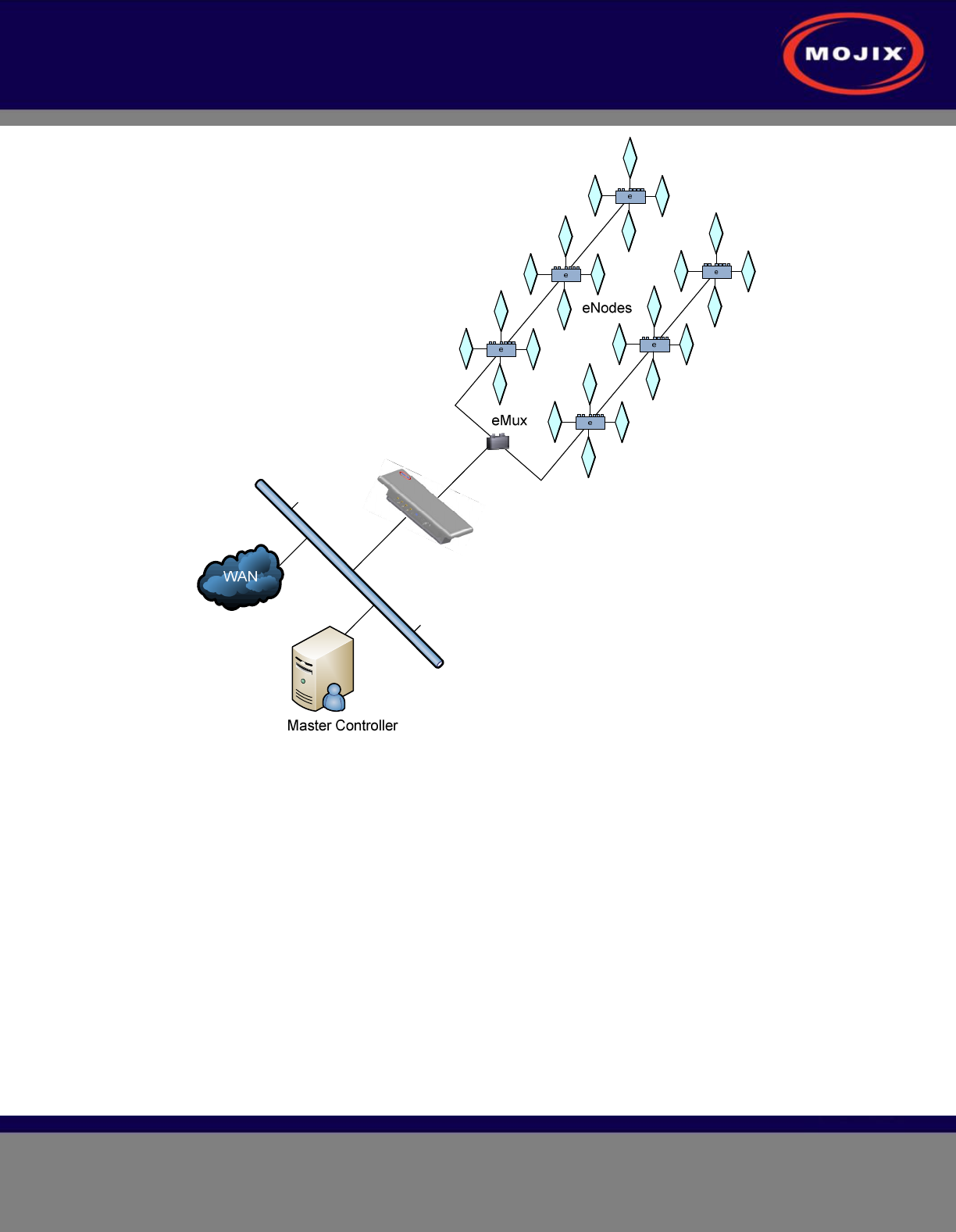
Figure 2: STAR System Topology
SYSTEM COMPONENTS
1. STAR
2. eMux: splitter and amplifier for the RF signal
3. eNode: controls up to 4 antennas to excite tags
4. Master Controller (MCON): application appliance
5. Optional Sensor network to detect activity in specific areas
STAR 3000 Installation Manual
Mojix Incorporated
www.mojix.com
(877) 886-6549
Page
10
of
36
Confidential and Proprietary
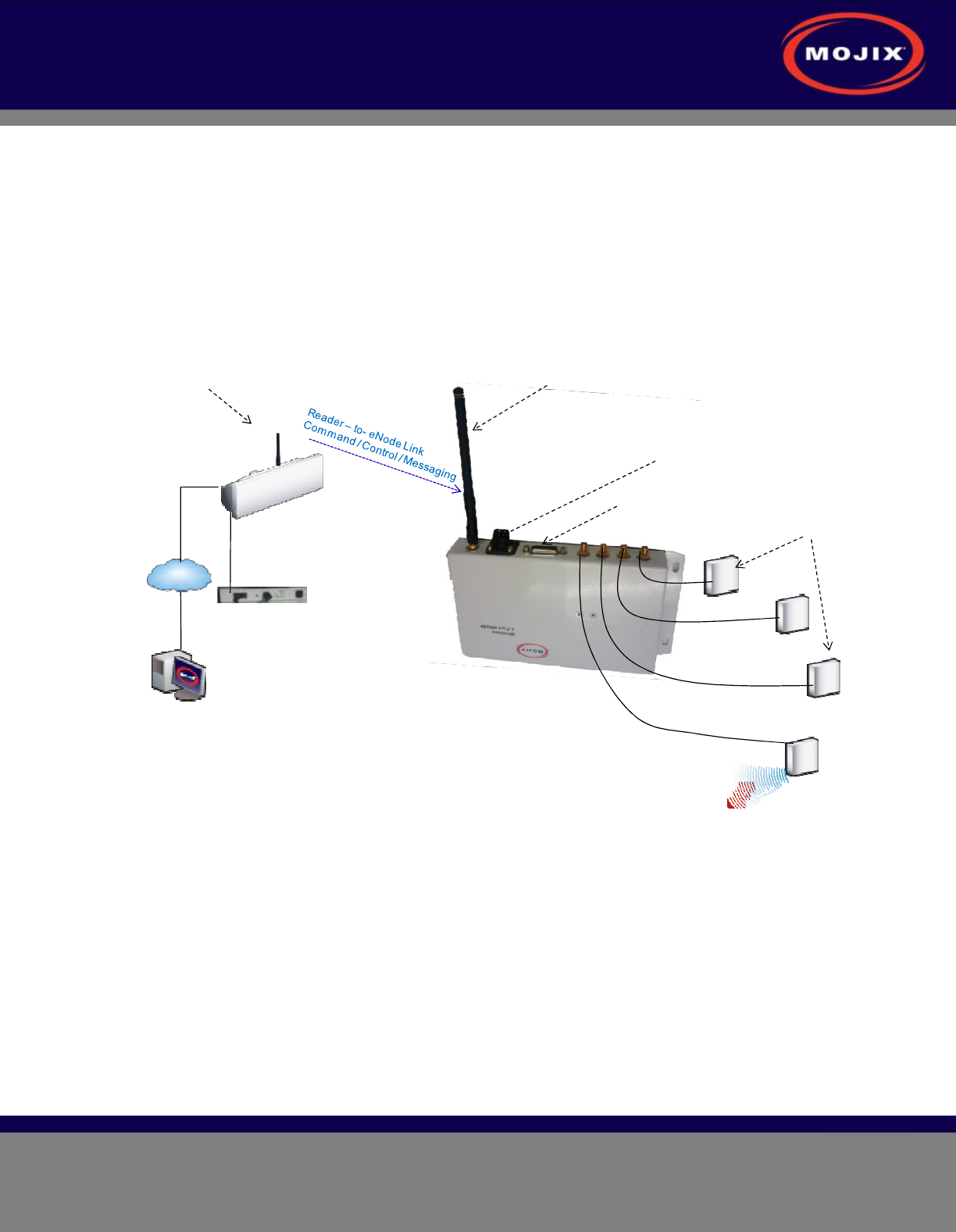
Wireless STAR System Topology
Figure 3 illustrates Wireless STAR system topology, showing:
1. STAR and power supply, including the command link antenna
2. Wireless 4-port eNode, including the command link antenna
3. Sensor port
4. eNode transmit antennas
5. MCON
Figure 3: Wireless STAR System Topology
LAN line
Master Controller
Wireless
TAR Reader
LAN
Power Supply
Transmit Antenna
Wireless
4 Port eNode Coaxial Cable
Sensors
External Power Supply
Command Link
Receive Only Antenna
Command Link
Transmit Only Antenna
Tag
STAR 3000 Installation Manual
Mojix Incorporated
www.mojix.com
(877) 886-6549
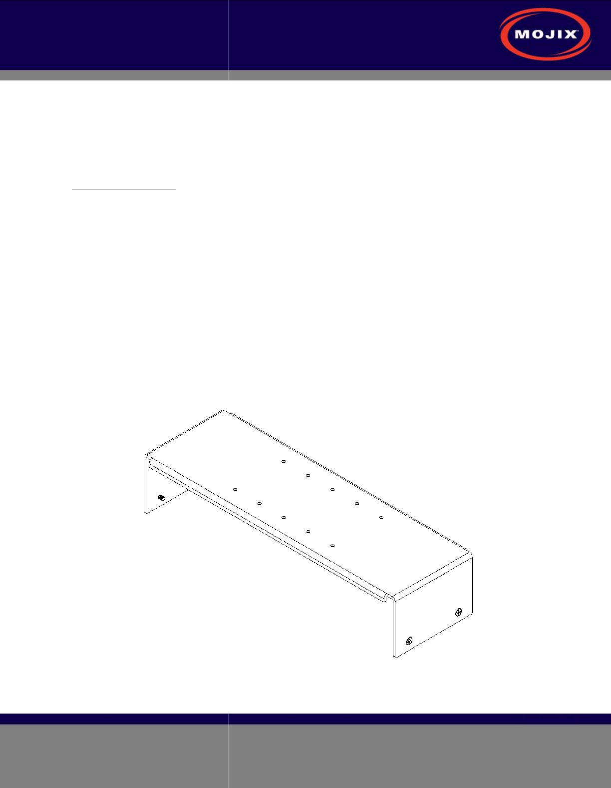
STAR RECEIVER
INSTALLATION
STAR Receiver Installation
The STAR
is mechanically designed for post
bracket. This bracket is designed to be used with any standard VESA mounting bracket.
figure, the mounting
bracket is installed directly on the STAR
Installation instructions:
1. Product installation
shall be conducted by a qualified installer.
architect shall be consulted to ensure the wall and/or pole mount is capable of safely
4 times the weight of the product.
2.
Should the customer elect to mount the STAR
main mounting
bracket to accommodate a family of hardware
3. When mounting STAR
unit to a flat surface, a minimum of 4 fasteners are
type is a function of the wall material and construction.
a. For example
: toggle bolts or Molly bolts would be the first choice on hollow walls.
shields would be recommended on solid (cast) concrete or brick.
recommended, but could be used only if the wood material of the wall was at
4. The STAR Receiver is first
secured to the main bracket using the
VESA bracket designed to hold 4 times the weight of the STAR unit should separately be mounted to
either a mast
or a flat surface. The last step is to attach the STAR bracket to the VESA bracket.
Figure 4:
INSTALLATION
is mechanically designed for post
or wall mounting. Figure 4 illustrates the
rear mounting
bracket. This bracket is designed to be used with any standard VESA mounting bracket.
bracket is installed directly on the STAR
Receiver back plate.
shall be conducted by a qualified installer.
The appropriate local engineer or
architect shall be consulted to ensure the wall and/or pole mount is capable of safely
4 times the weight of the product.
Should the customer elect to mount the STAR
to a flat surface (e.g. wall), holes are provided in the
bracket to accommodate a family of hardware
(customer supplied).
unit to a flat surface, a minimum of 4 fasteners are
required
, though the exact
type is a function of the wall material and construction.
Best industry practice is recommended.
: toggle bolts or Molly bolts would be the first choice on hollow walls.
shields would be recommended on solid (cast) concrete or brick.
Nails are not
recommended, but could be used only if the wood material of the wall was at
secured to the main bracket using the
provided hardware.
VESA bracket designed to hold 4 times the weight of the STAR unit should separately be mounted to
or a flat surface. The last step is to attach the STAR bracket to the VESA bracket.
STAR 3000 VESA Interface Mount Bracket
Page
11
of
36
Confidential and Proprietary
rear mounting
bracket. This bracket is designed to be used with any standard VESA mounting bracket.
As shown in the
The appropriate local engineer or
architect shall be consulted to ensure the wall and/or pole mount is capable of safely
supporting up to
to a flat surface (e.g. wall), holes are provided in the
, though the exact
Best industry practice is recommended.
: toggle bolts or Molly bolts would be the first choice on hollow walls.
Lead lag
Nails are not
recommended, but could be used only if the wood material of the wall was at
least 1.5" thick.
provided hardware.
A standard
VESA bracket designed to hold 4 times the weight of the STAR unit should separately be mounted to
or a flat surface. The last step is to attach the STAR bracket to the VESA bracket.
STAR 3000 Installation Manual
Mojix Incorporated
www.mojix.com
(877) 886-6549
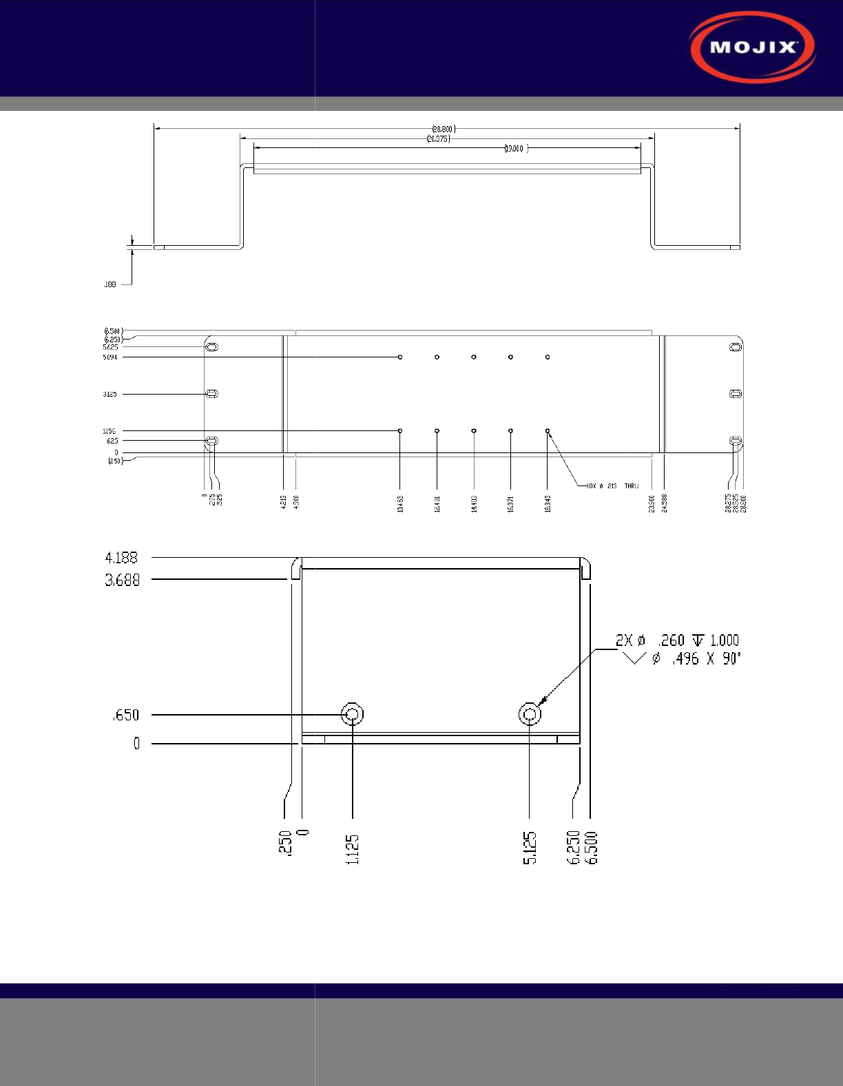
Figure 5
: VESA
Figure 6
: VESA
Figure 7
: VESA
: VESA
Interface Mount Bracket Side View
: VESA
Interface Mount Bracket Rear View
: VESA
Interface Mount Bracket End Profile View
Page
12
of
36
Confidential and Proprietary