MTRLC MG7540 16x4 DOCSIS 3.0 Cable Modem plus AC1600 Router User Manual
MTRLC LLC 16x4 DOCSIS 3.0 Cable Modem plus AC1600 Router
MTRLC >
Contents
- 1. User Manual.PDF
- 2. User Manual
User Manual.PDF

MG7540
16x4 DOCSIS 3.0 Cable
Modem plus AC1600 Router
User Manual
VER: 1.0

MG7540 Cable Modem User Manual
i
Contents
1Safety Precautions ............................................................................................. 1
2Overview ............................................................................................................ 2
2.1Application ............................................................................................. 2
2.2Features ................................................................................................ 2
2.3Standards Compatibility and Compliance ............................................. 3
3Hardware Description and Hardware Installation ............................................... 4
3.1Hardware Description ............................................................................ 4
3.1.1Front Panel ................................................................................. 4
3.1.2Rear Panel .................................................................................. 5
3.2Hardware Installation ............................................................................. 6
3.2.1Connecting the Device ............................................................... 6
4PC Network Configuration and Login ................................................................. 7
4.1PC Network Configuration ..................................................................... 7
4.2Logging In to the MG7540 Cable Modem ............................................. 9
5Web-Based Management ................................................................................ 11
5.1Status .................................................................................................. 11
5.1.1Software .................................................................................... 11
5.1.2Connection................................................................................ 12
5.1.3Diagnostics ............................................................................... 14
5.1.4Security ..................................................................................... 15
5.1.5Event Log .................................................................................. 16
5.2Basic Router ........................................................................................ 16
5.2.1Setup ........................................................................................ 16
5.2.2DHCP ........................................................................................ 18
5.2.3DHCPv6 .................................................................................... 20
5.2.4LAN IPv6 ................................................................................... 21
5.2.5DDNS ........................................................................................ 21
5.2.6Backup/Restore ........................................................................ 22
5.3Advanced Router ................................................................................. 23
5.3.1Options ..................................................................................... 23
5.3.2IP Filtering ................................................................................. 25
5.3.3MAC Filtering ............................................................................ 26
5.3.4Port Filtering ............................................................................. 26
5.3.5Forwarding ................................................................................ 27

MG7540 Cable Modem User Manual
ii
5.3.6Port Triggers ............................................................................. 29
5.3.7RIP Setup ................................................................................. 29
5.3.8DMZ Host .................................................................................. 32
5.4Wireless ............................................................................................... 33
5.4.1Basic ......................................................................................... 33
5.4.2Radio ........................................................................................ 35
5.4.3WPS_RADIUS_WEP ................................................................ 35
5.4.4Guest ........................................................................................ 38
5.4.5Access ...................................................................................... 39
5.4.6Advanced .................................................................................. 41
5.4.7WMM ........................................................................................ 45
5.4.8Scan/Bridging ........................................................................... 47
5.5Protection & Parental Control .............................................................. 47
5.5.1Firewall Basic ............................................................................ 48
5.5.2Event Log .................................................................................. 49
5.5.3Parental Control ........................................................................ 50
5.6VPN ..................................................................................................... 51
5.6.1IPSec ........................................................................................ 51
5.6.2L2TP/PPTP ............................................................................... 52
5.6.3Event Log .................................................................................. 53
5.7Logout .................................................................................................. 54
6Q&A .................................................................................................................. 55

MG7540 Cable Modem User Manual
1
1 Safety Precautions
Read the following information carefully before operating the device. Please follow
the following precaution items to protect the device from risks and damage caused
by fire and electric power:
Use volume labels to mark the type of power.
Use the power adapter that is packed within the device package.
Pay attention to the power load of the outlet or prolonged lines. An
overburden power outlet or damaged lines and plugs may cause electric
shock or fire accident. Check the power cords regularly. If you find any
damage, replace it at once.
Proper space left for heat dissipation is necessary to avoid any damage
caused by overheating to the device. The holes on the device are designed
for heat dissipation to ensure that the device works normally. Do not cover
these heat dissipation holes.
Do not put this device close to a place where a heat source exits or high
temperature occurs. Avoid the device from direct sunshine.
Do not put this device close to a place where is over damp or watery. Do not
spill any fluid on this device.
Do not connect this device to any PC or electronic product, unless our
customer engineer or your broadband provider instructs you to do this,
because any wrong connection may cause any power or fire risk.
Do not place this device on an unstable surface or support.
The screen of the coaxial cable is intended to be connected to earth in the
building installation.

MG7540 Cable Modem User Manual
2
2 Overview
The MG7540 is targeted towards DOCSIS3.0 cable modem and gateway. With
sixteen downstream channels and four upstream channels, it supports up to
600Mbs/160Mbs.The MG7540 incorporates a variety of industry standard
peripheral interfaces including dual IEEE802.3 10/100/1000Mbps interface, one
with integrated GPHY. The MG7540 supports WLAN access. It complies with IEEE
802.11,802.11b/g,802.11n and 802.11ac specifications, WEP, WPA, and WPA2
security specifications. The 2.4GHz WLAN of the MG7540 supports 2T2R, The
5GHz WLAN of the MG7540 supports 3T3R.
2.1 Application
Home gateway
SOHOs
Small enterprises
Higher data rate broadband sharing
Audio and video streaming and transfer
PC file and application sharing
Network and online gaming
2.2 Features
User-friendly GUI for web configuration
Several pre-configured popular games. Just enable the game and the port
settings are automatically configured.
Compatible with all standard Internet applications
WLAN with high-speed data transfer rates of up to 600 Mbps, compatible
with IEEE 802.11b/g/n/ac, 2.4GHz/5GHz compliant equipment
IP routing and bridging
Network/port address translation (NAT/PAT)
Wireless LAN security: WPA, 802.1x, RADIUS client

MG7540 Cable Modem User Manual
3
Universal plug-and-play(UPnP)
File server for network attached storage (NAS) devices
Web filtering
Remote update
System statistics and monitoring
2.3 Standards Compatibility and Compliance
Support application level gateway (ALG)
DOCSIS3.0
IEEE 802.3
IEEE 802.3u
IEEE 802.11b
IEEE 802.11g
IEEE 802.11n
IEEE 802.11ac

MG7540 Cable Modem User Manual
4
3 Hardware Description and Hardware Installation
3.1 Hardware Description
3.1.1 Front Panel
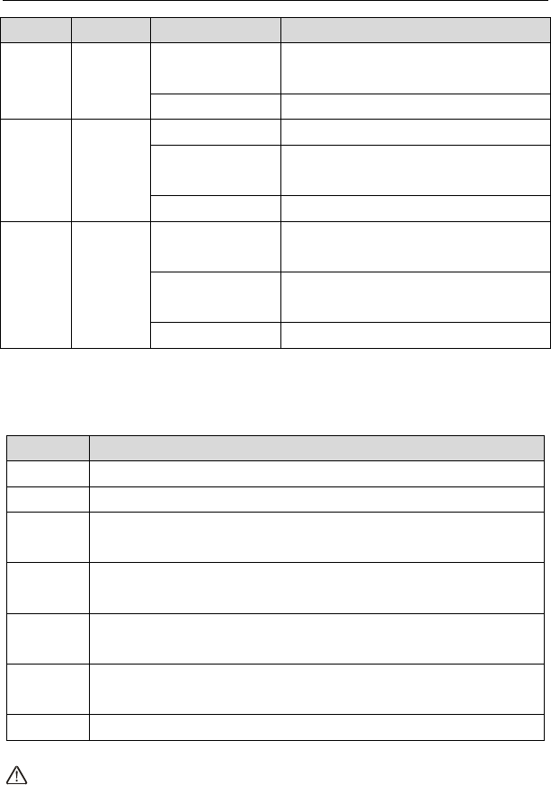
The following table describes the indicators on the front panel.
Indicator Color Status Description
Power Green On The device is powered on and the device
operates normally.
Off The device is powered off.
D/S
Green
On CM has locked D/S frequency
Blink CM scan D/S frequency
Off Device is powered off.
Blue
On CM has locked D/S channel bonding
Blink CM is on D/S channel bonding
Off Device is powered off.
U/S
Green
On CM has locked U/S frequency
Blink CM is range and scan U/S frequency
Off Device is powered off or CM scan D/S
frequency.
Blue
On CM has locked U/S channel bonding
Blink CM is on U/S channel bonding
Off Device is powered off or CM scan D/S
frequency.
Internet Green
On CM online.
Blink Catching the wan ip address.
Off Not connect.
Ethernet Green On The Ethernet interface is connected.
MG7540 Cable Modem User Manual
5
Indicator Color Status Description
1/2/3/4 Blink Data is being transmitted through the
Ethernet interface.
Off The Ethernet interface is disconnected.
WLAN Green
On WLAN is enabled.
Blink Data is being transmitted through the
wireless interface.
Off WLAN is disabled.
WPS Green
On Connection succeeds under Wi-Fi
Protected Setup.
Blink Negotiation is in progress under Wi-Fi
Protected Setup.
Off Wi-Fi Protected Setup is disabled.
3.1.2 Rear Panel
The following table describes the interfaces or the buttons on the rear panel.
Interface Description
Antenna The antenna interface, for connecting the antennas.
Cable RF cable port, for connecting HFC cable.
Reset Press the button for at least 5 second and then release it. System
restores the factory default settings.
WPS Press the button for at least 5 second and then release it. WPS will
disabled/enabled.
WLAN Press the button for at least 3 second and then release it. Wireless
will disabled/enabled.
Eth 4~1 RJ-45 port, for connecting the router to a PC or another network
device.
Power Power interface, for connecting the power adapter.
Warning:

MG7540 Cable Modem User Manual
6
Do not press the Reset button unless you want to clear the current settings. The
Reset button is in a small circular hole on the rear panel. If you want to restore the
default settings, please press the Reset button gently for 5 second with a fine needle
inserted into the hole and then release the button. The system reboots and returns to
the factory defaults.
3.2 Hardware Installation
3.2.1 Connecting the Device
Please follow the steps below to connect the device.
Step1 Connect the Cable port of the CM/RG with HFC cable.
Step2 Connect the Eth port of the CM/RG to the network card of the PC via an
Ethernet cable.
Step3 Plug one end of the power adapter to the wall outlet and connect the
other end to the Power port of the CM/RG.

MG7540 Cable Modem User Manual
7
4 PC Network Configuration and Login
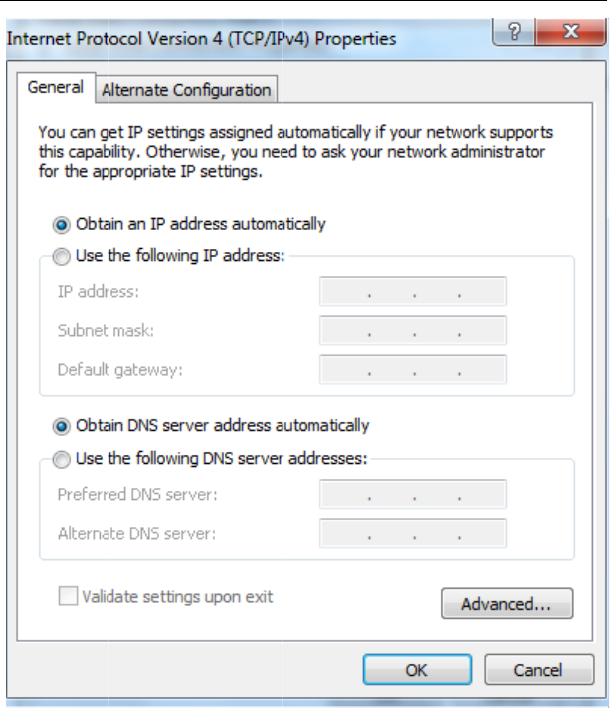
4.1 PC Network Configuration
Each network interface on the PC should either be configured with a statically defined
IP address and DNS address, or be instructed to automatically obtain an IP address
using the network DHCP server. MG7540 provides a DHCP server on its LAN and it
is recommended to configure your LAN to automatically obtain its IP address and
DNS server IP address.
The configuration principle is identical but should be carried out differently on each
operating system.
The following displays the TCP/IP Properties dialog box on Windows 7.
TCP/IP config
u
Step1 Ch
Step2 Ri
g
Step3 On
a
n
MG7540 Cable
Figure 1 IP and DN
S
u
ration steps for Window
s
oose Start > Control P
a
g
ht-click the Ethernet co
n
the General tab, selec
t
n
d click Properties.
Modem User Manual
8
S
configuration
s
7 are as follows:
a
nel > Network Connec
t
n
nection icon and choose
t
the Internet Protocol
t
ions.
Properties.
(TCP/IP) component
Step4 Th
e
Step5 Se
Step6 Se
Step7 Cli
c
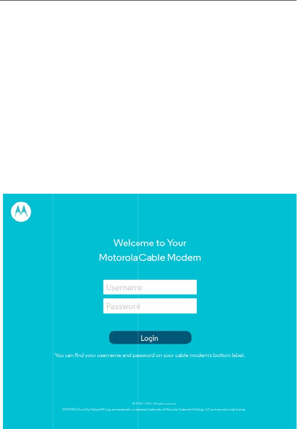
4.2 Log
g
To log in to the
Step1 O
p
Step2 En
t
m
o
Step3 En
t
an
d
Step4 Cli
c
MG7540 Cable
e
Internet Protocol (TC
P
lect the Obtain an IP ad
d
lect the Obtain DNS ser
v
c
k OK to save the settin
g
g
ing In to the MG
7
MG7540 cable modem,
p
en a Web browser on yo
t
e
r
http://192.168.0.1 (t
o
dem) in the address bar.
t
er the user name and t
h
d
the Password is motor
c
k Login to log in to the
M
Modem User Manual
9
P
/IP) Properties windo
w
d
ress automatically ra
d
v
er address automatic
a
g
s.
7
540 Cable Mod
e
do as follows:
o
ur computer.
he default IP address
o
.
The login page appears
h
e password. The defaul
t
ola.
M
G7540 cable Modem.
w
appears.
d
io button.
a
lly radio button.
e
m
o
f the MG550 cable
.
t
Username is admin
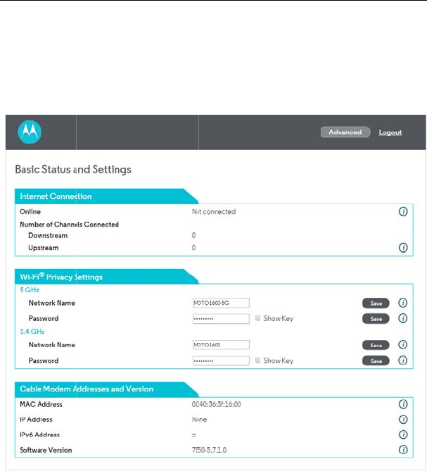
After loggin
g
click on the
A
and diagnos
e
MG7540 Cable
Figure 2 Login page
in to the MG7540 cable
A
dvanced options you ca
n
e
the system.
Modem User Manual
10
modem, it will show the
C
n
query, configure, and
m
C
M Basic Status info.
m
odify all the settings,
5 Web-
B
This chapter d
which allows
y
features and s
y
5.1 Stat
u
Choose Statu
s
5.1.1 So
f
Choose Statu
s
This page disp
l
MG7540 Cable
B
ased Manage
m
escribes how to use W
e
y
ou to configure and co
n
y
stem parameters in a u
s
u
s
s
, and the submenus of
S
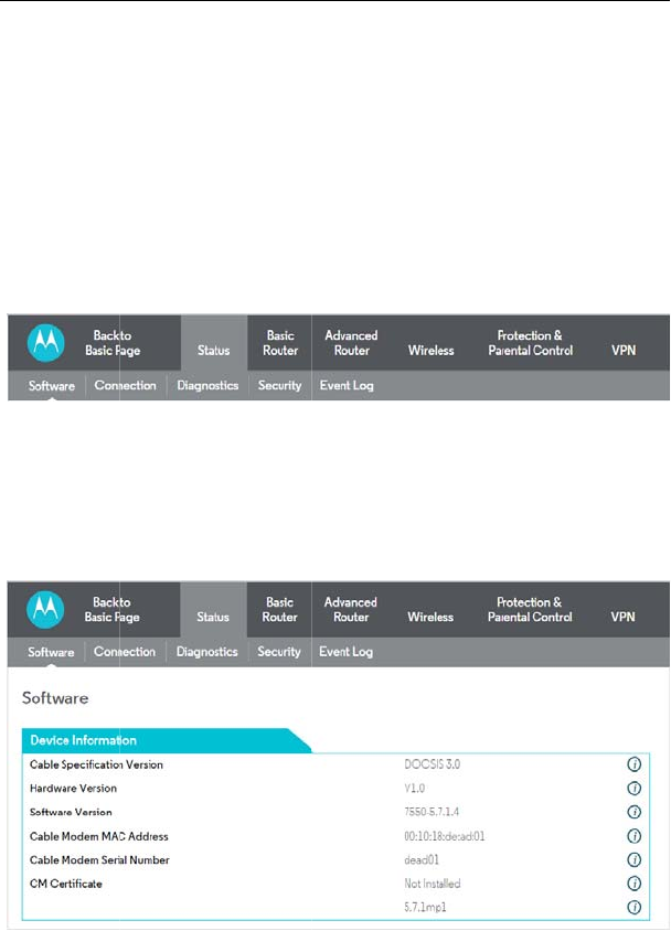
Figure 3 Submenus
f
tware
s
> Software and the foll
o
Figure 4 Software p
a
l
ays information about th
e
Modem User Manual
11
m
ent
e
b-based management
o
n
trol all of cable mode
m
s
e
r
-friendly GUI.
S
tatus are shown as bel
o
of status
o
wing page appears.
a
ge
e
hardware version, soft
w
o
f the Cable Modem,
m
residential gateway
o
w.
w
are version, MAC

MG7540 Cable Modem User Manual
12
address, cable modem IP address,serial number and CM Certificate status.
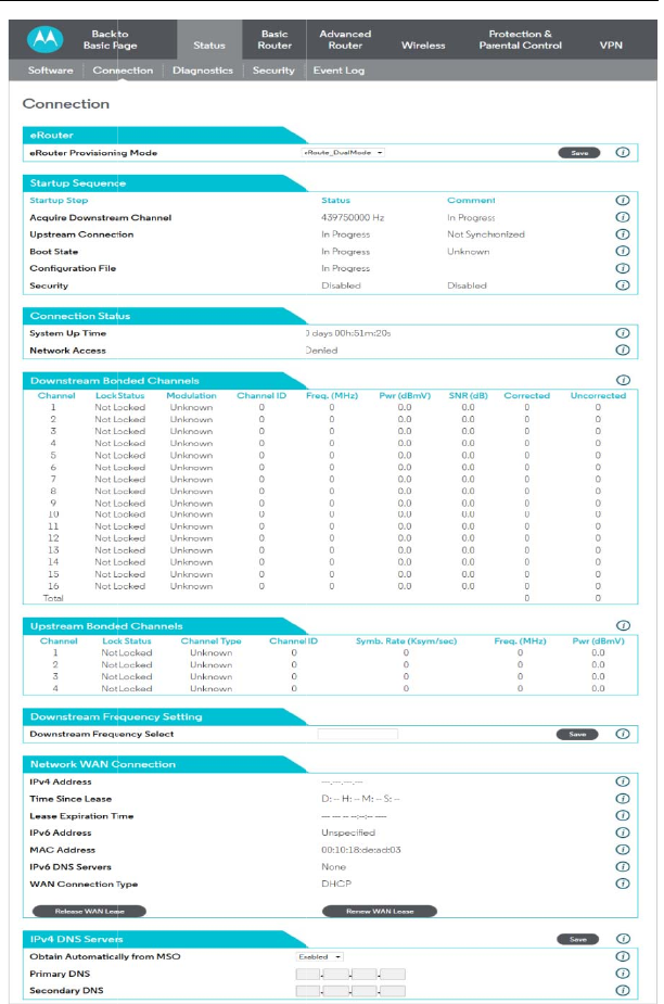
5.1.2 Connection
Choose Status > Connection and the following page appears.
MG7540 Cable Modem User Manual
13
This page dis
p
including down
downstream si
g
This page also
cable modem,
t
current system
The informatio
browser’s Refr
e
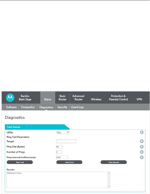
5.1.3 Di
a
Choose Statu
s
Two utilities
a
Traceroute.
Ping allows yo
u
MG7540 Cable
Figure 5 Connection
p
lays information about
t
stream channel frequen
c
g
nal power and modulati
o
displays IP lease infor
m
t
he duration of both leas
e
time from the DOCSIS t
i
n on this page can be
e
sh button.
ag
nostics
s
> Diagnostics and the
Figure 6 Diagnostic
i
a
re provided for troub
l
u
to check connectivity b
e
Modem User Manual
14
information
t
he RF upstream and d
o
c
ies, upstream channel I
D
o
n.
m
ation, including the curr
e
e
s, the expiration time of
i
meserver.
refreshed at any time
b
following page appears.
i
nformation
l
eshooting network co
n
e
tween the CM/RG and
d
o
wnstream channels,
D
s, and upstream and
e
nt IP address of the
both leases, and the
b
y clicking your web
n
nectivity: Ping and
d
evices on the LAN.
Traceroute all
o
Selecting Trac
e
the traceroute
u
and select Sta
results are dis
p
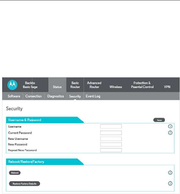
5.1.4 Se
c
Choose Statu
s
Restore Fac
t
Click this bu
t
may have c
h
Note that yo
u
new passwo
the current
p
change the
p
password.
MG7540 Cable
o
ws you to map the net
w
e
route from the drop-do
w
u
tility: To run either utility
,
rt Test to begin. The
w
p
layed in the Results tabl
e
c
urit
y
s
> Security and the foll
o
Figure 7 Security co
n
t
ory Defaults:
t
ton to restore factory de
f
h
anged.
u
can also change the s
e
rd in both the New Pass
w
p
assword in the Curren
t
p
assword. You do NOT
h
Modem User Manual
15
w
ork path from the CM/
R
w
n Utility list will present
,
make any changes to t
h
w
indow will automatically
e
.
o
wing page appears.
n
figuration
f
aults. Note that you will
l
e
curity password from th
i
w
ord and Re-Enter New
t
User ID Password fiel
d
h
ave to restore factory d
e
R
G to a public host.
alternate controls for
h
e default parameters
be refreshed as the
l
ose any settings you
i
s page by entering a
Password fields, and
d
. Clicking Save will
e
faults to change the
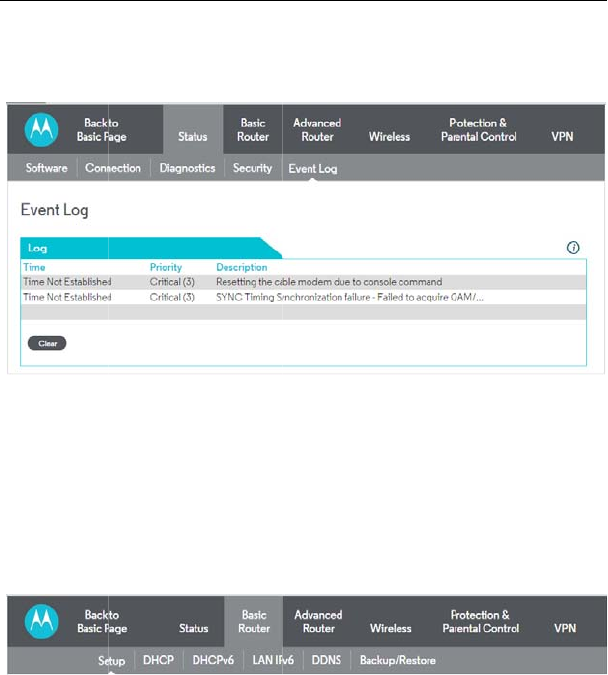
5.1.5 Ev
Choose Statu
s
The Event Lo
g
service provid
e
problems with
y
5.2 Basi
c
Choose Basic
5.2.1 Se
t
Choose Basic
MG7540 Cable
ent Lo
g
s
> Event Log and the fo
Figure 8 Event Log i
g
displays information a
b
e
r. This information m
a
y
our connection.
c
Router
Router and the submen
u
Figure 9 Submenus
t
up
Router > Setup , and th
Modem User Manual
16
llowing page appears.
nformation
b
out your cable modem'
s
a
y be particularly helpf
u
u
s of Basic Router are
s
of Basic Router
e following page appear
s
s
connection to your
u
l if you experience
s
hown as below.
s
.
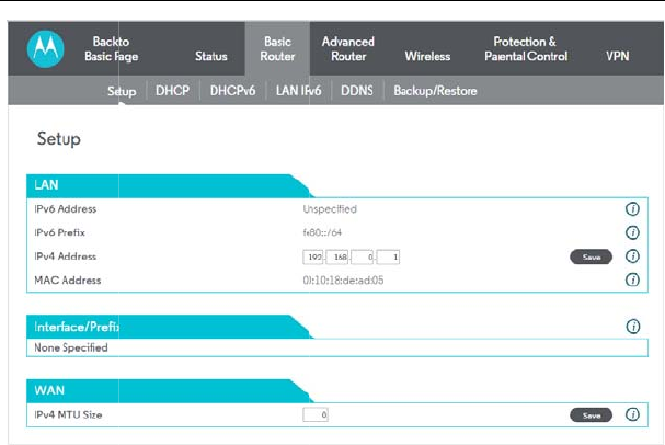
Enter the inf
o
At this point,
must do the
f
1. Power up
Internet-rout
a
2. Get an I
P
CM/RG.
Note that c
o
connection
p
access the I
n
Some confi
g
when the C
M
parameters.
the new con
f
When this m
MG7540 Cable
Figure 10 Setup con
o
rmation from the Requi
r
the CM/RG is configure
d
f
ollowing:
the CM/RG and wait f
o
a
ble IP address
P
lease from the interna
o
mmunication on the L
A
p
rovided by the cable m
o
n
ternet until the WAN co
n
g
urations settings are r
e
M
/RG first powers up. O
n
Any changes to these
s
f
iguration can be read fr
o
andatory reset is require
d
Modem User Manual
17
figuration
r
ed Information section a
s
d
for basic use. To conne
c
o
r it to register with the
C
l DHCP server for each
A
N will work regardless
o
o
dem is up. However, y
o
n
nection is enabled and
h
e
trieved only once from
n
e such setting is chang
i
s
ettings will force the C
M
o
m non-volatile storage.
d
, the web interface will
n
s
indicated:
c
t to the Internet, you
C
MTS and obtain an
PC attached to the
o
f whether the WAN
o
u will not be able to
h
as an IP address.
non-volatile storage
i
ng the IPv4 Address
M
/RG to reset so that
n
otify as follows:
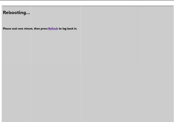
Simply wait
f
web interfac
e
Most config
u
5.2.2 D
H
Choose Basic
MG7540 Cable
Figure 11 Reload p
a
f
or the modem to reboot
e
where you made your l
a
u
ration items may be cha
n
H
CP
Router > DHCP, and th
e
Modem User Manual
18
a
ge
and click on the “Refres
h
a
st change.
n
ged on the fly without a
e
following page appears
.
h
” link to re-enter the
reboot.
.
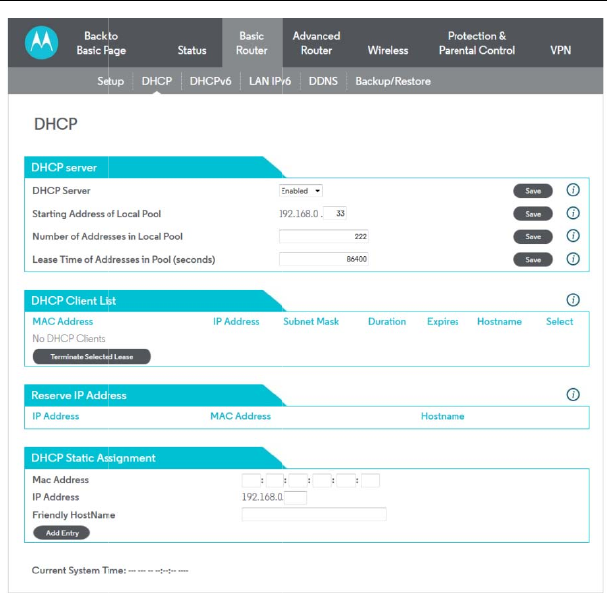
This page allo
w
LAN.
If you have yo
u
all of your PC’s
Disabled. If y
o
same subnet
255.255.255.0
)
address of the
You can also
s
change the nu
MG7540 Cable
Figure 12 DHCP co
n
w
s configuration and stat
u
u
r own DHCP server ser
v
IP addresses), you can
d
o
u do this, make sure th
e
as the external DH
C
)
, or you won’t be able
t
CM/RG can be set from
t
s
et the starting IP addr
e
mber of PCs supported
Modem User Manual
19
n
figuration
u
s of the optional internal
v
icing the LAN side (or
c
d
isable the internal DHC
P
e
IP address assigned to
C
P server (the subn
e
t
o access the CM/RG fr
o
t
he Basic Router Setup
p
e
ss for IP leases availa
on the LAN. In the ca
s
DHCP server for the
c
hoose to “hardcode”
P
server by chose the
the CM/RG is on the
e
t mask is always
o
m the LAN. The IP
p
age.
ble to the LAN, and
s
e above, addresses
192.168.0.2 th
r
fear of IP addr
can also be pa
s
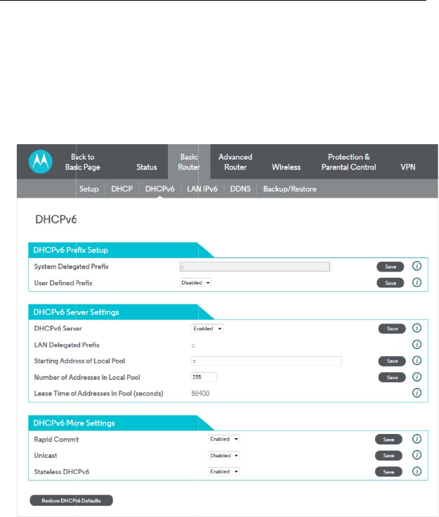
5.2.3 D
H
Choose Bas
This page a
l
modifying th
e
press Save
s
MG7540 Cable
r
ough 192.168.0.9 can
b
ess conflict with the DH
C
s
sed to CPEs behind th
e
H
CPv6
ic Router > DHCPv6 , a
Figure 13 DHCPv6
c
l
lows configuration of th
e
e
System Delegated Pre
f
s
o that the system can c
a
Modem User Manual
20
b
e used as hard-coded I
C
P pool. Configured WI
N
e
CM/RG via DHCP.
nd the following page ap
c
onfiguration
e
internal DhcpV6 serve
f
ix, set the System Dele
g
a
lculate its LAN Delegat
e
P addresses with no
N
S server addresses
pears.
r for the LAN. When
g
ated Prefix first, and
e
d Prefix.
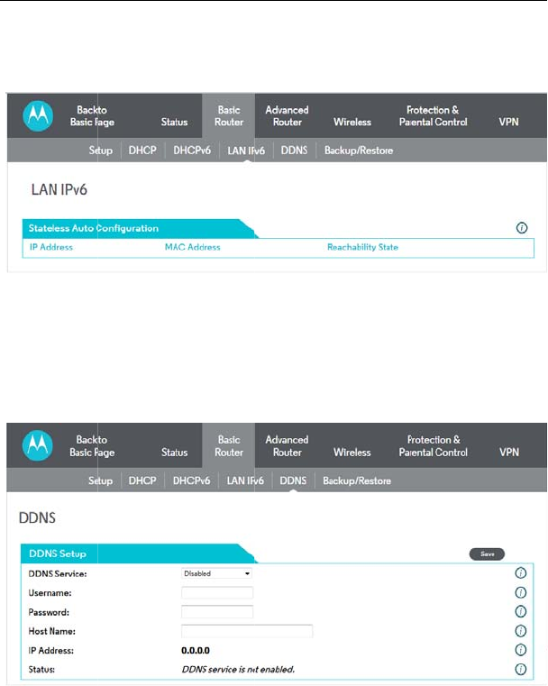
5.2.4 L
A
Choose Basic
This page di
s
5.2.5 D
D
Choose Basic
This page is
address to
b
easily conta
c
MG7540 Cable
A
N IPv6
Router> LAN IPv6 and
t
Figure 14 LAN IPv6
s
plays information relate
d
D
NS
Router > DDNS , and th
Figure 15 DDNS co
n
used to configure DDN
S
b
e aliased to a static, pr
e
c
ted by other hosts on
Modem User Manual
21
t
he following page appe
a
information
d
to IPv6 on the LAN.
e following page appear
s
n
figuration
S
. Dynamic DNS (DDNS
)
e
-defined host name so
the internet even if its
I
a
rs.
s
.
)
allows a dynamic IP
that the host can be
I
P address changes.
The CM/RG
service (http
To activate t
h
1. Go to th
e
service. Y
o
host name f
o
assigned.
Y
WAN IP add
WAN IP Add
2. Enter yo
u
the service
b
and click Sa
v
3. The DD
N
changes so
t
The current
s
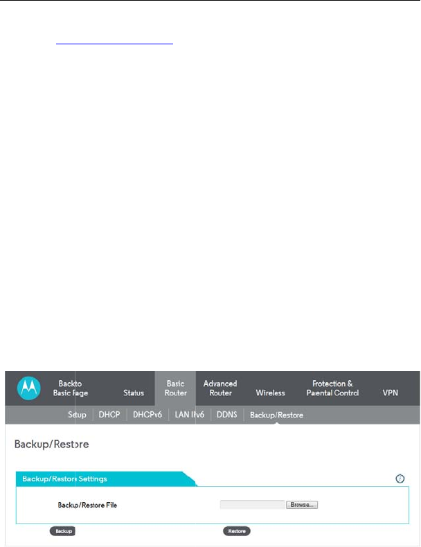
5.2.6 Ba
Choose Basic
In this page,
You can th
e
MG7540 Cable
supports a dynamic D
N
://www.dyndns.com/).
h
e DDNS client:
e
Dynamic DNS website
o
u will create a usernam
o
r your server, and the d
y
Y
ou will also be asked f
o
ress that has been assig
ress on the Basic Route
r
u
r account information o
n
b
y selecting www.DynDN
v
e.
N
S client will notify the
D
t
hat your chosen host na
m
s
tatus of the service is s
h
ckup/Restore
Router > Backup
/
Rest
o
Figure 16 Backup
/
R
e
you can save the curre
n
e
n later restore these
Modem User Manual
22
N
S client compatible wit
and create an account
f
e and password, and b
e
y
namic DNS domain to w
o
r
y
our host’s current IP
ned to your CM/RG duri
n
r
/ Setup web page.)
n
the Basic Router/ DD
N
S.org from the DDNS S
e
D
DNS service whenever
m
e will be resolved prop
e
h
own at the bottom of th
e
o
re and the following pa
g
e
store setup
n
t CM/RG configuration s
settings if you need
h the Dynamic DNS
f
or the Dynamic DNS
e
asked to choose a
hich your host will be
address. This is the
n
g provisioning. (See
N
S web page, enable
e
rvice drop-down list,
the WAN IP address
e
rly by inquiring hosts.
e
DDNS web page.
e appears.
ettings to a local PC.
restore a particular
configuratio
n
undesirable
e
To back up t
h
To restore a
locate the
f
saving.) O
n
Note that on
c
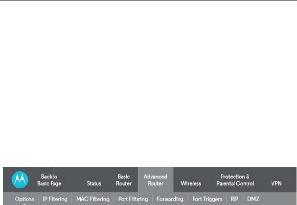
5.3 Adv
a
Choose Adva
n
below.
5.3.1 O
p
Choose Adva
n
MG7540 Cable
n
, or to recover from ch
a
e
ffect.
h
e current configuration,
previous configuration, c
f
ile. (Usually Gateway
S
n
ce the file has been l
o
c
e the settings are resto
r
a
nced Router
n
ced Router and the su
Figure 17 Submenu
s
p
tions
n
ced Router > Options
t
Modem User Manual
23
a
nges you may have ma
click Backup and follow
t
c
lick Browse and use the
S
ettings.bin, unless y
o
o
cated, click Restore to
r
ed, the device will reboo
t
bmenus of Advanced
R
s
of Advanced Router
t
o display the following p
a
de that have had an
t
he prompts.
navigation window to
o
u rename it before
resto
r
e the settings.
t
.
R
outer are shown as
a
ge.
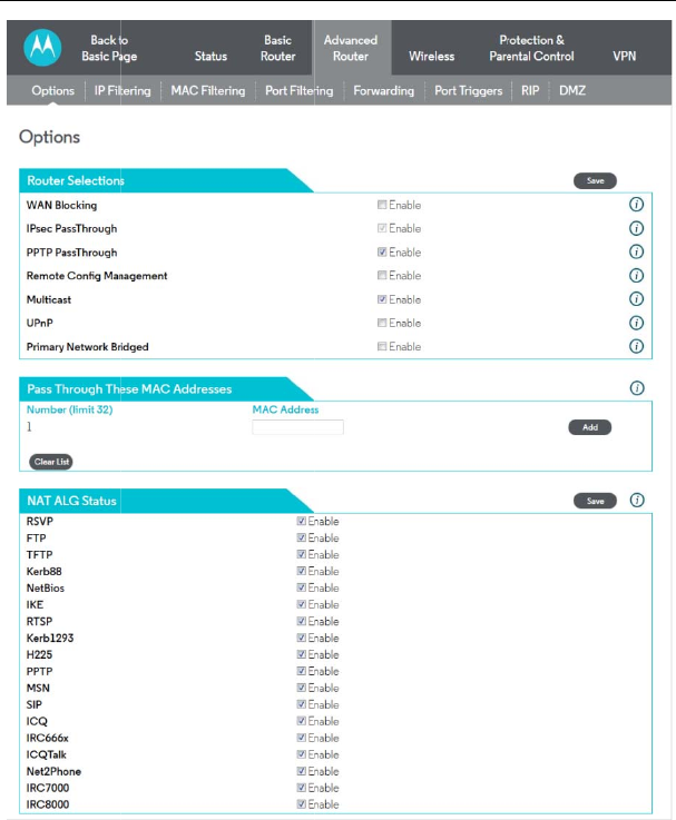
This page allo
w
the appropriat
e
selections, cli
c
without a syste
WAN Blocking
MG7540 Cable
Figure 18 Options c
o
w
s you to configure the
a
e
check box until it is “
c
c
k on the Save button.
m reset.
prevents your cable mo
d
Modem User Manual
24
o
nfiguration
a
ccessible features.To e
n
c
hecked”. When you a
r
These features can b
e
d
em/router or the device
s
n
able a feature, click
r
e satisfied with your
e
modified on the fly
s
behind it from being
visible from th
e
address and la
IpSec PassTh
r
cable modem/
r
on the Internet
.
PPTP (Point-t
o
VPN software
communicate
s
Remote Conf
i
IPAddress›:80
8
your Cable
M
Multicast :Allo
w
LAN behind yo
UPnP: If you a
r
Primary Netw
o
Addresses.
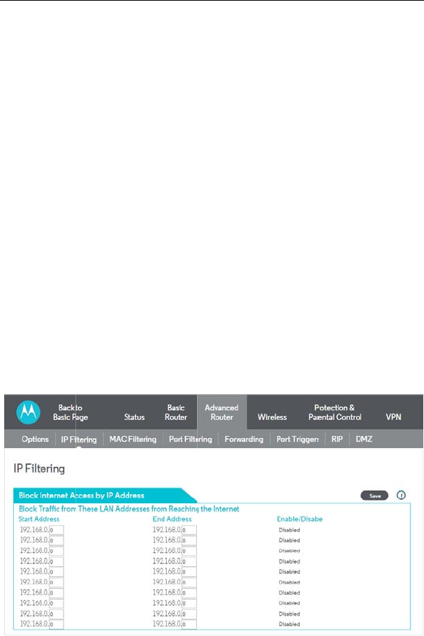
5.3.2 IP
Choose Adva
n
MG7540 Cable
e
Internet. This makes it
unch an attack on your
p
r
ough enables a VPN d
r
outer and running IpSe
c
.
o
-Point Tunneling Proto
c
located behind your
c
s
uccessfully with endpoin
i
g Management: Whe
n
8
0/ to administer your
C
M
odem/Router's WAN
w
s multicast specific traf
f
ur Cable Modem/Router
r
e running an application
rk Bridged: Enable or D
i
Filterin
g
n
ced Router> IP Filterin
g
Modem User Manual
25
difficult for hackers to d
i
p
rivate LAN.
d
evice or VPN software
c
to communicate succe
s
c
ol) PassThrough enabl
e
c
able modem/router an
ts on the Internet.
n
enabled, navigate
t
C
able Modem/Router re
m
IP address on the
f
ic to be passed to and f
r
that requires UPnP, Ena
i
sable the feature Pass
T
g
to display the following
i
scover your WAN IP
located behind your
s
sfully with endpoints
e
s a VPN device or
d running PPTP to
t
o http://‹CM WAN
m
otely. You can find
B
asic Setup page.
r
om the PCs on your
ble UPnP.
T
hrough These MAC
page.
This page all
o
access to the
W
By entering st
a
PCs are deni
e
(Least-signific
a
automatically f
r
also check the
settings comm
o
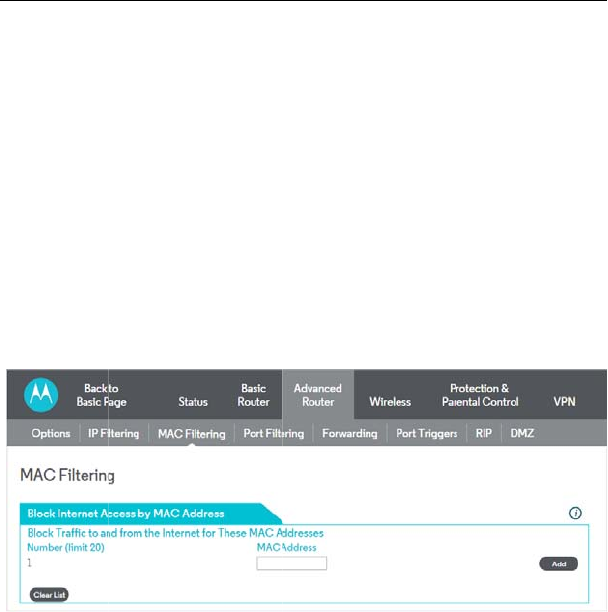
5.3.3 M
A
Choose Adva
n
This page is u
s
via their MAC
a
This is useful f
o
unlike its IP a
various addres
s
5.3.4 Po
r
Choose Adva
n
MG7540 Cable
Figure 19 IP Filterin
g
ws you to configure th
e
W
AN by specifying those
a
rting and ending IP ad
d
e
d access to the WAN.
a
nt byte) of the IP addre
s
r
om the CM/RG IP addr
e
“enable” box and click
S
o
nly used but not have t
h
A
C Filtering
n
ced Router > MAC Filt
e
Figure 20 MAC Filte
r
s
ed to prevent PCs from
s
a
ddress
o
r the fact that the MAC
a
ddress which can be a
s
es over time.
r
t Filterin
g
n
ced Router> Port Filte
r
Modem User Manual
26
g
configuration
e
CM/RG to prevent lo
c
IP addresses that shoul
d
d
ress ranges, you can
c
Note that you only ne
e
s
s; the upper bytes of th
e
ss. To activate the IP ad
S
ave. The enable box all
o
h
em active.
e
ring to display the follo
w
r
ing configuration
s
ending outgoing TCP/U
D
a
ddress of a specific NIC
ssigned via DHCP ser
v
r
ing to display the followi
c
al PCs from getting
d
be filtered.
c
onfigure which local
e
d to enter the LSB
e IP address are set
dress filter, you must
o
ws you to store filter
w
ing page.
D
P traffic to the WAN
card never changes,
v
er or hard-coded to
ng page.
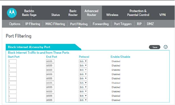
This page is u
s
on specific IP
p
By specifying
a
traffic is allowe
are blocked fo
r
For instance, i
f
HTTP sites (or
80, the “Protoc
o
5.3.5 Fo
r
Choose Ad
v
MG7540 Cable
Figure 21 Port Filteri
s
ed to prevent PCs from
s
p
ort numbers.
a
starting and ending po
d
out to the WAN on a p
e
r
ALL PCs and this setti
n
f
you would like to bloc
k
“web surfing”), you wou
o
l” to TCP, check the “E
n
r
wardin
g
v
anced Router > Forwa
r
Modem User Manual
27
ng configuration
s
ending outgoing TCP/U
D
rt range, you may deter
m
er
-port basis. Note the
s
n
g is not IP address or M
k
all PCs on the private
ld set the “Start Port” to
n
abled” box, and click Sa
v
r
ding to display the follo
w
D
P traffic to the WAN
m
ine what TCP/UDP
s
pecified port ranges
AC address specific.
LAN from accessing
80, the “End Port” to
v
e.
w
ing page.
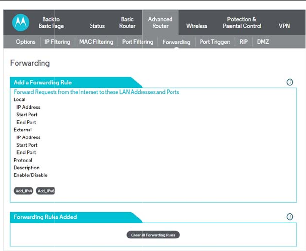
This allows fo
r
FTP servers,
m
table of comm
o
Forwarding all
o
the mapping o
f
To specify a
m
forwarded loc
a
If only a single
and “end” loca
t
supplied on th
e
If both external
a mandatory f
number is us
e
internal port nu
MG7540 Cable
Figure 22 Forwardin
g
r
incoming requests on
s
m
ail servers, etc. so they
o
nly used port numbers i
s
o
ws you to run a publicl
y
f
TCP/UDP ports to a loc
a
m
apping, you must ente
r
lly, and the IP address t
o
port specification is desi
t
ions for that IP address.
e
page for convenience.
and Local/internal port
n
ield and the external p
o
e
d, the RG will perform
mber.
Modem User Manual
28
g
configuration
s
pecific port numbers t
o
can be accessible from
s
also provided.
y
accessible server on t
h
a
l PC
r
the range of port nu
m
o which traffic to those
p
red, enter the same port
A table of commonly
u
n
umbers are present, the
o
rt number is optional.
a translation from ext
e
o
reach web servers,
the public internet. A
h
e LAN by specifying
m
bers that should be
p
orts should be sent.
number in the “start”
u
sed Port numbers is
Local port number is
If the external port
e
rnal port number to
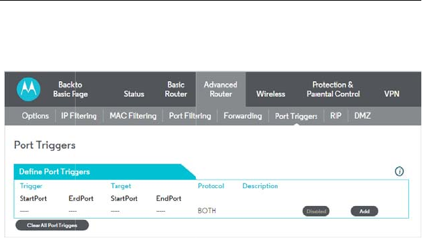
5.3.6 Po
r
Choose Adva
n
Port Triggers a
open all the ti
m
number set in
t
opened for inc
outgoing traffi
c
Range” ports
w
applications (e
chat programs
constantly or
e
potential hack
e
5.3.7 RI
P
Choose Adva
n
MG7540 Cable
r
t Tri
gg
ers
n
ced Router > Port Trig
g
Figure 23 Port Trigg
e
re similar to Port Forwar
m
e. When the CM/RG
t
he “Trigger Range”, the
oming (or sometimes re
c
is detected on the “Trig
w
ill close. This is a safe
r
.g. video conferencing
p
, etc.) because they a
r
e
rroneously left open vi
e
rs to discover.
P
Setup
n
ced Router> RIP Setu
p
Modem User Manual
29
g
ers to display the follo
w
e
rs configuration
ding except that they ar
e
detects outgoing data
o
resulting ports set in th
e
e
ferred to as bi-direction
a
g
ger Range” ports for 10
r
method for opening sp
e
p
rograms, interactive ga
r
e dynamically triggered
a the router administra
t
p
to display the following
p
w
ing page.
e
not static ports held
o
n a specific IP port
e
“Target Range” are
a
l ports) data. If no
minutes, the “Target
e
cific ports for special
ming, file transfer in
and not held open
t
or and exposed for
p
age.
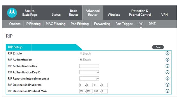
RIP (Router In
f
best known an
d
congestion an
d
NOTE: RIP
m
Addressing m
o
and the set the
controlled via t
h
information fro
m
RIP is a protoc
o
and CMTS).
T
CMTS settings
To enable the
C
as the RIP Aut
h
1.) To turn on
R
2.) To specify
a
key name = a
s
3.) To specify
a
key number =
a
4.) To change
t
interval by def
a
MG7540 Cable
Figure 24 RIP confi
g
f
ormation Protocol) is u
s
d
quickest route to given
d
delays.
m
essaging will only be
o
de on the Basic – Setu
p
Wan IP network inform
a
h
e ISP. RIP Authentica
t
m
the end user to preven
o
l that requires negotiati
o
T
he ISP would normally
s
to match the configurati
o
C
M/RG to perform RIP,
d
h
entication Key and 1 as
R
IP MD5 Authentication,
c
a
RIP MD5 Authenticatio
n
s
tring value to match CM
T
a
RIP MD5 Auth Key ID, t
y
a
number to match the C
M
t
he RIP annoucement in
a
ult = 30 seconds
Modem User Manual
30
g
uration
s
ed in WAN networks to
destination addresses to
sent upstream when
r
p
page. You must enable
a
tion! RIP is normally a
f
t
ion Keys and IDs are n
o
t unauthorized RIP setti
n
o
n from both sides of the
s
et this up because of th
e
o
n in the CM/RG.
d
o the following (this ex
a
the Key ID):
c
heck the “Enable” box.
n
Key String, type “BRC
M
T
S key name value
y
pe “1”
M
TS key number value
terval, type in a number
identify and use the
help reduce network
r
unning in Static IP
Static IP Addressing
f
unction that is tightly
o
rmally held as secret
n
gs.
network (i.e. CM/RG
e
ir knowledge of their
a
mple uses BRCMV2
M
V2” for this example.
in seconds.reporting

MG7540 Cable Modem User Manual
31
5.) To specify a RIP unicast destination IP address, enter the IP address and subnet
mask.
To enable the CMTS for RIPv2 with MD-5 authentication (Cisco uBR example shown
below):
1.) The following steps go through configuring RIPv2 for a Cisco CMTS. The network
number used in this configuration will vary from network to network so use the
network number that matches your set-up.
7223#configure terminal
7223(config)#key chain ubr
7223(config-keychain)#key 1
7223(config-keychain-key)#key-str BRCMV2
7223(config-keychain-key)#exit
7223(config-keychain)#exit
7223(config)#router rip
7223(config-router)#ver 2
7223(config-router)#no validate-update
7223(config-router)#passive-interface cable 2/0
7223(config-router)#network 10.0.0.0
7223(config-router)#exit
7223(config)#inter cable 2/0
7223(config-if)#ip rip receive ver 2
7223(config-if)#ip rip authentication mode md5
7223(config-if)#ip rip authentication key-chain ubr
7223(config-if)#exit
7223(config)#exit
In this example, we have named the key chain ‘ubr’. This was chosen arbitrarily. You
can use any name you like as long as you specify the correct name when specifying
which key chain to use for RIPv2 authentication.
2.) The next step is enable RIP debugging to ensure that the CMTS is receiving and
authenticating messages from the residential gateway.
7223#debug ip rip
RIP protocol debugging is on

MG7540 Cable Modem User Manual
32
7223#term mon
The CMTS is now configured to accept RIPv2 messages. If the CM/RG is registered
on the CMTS, you should see messages that are similar to the message below:
00:28:41: RIP: received packet with MD5 authentication
00:28:41: RIP: received v2 update from 10.24.81.148 on Cable2/0
00:28:41: 10.24.81.0/24 via 10.24.81.148 in 1 hops
The CM/RG has broadcast that is connected to the network 10.24.81.0/24 through
the interface 10.24.81.148. This information is not very useful to the CMTS because it
already knows that the network 10.24.81.0/24 is connected directly to one of its
interfaces (Cable2/0). It ignores this message and doesn’t add any information to the
IP routing table. Here is the IP routing table after the CMTS has received RIPv2
messages:
7223#sh ip route
Codes: C - connected, S - static, I - IGRP, R - RIP, M - mobile, B - BGP
D - EIGRP, EX - EIGRP external, O - OSPF, IA - OSPF inter area
N1 - OSPF NSSA external type 1, N2 - OSPF NSSA external type 2
E1 - OSPF external type 1, E2 - OSPF external type 2, E - EGP
i - IS-IS, L1 - IS-IS level-1, L2 - IS-IS level-2, ia - IS-IS inter area
* - candidate default, U - per-user static route, o - ODR
P - periodic downloaded static route
Gateway of last resort is 10.24.95.17 to network 0.0.0.0
10.0.0.0/8 is variably subnetted, 3 subnets, 2 masks
C 10.24.80.0/24 is directly connected, Cable2/0
C 10.24.81.0/24 is directly connected, Cable2/0
C 10.24.95.16/28 is directly connected, FastEthernet0/0
S* 0.0.0.0/0 [1/0] via 10.24.95.17
In the example above, the CM/RG was set up to send RIPv2 messages to the CMTS.
The CMTS was also set up to receive these messages.
5.3.8 DMZ Host
Choose Advanced Router > DMZ Host to display the following page.
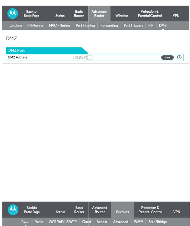
DMZ (De-milit
a
allows you to
translate to a
k
sub-network t
h
public Internet.
You may confi
g
PC’s using “pr
o
correctly with
s
specific PC is
s
the needed ap
p
though still pro
t
5.4 Wire
Choose Wirel
e
5.4.1 Ba
Choose Wirel
e
MG7540 Cable
Figure 25 DMZ Host
a
rized Zone) hosting (al
s
specify the “default” re
c
k
nown local PC. This c
a
h
at sits between the tru
s
g
ure one PC to be the
D
o
blem” applications that
u
s
pecific port triggers or p
o
s
et as a DMZ Host, reme
m
p
lication, since this PC wi
t
ected from Denial of Se
r
less
e
ss and the submenus o
f
Figure 26 The subm
e
sic
e
ss > Basic to display th
e
Modem User Manual
33
configuration
s
o commonly referred t
o
c
ipient of WAN traffic th
a
n also be described as
s
ted internal private LA
N
D
MZ host. This setting
u
se random port number
s
o
rt forwarding setups m
e
m
ber to set this back to “
0
i
ll be effectively exposed
r
vice (DoS) attacks via th
f
Wireless are shown as
e
nus of Wireless
e
following page.
o
as “Exposed Host”)
at NAT is unable to
a computer or small
N
, and the untrusted
is generally used for
s
and do not function
e
ntioned earlier. If a
0
” when finished with
to the public Inte
r
net,
e Firewall.
below.
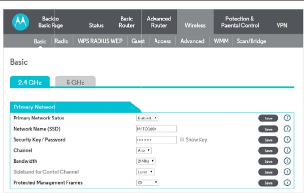
This page allo
w
Primary Netw
o
Enable or Disa
the primary ne
t
Network Nam
e
Sets the Netw
o
ASCII charact
e
WPA-PSK / W
P
Motorola assig
This security k
e
If you want, yo
clicking the Sa
v
Selects the co
n
on the selecte
d
Bandwidth:
802.11b/g cha
n
wide. There ar
e
MG7540 Cable
Figure 27 Basic con
f
w
s you to configure the P
o
rk:
ble the primary network.
t
work is disabled.
e
(SSID):
o
rk Name (also known a
s
e
r string.
P
A2-PSK Security Key
/
ned your device a uniq
u
e
y is displayed here.
u can change the securi
t
v
e button. Channel:
n
trol channel for AP ope
r
d
country as presented in
n
nels are only 20 MHz
w
e
some backward comp
a
Modem User Manual
34
f
iguration
rimary Wireless Network
Guest networks may still
s
SSID) of the primary n
e
/
Password:
u
e Security Key (or Pas
s
t
y key by entering the n
e
r
ation. The list of availab
.
w
ide, but 802.11n chan
n
a
tibility issues with 40 M
.
be operational when
e
twork. This is a 1-32
s
word) at the factory.
e
w key here and then
le channels depends
n
els may be 40 MHz
Hz channels though.
These issues
a
(802.11b/g) de
v
Sideband for
C
Whether the 2
channel. Cha
n
example (in th
e
the control ch
a
allow the lowe
r
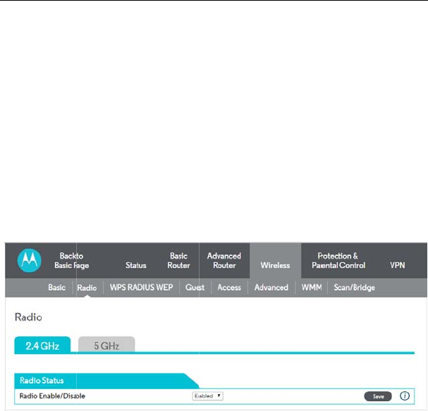
5.4.2 R
a
Choose Wirel
e
Radio Enable
/
Allows the wir
e
5.4.3 W
P
Choose Wirel
e
MG7540 Cable
a
re more likely to be en
c
v
ices may be operating
u
C
ontrol Channel (40 M
H
0 MHz control channel
n
ges to this setting m
a
e
2.4 GHz band), if the
u
a
nnel, then the lowest co
n
r
20 MHz for data.
a
dio
e
ss > Radio to display th
e
Figure 28 Radio con
/
Disable:
e
less interface to be ena
b
P
S
_
RADIUS
_W
e
ss > WPS_RADIUS_W
E
Modem User Manual
35
c
ountered in the 2.4 GH
z
u
sing 20 MHz channels.
H
z only):
uses the upper or lowe
r
a
y change the control
c
u
pper 20 MHz is selecte
d
n
trol channel available
w
e
following page.
figuration
b
led and disabled.
W
EP
E
P to display the followin
g
z
band where legacy
r
half of the 40 MHz
c
hannel setting. For
d
as the sideband for
w
ould be channel 5 to
g
page.
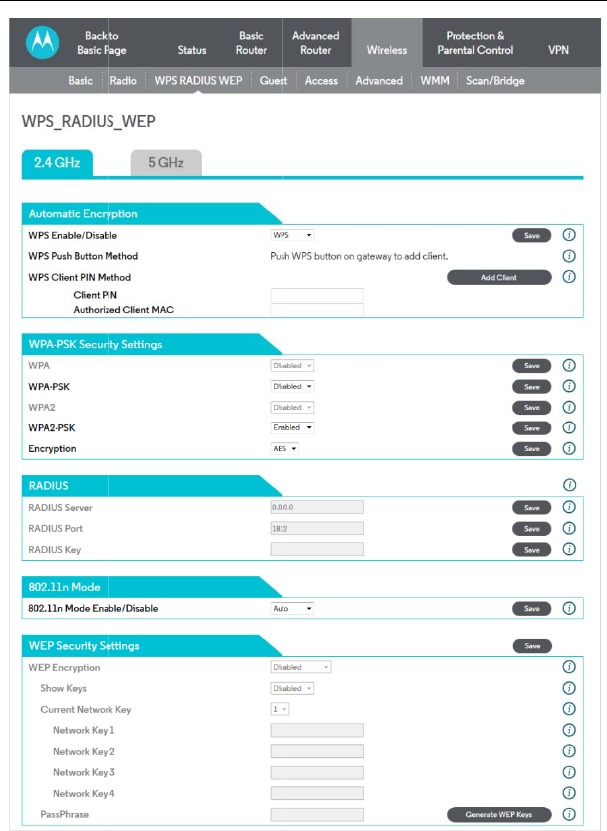
This page allo
w
MG7540 Cable
Figure 29 WPS_RA
D
w
s you to configure the
W
Modem User Manual
36
D
IUS_WEP configuration
W
PS_RADIUS_WEP

MG7540 Cable Modem User Manual
37
WPS Enable/Disable:
WPS stands for Wi-Fi Protected Setup. WPS provides two methods to automatically
distribute wireless keys to clients that support this feature, described below. For the
record, as of July, 2015, Apple devices did not support WPS.
WPS Client PIN Method:
On your client device, run a utility to generate a WPS PIN.
Copy the PIN that the client generates and enter it here, then press the Save button.
Once this process is complete, your cable modem/router will display the results, or it
will time out after about two minutes.
Note that this method will change the default SSID and key for your network.
WPA:
Wi-Fi Protected Access is a slightly older and less secure algorithm for securing a
wireless network. This is the Enterprise variant that requires configuration of a
RADIUS server.
WPA-PSK:
The Pre-Shared Key mode of the WPA algorithm which does not require use of a
RADIUS server. This is also known as WPA Personal. WPA and WPA-PSK cannot be
used at the same time.
WPA2:
An advanced form of WPA that is more secure. This is the Enterprise mode of WPA2
which requires the use of a RADIUS server. WPA2 and WPA may be used at the
same time to provide backward compatibility with devices that do not support WPA2.
WPA2-PSK:
The Pre-Shared Key mode of WPA2, also known as WPA2 Personal.WPA2 and
WPA2-PSK cannot be used at the same time. WPA2-PSK and WPA-PSK may be
used at the same time to provide backward compatibility with devices that do not
support WPA2.
Encryption:
Select the desired encryption protocol for your network. The default is TKIP+AES.
RADIUS:
Disable WPA-PSK / WPA2-PSK and Enable WPA / WPA2 to un-gray out RADIUS
settings.
802.11n Mode
Set this para
m
default value i
s
WEP Encrypti
o
Disabled and
g
to OFF to un-g
r
Network Key
1
When WEP e
characters or 1
hexadecimal d
i
Current Netw
o
This selects th
e
PassPhrase:
Enter a 10 or
Network Keys
1
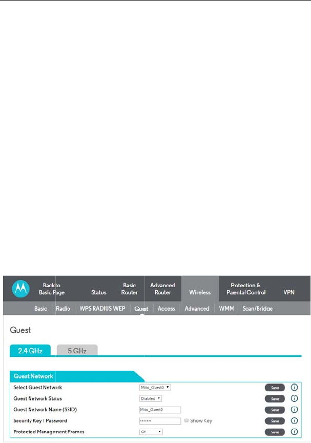
5.4.4 G
u
Choose Wirel
e
MG7540 Cable
:
m
eter to OFF to force 8
0
s
Auto.
o
n:
g
rayed out by default. If
y
r
ay out, and then Enable
1
thru Network Key 4:
ncryption is enabled,
s
0 hexadecimal digits for
gits for a 128-bit key.
o
rk Key:
e
Network Key used for t
r
26 character string, th
1
- 4.
u
est
e
ss > Guest to display th
e
Figure 30 Guest con
Modem User Manual
38
0
2.11g mode (required t
o
y
ou need WEP Encrypti
o
this parameter.
s
ets the static WEP ke
a 64-bit key. Enter 13 A
S
r
ansmissions. Select 1 -
4
en press Generate WE
e following page.
figuration
o
enable WEP). The
o
n, set 802.11n Mode
ys. Enter 5 ASCII
S
CII characters or 26
4
(default 1).
P Keys to generate

MG7540 Cable Modem User Manual
39
The page allows you to configure a secondary guest network on the wireless
interface.
Select Guest Network:
This is a pull down of Moto_Guest0 to Moto_Guest7.
Guest Network Status:
Enable or Disable the Guest Network selected above.
Guest Network Name (SSID):
Either accept the default Network Name, or change the name by entering the new
name here, and clicking the Save button.
WPA-PSK / WPA2-PSK Security Key / Password:
Enter a key here, and click the Save button to save it.
5.4.5 Access
Choose Wireless > Access to display the following page.
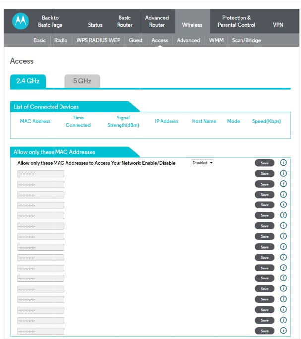
This page all
o
network. It als
o
point.
Connected Cl
i
A list of conn
e
network, it is a
d
it is removed f
r
MG7540 Cable
Figure 31 Access c
o
o
ws you to control whic
h
o
provides information ab
i
ents:
e
cted wireless clients.
W
d
ded to the list; when a
c
r
om the list. For each cli
e
Modem User Manual
40
o
nfiguration
h
wireless clients can
a
out wireless clients conn
W
hen a client connect
s
c
lient leaves (disassociat
e
e
nt, the age (in seconds
a
ccess your wireless
ected to your access
(associates) to the
e
s) from the network,
), estimated average

MG7540 Cable Modem User Manual
41
receive signal strength (in dBm), IP address, and host name are presented. The age
is the amount of time elapsed since data was transmitted to or received from the
client.
5.4.6 Advanced
Choose Wireless > Advanced to display the following page.
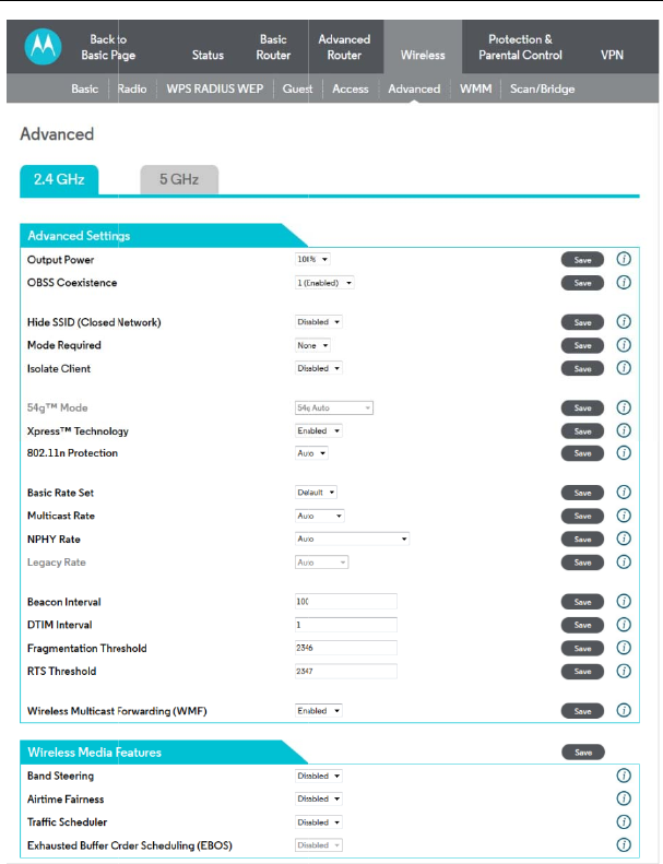
This page allo
w
Output Power
Control the ran
MG7540 Cable
Figure 32 Advanced
w
s you to configure adva
n
:
ge of the AP by adjustin
g
Modem User Manual
42
configuration
n
ced wireless settings.
g
the radio output power.

MG7540 Cable Modem User Manual
43
OBSS Coexistence:
OBSS coexistence refers to the ability of your device to support 20 MHz clients within
40 MHz channels. It also allows your device to reduce interference from nearby 20
MHz devices that are interfering with part of your device's 40 MHz channel.
Hide SSID (Closed Network):
When this feature is enabled, the SSID is not broadcast. Therefore, only devices that
already know the SSID will be able to connect.
Mode Required:
Select None, HT or ERP, where HT and ERP refer to High Throughput and Extended
Rate PHY, respectively. These settings determine how your network interacts with
older (802.11b/g) and newer (802.11n) wireless clients. Most users will leave this at
the default setting of None.
Isolate Client:
When this feature is enabled, wireless clients are isolated from your wired network
and from each other. They can only access the Internet, but not any servers or other
devices on your network.
54g™ Mode:
Sets the network mode for legacy 802.11g & 802.11b networks. To un-gray out this
selection, under the 2.4GHz tab in WPS_RADIUS_WEP, Disable 802.11n Mode.
Choices are 54g Auto, 54g only, 54g Performance, 54g LRS, and 802.11b Only. 54g
Auto accepts 54g, 802.11g, and 802.11b clients, but optimizes performance based on
the type of clients connected. 54g Performance accepts only 54g™ clients and
provides the highest throughout; nearby 802.11b networks may have degraded
performance. 54g LRS interoperates with the widest variety of 54g™, 802.11g, and
802.11b clients. 80211b accepts only 802.11b clients.
Xpress Technology:
Enable Broadcom proprietary method of block frame acknowledgement for 802.11g
frames. This feature may improve throughput, but may cause problems.
Afterburner Technology
This feature removes the need for the acknowledgement of data frames. It may
improve throughput, but may cause problems.

MG7540 Cable Modem User Manual
44
802.11n Protection:
802.11n Protection protects legacy 802.11b&g devices that are within range of your
cable modem/router. This feature is enabled (Auto) by default.
In some environments with no legacy devices, you may improve performance by
disabling this feature.
Basic Rate Set:
Determines which rates are advertised as “basic” rates. Default uses the driver
defaults. Sets all available rates as basic rates.
Multicast Rate:
This is the rate at which you send out multicast packets to stations. Multicast packets
are not acknowledged.
NPHY Rate:
Choose 802.11n rate to be applied to all unicast packets.
Legacy Rate:
“N” mode must be off on the “radio” webpage for this control to be active. When
active the user can force the rate in which the AP will operate.
Beacon Interval:
Sets the beacon interval in milliseconds for the AP. The default is 100, which is fine
for nearly all applications.
DTIM Interval:
Sets the wakeup interval for clients in power-save mode. When a client is running in
power save mode, lower values provide higher performance but result in decreased
client battery life, while higher values provide lower performance but result in
increased client battery life.
Fragmentation Threshold:
Sets the fragmentation threshold. Packets exceeding this threshold will be
fragmented into packets no larger than the threshold before packet transmission.
RTS Threshold:
Sets the RTS threshold. Packets exceeding this threshold will cause the AP to
perform an RTS/CTS exchange to reserve the wireless medium before packet
transmission.
Wireless Mult
i
Multicast invol
v
a video stream
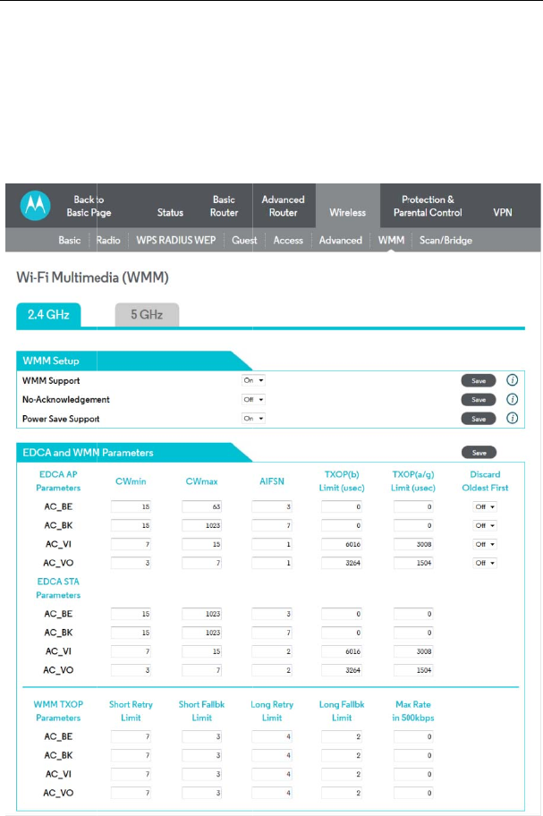
5.4.7 W
M
Choose Wirel
e
MG7540 Cable
i
cast Forwarding (WMF
v
es sending the same pa
c
.
M
M
e
ss > WMM to display th
e
Modem User Manual
45
):
c
kets to two or more end
p
e
following page.
p
oints, for example of

MG7540 Cable Modem User Manual
46
Figure 33 WMM configuration
This page allows you to configure WiFi Multi-Media (WMM). WMM is an
implementation of Quality of Service (Qos) which is defined by the IEEE standard
802.11e.
WMM Support:
Sets WMM support. Choices are Auto, On, or Off. If enabled (Auto or On), the WME
Information Element is included in beacon frame.
No-Acknowledgement:
Sets No-Acknowledgement support. Choices are On or Off. When enabled,
acknowledgments for data are not transmitted.
Power Save Support:
Sets Power Save support. Choices are On or Off. When Power Save is enabled, the
AP queues packets for STAs that are in power-save mode. Queued packets are
transmitted when the STA notifies AP that it has left power-save mode.
EDCA AP Parameters:
Specifies the transmit parameters for traffic transmitted from the AP to the STA for the
four Access Categories: Best Effort (AC_BE), Background (AC_BK), Video (AC_VI),
and Voice (AC_VO). Transmit parameters include Contention Window (CWmin and
CWmax), Arbitration Inter Frame Spacing Number (AIFSN), and Transmit
Opportunity Limit (TXOP Limit).
There are also two AP-specific settings: Admission Control and Discard Oldest First.
Admission control specifies if admission control is enforced for the Access Categories.
Discard Oldest First specifies the discard policy for the queues. On discards the
oldest first; Off discards the newest first.
EDCA STA Parameters:
Specifies the transmit parameters for traffic transmitted from the STA to the AP for the
four Access Categories: Best Effort (AC_BE), Background (AC_BK), Video (AC_VI),
and Voice (AC_VO). Transmit parameters include Contention Window (CWmin and
CWmax), Arbitration Inter Frame Spacing Number (AIFSN), and Transmit
Opportunity Limit (TXOP Limit).
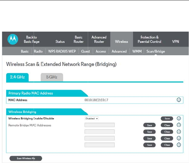
5.4.8 Sc
a
Choose Wirel
e
This page allo
w
Distribution S
y
points togethe
r
Wireless Brid
g
This setting en
a
Remote Bridg
e
Table of remo
t
Up to 4 remot
e
AP’s MAC add
r
5.5 Prot
e
Choose Prote
c
Control are sh
MG7540 Cable
a
n/Bridging
e
ss > Scan/Bridging to
d
Figure 34 Scan/Brid
g
w
s you to configure wirel
e
y
stem (WDS). Bridging
a
r
to form a single networ
k
g
ing:
a
bles or disables wireles
s
e
s:
t
e bridge MAC address
e
e
bridges may be connec
t
r
ess (see section 0) on t
h
e
ction & Parenta
l
c
tion & Parental Contro
l
own as below.
Modem User Manual
47
d
ispla
y
the following pag
e
g
ing configuration
e
ss bridging, which is al
s
a
llows you connect mul
t
k
using wireless point-to-
p
s
bridging.
e
s authorized to establi
s
t
ed. Typically, you will al
s
h
e remote bridge, too.
l
Control
l
and the submenus of P
r
e
.
s
o known as Wireless
t
iple wireless access
p
oint links.
s
h a wireless bridge.
s
o have to enter your
r
otection & Parental
5.5.1 Fi
r
Choose Prote
c
page.
This page is u
CM/RG from t
h
The “low” setti
n
invalid packets
drop a packet
u
are listed on t
h
access to eve
n
MG7540 Cable
Figure 35 su
r
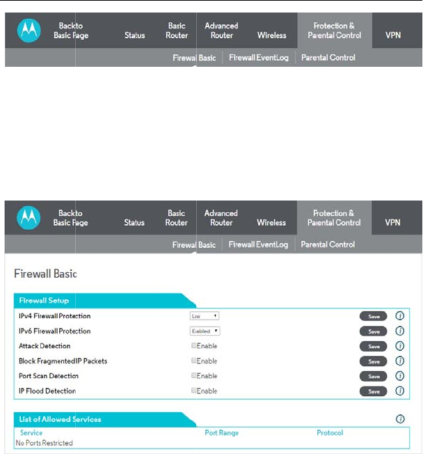
ewall Basic
c
tion & Parental Cont
r
Figure 36 Fire
w
sed to block or exclusi
v
h
e WAN to the LAN.
n
g does not block any s
e
and well known attacks.
u
nless it is on a specific
h
e same page. The “hi
g
n
fewer services. The “off
”
Modem User Manual
48
bmenus of Protection & P
a
r
ol> Firewall Basic to
d
w
all Basic configuration
v
ely allow different types
e
rvices/ports, however it
The “medium” setting wil
port of allowed services;
g
h” setting is similar to
“
”
setting allows all traffic
t
a
rental Control
d
isplay the following
of data through the
does protect against
l cause the firewall to
the allowed services
“
medium”, but allows
t
o pass.
Block Fragme
n
the firewall.
P
both the LAN
originating on
b
activate any o
f
without a CM/
R
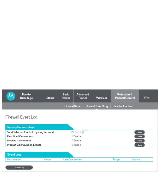
5.5.2 Ev
Choose Prote
c
page.
Configure the
r
and/or set up
e
logged and/or
y
Syslog server,
where you wa
n
to take effect.
N
you have sele
c
MG7540 Cable
n
ted IP packets prevent a
l
P
ort Scan Detection dete
c
and WAN. IP Flood
D
b
oth the LAN and WAN.
f
the checkbox items. All
R
G reboot.
ent Log
c
tion & Parental Contro
l
Figure 37 Firewall E
v
r
outer to log a record of
e
mail alerts to warn of th
e
y
ou want to be warned a
if you have one. Third, e
n
n
t warnings to be sent, if
N
ote that you can view
t
c
ted at the bottom of the
p
Modem User Manual
49
l
l fragmented IP packets
f
c
ts and blocks port scan
a
D
etection detects and
b
The Save button must
b
of these settings can b
e
l >Firewall Event Log t
o
v
ent Log configuration
events to a local Syslog
e
events. First, select the
bout. Second, enter the
a
nter the email address a
n
applicable. Finally, click
t
he most recent entries
o
p
age.
f
rom passing through
a
ctivity originating on
b
locks packet floods
b
e clicked in order to
e
activated on-the-fly
o
display the following
server on your LAN,
events that you want
a
ddress of your local
n
d SMTP information
Save for the settings
o
f the log information
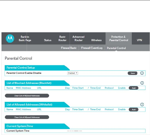
5.5.3 Pa
r
Choose Prote
c
page.
Parental Cont
r
addresses. If
y
those devices
Allowed Addre
s
only the Allow
e
List of Blocked
want to block t
o
need help fin
d
access you wa
enter the days
block (choose
b
MG7540 Cable
r
ental Control
c
tion & Parental Contr
o
Figure 38 Parental
C
r
ol: Parental Control l
e
y
ou define Blocked addr
e
can reach all websites
e
s
ses for particular devic
e
e
d Addresses.
Addresses: Enter the M
o
a particular site. (Chec
k
ing its MAC Address).
T
nt to block. Next, if you
w
and start and end time
s
b
oth if you're not sure). F
i
Modem User Manual
50
o
l > Parental Control to
C
ontrol configuration
e
ts you define lists of
e
sses for particular devi
c
e
xcept the Blocked add
r
e
s on your network, tho
s
AC Address of the devi
c
k
the user documentatio
n
T
hen enter the URL of
w
ant to block access onl
y
s
of the blocking. Next,
e
i
nally, select Enable and
display the following
blocked or allowed
c
es on your network,
r
esses. If you define
s
e devices can reach
c
e whose access you
n
for the device if you
the web site whose
y
during certain times
e
nter the Protocols to
click Save to activate
the entry.
Note that you
c
List of Allowed
access to a pa
help finding its
want to allow.
days and star
t
(choose both i
f
entry.
Note that you
c
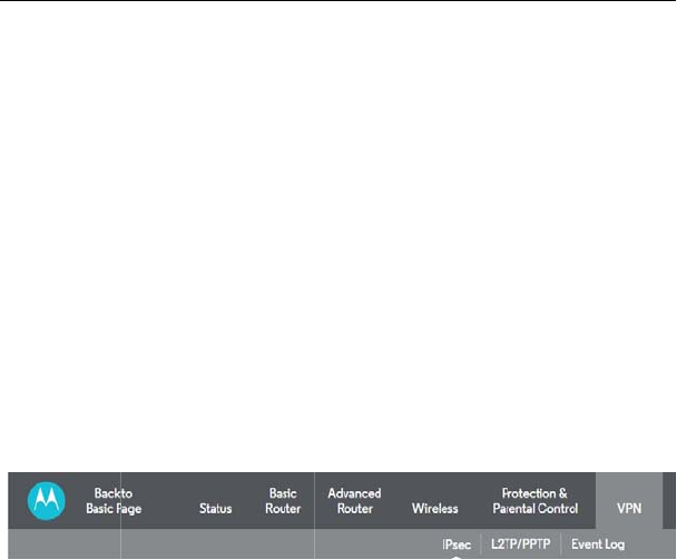
5.6 VPN
Choose VPN a
5.6.1 IP
S
Choose VPN >
MG7540 Cable
c
an Disable the entry te
m
Addresses: Enter the
M
r
ticular site. (Check the
u
MAC Address). Then en
t
Next, if you want to allo
w
t
and end times of the
f
you're not sure). Finall
y
c
an Disable the entry te
m
nd the submenus of
V
P
N
Figure 39 Submenu
s
S
ec
IPSec to display the foll
o
Modem User Manual
51
m
porarily if you may want
M
AC Address of the devi
c
u
ser documentation for t
h
t
er the URL of the web si
w
access only during c
e
access. Next, enter th
e
y
, select Enable and clic
k
m
porarily if you may want
N
are shown as below.
s
of VPN
o
wing page.
to re-Enable it later.
c
e you want to allow
h
e device if you need
t
e whose access you
e
rtain times enter the
e
Protocols to allow
k
Save to activate the
to re-Enable it later.
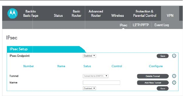
This page will
s
Tunnel:
This is a pull-d
to configure.
Name:
Enter a VPN n
a
5.6.2 L2
Choose
V
PN >
MG7540 Cable
Figure 40 IPSec con
s
how the status of config
u
o
wn list of VPN Names
d
a
me and click Add New
T
TP/PPTP
L2TP/PPTP to display t
h
Modem User Manual
52
figuration
u
red tunnels.
d
efined below. Select th
e
T
unnel.
h
e page below.
e
specific VPN tunnel
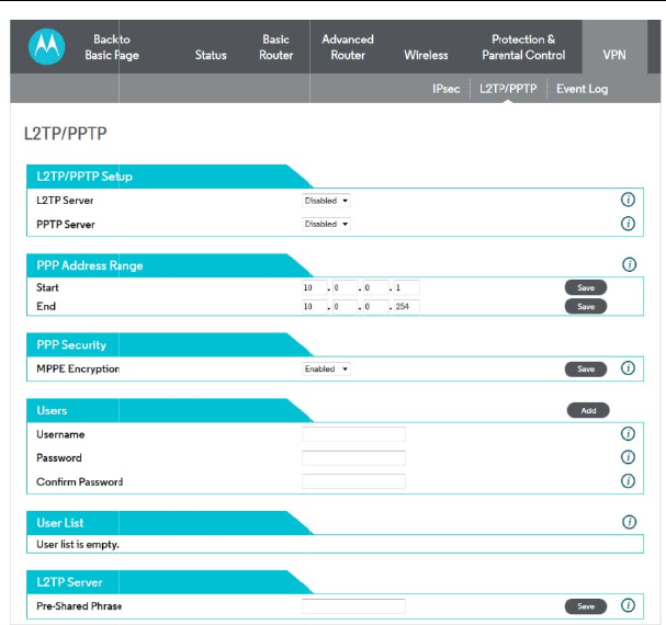
This page allo
w
5.6.3 Ev
Choose VPN >
MG7540 Cable
Figure 41 L2TP/PP
T
w
s configuration of L2TP
ent Lo
g
Event Log to display th
e
Modem User Manual
53
T
P configuration
and PPTP server option
s
e
following page.
s
.
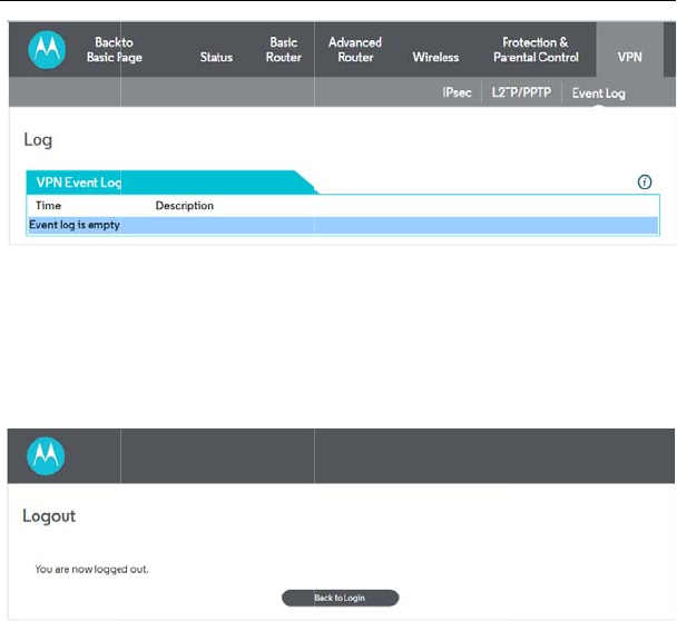
This page allo
w
5.7 Log
o
Choose Logo
u
MG7540 Cable
Figure 42 Event Log
w
s you to view the VPN
E
o
ut
u
t to logout Account and
t
Figure 43 The logou
t
Modem User Manual
54
information
E
vent Log.
t
he following page will b
e
t
page
e
shown after logout.

MG7540 Cable Modem User Manual
55
6 Q&A
(1) Q: Why all the indicators are off?
A: Check the following:
The connection between the power adaptor and the power socket.
The status of the power switch.
(2) Q: Why the Ethernet indicator is off?
A: Check the following:
The connection between the Cable Modem and your computer, hub,
or switch.
The running status of your PC, hub, or switch.
(3) Q: Why the ONLINE indicator is off?
A: Check CM DS/US LED is on. Check the connection between the Cable
Line and the wall HFC.
Apply customer :
Name: MTRLC LLC
Address: PO Box 121147 Boston, MA 02112-1147
Contact Person: Andy Pollock
Title: Director of Hardware Engineering
Telephone: 6177530663
Fax: 617-423-1075
For applicable power supplies :
1, US: S24B72-120A200-C4
Brand : Shenzhen Gongjin Electronics Co., Ltd
MG7540 Cable Modem User Manual
56
FCC statement
Warning: Changes or modifications to this unit not expressly approved by the
party responsible for compliance could void the user’s authority to operate the
equipment.
NOTE: This equipment has been tested and found to comply with the limits for
a Class B digital device, pursuant to Part 15 of the FCC Rules. These limits are
designed to provide reasonable protection against harmful interference in a
residential installation. This equipment generates, uses and can radiate radio
frequency energy and, if not installed and used in accordance with the
instructions, may cause harmful interference to radio communications.
However, there is no guarantee that interference will not occur in a particular
installation. If this equipment does cause harmful interference to radio or
television reception, which can be determined by turning the equipment off and
on, the user is encouraged to try to correct the interference by one or more of the
following measures:
Reorient or relocate the receiving antenna.
Increase the separation between the equipment and receiver.
Connect the equipment into an outlet on a circuit different from that to
which the receiver is connected.
Consult the dealer or an experienced radio/TV technician for help.
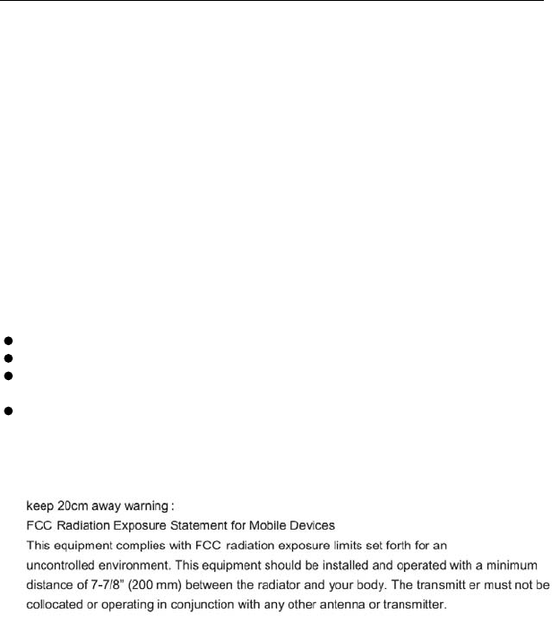
“FCC RF Radiation Exposure Statement Caution: To maintain
compliance with the FCC’s RF exposure guidelines, place the
product at least 20cm from nearby persons.”
“The device must not be co-located or operating in conjunction with any other antenna
or transmitter.”
5 GHz devices only
High power radars are allocated as primary users of the 5.25 to 5.35 GHz and 5.65
to 5.85 GHz bands. These radar stations can cause interference with and/or damage
this device. No configuration controls are provided for this wireless equipment allowing
any change in the frequency of operations outside the FCC grant of authorization for
US operation according to Part 15.407 of the FCC rules.