Mandolyn Electronic Technology WS Weather Station Receiver User Manual WS1233U manual UPM Rev1
Mandolyn Electronic Technology Inc. Weather Station Receiver WS1233U manual UPM Rev1
Contents
- 1. User Manual WS1233U
- 2. User Manual WS2211
- 3. User Manual WS2300U
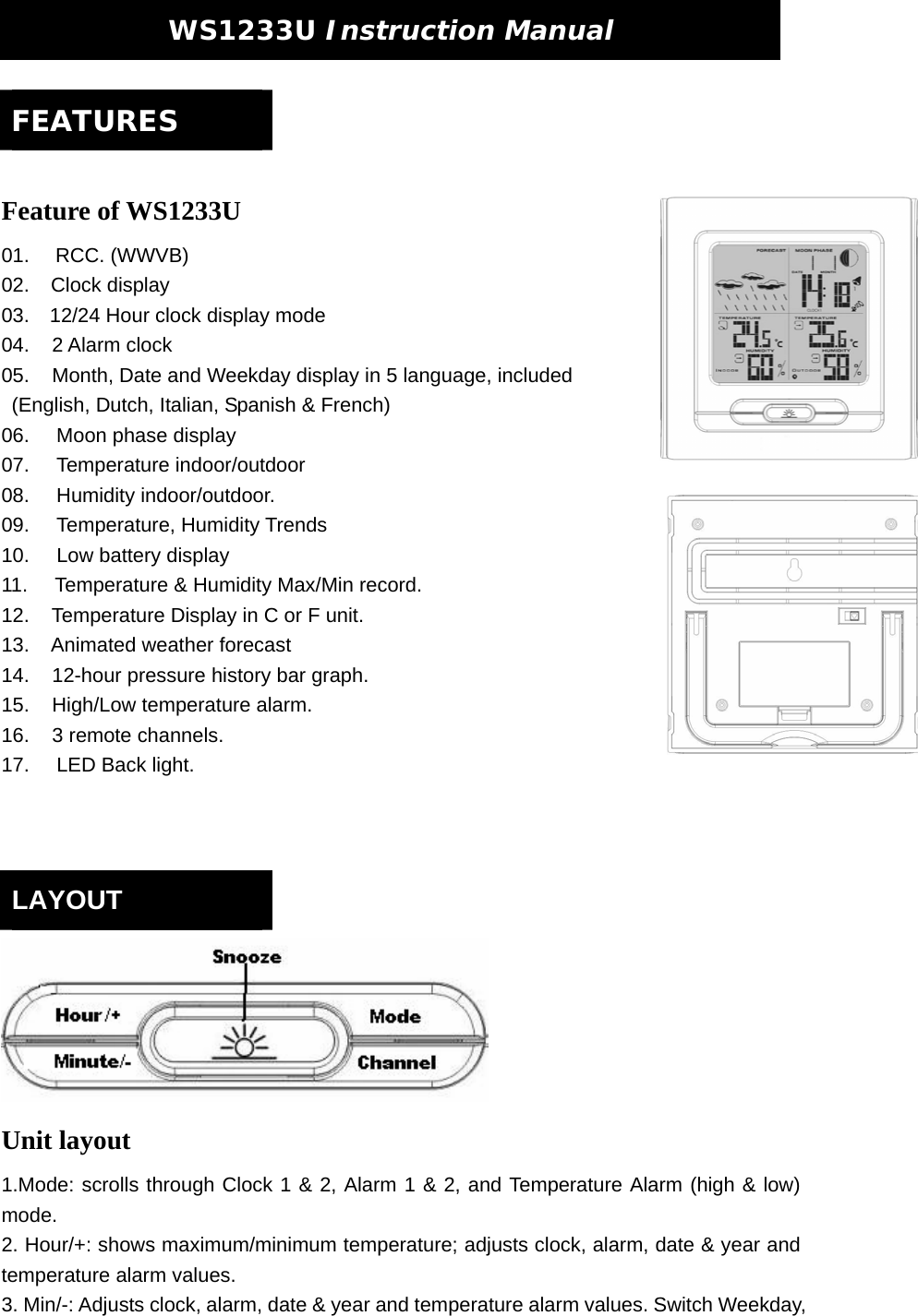
User Manual WS1233U
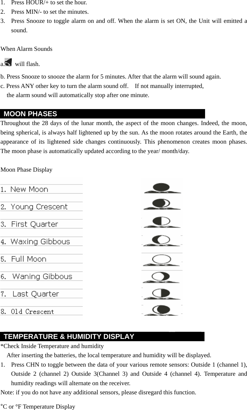
![temperature alarm or disable the alarm function (blank). 6. Press mode to save your settings. When the temperature alarm sounds The icon signals that the temperature has exceeded the preset temperature limit. a. Press any key to stop temperature alarm. b. If no key is pressed, the temperature alarm will automatically stop itself after one minute. c. Once triggered, temperature alarm comes on as a distinctive sound, different to that of Alarm1 and Alarm2. ] WEATHER FORECAST & DISPLAY Animated weather forecast symbols This weather station is capable of detecting barometric pressure changes, and based on the data collected, can predict the weather for the next 12 to 24 hours. The effective range covers an area of 30 – 50km. Sunny Cloudy Raining Snowing Freeze Warning Storm Alert Storm Alert The storm symbol will flash to warn of a thunderstorm. It is activated when pressure falls/rises and temperature plunges. About Snow and Freeze Warning The snow symbol will flash to warn that it might snow. Activated when the temperature of Channel 1 is between -1.9 °C & +2.9 °C.](https://usermanual.wiki/Mandolyn-Electronic-Technology/WS.User-Manual-WS1233U/User-Guide-839414-Page-7.png)
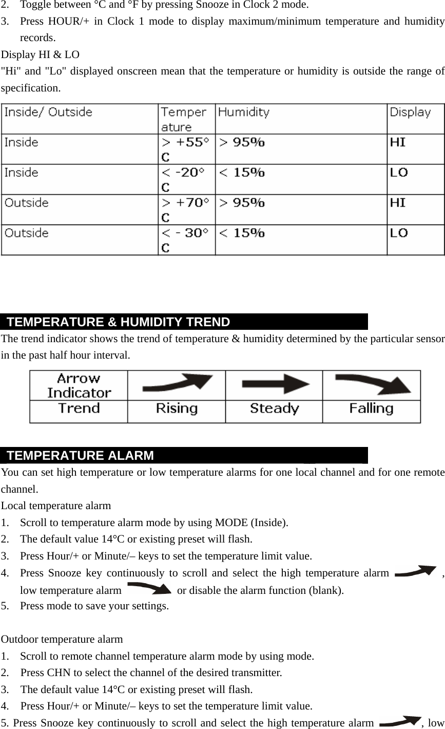
![The snow symbol will appear solid when the temperature of channel 1 falls below - 1.9 °C, and it is freezing. Note: The remote sensor set at channel 1 displays the weather forecast icons (as well as the trend indication). Please place it outdoors. REMARKS: After having completed the settings of your weather station, please discard the readings of the weather forecast for the next 12-24 hours. This will allow sufficient time for the Weather Station to operate at a constant altitude and therefore result in a more accurate forecast. Absolute accuracy cannot be guaranteed regarding weather forecasting. The weather forecasting feature is estimated to have an accuracy level of about 75% due to the varying areas the Weather Station has been designed to be used in. If the Weather Station is moved to another location significantly higher or lower than its initial standing point (e.g. from ground floor to 1st floor of a house), remove the batteries and reinsert them after about 30 seconds. By doing this, the Weather Station will mistakenly consider the new location as a possible change in air pressure. Again, discard the weather forecasts for the next 12-24 hours as to allow time for operation at a constant altitude. Specification Weather Station Receiver WS1233U Battery Type: 2 X1.5V AA batteries Temp.Range: -20 C to +55 C Measurement Accuracy: +/- 1.5 C Within measuring range of 0 to 0C Resolution: 0.1 C Humidity Range: 15% to 95% Measurement Accuracy: +/- 5% Resolution: 1% Trouble Shooting Problem: 1. The main unit cannot receive radio control WWVB signals to update the clock. 2. The temperature measurements of the remote sensor and receiver do not match. 3. Temperature reading of outdoor remote sensor seems too high. 4. Receiver is no longer receiving remote sensor signals or display. 5. An abnormal operation has been observed and certain functions do not work. Solution: 1. Place the clock away from metal objects or electrical appliances such as TVs, computers, monitors, etc. Trigger the scan manually by holding the Minute/- key [3] for 3 seconds. 2. Wait a few minutes to ensure the remote sensor and receiver are in phase. Otherwise, re-synchronize receiver by holding CHN for 3 seconds until a beep is heard. 3. Ensure the remote sensor is out of direct sunlight, and away from sources of heat.](https://usermanual.wiki/Mandolyn-Electronic-Technology/WS.User-Manual-WS1233U/User-Guide-839414-Page-8.png)
![ICES - 003 The statement required by ICES - 003 is as follows: NOTICE: This Class B digital apparatus complies with Canadian ICES-003. Cet appareil numérique de la classe [*] est conforme à la norme NMB-003 du Canada.](https://usermanual.wiki/Mandolyn-Electronic-Technology/WS.User-Manual-WS1233U/User-Guide-839414-Page-10.png)