Mandolyn Electronic Technology WS Weather Station Receiver User Manual WS1233U manual UPM Rev1
Mandolyn Electronic Technology Inc. Weather Station Receiver WS1233U manual UPM Rev1
Contents
- 1. User Manual WS1233U
- 2. User Manual WS2211
- 3. User Manual WS2300U
User Manual WS1233U
WS1233U Instruction Manual
FEATURES
Feature of WS1233U
01. RCC. (WWVB)
02. Clock display
03. 12/24 Hour clock display mode
04. 2 Alarm clock
05. Month, Date and Weekday display in 5 language, included
(English, Dutch, Italian, Spanish & French)
06. Moon phase display
07. Temperature indoor/outdoor
08. Humidity indoor/outdoor.
09. Temperature, Humidity Trends
10. Low battery display
11. Temperature & Humidity Max/Min record.
12. Temperature Display in C or F unit.
13. Animated weather forecast
14. 12-hour pressure history bar graph.
15. High/Low temperature alarm.
16. 3 remote channels.
17. LED Back light.
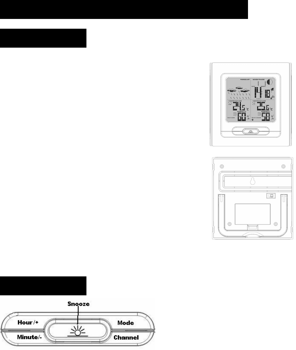
LAYOUT
Unit layout
1.Mode: scrolls through Clock 1 & 2, Alarm 1 & 2, and Temperature Alarm (high & low)
mode.
2. Hour/+: shows maximum/minimum temperature; adjusts clock, alarm, date & year and
temperature alarm values.
3. Min/-: Adjusts clock, alarm, date & year and temperature alarm values. Switch Weekday,
date/month and year display
4. Chn: scrolls through remote channels Outside 1, Outside 2 and outside 3); scrolls
through local and remote channels (Outside 1, Outside 2 and Outside 3) in (Max & Min)
temperature alarm mode; activates the learning procedure.
5. Snooze: Select Week/day language, toggles between 12 and 24 hour format, Alarm 1
& 2 On and Off; disables (resets) high & low temperature alarms; Alarm snooze. Select
C/F temperature display
6. Main LCD display with Green backlight.
7. House: enter House code.
8. Chn: Channel setting mode.
9. Battery compartment.
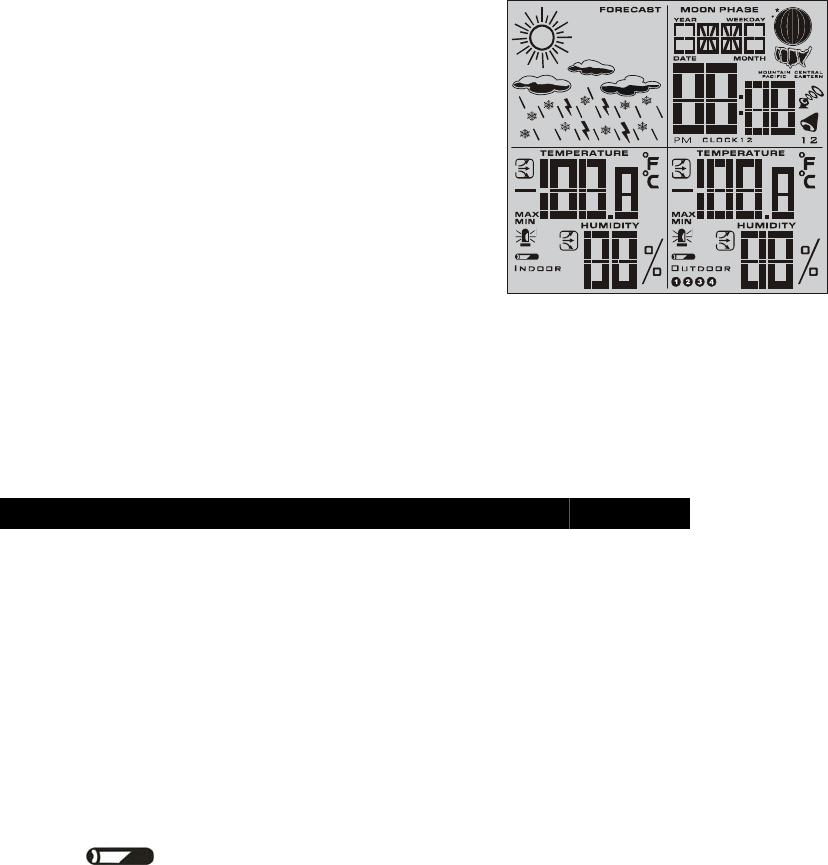
Display layout
1. Weather forecast symbol.
2. Moon phase display.
3. Weekday, date, month display.
4. Time display.
5. Alarm 1/2 icon.
6. RCC icon and zone map for USA.
7. Clock 1/2.
8. Outdoor temperature and trend.
9. Outdoor humidity and trend.
10. Remote channel 1,2,3 and 4.
11. Indoor temperature and trend.
12. Indoor humidity and trend.
POWER SUPPLY
Weather Station works with 2 AA batteries for the main unit and 2 AAA for the remote sensor (all
not included).
Battery installation
1. Main Unit: Use your finger to lift the battery door located at the back of the main unit. Insert
2 AA batteries according to the polarity. Close back the battery compartment.
2. Remote Sensor: Use a screwdriver to open the battery door located at the back of the remote
sensor unit. Insert 2 AA batteries according to the polarity. Close back the battery
compartment and tighten the screw.
LOW BATTERY INDICATION: If the batteries of the remote sensor are low, the following
indicator . will be displayed on the main unit. The indicator will also be displayed on the
bottom left corner of the remote sensor’s screen. When the main unit’s LCD display becomes dim,
it indicates that the batteries are low and need to be changed.

Note: if the sensor is exposed to very low temperatures for an extended period of time, the
batteries may lose power which may cause the transmission range to be limited. High
temperatures also reduce the battery performance.
GETTING STARTED
Setting the Main unit
1. Remove battery cover and insert 2xAA size batteries, ensure correct polarity + / - as shown in
the compartment, replace the cover.
SETUP
Automatic Learn Function:
Learn function executes automatically and runs for approximately 3 minutes when the batteries
are first installed in the receiver. Within these 3 minutes, the receiver picks up the temperature &
humidity signals from the remote sensor and displays the readings.
Manual-Learning (Searching for Remote Signals)
If a new remote sensor is added or if the signal is lost (outdoor display blinking), the learning
function must be executed again.
1. Press and hold CHN for 3 seconds to start.
2. A beep sound indicates that the learning function has started.
3. The 'Channel' symbol will flash and unit will beep as each remote sensor is detected.
4. Temperature & humidity readings of remote sensor are displayed on the receiver.
Fixing your sensor & receiver
The remote sensor has a wall mount holder. To fix it on a wall, fix the holder on a hook or nail.
The remote sensor should be fixed on a smooth surface to prevent altering the range of the date
transmission. To ensure a good transmission, the remote sensor should not install on or near a
large metal surface. Before choosing the location of the remote sensor, test that the receiver can
receive the signals. It is also recommended that the remote sensor is placed as close as possible to
the receiver to eliminate any interference. The receiver also has a wall mount holder and a stand.
To place it, use the same precautions as for the remote sensor.
Backlight:
The default state of the Backlight is Off. To turn the backlight on, press any button. It will stay on
for about 10 seconds.
CLOCK AND DATE SETTINGS
RADIO CONTROL CLOCK (WWVB---TBA)
- The WS1233 is designed to automatically synchronize its calendar clock once it is brought
within the reception range of a radio signal.
1. The clock automatically starts scanning the RF 433MHz signal after new batteries are inserted
in the main unit. When receiving radio signal, the Radio Tower symbol starts to blink. A complete
reception generally takes several minutes, depending on the strength of the radio signal. The scan
can also be triggered manually by holding the Min/- key for 3 seconds.
2. When the reception is complete, the Radio Tower symbol will stop blinking and remain solid.

The clock automatically scans the time signal at 02:07 everyday to maintain accurate timing.
Notes:
• For an optimal reception, place the clock away from metal objects and electrical appliances (i.e.
television, computer, monitor, etc.) to minimize interference.
• If the user sets the time (year/month/date/hour/minute) manually, the unit will stop receiving the
radio control clock signals.
Clock 1 setting
1. Press Snooze key on Clock 1 mode to alternative between the 12 and 24 hour display.
2. Press and hold mode for 3 seconds to enter the clock setting mode (the CLOCK 1 symbol will
appear, and the time will flash).
3. Press Hour/+ to set the hour and Minute/- to set the minutes.
4. Press Snooze during the clock settings to select the language of week/day display.
Note:
• If you do not press any key for one minute, the clock will accept the last settings entered.
• February will have either 28 or 29 days. Your weather station will display the 29th day on
bissextile years.
DATE/MONTH/YEAR SETTING
1. After clock 1 is set, press Mode to accept the time settings. Upon pressing mode, the month
and date will flash.
2. Press the Hour/+ to set the month.
3. Press the Minute/- to set the date.
4. Press Mode, the year will flash. Press the Hour/+ to move the year upwards and Minute/- to
move the year downwards. Press Mode to confirm all your settings.
Clock 2 Settings (Dual Time)
1. Scroll to Clock 2 using Mode.
2. Press + or – key to change the hour (in hour increments/decrements relative to Clock 1).
Other settings of clock display
1. Press "Hour/+" on clock 1 mode shows maximum/minimum temperature, press "Hour/+"
for 3 seconds resets maximum/minimum temperature record.
2. Press "Minute/-" on clock 1 mode switches the weekday/Date month/Year display.
3. Press "Snooze" on clock 1 mode to switch the 12/24 hour time format.
4. Press "Snooze" on clock 2 mode switches the C/F display.
ALARM SETTING
Alarm Setting
Scroll to Alarm1 mode (Alarm2 mode) using MODE
1. Press HOUR/+ to set the hour.
2. Press MIN/- to set the minutes.
3. Press Snooze to toggle alarm on and off. When the alarm is set ON, the Unit will emitted a
sound.
When Alarm Sounds
a. will flash.
b. Press Snooze to snooze the alarm for 5 minutes. After that the alarm will sound again.
c. Press ANY other key to turn the alarm sound off. If not manually interrupted,
the alarm sound will automatically stop after one minute.
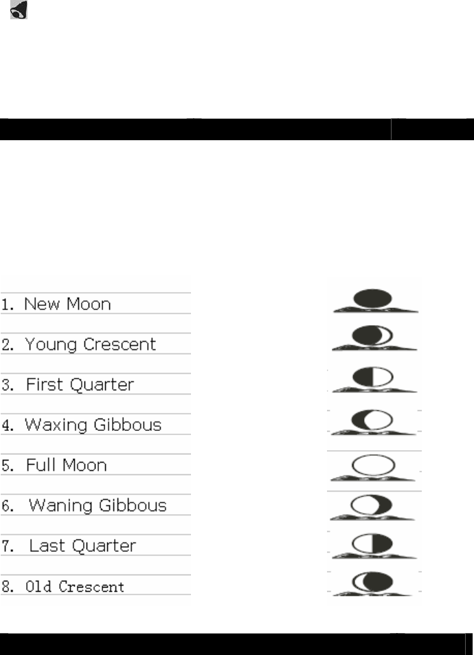
MOON PHASES
Throughout the 28 days of the lunar month, the aspect of the moon changes. Indeed, the moon,
being spherical, is always half lightened up by the sun. As the moon rotates around the Earth, the
appearance of its lightened side changes continuously. This phenomenon creates moon phases.
The moon phase is automatically updated according to the year/ month/day.
Moon Phase Display
TEMPERATURE & HUMIDITY DISPLAY
*Check Inside Temperature and humidity
After inserting the batteries, the local temperature and humidity will be displayed.
1. Press CHN to toggle between the data of your various remote sensors: Outside 1 (channel 1),
Outside 2 (channel 2) Outside 3(Channel 3) and Outside 4 (channel 4). Temperature and
humidity readings will alternate on the receiver.
Note: if you do not have any additional sensors, please disregard this function.
°C or °F Temperature Display
2. Toggle between °C and °F by pressing Snooze in Clock 2 mode.
3. Press HOUR/+ in Clock 1 mode to display maximum/minimum temperature and humidity
records.
Display HI & LO
"Hi" and "Lo" displayed onscreen mean that the temperature or humidity is outside the range of
specification.
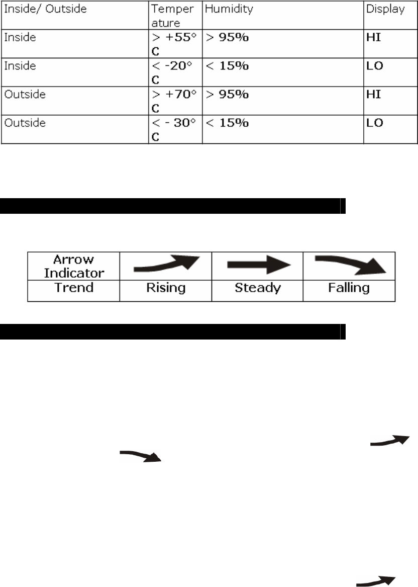
TEMPERATURE & HUMIDITY TREND
The trend indicator shows the trend of temperature & humidity determined by the particular sensor
in the past half hour interval.
TEMPERATURE ALARM
You can set high temperature or low temperature alarms for one local channel and for one remote
channel.
Local temperature alarm
1. Scroll to temperature alarm mode by using MODE (Inside).
2. The default value 14°C or existing preset will flash.
3. Press Hour/+ or Minute/– keys to set the temperature limit value.
4. Press Snooze key continuously to scroll and select the high temperature alarm ,
low temperature alarm or disable the alarm function (blank).
5. Press mode to save your settings.
Outdoor temperature alarm
1. Scroll to remote channel temperature alarm mode by using mode.
2. Press CHN to select the channel of the desired transmitter.
3. The default value 14°C or existing preset will flash.
4. Press Hour/+ or Minute/– keys to set the temperature limit value.
5. Press Snooze key continuously to scroll and select the high temperature alarm , low
temperature alarm or disable the alarm function (blank).
6. Press mode to save your settings.
When the temperature alarm sounds
The icon signals that the temperature has exceeded the preset temperature limit.
a. Press any key to stop temperature alarm.
b. If no key is pressed, the temperature alarm will automatically stop itself after one minute.
c. Once triggered, temperature alarm comes on as a distinctive sound, different to that of Alarm1
and Alarm2.
]
WEATHER FORECAST & DISPLAY
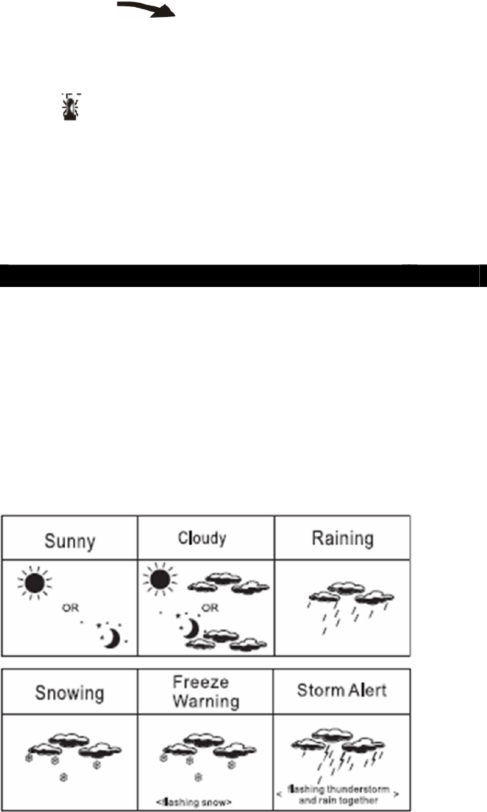
Animated weather forecast symbols
This weather station is capable of detecting barometric pressure changes, and based on the data
collected, can predict the weather
for the next 12 to 24 hours. The effective range covers an area of 30 – 50km.
Sunny
Cloudy
Raining
Snowing
Freeze Warning
Storm Alert
Storm Alert
The storm symbol will flash to warn of a thunderstorm.
It is activated when pressure falls/rises and temperature plunges.
About Snow and Freeze Warning
The snow symbol will flash to warn that it might snow.
Activated when the temperature of Channel 1 is between -1.9 °C & +2.9 °C.
The snow symbol will appear solid when the temperature of channel 1 falls below - 1.9 °C, and it
is freezing.
Note:
The remote sensor set at channel 1 displays the weather forecast icons (as well as the trend
indication). Please place it outdoors.
REMARKS:
After having completed the settings of your weather station, please discard the readings of the
weather forecast for the next 12-24 hours. This will allow sufficient time for the Weather Station
to operate at a constant altitude and therefore result in a more accurate forecast. Absolute accuracy
cannot be guaranteed regarding weather forecasting. The weather forecasting feature is estimated
to have an accuracy level of about 75% due to the varying areas the Weather Station has been
designed to be used in. If the Weather Station is moved to another location significantly higher or
lower than its initial standing point (e.g. from ground floor to 1st floor of a house), remove the
batteries and reinsert them after about 30 seconds. By doing this, the Weather Station will
mistakenly consider the new location as a possible change in air pressure. Again, discard the
weather forecasts for the next 12-24 hours as to allow time for operation at a constant altitude.
Specification
Weather Station Receiver WS1233U
Battery Type: 2 X1.5V AA batteries
Temp.Range: -20 C to +55 C
Measurement Accuracy: +/- 1.5 C Within measuring range of 0 to 0C
Resolution: 0.1 C
Humidity Range: 15% to 95%
Measurement Accuracy: +/- 5%
Resolution: 1%
Trouble Shooting
Problem:
1. The main unit cannot receive radio control WWVB signals to update the clock.
2. The temperature measurements of the remote sensor and receiver do not match.
3. Temperature reading of outdoor remote sensor seems too high.
4. Receiver is no longer receiving remote sensor signals or display.
5. An abnormal operation has been observed and certain functions do not work.
Solution:
1. Place the clock away from metal objects or electrical appliances such as TVs,
computers, monitors, etc.
Trigger the scan manually by holding the Minute/- key [3] for 3 seconds.
2. Wait a few minutes to ensure the remote sensor and receiver are in phase. Otherwise,
re-synchronize
receiver by holding CHN for 3 seconds until a beep is heard.
3. Ensure the remote sensor is out of direct sunlight, and away from sources of heat.

4. Repeat the learning procedures.
- Temperature may be below -30°C.
- Batteries in remote sensor may need changing.
- Move remote sensor closer to the receiver.
- Make sure remote sensor is away from sources of electrical disturbance.
5. Reset the unit by replacing the batteries in both the transmitters and receiver.
FCC Statement
The statement required by 15.105 is as follows:
This equipment has been tested and found to comply with the limits for a Class B digital
device, pursuant to Part 15 of the FCC Rules. These limits are designed to provide
reasonable protection against harmful interference in a residential installation. This
equipment generates, uses and can radiate radio frequency energy and, if not installed and
used in accordance with the instructions, may cause harmful interference to radio
communications. However, there is no guarantee that interference will not occur in a
particular installation. If this equipment does cause harmful interference to radio or
television reception, which can be determined by turning the equipment off and on, the user is
encouraged to try to correct the interference by one or more of the following measures:
- Reorient or relocate the receiving antenna.
- Increase the separation between the equipment and receiver.
- Connect the equipment into an outlet on a circuit different from that to which the receiver is
connected.
- Consult the dealer or an experienced radio/TV technician for help.
Statement required by 15.19 and RSS210
This device complies with Part 15 of the FCC Rules and with RSS-210 of Industry
Canada.
Operation is subject to the following two conditions:
(1) this device may not cause harmful interference, and
(2) this device must accept any interference received, including interference
that may cause undesired operation.
Manual Requirements according 15.21
NOTICE:
Changes or modifications made to this equipment not expressly approved by UPM
may void the FCC authorization to operate this equipment.

ICES - 003
The statement required by ICES - 003 is as follows:
NOTICE:
This Class B digital apparatus complies with Canadian ICES-003.
Cet appareil numérique de la classe [*] est conforme à la norme NMB-003 du
Canada.