Marelli ASTU13 Automotove Keyless Entry System Transmitter User Manual MEASUREMENT TECHNICAL REPORT
Calsonic Kansei Corporation Automotove Keyless Entry System Transmitter MEASUREMENT TECHNICAL REPORT
Marelli >
Contents
- 1. Manual
- 2. Test Report more
Test Report more
Testing Laboratory
A-pex International Co., Ltd. Telephone: +81 596 39 1485
108 Yokowa-cho, Ise-shi Mie-ken 516-1106 JAPAN Facsimile: +81 596 39 0232
EMISSION TEST REPORT
Test Report No. : 21BE0029YW-1
Applicant: CALSONIC KANSEI CORP.
Type of Equipment: Keyless Entry System (Transmitter)
Model No.: ASTU13
Test standard: FCC Part 15 Subpart C
Test Result: Complies
This report may not be reproduced in full, partial reproduction may only be made with the
written consent of the laboratory.
The results in this report apply only to the sample tested.
Date of test: September 14, 2000
Tested by:
Naoki Sakamoto
Approved by:
Issued date: October 5, 2000
Kazutoyo Nakanishi
Section Manager of EMC section

Test report
Our reference : 21BE0029YW-1
Page : 2of 12
Issued date : October 5, 2000
FCC ID : KBRASTU13
Testing Laboratory
A-pex International Co., Ltd. Telephone: +81 596 39 1485
108 Yokowa-cho, Ise-shi Mie-ken 516-1106 JAPAN Facsimile: +81 596 39 0232
Table of Contents Page
1 GENERAL INFORMATION 3
1.1 Product Description 4
1.2 Tested System Details 4
1.3 Tested Methodology 4
1.4 Test Facility 4
2 SYSTEM TEST CONFIGURATION 5
2.1 Operation Environment 5
2.2 Justification 5
2.3 EUT Exercise Software 5
2.4 Test Procedure 5
Figure 2.1 Configuration of Tested System 6
3 RADIATED MEASUREMENT PHOTOS 7
Figure 3.1 Radiated Measurement Photos 7
3.1 Measurement Uncertainty 8
4 RADIATED EMISSION DATA 9
4.1 Field Strength Calculation 9
5 TEST EQUIPMENT USED 11
APPENDIX 12
A:Test Data A1 – A3

Test report
Our reference : 21BE0029YW-1
Page : 3of 12
Issued date : October 5, 2000
FCC ID : KBRASTU13
Testing Laboratory
A-pex International Co., Ltd. Telephone: +81 596 39 1485
108 Yokowa-cho, Ise-shi Mie-ken 516-1106 JAPAN Facsimile: +81 596 39 0232
1 GENERAL INFORMATION
APPLICANT : CALSONIC KANSEI CORP.
TRADE NAME : CALSONIC KANSEI
ADDRESS : 5-24-15 Minamidai, Nakano-ku, Tokyo
164-8602 Japan
Tel: +81-283-21-8136
Fax: +81-283-23-9191
REGULATION(S) : FCC Part 15 Subpart C
MODEL NUMBER : ASTU13
FCC ID : KBRASTU13
SERIAL NUMBER : -
KIND OF EQUIPMENT : Keyless Entry System (Transmitter)
TESTED DATE : September 14, 2000
RECEIPT DATE OF SAMPLE : September 14, 2000
REPORT FILE NUMBER : 21BE0029YW-1
TEST SITE : A-PEX Yokowa NO.3 Open Test Site

Test report
Our reference : 21BE0029YW-1
Page : 4of 12
Issued date : October 5, 2000
FCC ID : KBRASTU13
Testing Laboratory
A-pex International Co., Ltd. Telephone: +81 596 39 1485
108 Yokowa-cho, Ise-shi Mie-ken 516-1106 JAPAN Facsimile: +81 596 39 0232
1.1 Product Description
Model: ASTU13 (referred to as the EUT in this report) is a Keyless Entry System (Transmitter).
.
The specification is as following :
Operation Frequency : 4 MHz
Carrier Frequency : 315 MHz
Operation Voltage : DC 3.2V
1.2 Tested Equipment Details
Model FCC ID Description Cable description Backshell Material
(1) CALSONIC KANSEI KBRASTU13 Keyless Entry System - - - P.V.C
M/N: ASTU13 (Transmitter)
(EUT)
1.3 Tested Methodology
Radiated testing were performed according to the procedures in FCC/ANSI C63.4 (1992).
1.4 Test Facility
The open area test site and conducted measurement facility used to collect the radiated data is located on
108 Yokowa-cho, Ise-shi, Mie-ken 516-1106 Japan.
This site has been fully described in a report submitted to FCC office, and listed on September 12, 2000
(Registration number: 90412).

Test report
Our reference : 21BE0029YW-1
Page : 5of 12
Issued date : October 5, 2000
FCC ID : KBRASTU13
Testing Laboratory
A-pex International Co., Ltd. Telephone: +81 596 39 1485
108 Yokowa-cho, Ise-shi Mie-ken 516-1106 JAPAN Facsimile: +81 596 39 0232
2 SYSTEM TEST CONFIGURATION
2.1 Operation Environment
Temperature : 23℃
Humidity : 60%
Power supply : DC 3.2V
2.2 Justification
The system was configured in typical fashion (as a customer would normally use it) for testing.
2.3 EUT Exercise Software
The EUT exercise program used during radiated testing was designed to exercise
the various system components in a manner similar to typical use.
The sequence is used:
Operation Mode : Transmitting
2.4 Test Procedure
Tabletop Equipment Radiated Emissions
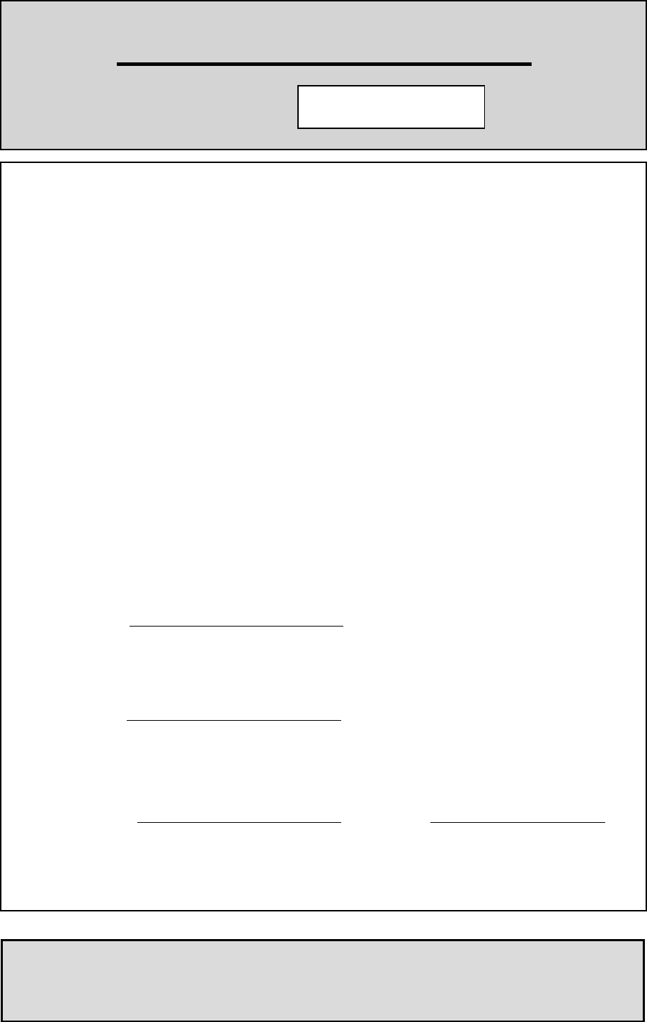
EUT was placed on a platform of nominal size, 1m by 1.5m, raised 80cm above the conducting ground plane.
Test was made with the antenna positioned in both the horizontal and vertical planes of polarization.
The measurement antenna was varied in height above the conducting ground plane to obtain the maximum signal strength.
The measurement distance was 3m.
Test report
Our reference : 21BE0029YW-1
Page : 6of 12
Issued date : October 5, 2000
FCC ID : KBRASTU13
Testing Laboratory
A-pex International Co., Ltd. Telephone: +81 596 39 1485
108 Yokowa-cho, Ise-shi Mie-ken 516-1106 JAPAN Facsimile: +81 596 39 0232
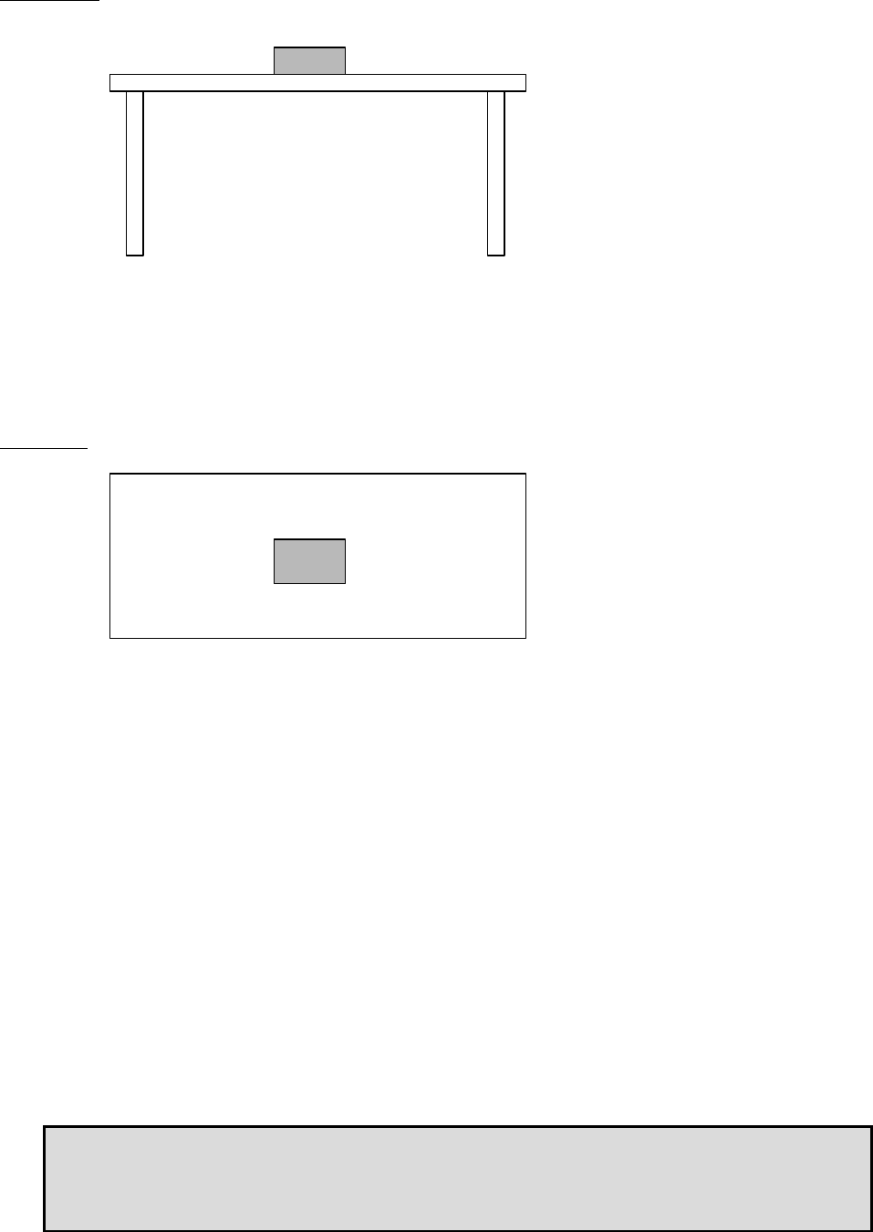
Figure2.1 Configuration of Tested System
Front View
(1):EUT
* Test data was taken under worse case conditions.
Top View
(1):EUT
* Test data was taken under worse case conditions.

Test report
Our reference : 21BE0029YW-1
Page : 7of 12
Issued date : October 5, 2000
FCC ID : KBRASTU13
Testing Laboratory
A-pex International Co., Ltd. Telephone: +81 596 39 1485
108 Yokowa-cho, Ise-shi Mie-ken 516-1106 JAPAN Facsimile: +81 596 39 0232
3 RADIATED MEASUREMENT PHOTOS
Figure 3.1 Radiated Measurement Photos

Test report
Our reference : 21BE0029YW-1
Page : 8of 12
Issued date : October 5, 2000
FCC ID : KBRASTU13
Testing Laboratory
A-pex International Co., Ltd. Telephone: +81 596 39 1485
108 Yokowa-cho, Ise-shi Mie-ken 516-1106 JAPAN Facsimile: +81 596 39 0232
3.1 Measurement Uncertainty
Radiated Emission Test
The measurement uncertainty (with a 95% confidence level) for this test was ±3.3dB.
■ The data listed in this test report may exceed the test limit because it does not have enough margin (more than 3.3dB).
□ The data listed in this test report has enough margin, more than 3.3dB.

Test report
Our reference : 21BE0029YW-1
Page : 9of 12
Issued date : October 5, 2000
FCC ID : KBRASTU13
Testing Laboratory
A-pex International Co., Ltd. Telephone: +81 596 39 1485
108 Yokowa-cho, Ise-shi Mie-ken 516-1106 JAPAN Facsimile: +81 596 39 0232
4 RADIATED EMISSION DATA
The initial step in collecting radiated data was a spectrum analyzer peak scan of the measurement range (30MHz-3300MHz).
The final data was reported in the worst-case emissions.
The minimum margin to the limit is as follows :
Receiver Correction Field
Frequency Reading Factor Strength Limit Margin
(MHz) (dBμV) (dBμV) (dBμV/m) (dBμV/m) (dBμV)
315.00 78.2 -3.8 74.4 75.6 1.2
* quasi-peak mode
The Fundamental Frequency of this equipment is 315MHz. The peak of output level of fundamental frequency was
confirmed at the 315MHz by perfarming the meaurement.
It was corroborated that equipment was within of the tolerance which is prescribed
in the FCC requlation Part 15 Subpart C sec. 15.231 (c).
Since the fundamental frequency is 315MHz, the upper limit could be 315.8 MHz and lower limit could be 314.2MHz.
The measurement result was 315.2MHz when the limit was 315.8MHz and also another measurement result was 314.8 MHz
when the limit was 314.2MHz.

Test report
Our reference : 21BE0029YW-1
Page : 10of 12
Issued date : October 5, 2000
FCC ID : KBRASTU13
Testing Laboratory
A-pex International Co., Ltd. Telephone: +81 596 39 1485
108 Yokowa-cho, Ise-shi Mie-ken 516-1106 JAPAN Facsimile: +81 596 39 0232
5.1 Field Strength Calculation
The field strength is calculated by adding the Antenna Factor, Cable Factor and Antenna Pad, and subtracting the Amplifier
Gain from the measured reading. The sample calculation is as follows :
FS = RA + AF + CF + AT - AG
where FS = Field Strength
RA = Receiver Amplitude
AF = Antenna Factor
CF = Cable Factor
AT = Antenna Pad
AG = Amplifier Gain
Assume a receiver reading of 78.2 dBμV is obtained. The antenna Factor of 14.0 dB, Cable Factor of 4.5 dB and Antenna
Pad of 6.0 dB is added. The Amplifier Gain of 28.3 dB is subtracted, giving a field strength of 74.4 dBμV/m.
FS = 78.2 + 14.0 + 4.5 + 6.0 – 28.3 = 74.4 dBμV/m

Test report
Our reference : 21BE0029YW-1
Page : 11of 12
Issued date : October 5, 2000
FCC ID : KBRASTU13
Testing Laboratory
A-pex International Co., Ltd. Telephone: +81 596 39 1485
108 Yokowa-cho, Ise-shi Mie-ken 516-1106 JAPAN Facsimile: +81 596 39 0232
6 TEST EQUIPMENT USED
INSTRUMENTS Mfr. MODEL C/N Calibrated Until
■ Pre Amplifier Hewlett Packard 8447D AF1 November 16, 2000
□ Pre Amplifier Anritsu MH648A AF3 November 16, 2000
■ Pre Amplifier Hewlett Packard 8449B AF4 November 16, 2000
□ Attenuator Anritsu MP721B AT6 June 8, 2001
□ Biconical Antenna Schwarzbeck BBA9106 BA1 April 28, 2001
□ Biconical Antenna Schwarzbeck BBA9106 BA3 April 28, 2001
■ Biconical Antenna Schwarzbeck BBA9106 BA5 April 28, 2001
■ Horn Antenna A.H. Systems SAS200/571 HA1 February 4, 2001
■ Logperiodic Antenna Schwarzbeck UHAP9108-A LA6 April 29, 2001
□ Logperiodic Antenna Schwarzbeck UKLP9140-A LA8 April 29,
2001
□ Loop Antenna Rohde & Schwarz HFH2-Z2 LP1 November 3, 2000
□ LISN Rohde & Schwarz ESH2-Z5 LS1 November 15, 2000
□ LISN Rohde & Schwarz ESH3-Z5 LS2 November 15, 2000
□ LISN Schwarzbeck NSLK8127 LS3 November 15, 2000
□ LISN Rohde & Schwarz ESH3-Z5 LS4 November 15, 2000
□ LISN Schwarzbeck NNLK8121 LS5 November 15, 2000
□ LISN Rolf Heine NNB-4/200 LS6 November 15, 2000
□ LISN Schwarzbeck NNLK8126 LS7 November 15, 2000
□ LISN Schwarzbeck NSLK8127 LS10 April 8, 2001
□ Spectrum Analyzer Hewlett Packard 8567A SA3 December 13, 2000
■ Spectrum Analyzer Hewlett Packard 8567A SA4 December 13, 2000
■ Spectrum Analyzer Advantest R3271 SA5 September 27, 2000
□ Test Receiver Rohde & Schwarz ESHS-20 TR1 March 30, 2001
■ Test Receiver Rohde & Schwarz ESVS-30 TR2 July 13, 2001
□ Test Receiver Rohde & Schwarz ESCS30 KTR1 August 7, 2001
■ indicates EMI Test Equipment used.
*All measurement equipment is traceable to national standard.

Test report
Our reference : 21BE0029YW-1
Page : 12of 12
Issued date : October 5, 2000
FCC ID : KBRASTU13
Testing Laboratory
A-pex International Co., Ltd. Telephone: +81 596 39 1485
108 Yokowa-cho, Ise-shi Mie-ken 516-1106 JAPAN Facsimile: +81 596 39 0232
APPENDIX
A : Test Data
Radiated emissions A1 – A3