manual

MANUFACTURER: MARPOSS S.p.A.
ADDRESS:Via Saliceto, 13 - Bentivoglio (BO) - Italy
CODE OF MANUAL:________________________________________________
ISSUE:________________________________________________
DEPT:________________________________________________
D31014BM11
01.02
M.U. MIDA
TOUCH SYSTEM WITH RADIO TRANSMISSION
(USA AND CANADA VERSION)
OPERATING INSTRUCTIONS
SISTEMA TOUCH CON TRASMISSIONE RADIO
(VERSIONE USA E CANADA)
ISTRUZIONI PER L'INSTALLAZIONE E L'USO
SCHALTSYSTEM MIT FUNK-ÜBERTRAGUNG
(USA UND CANADA VERSION)
INSTALLATIONS- UND BEDIENUNGSANLEITUNG
DETECTEUR TOUCH A TRANSMISSION RADIO
(VERSION POUR LES ÉTATS UNIS ET LE CANADA)
INSTRUCTIONS D'INSTALLATION ET D'ENTRETIEN


MARPOSS S.p.A. does not take on the obligation of notifying possible further changes to the
product.
The descriptions reported in this book not authorize any tampering by non-authorized personnel.
The warranty on the equipments will decay if such tamperings are found.
MARPOSS S.p.A. non assume l'obbligo di notificare eventuali successive modifiche al prodotto.
Le descrizioni riportate nel presente libro non autorizzano in alcun modo manomissioni da parte di
personale non autorizzato.
La garanzia sulle apparecchiature decade nel momento in cui tali manomissioni vengano riscon-
trate.
MARPOSS S.p.A. ist nicht verpflichtet, nachträgliche Produktänderungen mitzuteilen.
Die in diesem Handbuch enthaltenen Beschreibungen rechtfertigen keine Eingriffe durch nicht dazu
ermächtiges Personal.
Bei Feststellung derartiger Eingriffe verfällt der Garantieanspruch.
La Société MARPOSS S.p.A. n'est pas tenue de notifier les éventuelles modifications qu'elle pourra
apporter au produit.
Les descriptions figurant dans le présent livret n'autorisent en aucune façon des interventions du
personnel non autorisé.
La garantie sur les appareils ne s'appliquera pas si sont constatées des interventions de ce genre.
© Copyright Marposs 2002
THIS EQUIPMENT HAS BEEN TESTED AND FOUND TO COMPLY WITH THE LIMITS FOR A CLASS B DIGITAL DEVICE,
PURSUANT TO PART 15 OF THE FCC RULES. THESE LIMITS ARE DESIGNED TO PROVIDE REASONABLE PROTECTION
AGAINST HARMFUL INTERFERENCE IN A RESIDENTIAL INSTALLATION. THIS EQUIPMENT GENERATES, USES AND CAN
RADIATE RADIO FREQUENCY ENERGY AND, IF NOT INSTALLED AND USED IN ACCORDANCE WITH THE INSTRUCTIONS,
MAY CAUSE HARMFUL INTERFERENCE TO RADIO COMMUNICATIONS. HOWEVER, THERE IS NO GUARANTEE THAT
INTERFERENCE WILL NOT OCCUR IN A PARTICULAR INSTALLATION. IF THIS EQUIPMENT DOES CAUSE HARMFUL
INTERFERENCE TO RADIO OR TELEVISION RECEPTION, WHICH CAN BE DETERMINED BY TURNING THE EQUIPMENT OFF
AND ON, THE USER IS ENCOURAGED TO TRY TO CORRECT THE INTERFERENCE BY ONE OR MORE OF THE FOLLOWING
MEASURES:
·REORIENT OR RELOCATE THE RECEIVING ANTENNA
·INCREASE THE SEPARATION BETWEEN THE EQUIPMENT AND THE RECEIVER.
·CONNECT THE EQUIPMENT INTO AN OUTLET ON A CIRCUIT DIFFERENT FROM THAT TO WHICH THE RE
CEIVER IS CONNECTED.
·CONSULT THE DEALER OR AN EXPERIENCED RADIO/TV TECHNICIAN FOR HELP.
CHANGES OR MODIFICATIONS NOT EXPRESSLY APPROVED IN WRITING BY THE MANUFACTURER MAY VOID THE
USER´S AUTHORITY TO OPERATE THIS EQUIPMENT.
THIS DEVICE COMPLIES WITH PART 15 OF THE FCC RULES. OPERATION IS SUBJECT TO THE FOLLOWING TWO
CONDITIONS: (1) THIS DEVICE MAY NOT CAUSE HARMFUL INTERFERENCE, AND (2) THIS DEVICE MUST ACCEPT ANY
INTERFERENCE RECEIVED, INCLUDING INTERFERENCE THAT MAY CAUSE UNDESIRED OPERATION.
INDEX
1 SPECIFICATIONS AND GENERAL WARNINGS
PG
.
1.1 Specifications and general warnings.................. 6
2 SYSTEM COMPONENTS
PG
.
2.1 System components ......................................... 10
3 SYSTEM COMPONENTS
PG
.
3.1 System components ......................................... 12
4 SYSTEM OPERATION
PG
.
4.1 System operation .............................................. 14
5 MEASUREMENT PROBE
PG
.
5.1 Measurement probe .......................................... 16
6 RADIO TRANSMISSION
PG
.
6.1 Description ........................................................ 18
6.2 Transmission activation .................................... 20
6.2.1 Radio starting ......................................... 20
6.2.2 Mechanical starting ................................ 20
6.3 Stopping transmission ...................................... 22
7 E86 TRANSMITTER
PG
.
7.1 Description ........................................................ 24
7.2 Battery life ......................................................... 26
7.3 Programming the transmitter ............................ 28
7.4 Transmitter dimensions with probe .................. 34
8 E86 RECEIVER
PG
.
8.1 Description ........................................................ 36
8.2 Connecting up the antenna .............................. 38
8.3 Fitting the antenna to the machine ................... 40
8.4 Antenna dimensions ......................................... 41
9 E86 INTERFACE UNIT
PG
.
9.1 Interface unit front panel ................................... 42
9.2 Interface unit dimensions ................................. 43
9.3 E86 Interface unit technical features................ 44
9.4 Programming the interface unit ........................ 46
9.5 Connecting up the interface unit ...................... 52
10 ASSEMBLING THE
PROBE TO THE TRANSMITTER
PG
.
10.1 Assembling the probe to the transmitter .......... 60
11 INSERTING PROBE EXTENSIONS (OPTIONAL)
PG
.
11.1 Inserting probe extensions (optional) ............... 62
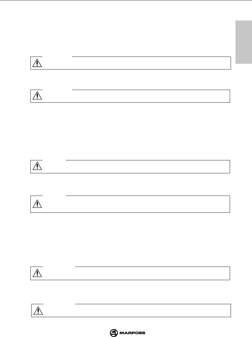
12 FITTING THE TRANSMITTER TO THE TAPER
PG
.
12.1 Fixing the transmitter ........................................ 66
12.2 Fixing the transmitter with the adjusting plate 68
13 FITTING THE PROBE STYLUS
PG
.
13.1 Fitting the probe stylus ..................................... 74
14 DIAGNOSTICS
PG
.
14.1 Fault finding guide............................................. 76
15 MAINTENANCE
PG
.
15.1 Ordinary maintenance ...................................... 80
15.1.1 Cleaning and inspection ........................ 80
15.1.2 Fitting/changing the battery ................... 82
15.2 Extraordinary maintenance ............................... 84
15.2.1 Changing the break pin and the stylus . 84
15.2.2 Replacement of outer seal .................... 86
15.2.3 Changing the probe from the transmitter 87
16 SPARE PART LIST
PG
.
16.1 Spare part list .................................................... 88

INDICE
1 NORME ED AVVERTENZE GENERALI
PAG
.
1.1 Norme ed avvertenze generali ............................. 7
2 COMPONENTI DEL SISTEMA
PAG
.
2.1 Componenti del sistema .................................... 11
3 CONFIGURAZIONE E FUNZIONAMENTO
PAG
.
3.1 Configurazione e funzionamento ....................... 13
4 MODALITÀ DI IMPIEGO
PAG
.
4.1 Modalità di impiego ........................................... 15
5 SONDA DI MISURA
PAG
.
5.1 Sonda di misura ................................................. 16
6 TRASMISSIONE RADIO
PAG
.
6.1 Descrizione ........................................................ 19
6.2 Attivazione della trasmissione ........................... 21
6.2.1 Attivazione radio .................................... 21
6.2.2 Attivazione meccanica ........................... 21
6.3 Disattivazione della trasmissione ...................... 23
7 TRASMETTITORE E86
PAG
.
7.1 Descrizione ........................................................ 25
7.2 Durata della batteria .......................................... 26
7.3 Programmazione del trasmettitore .................... 29
7.4 Dimensioni trasmettitori con sonde ................... 34
8 RICEVITORE E86
PAG
.
8.1 Descrizione ........................................................ 37
8.2 Collegamento dell'antenna ................................ 39
8.3 Montaggio dell'antenna ..................................... 41
8.4 Dimensioni di ingombro dell'antenna ................ 41
9 UNITÀ DI INTERFACCIA E86
PAG
.
9.1 Pannello frontale unità di interfaccia ................. 43
9.2 Dimensioni unità di interfaccia .......................... 43
9.3 Caratteristiche tecniche interfaccia E86 ............ 44
9.4 Programmazione dell'unità di interfaccia .......... 47
9.5 Collegamenti all'unità di interfaccia ................... 53
10 MONTAGGIO
SONDA - TRASMETTITORE
PAG
.
10.1 Montaggio sonda-trasmettitore .......................... 61
11 INSERIMENTO PROLUNGHE PER SONDE
(OPTIONAL)
PAG
.
11.1 Inserimento prolunghe per sonde (optional) ...... 63
12 MONTAGGIO TRASMETTITORE SUL CONO
PAG
.
12.1 Montaggio del trasmettitore ............................... 67
12.2 Montaggio trasmettitore
con flangia di regolazione .................................. 69
13 MONTAGGIO DEL BRACCETTO SONDA
PAG
.
13.1 Montaggio del braccetto sonda ......................... 75
14 DIAGNOSTICA
PAG
.
14.1 Ricerca guasti ed anomalie ............................... 77
15 MANUTENZIONE
PAG
.
15.1 Manutenzione ordinaria ..................................... 80
15.1.1 Pulizia e controlli .................................... 80
15.1.2 Inserimento/sostituzione
batteria trasmettitore .............................. 83
15.2 Manutenzione straordinaria ............................... 85
15.2.1 Sostituzione spina di rottura/braccetto ..... 85
15.2.2 Sostituzione guarnizione esterna ............. 86
15.2.3 Sostituzione sonda/trasmettitore ........... 87
16 LISTA RICAMBI
PAG
.
16.1 Lista ricambi ...................................................... 89

INHALTSVERZEICHNIS
1 VORSCHRIFTEN UND ALLGEMEINE HINWEISE
SEITE
1.1 Vorschriften und allgemeine hinweise ................. 8
2 SYSTEMKOMPONENTEN
SEITE
2.1 Systemkomponenten ......................................... 11
3 AUFBAU UND FUNKTIONSWEISE
SEITE
3.1 Aufbau und Funktionsweise .............................. 13
4 ANWENDUNGSHINWEISE
SEITE
4.1 Anwendungshinweise ........................................ 15
5 SCHALTMESSKÖPFE
SEITE
5.1 Schaltmeßköpfe ................................................. 17
6 ÜBERTRAGUNG
SEITE
6.1 Beschreibung ..................................................... 19
6.2 Aktivierung der Übertragung .............................. 21
6.2.1 Funkaktivierung ...................................... 21
6.2.2 Mechanische Aktivierung ....................... 21
6.3 Abschalten der Übertragung .............................. 23
7 SENDERMODUL
SEITE
7.1 Beschreibung ..................................................... 25
7.2 Lebensdauer der Sendermodulbatterie ............. 27
7.3 Programmierung des Sendermoduls ................. 29
7.4 Abmessungen der Sendermodule mit
angebauten Schaltmeßköpfen ........................... 34
8 EMPFÄNGERMODUL
SEITE
8.1 Beschreibung ..................................................... 37
8.2 Anschluß des Empfängermoduls ....................... 39
8.3 Einbau des Empfängermoduls .......................... 41
8.4 Abmessungen des Empfängermoduls ............... 41
9 SCHNITTSTELLENEINHEIT E86
SEITE
9.1 Fronttafel der Schnittstelleneinheit .................... 43
9.2 Abmessungen der Schnittstelleneinheit ............ 43
9.3 Anschluß der Schnittstelleneinheit .................... 45
9.4 Programmierung der Schnittstelleneinheit ........ 47
9.5 Anschluß der Schnittstelleneinheit .................... 54
10 AN-UND ABBAU DER SCHALTMESSKÖPFE
AM/VOM SENDER MODUL
SEITE
10.1 An- und Abbau der Schaltmeßköpfe
am/vom Sendermodul ........................................ 61
11 EINBAU VON VERLÄNGERUNGEN FÜR
SCHALTMESSKÖPFE
SEITE
11.1 Einbau von Verlängerungen für
Schaltmeßköpfe ................................................. 63
12 BEFESTIGUNG DES SENDERMODULS AM
STEILKEGEL
SEITE
12.1 Montage des Sendermoduls .............................. 67
12.2 Befestigung mit Regulierflansch ........................ 69
13 MONTAGE DES TASTERARMS
SEITE
13.1 Montage des Tasterarms ................................... 75
14 DIAGNOSE
SEITE
14.1 Fehlersuche ....................................................... 78
15 WARTUNG
SEITE
15.1 Regelmässige Wartung ..................................... 81
15.1.1 Reinigung und Kontrollen ....................... 81
15.1.2 Einsetzen/Wechsel der Senderbatterie .. 83
15.2 Außerordentliche Wartung ................................. 85
15.2.1 Austausch des
Sollbruchstücks/Tasterarms................... 85
15.2.2 Ersetzen der Schutzkappe mit Dichtung ... 86
15.2.3 Austausch des Schaltmeßkopfes .......... 87
16 ERSATZTEILE
SEITE
16.1 Ersatzteilliste ..................................................... 90

TABLE DE MATIERES
13 MONTAGE DU BRAS DU PALPEUR
PAGE
13.1 Montage du bras du palpeur .............................. 75
14 DIAGNOSTIC
PAGE
14.1 Recherche des pannes et défaillances ............. 79
15 ENTRETEIEN
PAGE
15.1 Entretien ordinaire ............................................. 81
15.1.1 Nettoyage et contrôles ........................... 81
15.1.2 Mise en place/remplacement de la
batterie de l'émetteur ............................. 83
15.2 Entretien extraordinaire ..................................... 85
15.2.1 Remplacement de la goupille de rupture
et/ou du bras .......................................... 85
15.2.2 Remplacement du joint extérieur ........... 86
15.2.3 Remplacement du palpeur/émetteur ...... 87
16 LISTE DES PIECES DE RECHANGE
PAGE
17.1 Liste des pièces de rechange ............................ 91
1 NORMES ET AVERTISSEMENTS GENERAUX
PAGE
1.1 Normes et avertissements généraux ................... 9
2 COMPOSANTS DU SYSTEME
PAGE
2.1 Composants du système ................................... 11
3 CONFIGURATION ET FONCTIONNEMENT
PAGE
3.1 Configuration et fonctionnement ........................ 13
4 MODE D'UTILISATION
PAGE
4.1 Mode d'utilisation ............................................... 15
5 PALPEUR DE MESURE
PAGE
5.1 Palpeur de mesure ............................................ 17
6 EMISSION RADIO
PAGE
6.1 Description ......................................................... 19
6.2 Activation de la transmission ............................ 21
6.2.1 Activation radio ...................................... 21
6.2.3 Activation mécanique .............................. 21
6.3 Désactivation de la transmission....................... 23
7 EMETTEUR E86
PAGE
7.1 Description ......................................................... 25
7.2 Durée de la batterie ........................................... 27
7.3 Programmation de l'émetteur ............................ 29
7.4 Dimensions des émetteurs avec sondes ........... 35
8 RECEPTEUR E86
PAGE
8.1 Description ......................................................... 37
8.2 Branchement de l'antenne ................................. 39
8.3 Montage de l'antenne ....................................... 40
8.4 Dimensions hors tout de l'antenne .................... 41
9 INTERFACE E86
PAGE
9.1 Panneau frontal ................................................. 43
9.2 Dimensions ........................................................ 43
9.3 Caractéristiques techniques .............................. 45
9.4 Programmation .................................................. 47
9.5 Connexions à l'interface .................................... 55
10 MONTAGE
PALPEUR-EMETTEUR
PAGE
10.1 Montage palpeur-émetteur ................................. 61
11 MONTAGE DES RALLONGES POUR PALPEURS
(EN OPTION)
PAGE
11.1 Montage des rallonges pour palpeurs
(en option) .......................................................... 63
12 MONTAGE DE L'EMETTEUR SUR LE CONE
PAGE
12.1 Montage de l'émetteur ....................................... 67
12.2 Montage de l'émetteur avec bride de réglage ... 69
1
1
6
SPECIFICATIONS AND GENERAL WARNINGS NORME E AVVERTENZE GENERALI
mida
1.1 SPECIFICATIONS AND GENERAL WARNINGS
PREMISE
This instruction manual supplies all the specific information necessary to know and correctly use
your MARPOSS equipment.
The descriptions reported in this manual are aimed to the following personnel:
- MARPOSS personnel or Customer's personnel who has to install the equipment.
- Customer's technicians who directly operate the MARPOSS equipment.
- Customer's technicians who are responsible of the maintenance of the production line where
the MARPOSS equipment is installed.
A
LL
RIGHTS
ARE
RESERVED
. T
HIS
MANUAL
IS
INTENDED
FOR
C
USTOMER
'
S
INTERNAL
USE
ONLY
. A
NY
OTHER
USE
IS
FORBIDDEN
.
FINAL TEST AND WARRANTY
The defects of the materials are covered by the warranty with the following limitations:
-D
URATION
OF
THE
WARRANTY
: the warranty covers all repairs made within the agreed terms.
-O
BJECT
OF
THE
WARRANTY
: the warranty is applied to the product and to its parts marked with
serial number or other identification number by MARPOSS.
The above mentioned warranty has to be considered valid, unless of different agreements
between MARPOSS and the Customer.
GENERAL SAFETY SPECIFICATIONS
This equipment has been manufactured in conformity with CEI EN60950 specifications.
CONVENTIONS AND SYMBOLS BEING USED
While writing this book, a few conventions have been adopted and more precisely:
- There are two types of safety notices.
Warning
This note indicates the possiblity to damage the electronic unit or other devices
connected to it, or the possibility to loose data.
Attention
This note indicates dangerous conditions for the operator/technician.
The most important information helpful to understand and use the system are placed inside
a box marked by the word "Note", and they are written in heavy types.
1
1
7
VORSCHRIFTEN UND ALLGEMEINE HINWEISE NORMES ET AVERTISSEMENTS GENERAUX
mida
1.1 NORME ED AVVERTENZE GENERALI
PREMESSA
Questo manuale di istruzione fornisce tutte le informazioni specifiche necessarie alla conoscen-
za e al corretto utilizzo dell'apparecchiatura MARPOSS in Vostro possesso.
Le descrizioni contenute in questo manuale sono indirizzate al seguente tipo di personale:
- Personale MARPOSS o del Cliente che deve effettuare l'installazione dell'apparecchiatura.
- Personale tecnico del Cliente che deve operare direttamente con l'apparecchiatura MARPOSS.
- Personale tecnico del Cliente responsabile della manutenzione della linea produttiva in cui
viene installata l'apparecchiatura MARPOSS.
T
UTTI
I
DIRITTI
SONO
RISERVATI
. Q
UESTO
MANUALE
È
DESTINATO
SOLO
ALL
'
USO
INTERNO
DA
PARTE
DEL
C
LIENTE
. O
GNI
ALTRO
USO
È
PROIBITO
.
COLLAUDO E GARANZIA
I difetti nei materiali sono coperti da garanzia con le seguenti limitazioni:
-D
URATA
DELLA
GARANZIA
: la garanzia copre il prodotto e tutte le riparazioni effettuate entro i
termini concordati.
-O
GGETTO
DELLA
GARANZIA
: la garanzia si applica al prodotto ed alle sue parti contrassegnate
dal numero di matricola o altro numero di identificazione usato da
MARPOSS.
La garanzia sopra descritta è valida a meno di accordi diversi fra MARPOSS e Cliente.
NORME DI SICUREZZA GENERALI
L'apparecchiatura è stata costruita in conformità alle norme CEI EN60950.
CONVENZIONI E SIMBOLI UTILIZZATI
Nella stesura del manuale sono state adottate alcune modalità tipografiche, precisamente.
- Sono stati definiti due tipi di avviso di sicurezza.
Avvertenza
Questa segnalazione indica la possibilità di danneggiamento per l'unità elettronica
e per altri dispositivi ad essa collegati, oppure la possibilità di perdere dati.
Attenzione
Questa segnalazione indica condizioni di rischio per l'operatore o per il tecnico.
Le informazioni di particolare importanza che possono facilitare la comprensione e l'utilizzo
del sistema sono incasellate in un riquadro, contrassegnato da "Nota", e in carattere
grassetto.

1
1
8
SPECIFICATIONS AND GENERAL WARNINGS NORME E AVVERTENZE GENERALI
mida
1.1 VORSCHRIFTEN UND ALLGEMEINE HINWEISE
VORWORT
In diesem Handbuch finden Sie sämtliche Informationen, die zur Kenntnis und zum Einsatz Ihrer
MARPOSS-Einrichtung notwendig sind.
Dieses Handbuch richtet sich insbesondere an:
- Personal von MARPOSS bzw. des Kunden, das mit der Installation der Einrichtung beauftragt ist.
- Technisches Personal des Kunden, das direkt mit der MARPOSS-Einrichtung arbeitet.
- Technisches Personal des Kunden, das für die Wartug der Fertigungsstraße zuständig ist, in
der diese MARPOSS-Einrichtung zum Einsatz kommt.
A
LLE
R
ECHTE
VORBEHALTEN
. D
IE
V
ERVIELFÄLTIGUNG
DIESES
H
ANDBUCHES
IST
NUR
FÜR
DEN
INTERNEN
G
EBRAUCH
DES
K
ÄUFERS
GESTATTET
;
JEDER
ANDERE
G
EBRAUCH
IST
UNTERSAGT
.
ABNAHME UND GARANTIE
Die Garantie deckt Materialfehler mit folgenden Einschränkungen:
-D
AUER
DER
G
ARANTIE
: Die Garantie gilt für das Produkt und alle Reparaturen, die in der
vereinbarten Garantiezeit ausgeführt wurden.
-G
EGENSTAND
DER
G
ARANTIE
: Die Garantie gilt für die Erzeugnisse bzw. deren Bestandteile, die
mit Seriennummern oder anderen bei MARPOSS üblichen
codierungssystemen gekennzeichnet sind.
Die obige Garantie gilt unter der Voraussetzung, daß zwischen MARPOSS und dem Kunden
keine anderslautenden Vereinbarungen getroffen werden.
ALLGEMEINE SICHERHEITSVORSCHRIFTEN
Das Gerät wurde entsprechend der CEI-Norm EN60950 gebaut.
DEFINITION DER SICHERHEITSHINWEISE
Es sind zwei Arten von Hinweisen vorgesehen:
- Vorsicht, Warnung.
Vorsicht
Dieser Hinweis bedeutet, daß Gefahren für die Elektronik, für andere Vorrichtungen
oder Datenverlustgefahr bestehen.
Warnung
Dieser Hinweis bedeutet, daß sich Gefahren für den Bediener oder Techniker
ergeben könnten.
Alle Hinweise, die besonders für den Einsatz des Systems von Bedeutung sind, werden
umrahmt und mit dem Vermerk "Hinweis" in fett gedruckter Schrift versehen.

1
1
9
VORSCHRIFTEN UND ALLGEMEINE HINWEISE NORMES ET AVERTISSEMENTS GENERAUX
mida
1.1 NORMES ET AVERTISSEMENTS GENERAUX
AVANT-PROPOS
Ce manuel d'utilisation fournit toutes les informations spécifiques nécessaires à la connaissance
et à l'utilisation correcte de votre appareil MARPOSS.
Les descriptions figurant dans ce manuel s'adressent aux catégories de personnes suivantes:
- Personnel MARPOSS ou Client qui doit effectuer l'installation de l'appareil.
- Personnel technique du Client qui doit opérer directement avec l'appareil MARPOSS.
- Personnel technique du Client responsable de la maintenance de la ligne de production dans
laquelle est installé l'appareil MARPOSS.
T
OUS
DROITS
RÉSERVÉS
. L
E
PRÉSENT
MANUEL
EST
DESTINÉ
UNIQUEMENT
À
L
'
USAGE
INTERNE
DE
LA
PART
DU
C
LIENT
;
TOUT
AUTRE
USAGE
EST
INTERDIT
.
CONTROLE ET GARANTIE
Les défauts des matériaux sont garantis avec les limitations suivantes:
-D
UREE
DE
LA
GARANTIE
: la garantie couvre toutes les réparations effectuées pendant la
période de garantie convenue.
-O
GGETTO
DELLA
GARANZIA
: la garantie s'applique aux Produits ou à leurs parties identifiés par
un numéro de série ou au moyen de l'un des autres systèmes
d'identification utilisés par la MARPOSS.
La garantie décrite ci-dessus est valable, sauf accords différents entre MARPOSS et le Client.
NORMES DE SECURITE GENERALES
L'appareil à été fabriqué conformément aux normes CEI EN60950.
DEFINITION DES AVIS DE SECURITE
Il existe deux types d'avis:
- Avertissement, Attention.
Avertissement
Cet avis signale que pourraient se produire des conditions de risque pour l'unité
électronique, pour d'autres dispositifs ou la perte de données.
Attention
Cet avis signale que pourraient se produire des conditions de risque pour l'operateur
ou personnel technique.
Les informations particulièrement importantes qui penvent faciliter la compréhension et
l'utilisation du système sont en italiques gras, daus un encadré, précédé de "Note".
10
SYSTEM COMPONENTS COMPONENTI DEL SISTEMA
2
2
mida
t
un
in
g
t
un
in
g
1 2 3 4 5 6 7 8
power
probe
low
battery
error
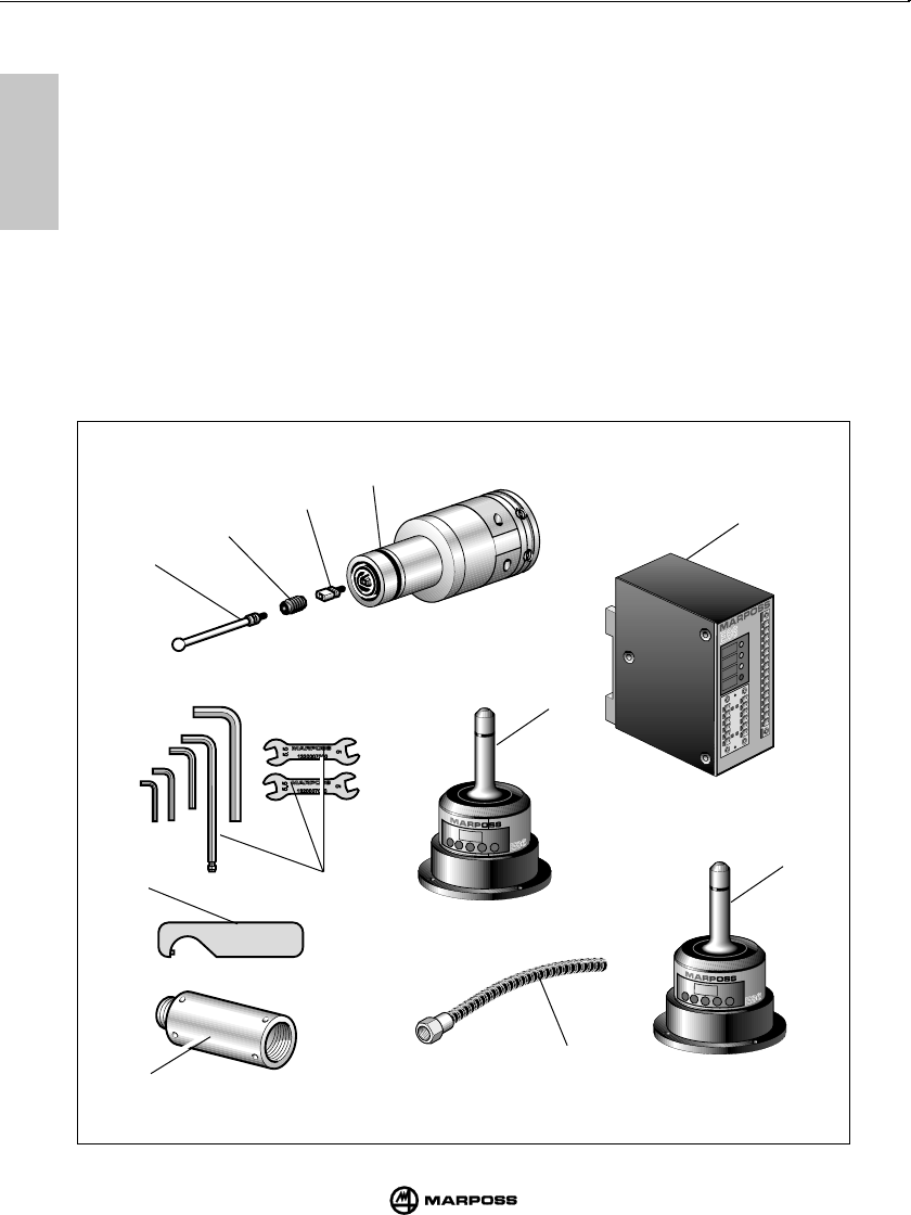
2.1 SYSTEM COMPONENTS
A- Touch probe and E86 transmitter
B- Crash protection pin (optional)
C- Stylus retainer (optional)
D- Stylus
E- E86 antenna
F- E86 interface unit
G- Two, open-ended spanners (CH 5 and 5.5) and a set of Allen keys
H- Special spanner for T25 probe and mechanical extensions
I- Probe extensions (optional)
L-Auxiliary antenna (optional)
M- Anaconda cable sheath for receiver cable (optional)
G
D
C
B
A
F
M
H
I
L
E

11
SYSTEMKOMPONENTEN COMPOSANTS DU SYSTEME
2
2
mida
2.1 COMPONENTI DEL SISTEMA
A- Sonda e trasmettitore E86
B- Spina di rottura (optional)
C- Ritegno braccetto (optional)
D- Braccetto
E- Antenna
F- Unità di interfaccia E86
G- Due chiavi aperte CH 5 - 5.5 e kit chiavi esagonali
H- Una chiave speciale per sonda T25 e prolunghe meccaniche
I- Prolunghe per sonde (optional)
L-Antenna ausiliaria (optional)
M- Guaina tipo "anaconda" di protezione cavo antenna (optional)
2.1 SYSTEMKOMPONENTEN
A- Schaltmeßkopf mit Sendermodul
B- Sollbruchstück (Option)
C- Tasterarmsicherung (Option)
D- Tasterarm
E- Empfängermodul
F- Schnittstelleneinheit E86
G- Zwei Maulschlüssel SW5 - 5,5 und SK-Schlüsselsatz
H- Spezialschlüssel für Schaltmeßkopf T25
I- Verlängerung für Schaltmeßköpfe (Option)
L- Zusatzempfänger (Option)
M- Schutzhülle Typ “Panzerschlauch” für Empfängerkabel (Option)
2.1 COMPOSANTS DU SYSTEME
A- Palpeur et émetteur E86
B- Goupille de rupture (en option)
C- Fixation de sécurité du stylet (en option)
D- Stylet
E- Récepteur E86
F- Unité d’interface E86
G- Deux clés ouvertes CH5 - 5,5 et jeu de clés à six pans
H- Une clé spéciale pour palpeur T25 et rallonges mécaniques
I- Rallonges pour palpeurs (en option)
L- Récepteur auxiliaire (en option)
M- Gaine du type “anaconda” de protection du câble du récepteur (en option)
12
SYSTEM COMPONENTS CONFIGURAZIONE E FUNZIONAMENTO
mida
3
3
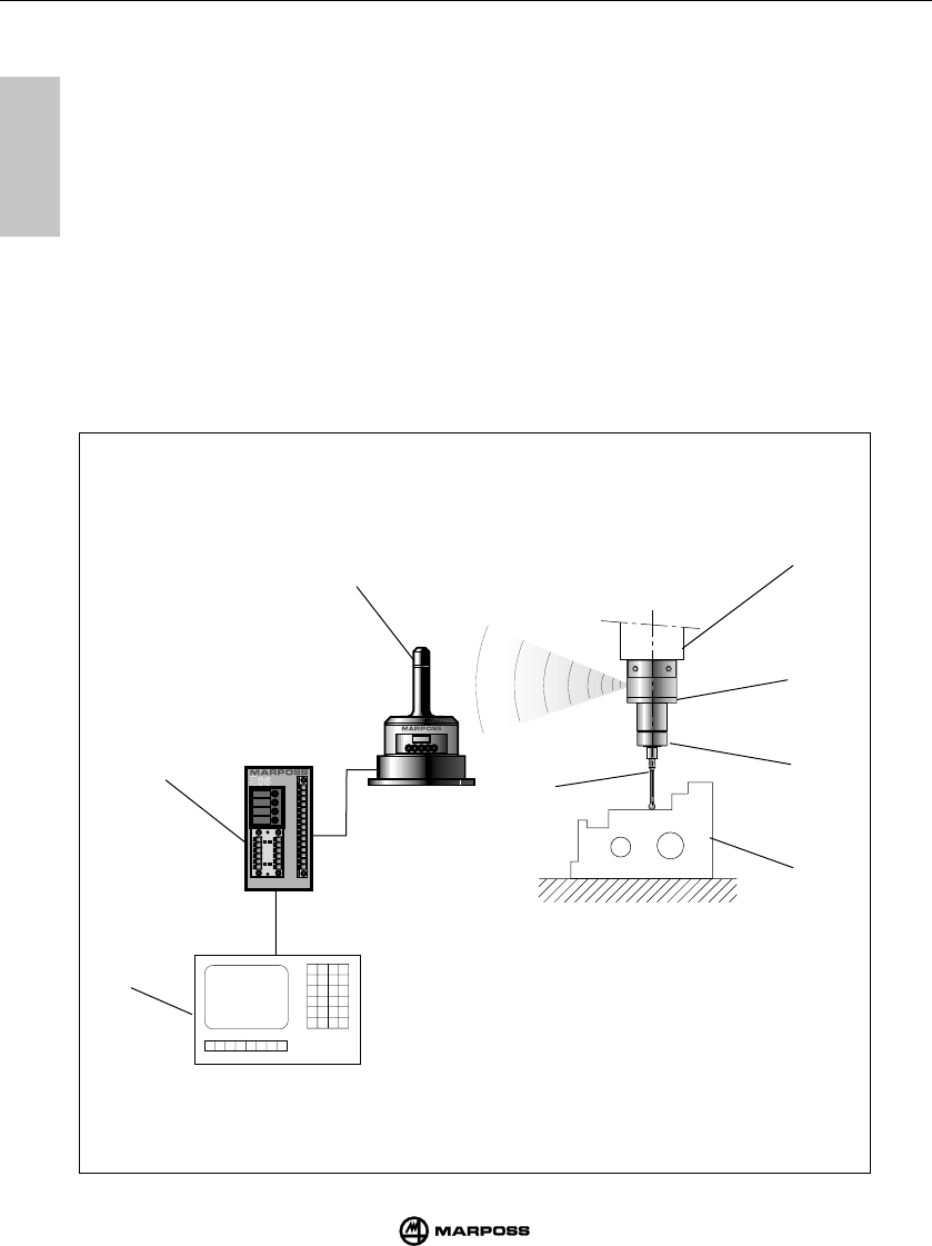
3.1 SYSTEM COMPONENTS
The radio transmission system identifies workpiece coordinate which are processed by the
machine tool CNC in order to define measurements.
The points are detected by a probe consisting of a multi-directional precision microswitch; point
data is then transmitted by a radio transmission system, consisting of a transmitter and receiver,
to an interface unit and from here to the CNC.
The measuring cycle calls up the probe/transmitter unit (mounted on a tool taper) from the tool
magazine and then inserts the unit into the spindle.The system is easy to use and has been
designed for use in hostile industrial environments.The system is designed for use on machining
centers and milling machines for the identification, positioning and measurement of parts still
to be machined and for the measurement of machined parts.
The typical system configuration consists of:
A- Part to be measured E- Machine tool spindle
B- Stylus F- E86 antenna
C- Touch probe G- E86 interface unit
D- E86 transmitter H- Machine tool CNC
A
E
H
tuning
power
probe
low
battery
error
C
D
F
GB

13
AUFBAU UND FUNKTIONSWEISE CONFIGURATION ET FONCTIONNEMENT
mida
3
3
3.1 CONFIGURAZIONE E FUNZIONAMENTO
Il sistema touch con trasmissione radio serve ad identificare dei punti nello spazio che, elaborati da CNC
della macchina utensile, determinano delle misurazioni. Detti punti vengono rilevati dalla sonda, microinter-
ruttore multidirezionale di precisione, e inviati tramite il sistema di trasmissione radio, composto da un
trasmettitore e un ricevitore, all’unità di interfaccia e da questa adattati al CNC. Il ciclo di misura richiama
dal magazzino utensili il gruppo sonda/trasmettitore montato sul portautensile e lo inserisce nel mandrino.
Il sistema è facile da utilizzare ed è progettato per lavorare negli ambienti industriali più ostili. Viene
utilizzato su centri di lavorazione e fresatrici per: l’identificazione, il posizionamento, la misurazione
del pezzo da lavorare e la misurazione del pezzo lavorato.
L’applicazione tipica del sistema è costituita da :
A- Pezzo da misurare E- Mandrino macchina utensile
B- Braccetto F- antenna E86
C- Sonda touch G- Unità di interfaccia E86
D- Trasmettitore E86 H- CNC della macchina utensile
3.1 AUFBAU UND FUNKTIONSWEISE
Das System dient zur Bestimmung von Raumpunkten, welche von der CNC-Steuerung der
Bearbeitungsmaschine für die gewünschten Messungen verarbeitet werden. Diese Punkte werden über
einen Schaltmeßkopf, einen hochpräzisen multidirektionalen Mikroschalter, aufgenommen. Die
entsprechenden Signale werden durch das Funkübertragungssystem, bestehend aus einem Sendermodul
und einem Empfängermodul über die Schnittstelleneinheit an die CNC-Steuerung übertragen. Im Meßzyklus
wird die an einem Werkzunghalter montierte Schaltmeßkopf-/Sendereinheit aus dem Werkzeugmagazin in
die Werkzeugspindel geladen. Das System ist einfach zu bedienen und wurde für den Einsatz im rauhesten
Werkstattbetrieb entwickelt. Es wird in Bearbeitungszentren und Fräsmaschinen für folgende Zwecke
verwendet: Erkennen, Positionieren und Messen des zu bearbeitenden Werkstückes und Hessen des
bearbeiteten Werkstückes.
Die typische Systemapplikation besteht aus folgenden Elementen:
A- Zu messendes Werkstück E- Spindel der Bearbeitungsmaschine
B- Tasterarm F- Empfängermodul
C- Schaltmeßkopf G- Schnittstelleneinheit E86
D- Sendermodul H- CNC-Steuerung der Bearbeitungsmaschine
3.1 CONFIGURATION ET FONCTIONNEMENT
Le système de capteurs avec transmission radio sert à identifier des points dans l’espace qui déterminent
des éléments de mesure après avoir été traités par la CN de la machine-outil. Ces points sont détectés par
le palpeur multi-directionnel de précision, à micro-rupteur, et leurs positions sont envoyées par le système
de transmission radio, se composant d’un émetteur et d’un récepteur, à l’unité d’interface qui les adapte afin
de les faire traiter par la CN. Le cycle de mesure détecte le groupe palpeur/émetteur (monté sur un cône),
dans le magasin des outils et l’introduit sur le mandrin. Le système se caractérise par une utilisation facile,
et il est spécialement conçu pour travailler dans des milieux industriels hostiles.
Il est utilisé pour des centres d’usinage et des fraiseuses pour identifier, positionner et mesurer la
pièce à usiner, ainsi que pour mesurer la pièce usinée.
Dans son application typique, le système se compose des éléments suivants:
A- Pièce à mesurer E- Mandrin de la machine-outil
B- Stylet F- Récepteur E86
C- Palpeur-capteur G- Unité d’interface E86
D- Emetteur E86 H- CN de la machine-outil
4
4
14
SYSTEM OPERATION MODALITÀ DI IMPIEGO
mida
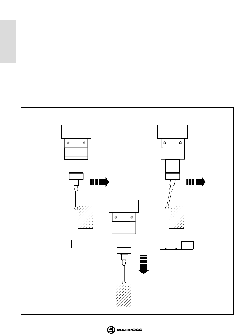
4.1 SYSTEM OPERATION
- This measuring system is multi-directional and operates in the x/y/+z hemisphere.
- The contact between the stylus and the part surface to be tested generates a signal used by
the machine tool to memorise the contact point and stop the machine axes. To ensure a high
degree of repeatability we recommend the use of a constant measuring speed.
- The measuring speed chosen must enable stoppage of the machine axes within the overtravel
limits of the probe used.
- Before using the probe, carry out a calibration cycle to define the systematic error of the probe/
machine tool/CNC system. Systematic error is a characteristic of each measuring direction
and is repeatable; each measurement direction should therefore be calibrated. To calibrate the
system, measure known machine points (R) and then calculate the difference between these
values and the values measured (R+K1). The difference (K1) must be entered in the tool
correction parameters of the CNC and called up whenever a measurement operation in the
related direction takes place.
X/Y
R
Z
K1
X/Y

4
4
15
ANWENDUNGSHINWEISE MODES D’UTILISATION
mida
4.1 MODALITÀ DI IMPIEGO
- Il sistema di misurazione è multidirezionale nell’emisfero x/y/+z.
- Il contatto del braccetto con la superficie del pezzo da ispezionare genera un segnale utilizzato
dalla macchina utensile per memorizzare il punto di contatto e per arrestare gli assi di
macchina. Per avere una buona ripetibilità del sistema si consiglia di utilizzare una velocità di
misura costante.
- La velocità di misura scelta deve consentire un arresto dell’asse macchina entro i limiti di
extracorsa della sonda utilizzata.
- Prima di utilizzare la sonda occorre compensare l’errore sistematico di misura del sistema
composto da sonda, macchina utensile e CNC eseguendo una calibrazione. L’errore sistema-
tico è caratteristico di ogni direzione di misura e ripetibile, perciò la calibrazione deve essere
effettuata in ogni direzione in cui si rileverà la misura. Per calibrare il sistema si consiglia di
misurare dei punti in macchina di valore noto (R) e calcolare le differenze fra questi e i valori
misurati (R+K1). Tale differenza (K1) va inserita nei parametri correttori utensili del CNC e
richiamata ogni volta che si esegue una misura nella stessa direzione.
4.1 ANWENDUNGSHINWEISE
- Es handelt sich um ein multidirektionales, im Bereich x/y/+z frei verfahrbares Meßsystem.
- Berührt der Meßtaster die Werkstückoberfläche, wird ein Schaltsignal erzeugt, welches an die
CNC-Steuerung übertragen wird. Diese registriert den Kontaktpunkt und stoppt die
Maschinenbewegung. Um eine gute Wiederholbarkeit zu gewährleisten, sollten die Meßzyklen
bei konstanter Geschwindigkeit erfolgen
- Die gewählte Meßgeschwindigkeit muß das Anhalten der Maschinenachse innerhalb der
Überlaufgrenzen des eingesetzten Schaltmeßkopfs ermöglichen.
- Vor dem Einsatz muß der systematische Meßfehler für die gesamte Anordnung aus Meßtaster,
CNC-Steuerung und Bearbeitungsmaschine bestimmt werden. Der systematische Fehler ist
der Differenzbetrag zwischen Sollposition und tatsächlicher Antastposition. Aus diesem Grund
ist der systematische Messfehler in jeder zu verfahrenden Achse bzw. Meßrichtung zu
bestimmen. Dazu wird empfohlen, bekannte Maschinenpunkte (R) zu wählen und die Differenz
zu den aufgenommenen Koordinaten (R+K1) zu berechnen. Die Differenzwerte (K1) sind in die
CNC-Parameter für die Werkzeugkorrektur zu übernehmen, werden also in den
durchzuführenden Messungen berücksichtigt.
4.1 MODES D’UTILISATION
- Le système de mesure est du type multi-directionnel dans l’hémisphère x/y/+z.
- Lorsque le stylet entre en contact avec la surface à contrôler, il fournit un signal qui sera utilisé
par la machine-outil pour mémoriser le point de contact et arrêter les axes de machine. Pour
obtenir une bonne possibilité de répétition du système, il est recommandé de maintenir
constante la vitesse de mesure.
- La vitesse de mesure sélectionnée doit permettre un arrêt de l’axe machine à l’intérieur des
limites d’extra-course du palpeur utilisé.
- Avant d’utiliser le palpeur, il faut déterminer l’erreur systématique de mesure du système se
composant du palpeur, de la machine-outil et de la CN en effectuant un étalonnage. L’erreur
systématique est spécifique à chaque direction de mesure et avec possibilité de répétition:
l’étalonnage doit être effectué dans toutes les directions d’acquisition de la mesure. Pour
étalonner le système, il est recommandé de mesurer des points sur la machine de valeurs
connues (R), et de calculer la différence entre celles-ci et les valeurs mesurées (R+K1). Cette
différence (K1) doit être introduite dans les paramètres de correction des outils de la CN et
activée à chaque fois que l’on effectue une mesure dans la même direction.

5
5
16
MEASUREMENT PROBE SONDA DI MISURA
mida
5.1 MEASUREMENT PROBE
The measurement probe is a multi-directional precision microswitch used on Numeric Control
(NC) metal cutting machine tools for testing and measuring tools and workpieces.
Four different models of multi-directional touch probes operating in the x/y/+z hemisphere are
available; the four models have different dimensions and overtravel value.
For each probe model there are two versions with different front guards as follows:
-Version "G" with cloth-backed gasket providing protection against coolant.
-Version "S" with metal chip guard.
There is therefore a specific probe to match all machine tool needs as follows.
- Probe T25G - Probe T25S
- Probe TL25G - Probe TL25S
- Probe T36G - Probe T36S
- Probe T60G - Probe T60S
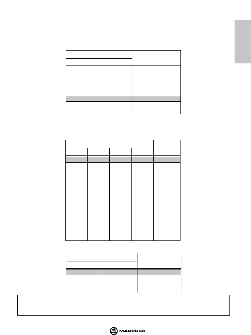
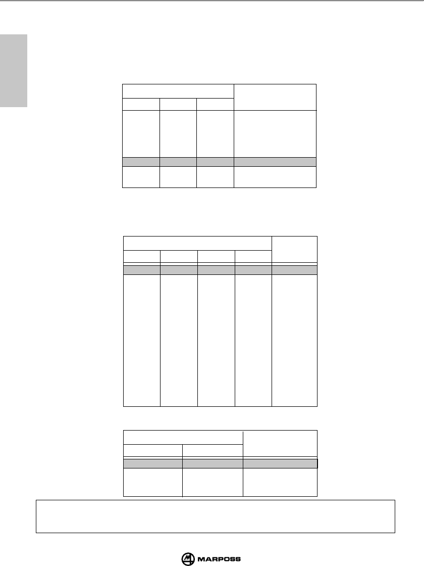
PROBE CHARACTERISTICS
Probe type T25 TL25 T36 T60
Probe axes ±X, ±Y, +Z±X, ±Y, +Z±X, ±Y, +Z±X, ±Y, +Z
Unidirectional probe repeatability (2 σ)
with speeds up to 600 mm/min 1 µm1 µm1 µm1 µm
Measuring force on X, Y plane 200 gf 90 gf 260 gf 280 gf
Measuring force in Z direction 1200 gf 550 gf 1200 gf 1200 gf
Overtravel on X, Y plane 11.2 mm 11.2 mm 14.4 mm 22 mm
Overtravel in Z direction 4 mm 4 mm 4.2 mm 6.4 mm
C
HARACTERISTICS
FOR
STYLUS
LENGTH
35 mm 35 mm 40 mm 50 mm
IEC protection rating IP67 IP67 IP67 IP67
5.1 SONDA DI MISURA
La sonda di misura è un microinterruttore multidirezionale di precisione utilizzata nelle applica-
zioni su macchine ad asportazione di truciolo a CN, per il controllo e la misura di utensili e pezzi.
Sono disponibili quattro diversi modelli di sonde touch multidirezionali nell’emisfero x/y/+z che
differiscono per dimensioni e valore di extracorsa del braccetto. Per ciascun modello di sonda
esistono due differenti versioni a seconda del tipo di protezione frontale:
-“Versione G” con guarnizione telata per una migliore protezione contro il liquido refrigerante.
-“Versione S” con scudo metallico di protezione ai trucioli.
Per risolvere in modo ottimale le specifiche esigenze che si manifestano sulle differenti macchi-
ne utensili, sono disponibili le seguenti sonde:
- Sonda T25G / T25S
- Sonda TL25G / TL25S
- Sonda T36G / T36S
- Sonda T60G / T60S
CARATTERISTICHE SONDA
Tipo sonda T25 TL25 T36 T60
Assi sonda
±
X,
±
Y, +Z
±
X,
±
Y, +Z
±
X,
±
Y, +Z
±
X,
±
Y,+Z
Ripetibilità unidirezionale sonda (2
σ
)
con velocità fino a 600 mm/min. 1
µ
m1
µ
m1
µ
m1
µ
m
Forza di misura nel piano X, Y 200 gf 90 gf 260 gf 280 gf
Forza di misura nella direzione Z 1200 gf 550 gf 1200 gf 1200 gf
Extracorsa nel piano X, Y 11,2 mm 11,2 mm 14,4 mm 22 mm
Extracorsa nella direzione Z4 mm 4 mm 4,2 mm 6,4 mm
C
ARATTERISTICHE
RIFERITE
AL
BRACCETTO
DI
35 mm 35 mm 40 mm 50 mm
Grado di protezione secondo norme IEC IP67 IP67 IP67 IP67

5
5
17
SCHALTMESSKÖPFE PALPEUR DE MESURE
mida
5.1 SCHALTMESSKÖPFE
Der Schaltmeßkopf ist ein hochpräziser multidirektionaler Mikroschalter, der bei NC-gesteuerten spanenden
Maschinen zur Kontrolle und Messung von Werkzeugen und Werkstücken verwendet wird.
Es sind vier frei im Bereich x/y/+z verfahrbare Schaltmeßkopftypen verfügbar, die sich in den Abmessungen
und im Tasterüberlauf unterscheiden.
Jedes Meßkopfmodell gibt es in zwei verschiedenen
Ausführungen entsprechend der vorderen Schutzkappe:
-“Ausführung G” mit gewebeverstärkter Gummidichtung zum besseren Schutz gegen Kühlmittel
-“Ausführung S” mit Metallschild-Abdeckung zum Schutz gegen Späne.
Entsprechend den jeweiligen Anforderungen der Bearbeitungsmaschine stehen folgende
Schaltmeßkopftypen zur Verfügung:
-T25G / T25S
-TL25G / TL25S
-T36G / T36S
-T60G / T60S
TECHNISCHE MERKMALE DER SCHALTMESSKOPFE
Schaltmeßkopftyp T25 TL25 T36 T60
Meßkopfachsen ±X, ±Y, +Z±X, ±Y, +Z±X, ±Y, +Z±X, ±Y, +Z
Wiederholbarkeit in einer Richtung (2 σ)
bei einer Geschwindigkeit bis 600mm/min
1 µm1 µm1 µm1 µm
Meßkraft in X, Y 2 N 0,9 N 2,6 N 2,8 N
Meßkraft in Z12 N 5,5 N 12 N 12 N
Überlauf in X, Y11,2 mm 11,2 mm 14,4 mm 22 mm
Überlauf in Z4 mm 4 mm 4,2 mm 6,4 mm
A
NGABEN
BEZOGEN
AUF
T
ASTERARMLÄNGE
35 mm 35 mm 40 mm 50 mm
Schutzart nach IEC-Norm IP67 IP67 IP67 IP67
5.1 PALPEUR DE MESURE
Le palpeur de mesure est un micro-rupteur multi-directionnel de précision utilisé dans les
applications sur des machines à enlèvement de copeaux à CN, pour effectuer le contrôle et la
mesure d’outils et de pièces. Quatre différents types de palpeurs-capteurs multi-directionnels
sont disponibles dans l’hémisphère x/y/+z, de dimensions et extra-courses différentes.
Pour chaque modèle de palpeur, il existe deux versions différentes suivant le type de protection à l’avant:
-“Version G” avec joint toilé pour une meilleure protection contre le liquide de refroidissement.
-“Version S” avec protection métallique contre les copeaux.
Pour satisfaire d’une manière optimale aux exigences spécifiques des différentes machines-
outils, les palpeurs suivants sont disponibles:
· Palpeur T25G - Palpeur T25S
· Palpeur TL25G - Palpeur TL25S
· Palpeur T36G - Palpeur T36S
· Palpeur T60G - Palpeur T60S
CARACTERISTIQUES DU PALPEUR
Type de palpeur T25 TL25 T36 T60
Axes du palpeur
±
X,
±
Y,
+
Z
±
X,
±
Y,
+
Z
±
X,
±
Y,
+
Z
±
X,
±
Y,
+
Z
Répétabilité unidirectionnelle du palpeur
(2
σ
) avec vitesse jusqu’à 600 mm/min
1
µ
m1
µ
m1
µ
m1
µ
m
Force de mesure dans le plan X,Y 200 gf 90 gf 260 gf 280 gf
Force de mesure dans la direction Z 1200 gf 550 gf 1200 gf 1200 gf
Extra-course dans le plan X,Y 11,2 mm 11,2 mm 14,4 mm 22 mm
Extra-course dans la direction Z 4 mm 4 mm 4,2 mm 6,4 mm
C
ES
CARACTÉRISTIQUES
SE
RÉFÈRENT
À
UN
STYLET
DE
35 mm 35 mm 40 mm 50 mm
Degré de protection suivant les normes CEI
IP67 IP67 IP67 IP67
18
6
mida
6
RADIO TRANSMISSION TRASMISSIONE RADIO
BAD
C
power
probe
low
battery
error
t
un
in
g
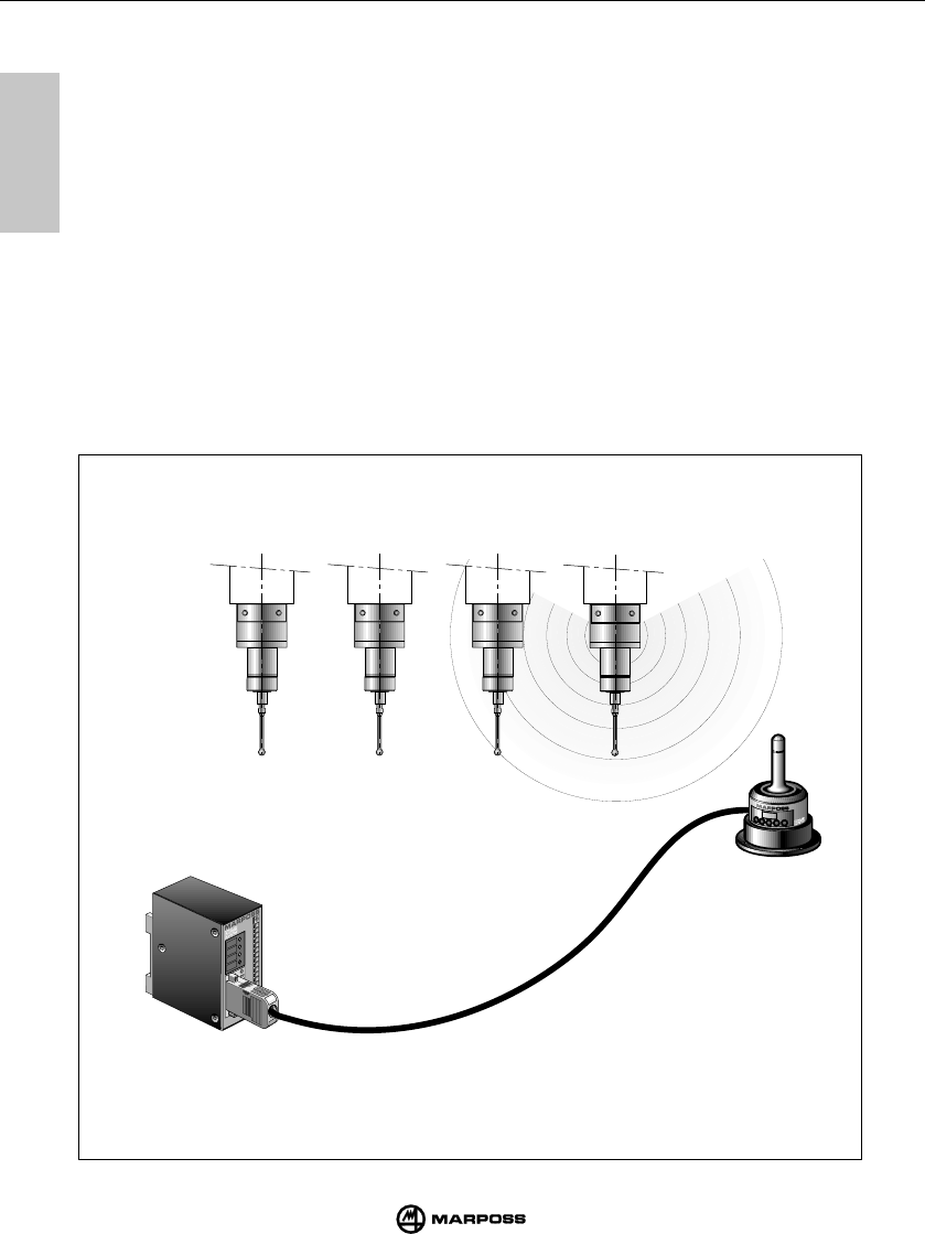
6.1 DESCRIPTION
The radio transmission system consists of three items:
• Transmitter: detect the data needed to the CNC for the measure determination.
• Antenna: receive the transmitter signal and send it to the E86 interface unit.
• Interface unit: processes the signals received from the antenna and transmit them to the CNC.
By means of dip-switch or with M-Code (see chapt. 9.4 "Programming the Interface unit") it is possible to select
16 different radio transmission channels. Two antennas can be connected to the E86 interface unit to enlarge
the transmission range and improve communication reliability.
The E86 system allows the use of up to four transmitters on a single machine tool working on the same radio
transmission channel and individually activated by a different identification code signal (see also chapt. 7.3
"Programming the transmitter"). Systems working on adjacent machines have to be programmed with different
transmission channels to allow interference free operation. The distance between systems working on adjacent
channels (eg. CH 5 and CH 6) must be higher than 3 m and 1m for the channels not adjacent. The distance
between systems working on the same channel must be higher than 100m.
Technical Features
- Transmission distance: 10 m - Transmission channel: 16
- Activation distance: 2m - Transmission frequency: from 912.2 to 916.8 MHz
or from 910.2 to 918.8 MHz according to the model

19
6
mida
6
ÜBERTRAGUNG TRANSMISSION RADIO
6.1 DESCRIZIONE
Il sistema di trasmissione radio è composto da tre elementi:
• Trasmettitore: emette le informazioni necessarie al CNC per l' elaborazione della misura.
• Antenna: riceve il segnale del trasmettitore e lo invia all' unità di interfaccia E86.
• Unità di interfaccia: elabora i segnali e li converte in una forma utilizzabile dal CNC.
Il sistema E86 permette la programmazione di 16 diversi canali di trasmissione selezionabili mediante alcuni dip-
switch o con segnale da logica (vedi cap. 9.4 "Programmazione dell'unità di interfaccia").
Per aumentare il campo di trasmissione e l'affidabilità della comunicazione radio, è possibile collegare due
antenne all' unità di interfaccia E86. Il sistema permette di utilizzare fino ad un massimo di 4 trasmettitori sulla
stessa macchina utensile, funzionanti sullo stesso canale e attivabili alternativamente, uno alla volta, mediante un
differente codice di identificazione (vedi cap. 7.3 "Programmazione del trasmettitore"). Per evitare interferenze
sistemi operanti su macchine adiacenti devono essere programmati su un diverso canale di trasmnissione. La
distanza fra sistemi funzionanti su canali adiacenti (per es. CH5 e CH 6) deve essere superiore a 3 m ed 1 metro
per i canali non adiacenti. La distanza tra sistemi operanti sullo stesso canale deve essere superiore a 100 m.
Caratteristiche tecniche
- Distanza di trasmissione: 10 m. - Numero canali di trasmissione: 16
- Distanza di attivazione: 2 m. - Frequenza di trasmissione: da 912.2 a 916.8 MHz o da 910.2
a 918.8 MHz in base al modello
6.1 BESCHREIBUNG
Das Funkübertragungssystem besteht aus folgenden Komponenten:
• Sendermodul; überträgt die für die Meßwertverarbeitung erforderlichen Daten zur CNC-Steuerung.
• Empfängermodul; empfängt das vom Sender übertragene Signal und leitet es zur E86 Schnittstelleneinheit
weiter.
• Schnittstelleneinheit; verarbeitet die Signale und konvertiert diese in eine CNC-kompatible Form.
Über Dip-Schalter oder Logiksignale (siehe Kapitel 7.3 und 9.4) können 16 verschiedene Frequenzkanäle
gewählt werden. Das System verwaltet bis zu vier Sender auf einer Maschine, die jeweils einzeln über
Logiksignale anwählbar sind; entweder mit vier Identifikatioscodes auf einem einzigen Kanal oder mit je einem
Identifikatioscode auf vier Kanälen. Systeme auf nebeneinanderstehenden Maschinen müssen auf
unterschiedliche Kanäle programmiert werden. Der Minimalabstand bei nebeneinander liegenden Kanälen
(z.B. Kanal 5 und 6) ist 3 m, bei weiter entfernt liegenden Kanälen 1 m. Wenn mehrere Systeme auf demselben
Frequenzkanal betrieben werden, sollte der Abstand zwischen den Systemen mindestens 100 m betragen, um
eventuelle Interferenzen zu vermeiden. Um den Übertragungsbereich zu erweitern und die Zuverlässigkeit zu
erhöhen, lassen sich an die E86 Schnittstelleneinheit zwei Empfänger anschließen.
Technische Merkmale
- Übertragungsstrecke: 10 m. - Anzahl Übertragungskanäle: 16
- Aktivierungsabstand: 2 m. - Übertragungsfrequenz: von 912.2 bis 916.8 MHz oder
von 910.2 bis 918.8 MHz nach dem Modell
6.1 DESCRIPTION
Le système d'émission radio comporte trois éléments :
• Emetteur : émet les informations nécessaires à la CNC pour l'élaboration de la mesure.
• Récepteur : reçoit le signal de l'émetteur et l'envoie à l'interface E86.
• Interface : élabore les signaux et les traduit à la CNC.
Le système E86 permet de programmer 16 différents canaux de transmission par des interrupteurs ou à l’aide
d’un signal de logique (voir chapitre 9.4 “Programmation de l’unité d’interface”). Pour augmenter la plage de
transmission et la fiabilité de la communication radio, il est possible de raccorder deux antennes à l’interface
E86. Le système permet de gérer jusqu’à 4 émetteurs max. sur la même machine, fonctionnant sur le même
canal et pouvant être sélectionnés un par un moyennant un différent code d’identification (voir chapitre 7.3
“Programmation de l’émetteur”). Le système permet de programmer 16 canaux de transmission différents. Afin
d’éviter des interférences, les systèmes fonctionnant sur des machines adjacentes doivent être programmées
sur un canal de transmission différent. La distance entre les systèmes fonctionnant sur des canaux adjacents
(par ex. CH5 et CH6) doit supérer 3 mètres et 1 mètre pour les canaux non adjacents. La distance entre les
systèmes fonctionnant sur le même canal doit supérer 100 mètres.
Caractéristiques techniques
- Distance de transmission: 10 m. - Nombre de canaux de transmission: 16
- Distance d'activation: 2 m. - Fréquence de transmission: de 912.2 jusqu’à 916.8 MHz
ou de 910.2 jusqu’à 918.8 MHz selon le modèle
20
6
mida
6
RADIO TRANSMISSION TRASMISSIONE RADIO
H
t
un
in
g
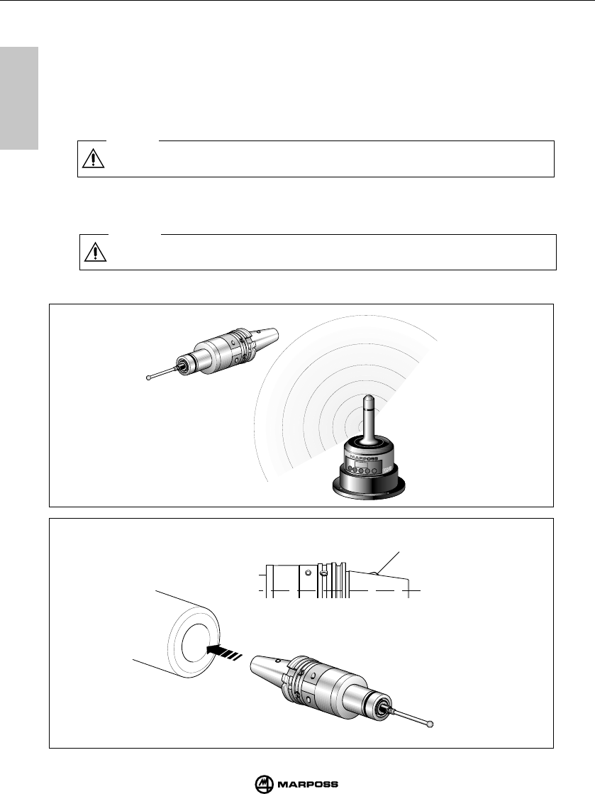
6.2 TRANSMISSION ACTIVATION
The transmitter is usually in the stand-by mode; transmission is started in one of the following ways depending on the
transmitter version:
•
radio starting
•
mechanical starting (by micro-switch on the taper shank).
6.2.1 RADIO STARTING
The system is activated by a radio signal emitted from the antenna to the transmitter. The transmission is started by a
signal from the machine logic (START input signal - M code).
6.2.2 MECHANICAL STARTING
The taper shank of the probe/transmitter assembly is fitted with a microswitch (H).
Inserting the shank into the spindle triggers the microswitch and starts transmission.
Caution
When the transmitter is returned to the tool magazine ensure that the microswitch cannot be triggered.
Caution
In case of multiple transmitter installed on the same machine during the activation phase the distance
between them must be higher than 5 m.
21
6
mida
6
ÜBERTRAGUNG TRANSMISSION RADIO
6.2 ATTIVAZIONE DELLA TRASMISSIONE
Il trasmettitore è normalmente in condizione di attesa (stand-by); l’attivazione della trasmissione può avvenire in due
modi a seconda della versione di trasmettitore:
•attivazione radio
•attivazione meccanica (microinterruttore sul cono portautensili)
6.2.1 ATTIVAZIONE RADIO
L’attivazione del sistema avviene a seguito dell' invio di un segnale radio dall' antenna al trasmettitore. Il comando di
attivazione del sistema (START) è generato dall'unità di interfaccia mediante il collegamento alla logica di macchina
(segnale di ingresso START - codice M).
6.2.2 ATTIVAZIONE MECCANICA
Sul cono portautensile è presente un microinterruttore (H).L’inserimento del cono nel mandrino causa l’attivazione della
trasmissione.
6.2 AKTIVIERUNG DER ÜBERTRAGUNG
Das am Schaltmeßkopf angebaute Sendermodul befindet sich normalerweise in Bereitschaft (Stand-by-Betrieb); die
Aktivierung der Übertragung kann je nach Senderversion auf eine der folgenden Weisen erfolgen:
•Funkaktivierung
•mechanische Aktivierung durch Mikroschalter am Steilkegel
6.2.1 FUNKAKTIVIERUNG
Die Systemaktivierung erfolgt durch ein Funksignal, das vom Empfängermodul zum Sender übertragen wird. Das
Aktivierungssignal (START) wird von der Schnittstelleneinheit durch Anschluß an die Maschinenlogik erzeigt
(Eingangssignal START - M Code).
6.2.2 MECHANISCHE AKTIVIERUNG
Im Steilkegel befindet sich ein Mikroschalter (H). Die Aktivierung der Übertragung erfolgt, wenn der Steilkegel in die
Spindel eingeführt wird.
6.2 ACTIVATION DE L’EMISSION
L’émetteur est normalement en état d’attente (stand-by); l’activation de l’émission peut se faire dans l’un des modes
suivants, selon la version de l’émetteur:
•
activation radio
•
activation mécanique (micro-interrupteur sur le cône porte-outils)
6.2.1 ACTIVATION RADIO
L'activation du système a lieu après l'envoi d'un signal radio de l'antenne à l'émetteur. La commande d'activation du
système (START) est engendrée par l'interface via la logique de machine (signal d'entrée START - code M).
6.2.2 ACTIVATION MECANIQUE
Un micro-interrupteur (H) est monté sur le cône porte-outils.
L’émission est activée au moment où l’introduction du cône dans le mandrin actionne ce micro-interrupteur.
Avvertenza
Se più trasmettitori sono utilizzati sulla stessa macchina con attivazione mediante codice di identificazione
è necessario che durante l’attivazione la loro distanza sia superiore a 5 m.
Avvertenza
Quando si ripone il trasmettitore nel magazzino utensili assicurarsi che non venga azionato
il microinterruttore di attivazione.
Vorsicht
Bei mehreren Sendermodulen auf einer Maschine muß während der Aktivierung der Abstand zwischen ihnen
mehr als 5 m betragen.
Vorsicht
Es ist darauf zu achten, daß der Mikroschalter im Steilkegel nicht gedrückt werden kann, während sich das
Sendermodul mit seinem Steilkegel im Werkzeugmagazin befindet, da sonst die Batterielebensdauer
verkürzt wird.
Mise en garde
S’assurer que le micro-interrupteur d’activation ne soit pas actionné quand on place l’émetteur dans le
magasin des outils.
Mise en garde
Si de différents émetteurs sont utilisés sur la même machine qui est activée par un code d’identification, il
est nécessaire que pendant l’activation leur distance soit supérieure à 5 m.
22
6
mida
6
RADIO TRANSMISSION TRASMISSIONE RADIO
6.3 STOPPING TRANSMISSION
When the transmitter is not in use it is switched to the stand-by mode in order to prolong battery
life.
Transmitter with radio starting
• Automatic stopping
The transmitter is automatically switched off when the time-out set on the transmitter timer
during starting has elapsed (see Transmitter programming).
Transmission with mechanical starting
• Mechanical stopping
Transmission is stopped when the transmitter is removed from the spindle and the microswitch
on the taper shank is released.

23
6
mida
6
ÜBERTRAGUNG TRANSMISSION RADIO
6.3 DISATTIVAZIONE DELLA TRASMISSIONE
Quando il trasmettitore non è usato si disattiva (condizione di stand-by) per prolungare la vita
della batteria.
Trasmettitore con attivazione radio
• Disattivazione automatica
La disattivazione avviene allo scadere del tempo impostato sul timer del trasmettitore (vedere
“Programmazione del trasmettitore”).
Trasmettitore con attivazione meccanica
• Disattivazione meccanica
La disattivazione avviene quando il trasmettitore viene estratto dal mandrino.
6.3 ABSCHALTEN DER ÜBERTRAGUNG
Wenn das Sendermodul, und damit meistens auch der Schaltmeßkopf, nicht benötigt wird, sollte
es abgeschaltet bzw. in Bereitschaft umgeschaltet werden, um eine möglichst lange Lebensdauer
der Batterie zu gewährleisten.
Sendermodul mit Funkaktivierung
• Automatische Abschaltung
Die Abschaltung der Übertragung erfolgt nach Ablauf der im Sendermodul programmierten Zeit
(siehe “Programmierung des Senders”). Die Zeit beginnt jeweils mit dem Start der Übertragung
oder mit dem letzten Antasten.
Sender mit mechanischer Aktivierung
• Abschaltung über Schalter
Die Abschaltung erfolgt bei der Entnahme des Senders aus der Spindel (der Mikroschalter auf
dem Steilkegel schaltet aus).
6.3 DESACTIVATION DE L’EMISSION
Pour prolonger au maximum la durée de vie de la batterie, il est recommandé de désactiver
l’émetteur (condition de stand-by) en cas de non utilisation.
Emetteur avec activation radio
• Désactivation automatique
La désactivation a lieu à la fin du temps programmé sur le temporisateur de l’émetteur (voir
“Programmation de l’émetteur”) à compter du moment d’activation.
Emetteur avec activation mécanique
• Désactivation mécanique
La désactivation a lieu au moment de la dépose de l’émetteur du mandrin (le micro-interrupteur
sur le cône porte-outil est relâché).
7
7
24
E86 TRANSMITTER TRASMETTITORE E86
mida
7.1 DESCRIPTION
The transmitter optically transmits the measurement data to be processed by the CNC to the antenna (see “Optical
Transmission”). This data includes:
- Probe status: contact open/contact closed
- Battery status: battery low or discharged
A Green LED indicate the probe, battery and transmission status.
LED constant lit = Probe deflected
1 Flash every 2secs. = transmission activated
2 Flash every 2secs. = battery low
Two types of transmitter are available:
-Transmitter with radio activation.
Transmission is started by a radio signal sent from the antenna
-Transmitter with mechanical activation.
The transmission is started by a microswitch (H) mounted on the shank
Technical features
- Power suppl: 9V battery
- Transmisson distance 10 m
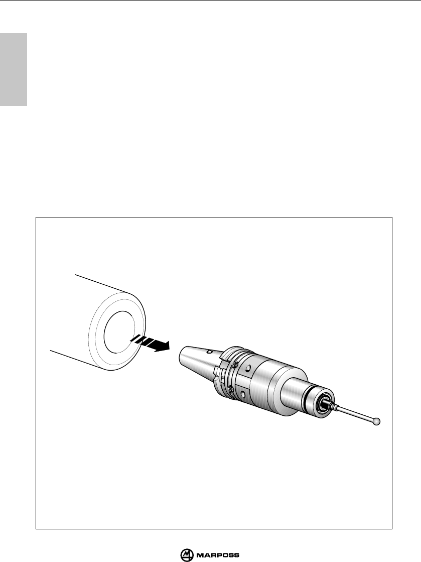
Battery connection
The battery is housed in the battery compartment. To change the battery, unscrew the two screws (G) and remove the
cover marked with battery symbol (F).
G
H
F

7
25
SENDERMODUL EMETTEUR E86
mida
7
7.1 DESCRIZIONE
Il trasmettitore invia all'antenna le seguenti informazioni necessarie al CNC per l’elaborazione della misura:
- Stato della sonda: contatto aperto/contatto chiuso
- Stato della batteria: carica o quasi scarica
Un LED verde indica lo stato della sonda, della batteria e della trasmissione:
LED acceso permanente = Sonda deflessa
1 impulso ogni 2s = Trasmissione attivata
2 impulsi ogni 2s = Batteria quasi scarica
Sono disponibili due tipi di trasmettitore:
-Trasmettitore con attivazione radio. La trasmissione viene attivata da un segnale inviato dall'antenna.
-
Trasmettitore con attivazione meccanica. La trasmissione viene attivata mediante il microinterruttore (H) posto sul cono
portautensili.
Il microinterruttore non è presente nel trasmettitore con attivazione radio.
Caratteristiche tecniche
- Alimentazione: batteria 9 V
- Distanza di trasmissione: 10 m
Inserimento batteria
Rimuovere il coperchio (F) contrassegnato dal simbolo grafico della batteria svitarando le due viti (G). Innestare la
batteria negli appositi contatti del coperchio e riavvitare le viti
7.1 BESCHREIBUNG
Die Daten zur Verarbeitung der Meßwerte für die CNC-Steuerung werden vom Sendermodul an das Empfängermodul
übertragen. Diese Daten sind:
- Status des Schaltmeßkopfes: Kontakt offen/Kontakt geschlossen
- Batterieladezustand: leer oder fast leer
Eine LED (grün) zeigt den Status des Schaltmeßkopfes an:
LED dauernd leuchtend = ausgelenkt
1 impuls alle 2sec = aktivierte Übertragung
2 impulse alle 2sec = schwache Batterie
Es sind verschiedene Sendertypen verfügbar:
-Sendermodul mit Funkaktivierung. Die Übertragung wird durch ein Signal vom Empfängermodul aktiviert.
-Sendermodul mit mechanischer Aktivierung. Die Übertragung wird über einen Mikroschalter (H) auf dem Werkzeughalter
aktiviert. Bei Funkaktivierung ist dieser Mikroschalter nicht vorhanden.
Technische Merkmale
- Versorgung: 9 V-Batterie
- Übertragungsstrecke: 10 m
Einsetzen der Batterie
Die Abdeckung (F) mit dem Batteriesymbol nach Lösen der zwei Schrauben (G) abnehmen. Die Batterie in die
entsprechenden Kontakte der Abdeckung einsetzen und die Schrauben wieder eindrehen.
7.1 DESCRIPTION
L’émetteur transmet par voie radio au récepteur les informations nécessaires à la CNC pour le traitement de la mesure,
et notamment:
- l'état de la sonde: contact ouvert / contact fermé;
- l'état de la batterie: chargée ou presque déchargée.
Une LED verte indique l'état de la sonde, de la batterie et de la transmission:
LED allumée sans clignoter = sonde fléchie
1 impulsion toutes les 2s = transmission active
2 impulsions toutes les 2s = batterie presque déchargée
Il existe deux types d'émetteur:
-L'émetteur à activation radio où la transmission est activée par un signal envoyé par l'antenne;
-L'émetteur à activation mécanique où la transmission est activée avec un microrupteur (H) sur le cône porte-outils.
L'émetteur à activation radio ne possède pas de microrupteur.
Caractéristiques techniques
- Alimentation: batterie 9 V
- Distance de transmission: 10 m
Mise en service de la batterie
Oter le couvercle (F) avec le symbole graphique de la batterie dévissant les deux vis (G). Connecter la batterie sur les contacts
du couvercle et resserrer les vis.
7
7
26
E86 TRANSMITTER TRASMETTITORE E86
mida
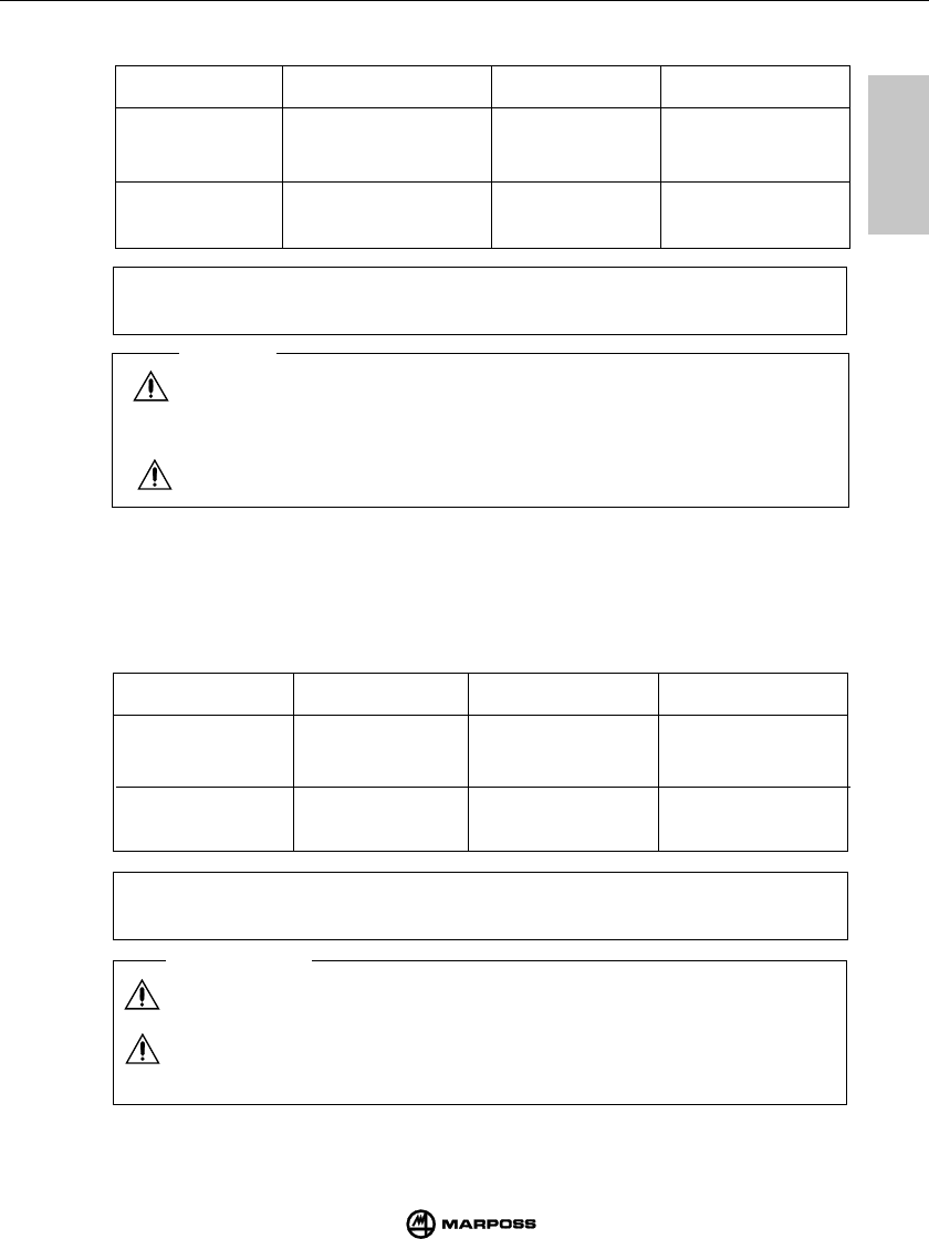
Alcalina Duracell MN1604 65 ore 85 giorni
Philips 1604
Varta 4022
Litio Tadiran TL5306 146 ore 190 giorni
Kodak U9VL
STAND-BY
OPERATION
CONTINUOUS
OPERATION
RECOMMENDED
BRAND
BATTERY
TYPE
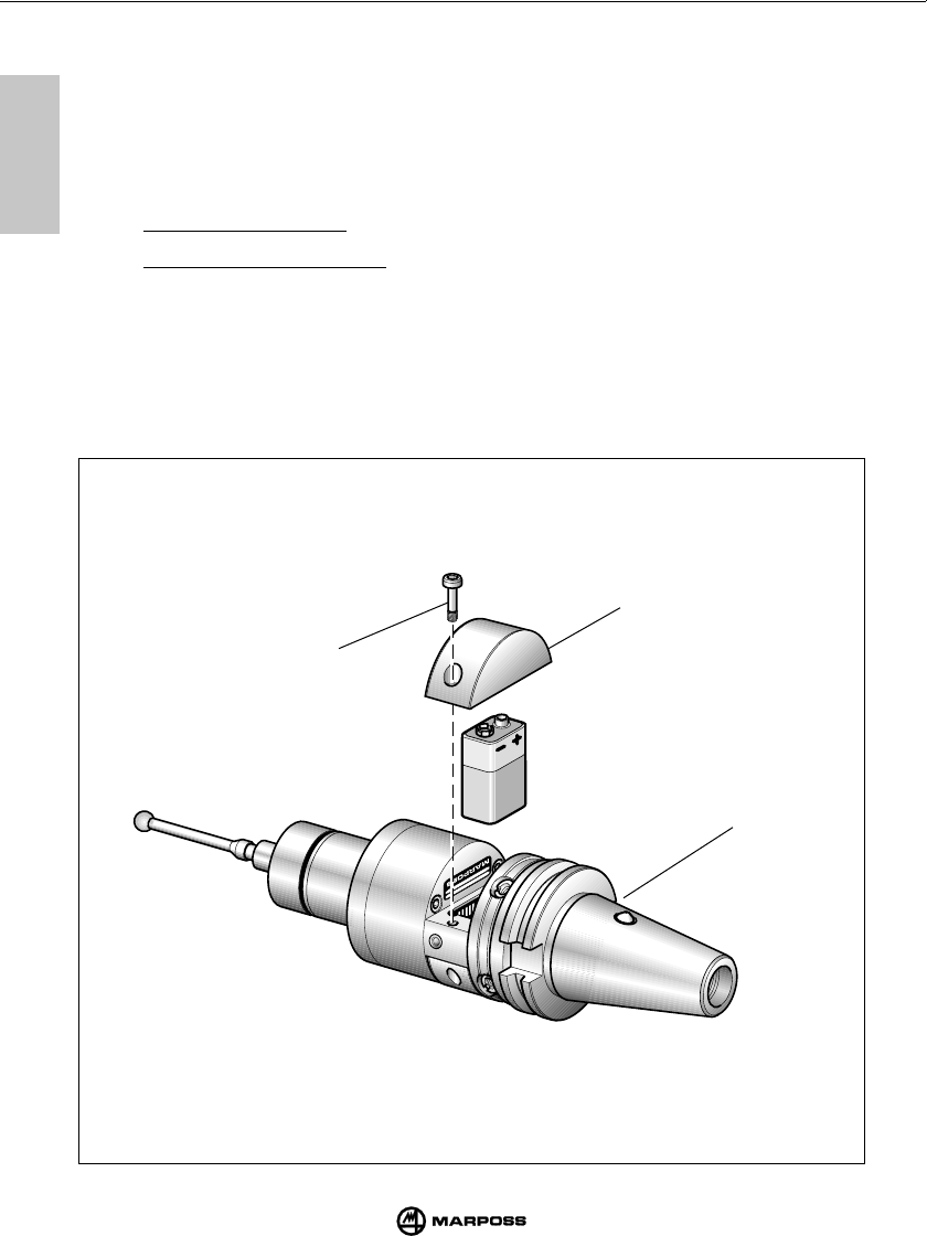
Caution
TRANSMITTER WITH MECHANICAL TRIGGERING
Check that the shape of the tool magazine taper does not interfere with or trigger
the micro-switch (H).
LITHIUM BATTERY : Danger of explosion if lithium battery is incorrectly replaced.
Replace only with the same or equivalent type recommended (see table). Dispose
of used batteries in compliance to the regulations in force.
Battery life depends on the length of transmitter operating time and the type of
battery used.
The table shows battery life on the basis of battery type with the transmitter operating
in the continuous and stand-by modes; the values shown are based on experience.
Note:
The transmitter is delivered complete with an alcaline battery placed inside the
package. Fit the battery on the transmitter before its installation (see “Fitting/
changing the transmitter battery”).
7.2 BATTERY LIFE
7.2 DURATA DELLA BATTERIA
FUNZIONAMENTO
STAND-BY
FUNZIONAMENTO
CONTINUO
BATTERIA
CONSIGLIATA
TIPO
BATTERIA
Avvertenza
TRASMETTITORE CON ATTIVAZIONE MECCANICA
Verificare che la sede del cono nel magazzino utensili abbia una conformazione
tale da evitare l’azionamento del microinterruttore (H) di attivazione.
BATTERIE AL LITIO : Le batterie al litio possono esplodere se non sostituite in modo
corretto. Sostituire solo con tipo uguale o equivalenti (vedi tabella). Eliminare le
batterie usate in conformità con le normative vigenti.
Nota:
Una batteria alcalina è fornita con il trasmettitore all' interno dell'imballo.Inserire la
batteria nel trasmettitore prima dell’ installazione (vedere “Inserimento/sostituzione
batteria trasmettitore”)
La durata della batteria dipende dal tempo di utilizzo del trasmettitore e dal tipo di
batteria utilizzata. Nella tabella sono riportati i valori di durata in funzione della
batteria e in condizione di funzionamento continuo e stand-by del trasmettitore .
Alkaline Duracell MN1604 65 hours 85 days
Philips 1604
Varta 4022
Lithium Tadiran TL5306 146 hours 190 days
Kodak U9VL
7
27
SENDERMODUL EMETTEUR E86
mida
7
Alcaline Duracell MN1604 65 heures 85 jours
Philips 1604
Varta 4022
Lithium Tadiran TL5306 146 heures 190 jours
Kodak U9VL
Alkali Duracell MN1604 65 Stunden 85 Tage
Philips 1604
Varta 4022
Lithium Sonnenschein - SLM9V 146 Stunden 190 Tage
Tadiran TL5306
Kodak U9VL
7.2 LEBENSDAUER DER SENDERMODULBATTERIE
EMPFOHLENE
BATTERIE STAND-BY-BETRIEBDAUERBETRIEBBATTERIEART
Hinweis:
Bei Auslieferung ist die Batterie nicht eingesetzt (wird getrennt mitgeliefert). Bei
der Installation muß die Batterie eingesetzt werden (“Einsetzen/Wechsel der
Sendermodulbatterie”).
7.2 DUREE DE LA BATTERIE DE L’EMETTEUR
DUREE EN
STAND-BY
DUREE
CONTINUE
BATTERIE
CONSEILLEE
TYPE DE
BATTERIE
Nota:
L’émetteur est livré sans batterie montée (fournie à part). Mettre en place la batterie
lors de l’installation (voir “Mise en place/remplacement de la batterie de l’émetteur”).
Mise en garde
EMETTEUR AVEC ACTIVATION MECANIQUE
Vérifier la forme du logement du cône dans le magasin des outils: elle ne doit pas
provoquer l’actionnement du micro-interrupteur (H) d’activation.
BATTERIES AU LITHIUM : Les batteries au lithium peuvent exploser si elle ne sont pas
remplacées correctement. Remplacer uniquement par une batterie du même type
ou équivalente (voir tableau). Eliminer les batteries usées en respectant les normes
en vigueur.
La durée de vie de la batterie dépend du temps d'utilisation de l'émetteur et du type
de batterie utilisée. Le tableau présente les valeurs de durée en fonction de la
batterie et du mode fonctionnement de l'émetteur (continu ou stand-by) utilisés.
Vorsicht
SENDERMODUL MIT MECHANISCHER AKTIVIERUNG
Es ist darauf zu achten, daß der Mikroschalter (H) im Steilkegel nicht gedrückt
werden kann, während sich das Sendermudul mit seinem Steilkegel im
Werkzeugmagazin befindet, sonst könnte dies zu einer Lebensdauerverkürzung
der Batterie führen.
LITHIUM-BATTERIEN: wenn nicht richtig ersetzt können die Lithium-Batterien explodieren.
Ersetzung nur durch gleichen oder entsprechenden Typ (siehe Tabelle). Benutzte
Batterien müssen gemäß den geltenden Vorschriften entfernt werden.
Die Lebensdauer der Batterie hängt von der Einsatzzeit des Senders und vom
Batterietyp ab.
Da die Einsätze sehr unterschiedlich sind, werden in folgender Tabelle die
Lebensdauer unterschiedlicher Batterietypen bei Dauerbetrieb und bei Stand-By
Betrieb aufgelistet.
7
7
28
E86 TRANSMITTER TRASMETTITORE E86
mida
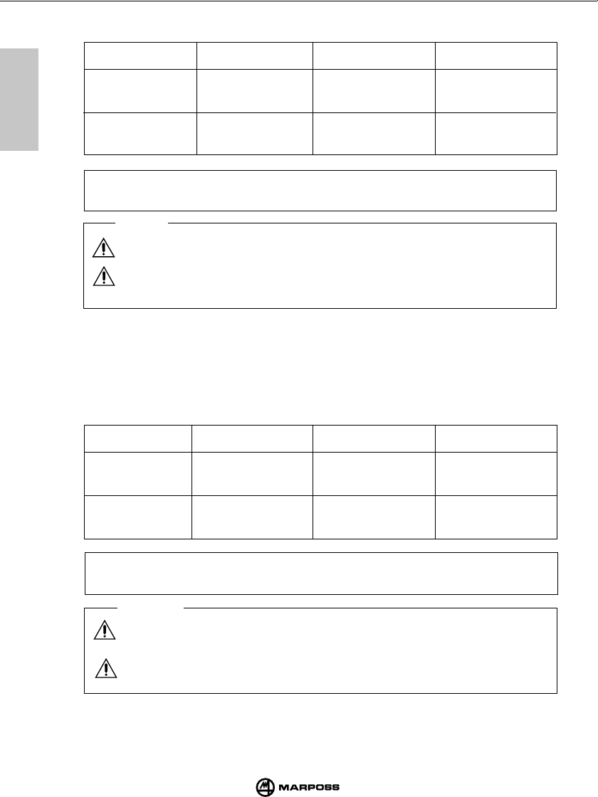
7.3 PROGRAMMING THE TRANSMITTER
Warning
Marposs declines all responsibility for damage caused by internal programming
changes carried out by unauthorised personnel.
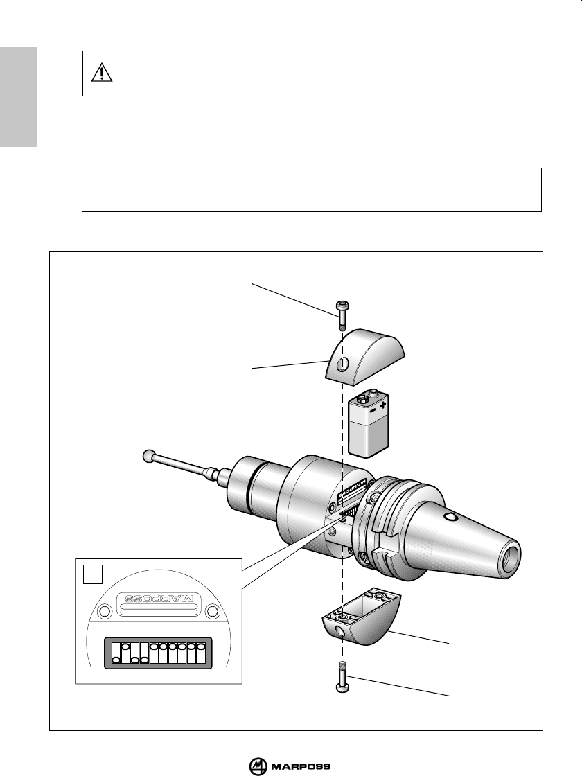
- The transmitter is programmed by setting the ON/OFF dip-switches (L).
- To reach the dip-switches (L), remove the four screws (G) and remove both the covers
(F) from the battery compartment.
Note: The transmitter is supplied with the dip-switches programmed as shown
in Figure (L).The configuration setted is also indicated on the table with
a gray box.
G
G
F
(continued ...)
F
L
12345678910
ON
OFF
7
29
SENDERMODUL EMETTEUR E86
mida
7
7.3 PROGRAMMATION DE L’EMETTEUR
Mise en garde
L’utilisateur est responsable de tout inconvénient occasionné par une variation
de la programmation interne effectuée par du personnel non agréé.
- La programmation de l’émetteur s’effectue par la programmation ON/OFF des dip-
switch (L).
- Pour accéder aux interrupteurs DIP (L), retirer les deux couvercles (F) du logement
de la batterie en dévissant les quatre vis (G).
Note: L’émetteur est livré avec la programmation que montre la Figure (interrupteur L).
(suite ...)
(segue ...)
(weiter ...)
7.3 PROGRAMMAZIONE DEL TRASMETTITORE
Avvertenza
L’utente è responsabile di ogni problema conseguente ad una variazione della
programmazione interna eseguita da personale non autorizzato.
- La programmazione del trasmettitore si esegue mediante la programmazione ON/
OFF del dip-switch (L).
- Per accedere ai dip-switch (L) rimuovere entrambi i coperchi (F) del vano batteria
togliendo le quattro viti (G).
Nota: Il trasmettitore viene fornito programmato come indicato in figura (L).
La configurazione impostata è indicata in tabella all' interno di un
riquadro grigio.
7.3 PROGRAMMIERUNG DES SENDERMODULS
Vorsicht
Der Benutzer ist für sämtliche Probleme verantwortlich, die sich infolge von
Programmänderungen durch nicht autorisiertes Personal ergeben könnten.
- Die Programmierung des Senders wird mit Hilfe der Dip-Switch (ON/OFF) (L)
vorgenommen.
- Die Dip-Switch (L) sind nach Abnahme beider Deckel (F) des Batteriefachs zugänglich;
vorher die vier Schrauben (G) abschrauben.
Hinweis: Bei Auslieferung ist das Sendermodul normalerweise wie in Abbildung
(L) programmiert. Diese programmierungen sind in den folgenden
tabellen grau unterlegt.
7
7
30
E86 TRANSMITTER TRASMETTITORE E86
mida
7.3 PROGRAMMING THE TRANSMITTER
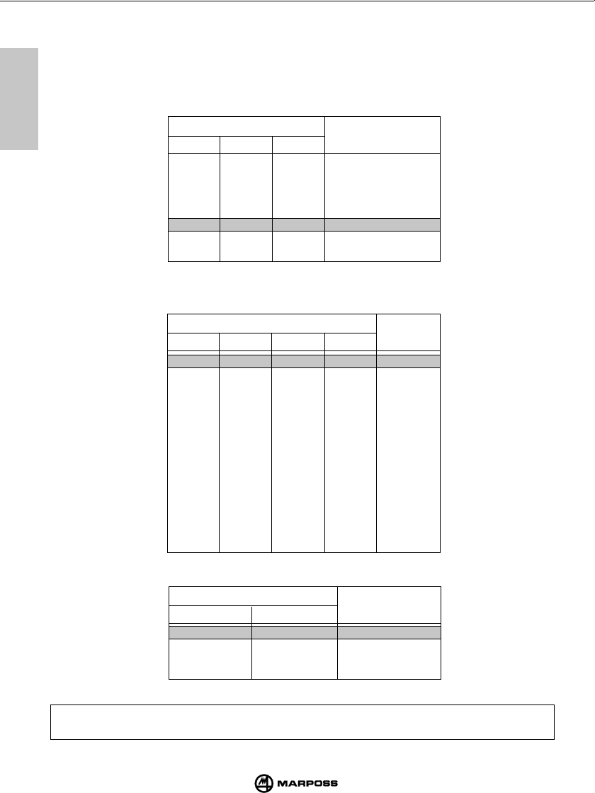
Dip-switch functions are as follows:
- Dip-switches 1, 2, 3: program the automatic transmission time-out timer as shown
in the table below (see also “Stopping transmission”).
In case of mechanical activation the dip-switches 1-2-3 must
be set in ON position
- Dip-switch 4: • OFF position,
—>
timer zero-setting after every change in probe status.
- Dip-switches 5, 6, 7, 8:
Allows the transmission channel setting according to the below
table.
- Dip-switch 9, 10: Allows the identification code setting
123
ON ON ON 4 secs.
OFF ON ON 8 secs.
ON OFF ON 17 secs.
OFF OFF ON 33 secs.
ON ON OFF 1 min. 07 secs.
OFF ON OFF 2 mins.14 secs.
ON OFF OFF 4 mins.28 secs.
OFF OFF OFF 8 mins. 57 secs.
DIP-SWITCH TIME OUT
Note:
A transmitter is identified by the working channel number and the identification code ( for eg.
12B).Verify that the transmitter and interface working channels setted match.
DIP-SWITCH
5678
ON ON ON ON 1
OFF ON ON ON 2
ON OFF ON ON 3
OFF OFF ON ON 4
ON ON OFF ON 5
OFF ON OFF ON 6
ON OFF OFF ON 7
OFF OFF OFF ON 8
ON ON ON OFF 9
OFF ON ON OFF 10
ON OFF ON OFF 11
OFF OFF ON OFF 12
ON ON OFF OFF 13
OFF ON OFF OFF 14
ON OFF OFF OFF 15
OFF OFF OFF OFF 16
CHANNEL
DIP-SWITCH
910
ON ON A
OFF ON B
ON OFF C
OFF OFF D
IDENTIFICATION
CODE
7
31
SENDERMODUL EMETTEUR E86
mida
7
DIP-SWITCH TEMPO DI
DISATTIVAZIONE
123
ON ON ON 4"
OFF ON ON 8"
ON OFF ON 17"
OFF OFF ON 33"
ON ON OFF 1' 07"
OFF ON OFF 2' 14"
ON OFF OFF 4' 28"
OFF OFF OFF 8' 57"
7.3 PROGRAMMAZIONE DEL TRASMETTITORE
La funzione dei dip-switch è la seguente:
-
Dip-switch 1-2-3:
programmazione del timer di disattivazione automatica della trasmissione,
come da seguente tabella. (vedi anche “Disattivazione della trasmissione”).
Nella versione di trasmettitore con attivazione meccanica i dip-switches 1-
2-3 devono essere in posizione ON.
- Dip-switch 4: • Posizione OFF
—>
azzeramento del timer dopo ogni variazione di stato
della sonda.
-
Dip-switch 5, 6, 7, 8:
programmazione del canale di trasmissione in base alla seguente
tabella.
- Dip-switch 9, 10: programmazione del codice di identificazione.
DIP-SWITCH
5678
ON ON ON ON 1
OFF ON ON ON 2
ON OFF ON ON 3
OFF OFF ON ON 4
ON ON OFF ON 5
OFF ON OFF ON 6
ON OFF OFF ON 7
OFF OFF OFF ON 8
ON ON ON OFF 9
OFF ON ON OFF 10
ON OFF ON OFF 11
OFF OFF ON OFF 12
ON ON OFF OFF 13
OFF ON OFF OFF 14
ON OFF OFF OFF 15
OFF OFF OFF OFF 16
CANALE
Nota: Un trasmettitore è completamente identificato dal numero di canale di lavoro e dal
codice di identificazione della frequenza ( ad esempio 12B). Assicurarsi che il canale
di lavoro impostato coincida con il canale programmato sull' unità di interfaccia.
DIP-SWITCH
910
ON ON A
OFF ON B
ON OFF C
OFF OFF D
CODICE DI
IDENTIFICAZIONE
7
7
32
E86 TRANSMITTER TRASMETTITORE E86
mida
123
ON ON ON 4 sec
OFF ON ON 8 sec
ON OFF ON 17 sec
OFF OFF ON 33 sec
ON ON OFF 1 min 07 sec
OFF ON OFF 2 min 14 sec
ON OFF OFF 4 min 28 sec
OFF OFF OFF 8 min 57 sec
ZEIT BIS ZUR
ABSCHALTUNG-
DIP-SCHALTER-NR.
KANAL
5678
ON ON ON ON 1
OFF ON ON ON 2
ON OFF ON ON 3
OFF OFF ON ON 4
ON ON OFF ON 5
OFF ON OFF ON 6
ON OFF OFF ON 7
OFF OFF OFF ON 8
ON ON ON OFF 9
OFF ON ON OFF 10
ON OFF ON OFF 11
OFF OFF ON OFF 12
ON ON OFF OFF 13
OFF ON OFF OFF 14
ON OFF OFF OFF 15
OFF OFF OFF OFF 16
DIP-SCHALTER-NR.
Hinweis: Ein Sendermodul wird durch die Nummer des Arbeitskanals und den Buchstaben für
den Identifizierungscode (z. B.12B) gekennzeichnet. Es ist sicherzustellen, daß der am
Sendermodul eingestellte Kanal mit dem an der Schnittstelleneinheit übereinstimmt.
910
ON ON A
OFF ON B
ON OFF C
OFF OFF D
DIP-SCHALTER-NR. IDENTIFIZIE-
RUNGSCODE
7.3 PROGRAMMIERUNG DES SENDERMODULS
Die Dip-Schalter haben folgende Funktionen:
- Dip-Schalter 1-2-3: Programmierung des Zeitgebers zur automatischen Abschaltung der Übertragung
gemäß folgender Tabelle (siehe auch “Abschalten der Übertragung”).
Bei
mechanischer Aktivierung müssen die Dip-Schalter in Position ON
gesetzt werden.
- Dip-Schalter 4: • OFF Position,
—>
Zurücksetzen des Zeitgebers nach jedem Statuswechsel des
Schaltmeßkopfes.
-
Dip-Schalter 5, 6, 7, 8:
Einstellen des Übertragungskanals entsprechend nachstehender Tabelle.
- Dip-Schalter 9, 10: Einstellen des Identifizierungscodes
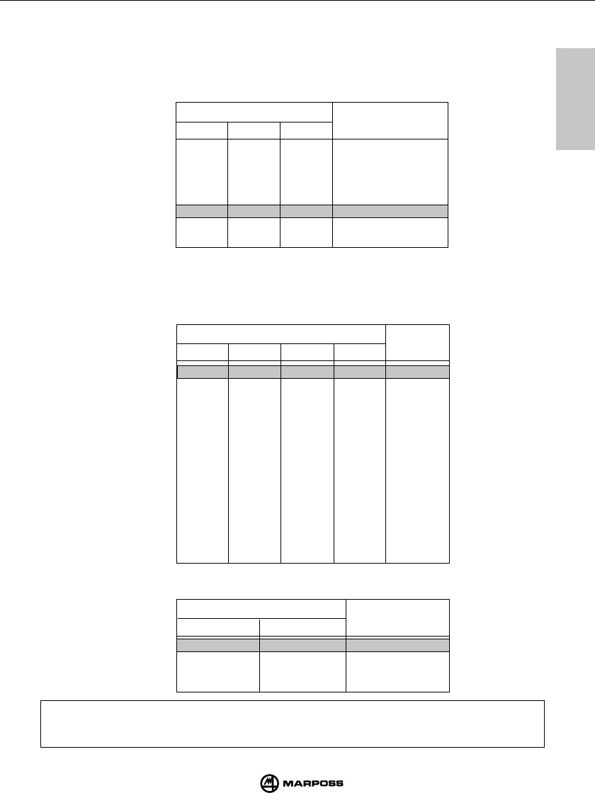
7
33
SENDERMODUL EMETTEUR E86
mida
7
DIP-SWITCH TEMPS DE
DESACTIVATION
DIP-SWITCH CHANEL
5678
ON ON ON ON 1
OFF ON ON ON 2
ON OFF ON ON 3
OFF OFF ON ON 4
ON ON OFF ON 5
OFF ON OFF ON 6
ON OFF OFF ON 7
OFF OFF OFF ON 8
ON ON ON OFF 9
OFF ON ON OFF 10
ON OFF ON OFF 11
OFF OFF ON OFF 12
ON ON OFF OFF 13
OFF ON OFF OFF 14
ON OFF OFF OFF 15
OFF OFF OFF OFF 16
DIP-SWITCH CODE
910
ON ON A
OFF ON B
ON OFF C
OFF OFF D
7.3 PROGRAMMATION DE L’EMETTEUR
Les interrupteurs DIP remplissent les fonctions suivantes:
- Interrupteur DIP 1-2-3: programmation du temporisateur de désactivation automatique de
l’émission, conformément au tableau ci-après (voir aussi
“Désactivation de l’émission).
- Dip-switch 4:
•
position OFF —> mise à zéro du temporisateur après tout changement d’état
du palpeur.
- Dip-switch 5,6,7,8: programmation du canal de transmission, conformément au tableau ci-après.
- Dip-switch 9, 10: programmation du code d'identification.
Note: Un émetteur est identifié par le numéro du canal de travail et par le code d'identification
de la fréquence (par exemple 12B). S'assurer que le canal de travail sélectionné
coïncide avec le canal programmé sur l'interface.
123
ON ON ON 4 s
OFF ON ON 8 s
ON OFF ON 17 s
OFF OFF ON 33 s
ON ON OFF 1 min 07 s
OFF ON OFF 2 min 14 s
ON OFF OFF 4 min 28 s
OFF OFF OFF 8 min 57 s
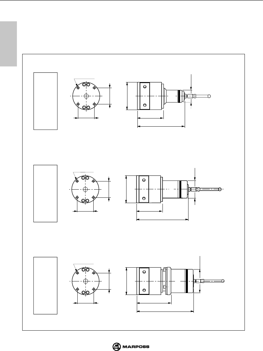
7
7
34
E86 TRANSMITTER TRASMETTITORE E86
mida
7.4 TRANSMITTER DIMENSIONS WITH PROBE
7.4 DIMENSIONI TRASMETTITORE CON SONDE
7.4 ABMESSUNGEN DER SENDERMODULE MIT ANGEBAUTEN
SCHALTMESSKÖPFEN
7.4 DIMENSIONS DES EMETTEURS AVEC PALPEURS
T25
TL25
ø 4,3 (ø 0.17")
34
(1.34")
ø60
(ø 2.36")
34
(1.34")
ø25
(ø 0.98")
62
(2.44")
WITH STANDARD PLATE
CON FLANGIA STANDARD
MIT STANDARDFLANSCH
AVEC BRIDE STANDARD
105,5
(4.15")
T36
34
(1.34")
ø 4,3 (ø 0.17")
34
(1.34")
ø60
(ø 2.36")
WITH STANDARD PLATE
CON FLANGIA STANDARD
MIT STANDARDFLANSCH
AVEC BRIDE STANDARD
62
(2.44") 117
(4.60")
WITH STANDARD PLATE
CON FLANGIA STANDARD
MIT STANDARDFLANSCH
AVEC BRIDE STANDARD
ø 4,3 (ø 0.17")
34
(1.34")
T60
34
(1.34")
ø60
(ø 2.36")
79
(3.11") 129
(5.07")
ø 51,8
(ø 1.97")
ø 35,8
(ø 1.41")
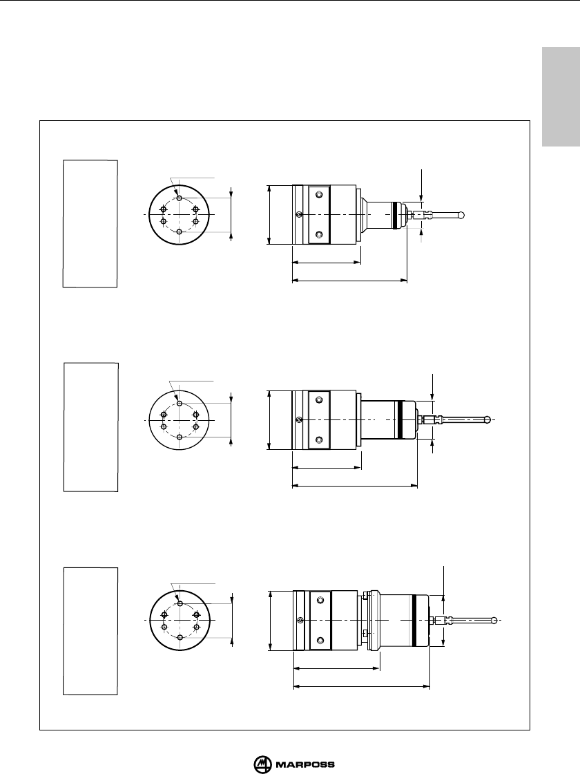
7
35
SENDERMODUL EMETTEUR E86
mida
7
T36
T25
TL25
7.4 TRANSMITTER DIMENSIONS WITH PROBE
7.4 DIMENSIONI TRASMETTITORI CON SONDE
7.4 ABMESSUNGEN DER SENDERMODULE MIT ANGEBAUTEN
SCHALTMESSKÖPFEN
7.4 DIMENSIONS DES EMETTEURS AVEC PALPEURS
WITH ADJUSTING PLATE
CON FLANGIA DI REGOLAZIONE
MIT REGULIERFLANSCH
AVEC BRIDE DE REGLAGE
ø60
(ø 2.36")
72
(2.83") 127
(5.0")
WITH ADJUSTING PLATE
CON FLANGIA DI REGOLAZIONE
MIT REGULIERFLANSCH
AVEC BRIDE DE REGLAGE
T60
89
(3.50")
ø 51,8
(ø 1.97")
139
(5.47")
ø60
(ø 2.36")
ø 35,8
(ø 1.41")
36
(1.42")
ø60
(ø 2.36")
72
(2.83")
WITH ADJUSTING PLATE
CON FLANGIA DI REGOLAZIONE
MIT REGULIERFLANSCH
AVEC BRIDE DE REGLAGE
115,5
(4.54")
ø25
(ø 0.98")
36
(1.42")
36
(1.42")
ø 4,3 (ø 0.17")
ø 4,3 (ø 0.17")
ø 4,3 (ø 0.17")
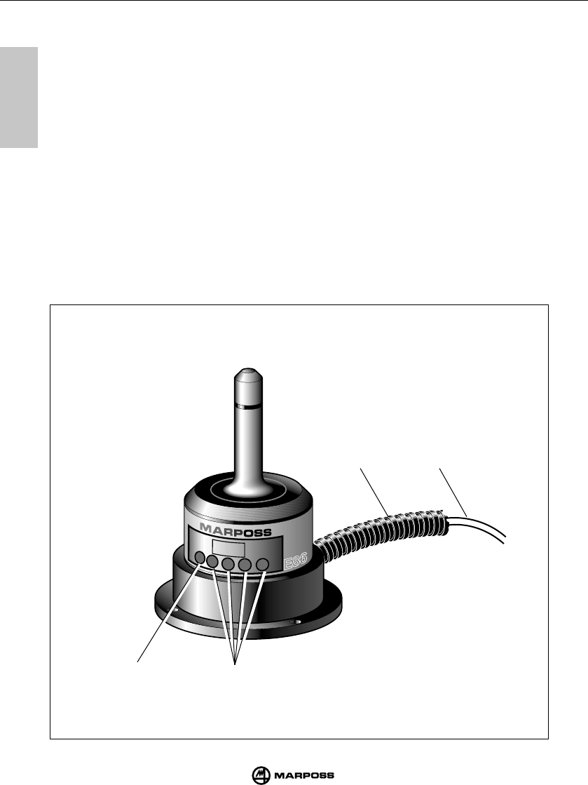
8
8
36
E86 RECEIVER RICEVITORE E86
mida
8.1 DESCRIPTION
The antenna receives the data emitted by the transmitter and send them to the E86 interface unit
connected via cable.
On the front of the antenna the following elements are visible:
A- Red LED. Lit when the system is not operating or the transmitter signal is not received.
B- One yellow LED and three green LEDs. They indicate the signal strength. During the
installation they allow to find the suitable antenna location.
C- 15 m (49.21 ft) shielded cable (5-core + shield) for connection to interface unit.
As an option, the antenna cable can be supplied with an Anaconda sheath (D) to provide full
protection in heavy duty conditions.
t
un
in
g
B
CD
A

8
8
37
EMPFÄNGERMODUL RECEPTEUR E86
mida
8.1 DESCRIZIONE
L' antenna riceve i dati emessi dal trasmettitore e li invia all’unità di interfaccia E86 alla quale va collegata
mediante il cavo in dotazione.
Sulla parte anteriore dell' antenna si trovano:
A- Un LED rosso.Acceso indica che la trasmissione non è in atto oppure che il segnale del trasmettitore
non è ricevuto.
B- Un LED giallo e tre LED verdi. Indicano l' intensità del segnale ricevuto.L’accensione dei LED facilita,
in sede di installazione, il corretto posizionamento dell' antenna.
C- Cavo schermato di lunghezza 15m per il collegamento all’unità di interfaccia E86.
Come optional è disponibile una guaina di protezione (D) tipo “anaconda sealtite” per il cavo dell' antenna
che ne assicura l’integrità anche nelle condizioni di lavoro più sfavorevoli.
8.1 BESCHREIBUNG
Das Empfängermodul (Antenne) empfängt die von Sender übertragenen Daten und leitet diese an die über
Kabel angeschlossene E86-Schnittstelleneinheit weiter.
Auf der Frontseite befinden sich folgende Elemente:
A- Rote LED: Leuchtet auf, wenn das System außer Betrieb ist, oder wenn kein Signal empfangen wird.
B- Eine gelbe LED und drei grüne LEDs. Sie zeigen die Signalstärke an. Während der Installation können
sie zur optimalen Positionierung des Empfängermoduls verwendet werden.
C- Geschirmtes Kabel (5adrig + Schirm) von 15 m Länge für den Anschluß an die Schnittstelleneinheit.
Als Option ist eine Kabelschutzhülle (D) vom Typ “Panzerschlauch” für das Empfängerkabel lieferbar,
welche das Kabel auch unter rauhesten Einsatzbedingungen schützt.
8.1 DESCRIPTION
L'antenne reçoit les données émises par l'émetteur et les envoie à l'interface E86 à laquelle elle est
branchée via le câble fourni dans le conditionnement.
Sur la partie avant de l'antenne, vous trouverez:
A- Une LED rouge. Allumée, elle indique qu'aucune transmission n'est en cours ou encore que le signal
de l'émetteur n'a pas été reçu.
B- Une LED orange et trois LEDS vertes. Elles indiquent l'intensité du signal reçu. Quand vous montez
l'antenne, servez-vous des LEDS pour positionner correctement l'antenne.
C- Cordon blindé de 15 m de longueur pour raccorder l'antenne à l'interface.
Sur demande, une gaine de protection (D) du type “anaconda” peut être fournie pour le câble du récepteur
afin d’en assurer la protection même dans les conditions de travail les plus hostiles.
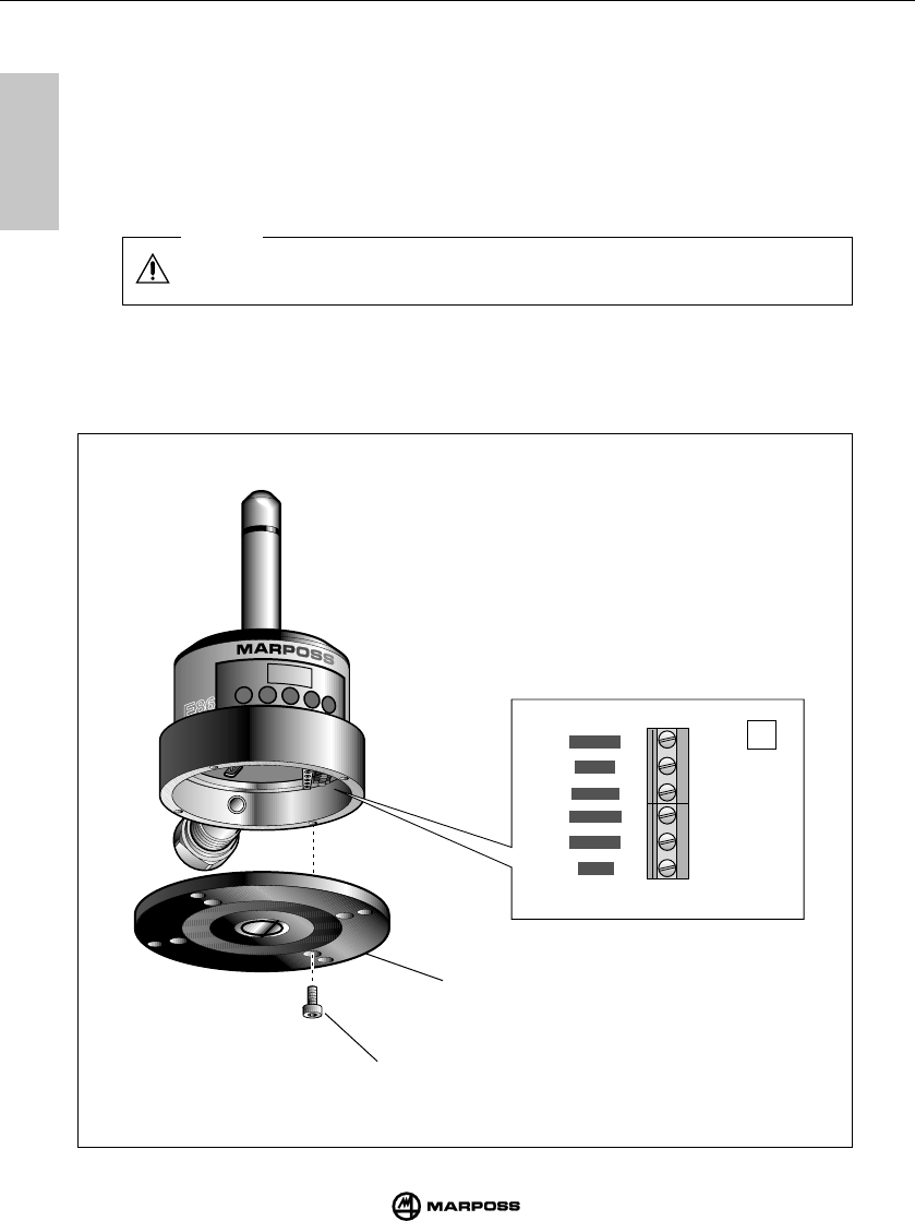
8
8
38
E86 RECEIVER RICEVITORE E86
mida
8.2 CONNECTING UP THE ANTENNA
When connecting ensure that the wire and terminal coding match.
The color of each terminal on the electrical board (C) has a matching colored wire.
Connect the antenna to the E86 interface unit as shown in the connection diagram (see chapter
9.5 "Connecting up the interface unit".
The cable is connected to the terminal block on the bottom of the electrical board. To disconnect
up the antenna proceed as follow:
• Unscrew the screw (A)
• Remove the plate (B)
A
tun
ing
RED
SHIELD
VIOLET
WHITE
BLUE
GREEN
C
B
Caution
8
8
39
EMPFÄNGERMODUL RECEPTEUR E86
mida
8.2 COLLEGAMENTO DELL' ANTENNA
L' antenna va collegata alla morsettiera dell’unità di interfaccia E86; vedere schema di collega-
mento al cap. 9.5 "Collegamenti all'unità di interfaccia".
L' antenna viene fornita con il cavo collegato mediante una morsettiera interna; per accedervi
operare nel seguente modo:
• Svitare, le viti (A).
• Estrarre il coperchio (B).
Avvertenza
In fase di collegamento rispettate la corrispondenza colore filo-morsetto.
Per ogni morsetto è indicato sul circuito stampato (C) il colore del filo corrispondente.
8.2 ANSCHLUSS DES EMPFÄNGERMODULS
Das Empfängermodul wird an die Klemmenleiste der E86-Schnittstelleneinheit angeschlossen.
Siehe dazu das Anschlußschema in Kap. 9.5 "Anschlüsse der Schnittstelleneinheit".
Das Empfängermodul wird mit einem Kabel von 15 m Länge, das über eine interne Klemmenleiste
angeschlossen wird, geliefert. Für den Anschluß ist wie folgt vorzugehen:
• Die Schrauben (A) lösen.
• Die Scheibe (B) herausnehmen.
Vorsicht
Beim Anschluß auf Übereinstimmung der Farben der Adern und der Klemmen achten.
Für jede Klemme ist auf der Leiterplatte (C) die Farbe der entsprechenden Ader
angegeben.
8.2 RACCORDEMENT DU RÉCEPTEUR
L'antenne doit être reliée au bornier de l'interface E86; voir le schéma de la section 9.5 "Connexions
à l'interface".
L'antenne est livrée avec un câble relié à un bornier interne; pour y accéder, procéder comme suit:
• Desserrer les vis (A);
• Enlever le couvercle (B).
Mise en garde
Pour les connexions, respecter la correspondance couleur fil-borne. Pour chaque borne,
vous trouverez la couleur du fil correspondant sur le circuit imprimé (C).

8
8
40
E86 RECEIVER RICEVITORE E86
mida
8.3 FITTING THE ANTENNA TO THE MACHINE
• The antenna can be fixed provisionally with a magnetic base in order to locate the correct
position and verify that the signal emitted by the transmitter is received during the probing
system movement.
• For permanent installation the antenna can be fixed by using the four screw on issue.
8.3 ANBAU DES EMPFÄNGERMODULS
• Das Empfängermodul wird provisorisch mit der Magnetbasis befestigt, um die optimale
Befestigungsposition zu finden und um den Empfang des vom Sender übertragenen Signals
beim Verfahren des Schaltsystems sicherzustellen.
• Die entgültige Befestigung des Empfängermoduls erfolgt über die vier mitgelieferten Schrauben.
8.3 MONTAGGIO DELL' ANTENNA
• L' antenna può essere fissata provvisoriamente mediante la base magnetica per definire la
posizione di fissaggio più idonea e verificare che il segnale emesso dal trasmettitore venga
ricevuto durante gli spostamenti del sistema di tastatura.
• Per il montaggio permanente fissare l' antenna con le quattro viti in dotazione.
8.3 MONTAGE DE L'ANTENNE
• L'antenne peut être fixée provisoirement par la base magnétique pour définir la meilleure position
de fixation et vérifier si le signal émis par l'émetteur est bien reçu pendant les déplacements du
palpeur.
• Pour le montage définitif, fixer l'antenne avec les quatre vis fournies dans le conditionnement.
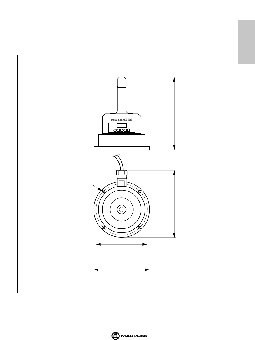
8
8
41
EMPFÄNGERMODUL RECEPTEUR E86
mida
8.4 ANTENNA DIMENSIONS
8.4 DIMENSIONI D' INGOMBRO ANTENNA
8.4 ABMESSUNGEN DER EMPFÄNGERMODULS
8.4 DIMENSIONS DU RECEPTEUR
tuning
(4.72")
120
ø 4 (4 x)
ø 0.16 (4 x)
100
(3.93")
ø 85
(ø 3.34")
ø 92
(ø 3.62")
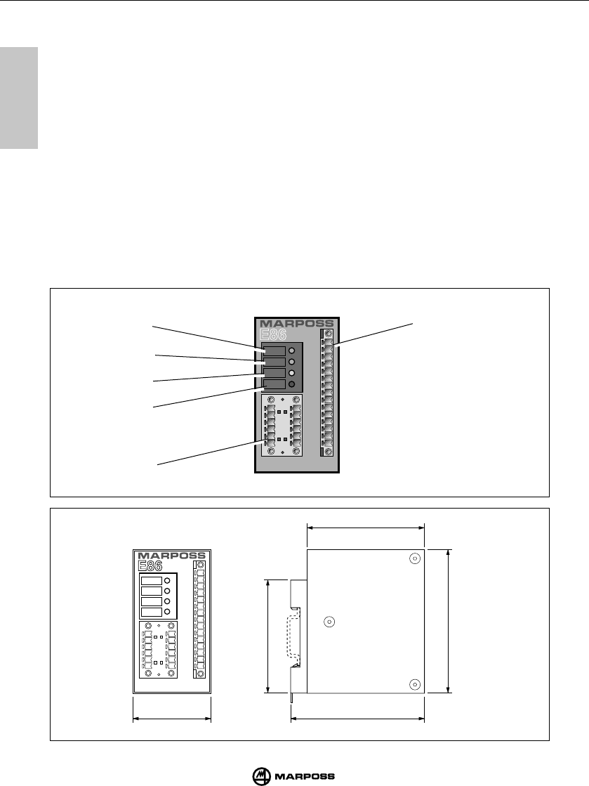
42
E86 INTERFACE UNIT UNITÁ DI INTERFACCIA E86
mida
9
9
9.1 INTERFACE UNIT FRONT PANEL
A-"power" (green) LED : indicates that the interface unit is powered up.
B-"probe" (green) LED : indicates probe status. When lit, indicates that the probe
stylus is deflected. When unlit, indicates that the probe
stylus is in the rest position.
C -"battery low"
(yellow)
LED : indicates that the battery life is low or that the battery is
discharged (see also the LOW BAT output signal -
“Connecting up the interface unit”).
D-"error" (red) LED : indicates an error condition. It lights up to indicate that the
probe is outside the range of the transmission field or that
the system is not activated (see also Error output signal -
“Connecting up the interface unit”).
E -terminal block : I/O connection to the machine CNC.
F
- terminal block : antenna connection
power
probe
low
battery
error
A
B
C
D
F
E
power
probe
low
battery
error
(1.91")
48,5
(3.15")
80
(3.39")
86
(2.67")
67,8
(2.78")
70

43
SCHNITTSTELLENEINHEIT E86 UNITE D’INTERFACE E86
mida
9
9
9.1 PANNELLO FRONTALE UNITÀ DI INTERFACCIA
A- LED “power” (verde) : acceso con tensione di alimentazione presente.
B- LED “probe” (verde) : indica lo stato della sonda. Acceso quando il braccetto della son-
da è deflesso. Spento quando il braccetto della sonda è a riposo.
C- LED “low battery” (giallo) : acceso indica che la batteria è quasi completamente scarica.
(vedi anche segnale di uscita LOW BAT “Collegamenti all’unità di
interfaccia”).
D- LED “error” (rosso) : indica una condizione di errore. Si accende quando la trasmissione
non è attivata, o quando la sonda è fuori dalla portata del campo di
trasmissione (vedi anche segnale di uscita ERROR “Collegamenti
all’unità di interfaccia”).
E- MORSETTIERA : Permette i collegamenti elettrici al CNC
F- MORSETTIERA : Per il collegamento di una o due antenne.
9.1 FRONTTAFEL DER SCHNITTSTELLENEINHEIT
A-“power”-LED (grün) : Betriebsanzeige, wenn Versorgungsspannung anliegt.
B-“probe”-LED (grün) : Statusanzeige für Schaltmeßkopf ist an, wenn der Tasterarm
ausgelenkt ist, aus, wenn der Tasterarm in Ruhestellung ist.
C-“low battery”-LED (gelb) : Leuchtet die Anzeige auf, ist die Batterie leer bzw. zu schwach.
Die Batterie muß ausgewechselt werden (siehe auch Ausgangs-
signal LOW BAT “Anschlüß der Schnittstelleneinheit”).
D-“error”-LED (rot) : Die Fehleranzeige leuchtet, wenn das Sendermodul nicht aktiviert
ist, wenn die Übertragungsstrecke zwischen Sender und
Empfänger unterbrochen ist oder wenn der Schaltmeßkopf mit
seinem Sendermodul außerhalb des Empfangsbereichs liegt
(siehe auch Ausgangssignal ERROR “Anschlüß der
Schnittstelleneinheit”).
E- KLEMMEN : Elektrischer Anschluß an die CNC-Steuerung
F- KLEMMEN : Anschluß eines oder zweier Empfängermodule
9.1 PANNEAU AVANT DE L’INTERFACE
A- LED “power” (verte) : allumée si l’appareil est sous tension.
B- LED “probe” (verte) : indique l’état du palpeur.
Elle est allumée si le bras du palpeur est activé. Elle est éteinte
si le bras du palpeur est en position de repos.
C - LED “low battery” (orange)
: Allumée, elle signale que la batterie est à plat ou insuffisante. Il
faut remplacer la batterie (voir aussi le signal de sortie
LOW BAT - “Connexions à l'interface”).
D - LED “error” (rouge) : indique une condition d’erreur. Elle s’allume si le palpeur n’est
pas activé, ou si le palpeur est en dehors de la zone d’émission
(voir aussi signal de sortie ERROR - “Connexions à l’interface”).
E- BORNIER : Permet les raccordements électriques à la CNC
F- BORNIER : Pour le raccordement d'un ou de deux récepteurs
9.2 INTERFACE UNIT DIMENSIONS
9.2 DIMENSIONI UNITA' D' INTERFACCIA
9.2 ABMESSUNGEN DER SCHNITTSTELLENEINHEIT
9.2 DIMENSIONS DE L'INTERFACE

44
E86 INTERFACE UNIT UNITÁ DI INTERFACCIA E86
mida
9
9
9.3 E86 INTERFACE UNIT TECHNICAL FEATURES
Power supply : 24 VDC, unstabilised (18-35 V)
300 mA with two receivers connected up
Input signals : Opto-insulated inputs, 24 V 10 mA.
SEL 0 - SEL 1 :
Operating channel or activation code selection (see Chapt. 9.4)
START : Transmission activation
Note: SINK or SOURCE connections can be used for input signal connections.
For SINK connection, connect the “COM” to the “+24V” terminal.
For SOURCE connection, connect the “COM” to the “0V” terminal.
Output signals
: Solid state relay contact (SSR), 50 V - 40 mA.
ERROR : Communication error (probe off, probe outside transmission field, transmitter
battery completely discharged).
PROBE 1 : This is the output signal for the status of the probe currently in use (Probe
status = seated position or deflected).
PROBE 2 / SKIP
: Additional output signal for the probe currently in use; can be programmed as
a probe status signal (probe in seated position or deflected) or a SKIP signal
(pulse) according to the dip-switch 3 position (See “Programming the interface
unit”).
LOW BAT : Low battery level signal indicated by the “Low Battery” LED on the panel (by
using an akaline battery the system runs for about 5 hours after the Low
Battery Signal).
9.3 CARATTERISTICHE TECNICHE INTERFACCIA E86
Alimentazione : 24 VDC non stabilizzata (18-35 V)
300 mA max. (con due antenne collegate)
Segnali ingresso
:
Ingressi optoisolati 24 V - 10 mA
SEL 0 - SEL 1 : Selezione canale di lavoro o codice di attivazione (vedi Cap. 9.4)
START : Attivazione della trasmissione
Nota: Il collegamento dei segnali di ingresso può essere di tipo SINK (collegare
“COM” alla “+24V”) oppure di tipo SOURCE (collegare “COM” alla “0V”).
Segnali di uscita:
Contatti Relè a Stato Solido (SSR) 50V - 40 mA
ERROR : Errore di comunicazione (sonda non attivata o fuori dalla portata del campo
di trasmissione, batteria trasmettitore completamente scarica).
PROBE 1 : Segnale relativo allo stato della sonda in uso (sonda a riposo o sonda
deflessa).
PROBE 2/SKIP : Segnale addizionale relativo allo stato della sonda in uso; può essere
programmato come segnale di stato sonda (a riposo o deflessa) o SKIP
(impulso) a seconda del posizionamento del dip-switch 3 dell' unità di
interfaccia.
LOW BAT :
Segnale di batteria quasi scarica (utilizzando una batteria alcalina il funziona-
mento residuo del sistema in condizizone di Low Battery è pari a circa 5 ore).

45
SCHNITTSTELLENEINHEIT E86 UNITE D’INTERFACE E86
mida
9
9
9.3 ANSCHLUSS DER SCHNITTSTELLENEINHEIT
Versorgung : 24 VDC nicht stabilisiert (18-35 V)
max. 300 mA (bei zwei Empfängermodulen)
Eingangssignale:
optoisolierte Eingänge 24V - 10 mA
SEL 0 - SEL 1
:
Anwahl des Arbeitskanal (Frequenz) oder des Identifizierungscodes (siehe Kap. 9.4)
START : Aktivierung der Übertragung
Hinweis:
Der Anschluß der Eingangssignale kann entweder vom Typ SINK sein
(“COM” an “+24V” anschließen) oder vom Typ SOURCE (“COM” an “OV”
anschließen).
Ausgangssignale
: Solid-State-Relaiskontakte (SSR) 50 V - 40 mA
ERROR : Übertragungsfehler (Schaltmeßkopf nicht aktiviert, außerhalb des
Übertragungsbereichs oder Senderbatterie völlig leer)
PROBE1 : Statussignal für den verwendeten Schaltmeßkopf (in Ruhestellung
oder ausgelenkt)
PROBE2/SKIP : Zusätzliches Statussignal für den verwendeten Schaltmeßkopf; kann als
Meßkopf Statussignal (in Ruhestellung oder ausgelenkt) oder SKIP (Impuls)
entsprechend der Stellung des Dip-Schalters 3 der Schnitt-stelleneinheit
programmiert werden.
LOW BAT : Signal für die Anzeige “Batterie schwach” (bei Verwendung einer Alkali-
batterie ist die Lebensdauer im Low Battery Betrieb noch ca. 5 Stunden).
9.3 UNITE D’INTERFACE
Alimentation : 24 VCC non stabilisé (18-35 V)
300 mA avec deux récepteurs connectés
Signaux d’entrée :
Entrées optocouplées 24 V / 10 mA
SEL 0 - SEL 1 :
Sélection du canal de travail ou du code d’activation (voir Chapitre 9.4)
START : Activation de la transmission
Nota: La liaison des signaux d’entrée peut être du type SINK (relier le “COM ” au
“+24V”), ou du type SOURCE (relier le “COM” au “0 V”)
Signaux de sortie
:
Contact relai à l'état solide (SSR) 50 V - 40 mA.
ERROR : Erreur de communication (palpeur non activé, palpeur en dehors de la
zone d’émission, batterie émetteur à plat).
PROBE 1 : Signal de sortie relatif à l’état du palpeur en cours d’utilisation (palpeur au
repos ou palpeur activé).
PROBE 2/SKIP : Signal additionnel de sortie relatif au palpeur en cours d’utilisation: il peut
être programmé comme signal d’état du palpeur (au repos ou activé) ou
SKIP (impulsion) suivant le positionnement de l'interrupteur DIP 3 -
“Programmation de l’interface”.
LOW BAT : Signal de batterie à plat (la LED “low battery” s'allume) (en utilisant une
batterie alcaline, le systéme, en condition de "Low Battery" fonctionne
pour une periode de 5 heures).
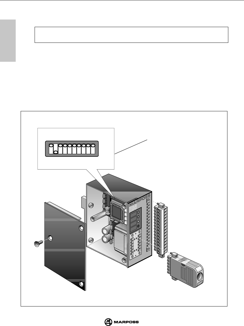
46
E86 INTERFACE UNIT UNITÁ DI INTERFACCIA E86
mida
9
9
1 2 3 4 5 6 7 8
power
probe
low
battery
error
1 2 3 4 5 6 7 8 9 10 11 12 13 14 15
12345678910
ON
OFF
9.4 PROGRAMMING THE INTERFACE UNIT
The interface unit is programmed by setting the ON/OFF dip-switches (H).
Note: The interface is supplied with the dip-switches programmed as shown
in Figure.
The configuration set is indicated on the table with a gray box.
To program the interface unit, proceed as follows:
- Switch off the interface unit.
- Remove the three retaining screws and remove the cover.
H
(continued ...)

47
SCHNITTSTELLENEINHEIT E86 UNITE D’INTERFACE E86
mida
9
9
9.4 PROGRAMMAZIONE DELL’UNITÀ DI INTERFACCIA
Il modo di funzionamento del sistema E86 è programmabile mediante il posizionamento ON/
OFF del dip-switch (H).
Nota: L’unità di interfaccia viene fornita programmata come indicato in figura
(H).La configurazione impostata è indicata in tabella all'interno di un riquadro
grigio.
Per la programmazione dell’unità di interfaccia, procedere nel seguente modo (riferimenti in
figura):
- Spegnere l’unità di interfaccia.
- Rimuovere il pannello laterale togliendo le tre viti di fissaggio.
(segue ...)
(weiter ...)
(suite ...)
9.4 PROGRAMMATION DE L’INTERFACE
Le mode de fonctionnement de l’interface est programmable en positionnant sur ON/OFF les
interrupteurs DIP (H).
Note: L'interface est fournie avec la programmation que montre la Figure -
Interrupteur DIP (H).
Pour la programmation de l’interface, procéder comme suit (voir la figure):
- l’interface doit être hors tension;
- ôter le panneau latéral en dévissant les trois vis de fixation.
9.4
PROGRAMMIERUNG DER SCHNITTSTELLENEINHEIT
Die Betriebsart der Schnittstelleneinheit ist über den Dip-Schalter (H) programmierbar (ON/ OFF).
Hinwe
is:
Bei Auslieferung ist das Sendermodul normalerweise wie in Abbildung (L)
programmiert. Diese Programmierungen sind in den folgenden Tabellen grau
unterlegt.
Zur Programmierung der Schnittstelleneinheit ist wie folgt vorzugehen (siehe Abbildung):
-
Die Schnittstelleneinheit muß ausgeschaltet sein.
-
Bei Schnittstelleneinheit im Gehäuse die seitliche Abdeckung abzunehmen; dazu die drei
Befestigungsschrauben lösen.
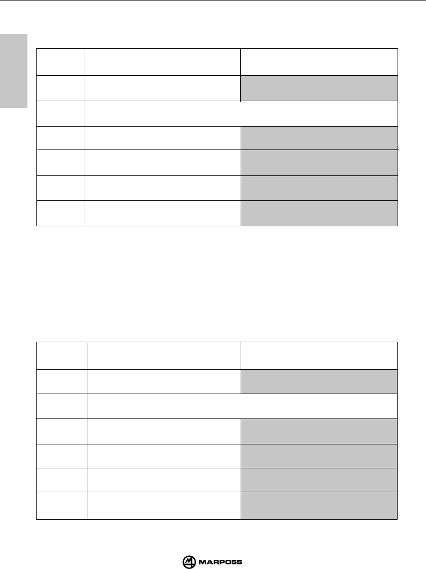
48
E86 INTERFACE UNIT UNITÁ DI INTERFACCIA E86
mida
9
9
SEL0 -SEL1= transmission channel
(1-16) and activation code (A-D) selec-
tion
PROBE 2 output = SKIP (pulse at every
probe status change).
PROBE 1 output contact =
N.C. (normally closed).
PROBE 2 output contact =
N.C. (normally closed).
LOW BATTERY output contact =
N.C. (normally closed).
SEL0 -SEL1= selezione canale di tra-
smissione (1-16) e codice di attivazione
(A-D)
Uscita PROBE 2 = SKIP (impulso
ad ogni cambio di stato della sonda)
Contatto di uscita PROBE 1 =
N.C. (normale chiuso)
Contatto di uscita PROBE 2 =
N.C. (normale chiuso)
Contatto di uscita LOW BATTERY =
N.C. (normale chiuso)
SEL0 -SEL1= selezione codice di attiva-
zione (A-D)
Uscita PROBE 2 = PROBE (Stato sonda:
contatto aperto o contatto chiuso)
Contatto di uscita PROBE 1 =
N.O. (normale aperto)
Contatto di uscita PROBE 2 =
N.O. (normale aperto)
Contatto di uscita LOW BATTERY =
N.O. (normale aperto)
SEL0 -SEL1= activation code (A-D)
selection
PROBE 2 output = PROBE (Probe
status:triggered or in rest position)
PROBE 1 output contact =
N.O. (normally open).
PROBE 2 output contact =
N.O. (normally open).
LOW BATTERY output contact =
N.O. (normally open).
9.4 PROGRAMMING THE INTERFACE UNIT
Program the unit on the dip-switches (H) using the table below to obtain the operating mode
required.
(segue ...)
OFF ON
DIP SWITCH
(H)
1
4
3
1
5
OFF
2
DIP SWITCH
(H)
(continued ...)
6
9.4 PROGRAMMAZIONE DELL'UNITÀ DI INTERFACCIA
Mediante il dip-switch (H) eseguire la programmazione del modo di funzionamento, secondo la
tabella:
6
5
3
2
4
ON
Switch non utilizzato:
per il corretto funzionamento deve essere in posizione OFF
Switch not used:
for correct operation, set to OFF position
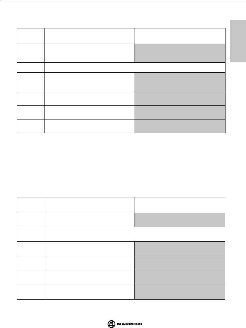
49
SCHNITTSTELLENEINHEIT E86 UNITE D’INTERFACE E86
mida
9
9
SEL0 - SEL1= sélection du canal de
transmission (1-16) et du code d’activation (A-
D)
Sortie PROBE 2 = SKIP (impulsion à
chaque changement d'état de la sonde)
Contact de sortie PROBE 1 =
N.C. (N.F. normalement fermé)
Contact de sortie PROBE 2 = N.C.
(N.F.normalement fermé)
Contact de sortie LOW BATTERY = N.C.
(N.F. normalement fermé)
SEL0 - SEL1= sélection du code
d’activation (A-D)
Sortie PROBE 2 = PROBE (Etat de la
sonde: contact ouvert ou contact fermé)
Contact de sortie PROBE 1 =
N.O. (normalement ouvert)
Contact de sortie PROBE 2 =
N.O. (normalement ouvert)
Contact de sortie LOW BATTERY =
N.O. (normalement ouvert)
(suite ...)
9.4 PROGRAMMIERUNG DER SCHNITTSTELLENEINHEIT
Mit dem Dip-Schalter (H) die Programmierung der Betriebsart gemäß folgender Tabelle vornehmen:
(weiter ...)
OFF ON
DIP SWITCH
(H)
6
5
4
3
2
1
9.4 PROGRAMMATION DE L’INTERFACE
Effectuer la programmation du mode de fonctionnement au moyen de l'interrupteur DIP (H),
suivant le tableau ci-après:
SEL0-SEL1 = Anwahl des Arbeitskanals
(Frequenz) (1-16) und des
Identifizierungscodes (A-D)
Ausgang 2 Schaltmeßkopf (PROBE 2)
Status des Schaltmeßkopfes als Impuls.
Ausgang 1 (PROBE1) = Schaltmeßkopf
als Öffner
Ausgang 2 (PROBE2) = Schaltmeßkopf
als Öffner.
Ausgangskontakt BATTERIE SCHWACH
(LOW BATT) als Öffner.
4
3
1
5
OFF ON
2
6
SCHALTER-NR.
(H)
Schalter nicht benutzt
SEL0-SEL1 = Anwahl des Arbeitskanals
Identifizierungscodes (A-D)
Ausgang 2 Schaltmeßkopf (PROBE 2)
Status des Schaltmeßkopfes als
kontinuierliches Signal.
Ausgang 1 (PROBE1) = Schaltmeßkopf
als Schließer
Ausgang 2 (PROBE2) = Schaltmeßkopf
als Schließer.
Ausgangskontakt BATTERIE SCHWACH
(LOW BATT) als Schliesser.
Switch non utilisé:
pour un fonctionnement correct, il doit être sur la position OFF
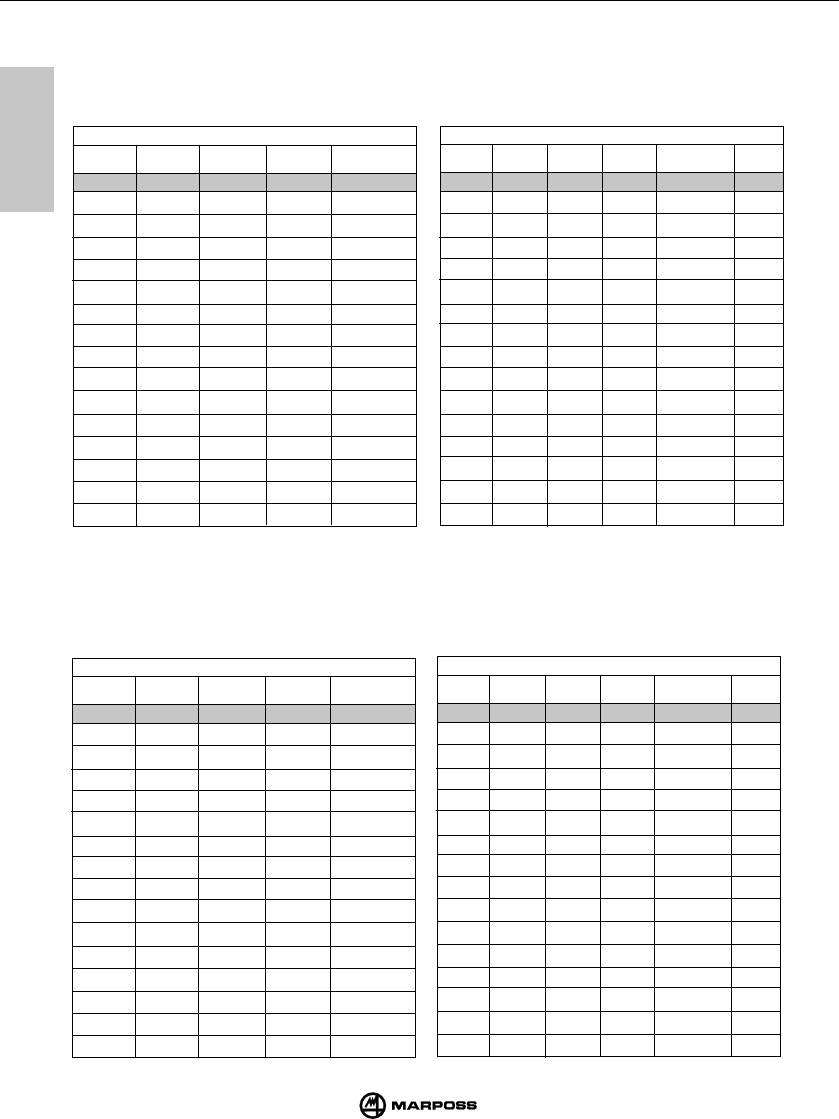
50
E86 INTERFACE UNIT UNITÁ DI INTERFACCIA E86
mida
9
9
9.4 PROGRAMMAZIONE DELL'UNITÀ DI INTERFACCIA
Se lo switch 1 è posto in On è possibile programmare il canale di funzionamento come indicato nella
tabella sottostante mediante gli switch 7-8-9-10. Se lo switch 1 è posto in OFF la programmazione
del canale è effettuata mediante gli switch 7 e 8 ed i due ingressi SEL0 e SEL1. In questo caso gli
switch 9 e 10 sono disabilitati pertanto possono essere posti in una qualunque configurazione.
9.4 PROGRAMMING THE INTERFACE UNIT
If switch 1 is in the On position, the operating channel can be programmed as indicated in the ta-
ble below using switches 7-8-9-10. If switch 1 is in the OFF position, the channel is programmed
using switches 7 and 8 and the two inputs SEL0 and SEL1. In this case, switches 9 and 10 are
disabled, therefore, they may be in any configuration.
ON ON ON ON 1
OFF ON ON ON 2
ON OFF ON ON 3
OFF OFF ON ON 4
ON ON OFF ON 5
OFF ON OFF ON 6
ON OFF OFF ON 7
OFF OFF OFF ON 8
ON ON ON OFF 9
OFF ON ON OFF 10
ON OFF ON OFF 11
OFF OFF ON OFF 12
ON ON OFF OFF 13
OFF ON OFF OFF 14
ON OFF OFF OFF 15
OFF OFF OFF OFF 16
78 910
CHANNEL
SWITCH No.1 = ON
ON ON ON ON 1
OFF ON ON ON 2
ON OFF ON ON 3
OFF OFF ON ON 4
ON ON OFF ON 5
OFF ON OFF ON 6
ON OFF OFF ON 7
OFF OFF OFF ON 8
ON ON ON OFF 9
OFF ON ON OFF 10
ON OFF ON OFF 11
OFF OFF ON OFF 12
ON ON OFF OFF 13
OFF ON OFF OFF 14
ON OFF OFF OFF 15
OFF OFF OFF OFF 16
7 8 9 10 CANALE
SWITCH No.1 = ON
7 8 SEL0 SEL1
CHANNEL CODE
ON ON 0 0 1 A
ON ON 1 0 5 B
ON ON 0 1 9 C
ON ON 1 1 13 D
OFF ON 0 0 2 A
OFF ON 1 0 6 B
OFF ON 0 1 10 C
OFF ON 1 1 14 D
ON OFF 0 0 3 A
ON OFF 1 0 7 B
ON OFF 0 1 11 C
ON OFF 1 1 15 D
OFF OFF 0 0 4 A
OFF OFF 1 0 8 B
OFF OFF 0 1 12 C
OFF OFF 1 1 16 D
SWITCH No.1 = OFF
7 8 SEL0 SEL1 CANALE COD.
ON ON 0 0 1 A
ON ON 1 0 5 B
ON ON 0 1 9 C
ON ON 1 1 13 D
OFF ON 0 0 2 A
OFF ON 1 0 6 B
OFF ON 0 1 10 C
OFF ON 1 1 14 D
ON OFF 0 0 3 A
ON OFF 1 0 7 B
ON OFF 0 1 11 C
ON OFF 1 1 15 D
OFF OFF 0 0 4 A
OFF OFF 1 0 8 B
OFF OFF 0 1 12 C
OFF OFF 1 1 16 D
SWITCH No.1 = OFF
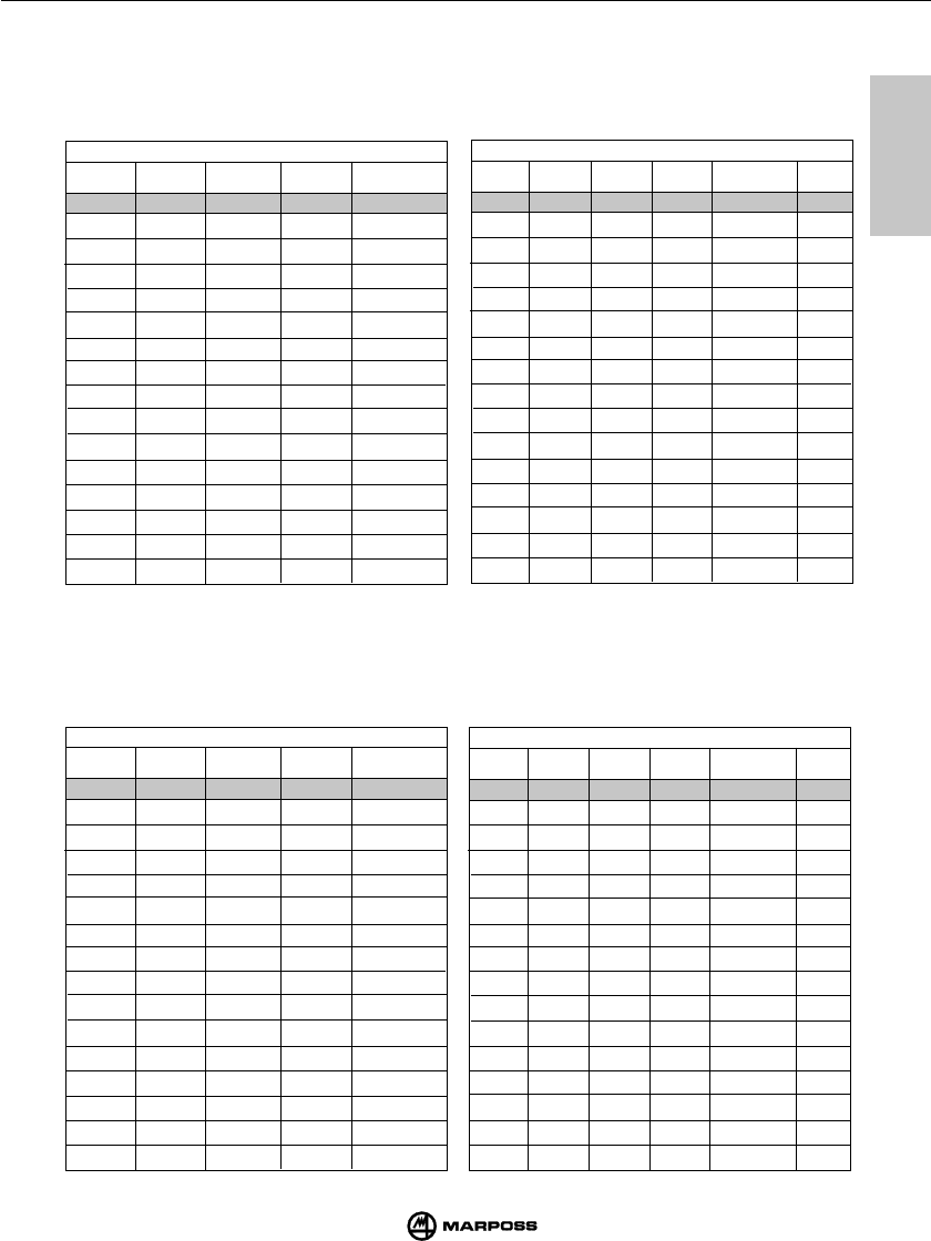
51
SCHNITTSTELLENEINHEIT E86 UNITE D’INTERFACE E86
mida
9
9
9.4 PROGRAMMATION DE L’INTERFACE
Si le commutateur 1 est sur On, vous pouvez programmer le canal de fonctionnement comme l’indique
le tableau ci-dessous avec les commutateurs 7-8-9-10. Si le commutateur 1 est sur OFF, le canal se
programme avec les commutateurs 7 et 8 et les deux entrées SEL0 et SEL1. Dans ce cas, les
commutateurs 9 et 10 sont désactivés et peuvent donc être placés dans n’importe quelle configuration.
9.4 PROGRAMMIERUNG DER SCHNITTSTELLENEINHEIT
Wenn der Dip-Schalter 1 in Position ON ist, wird der Arbeitskanal (Frequenz) entsprechend der
folgenden Tabelle über die Dip-Schalter 7-8-9-10 eingestellt. Wenn der Dip-Schalter 1 in Position
OFF ist, wird der Arbeitskanal (Frequenz) über die Dip-Schalter 7 und 8 und die beiden Eingänge
SEL0 und SEL1. In diesem Fall ist die Stellung der Dip-Schalter 9 und 10 wirkungslos.
ON ON ON ON 1
OFF ON ON ON 2
ON OFF ON ON 3
OFF OFF ON ON 4
ON ON OFF ON 5
OFF ON OFF ON 6
ON OFF OFF ON 7
OFF OFF OFF ON 8
ON ON ON OFF 9
OFF ON ON OFF 10
ON OFF ON OFF 11
OFF OFF ON OFF 12
ON ON OFF OFF 13
OFF ON OFF OFF 14
ON OFF OFF OFF 15
OFF OFF OFF OFF 16
7 8 9 10 KANAL
Dip-Schalter Nr.1 = ON
ON ON ON ON 1
OFF ON ON ON 2
ON OFF ON ON 3
OFF OFF ON ON 4
ON ON OFF ON 5
OFF ON OFF ON 6
ON OFF OFF ON 7
OFF OFF OFF ON 8
ON ON ON OFF 9
OFF ON ON OFF 10
ON OFF ON OFF 11
OFF OFF ON OFF 12
ON ON OFF OFF 13
OFF ON OFF OFF 14
ON OFF OFF OFF 15
OFF OFF OFF OFF 16
7 8 9 10 CHANEL
SWITCH No.1 = ON
7 8 SEL0 SEL1 KANAL
ID.CODE
ON ON 0 0 1 A
ON ON 1 0 5 B
ON ON 0 1 9 C
ON ON 1 1 13 D
OFF ON 0 0 2 A
OFF ON 1 0 6 B
OFF ON 0 1 10 C
OFF ON 1 1 14 D
ON OFF 0 0 3 A
ON OFF 1 0 7 B
ON OFF 0 1 11 C
ON OFF 1 1 15 D
OFF OFF 0 0 4 A
OFF OFF 1 0 8 B
OFF OFF 0 1 12 C
OFF OFF 1 1 16 D
SWITCH No.1 = OFF
7 8 SEL0 SEL1
CHANEL
CODE
ON ON 0 0 1 A
ON ON 1 0 5 B
ON ON 0 1 9 C
ON ON 1 1 13 D
OFF ON 0 0 2 A
OFF ON 1 0 6 B
OFF ON 0 1 10 C
OFF ON 1 1 14 D
ON OFF 0 0 3 A
ON OFF 1 0 7 B
ON OFF 0 1 11 C
ON OFF 1 1 15 D
OFF OFF 0 0 4 A
OFF OFF 1 0 8 B
OFF OFF 0 1 12 C
OFF OFF 1 1 16 D
SWITCH No.1 = OFF
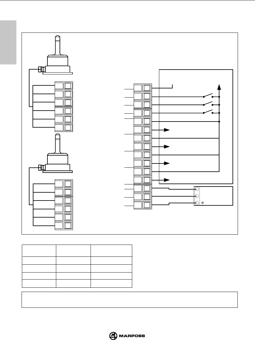
52
E86 INTERFACE UNIT UNITÁ DI INTERFACCIA E86
mida
9
9
OPEN/0V OPEN/0V A
24 V OPEN/0V B
OPEN/0V 24 V C
24 V 24 V D
SEL 0 SEL 1 ID. CODE
CONDITION WITH SOURCE CONNECTION
(continued ...)
Note:
If the transmission channel is programmed using inputs SEL 0 and SEL 1 (switch No.1
interface = OFF) they must switch at least 200 ms before the START signal.
9.5 CONNECTING UP THE INTERFACE UNIT
The interface unit card has a terminal block for connections. Connect the wires to the
screw terminals using the connection diagram.
12456
3
RED
SHIELD
VIOLET
12456
3
124
356
78910 11 12 13 14 15
24 V
0 V
POWER
SUPPLY
UNIT
CNC MACHINE CONTROL
SSR SSR SSR SSR
COM
SEL 1
SEL 0
START
PROBE
STATUS 1
PROBE
STATUS 2/SKIP
LOW BATTERY
ERROR
GROUND
0 V
+ 24 V DC
ANTENNA 2
+ 24 V
ERROR
LOW BATTERY
PROBE
STATUS 2/SKIP
0 V
ANTENNA 1
PROBE STATUS 1
GREEN
BLUE
WHITE
GREEN
BLUE
WHITE
VIOLET
SHIELD
RED
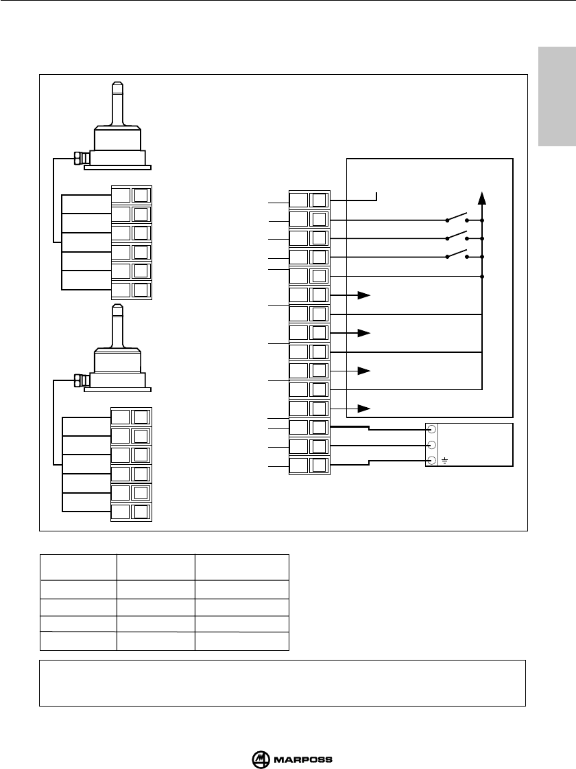
53
SCHNITTSTELLENEINHEIT E86 UNITE D’INTERFACE E86
mida
9
9
9.5 COLLEGAMENTI ALL’UNITÀ DI INTERFACCIA
Sulla scheda dell’unità è presente la morsettiera di collegamento; le connessioni
vengono effettuate mediante connettori con attacco a vite .
(segue ...)
OPEN/0V OPEN/0V A
24 V OPEN/0V B
OPEN/0V 24 V C
24 V 24 V D
SEL 0 SEL 1
CONDIZIONE CON COLLEGAMENTO TIPO SOURCE
CODICE DI
IDENTI-
FICAZIONE
Nota: Se la programmazione del canale di trasmissione è effettuata mediante gli ingressi SEL 0 e SEL
1(switch No.1 interfaccia = OFF) la loro commutazione deve avvenire almeno 200 ms prima del segnale
di START.
12456
312456
3
124
356
78910 11 12 13 14 15
24 V
0 V
SSR SSR SSR SSR
COM
SEL 1
SEL 0
START
TERRA
0 V
+ 24 V DC
ANTENNA 2
ANTENNA 1
+ 24 V
0 V
UNITÀ DI
ALIMEN.
STATO SONDA 1
STATO SONDA 2
SKIP
BATTERIA
SCARICA
ERRORE ERRORE
BATTERIA SCARICA
STATO SONDA 2 SKIP
STATO SONDA 1
CNC CONTROLLO MACCHINA
ROSSO
SCHERMO
VIOLA
BIANCO
BLU
VERDE
ROSSO
SCHERMO
VIOLA
BIANCO
BLU
VERDE
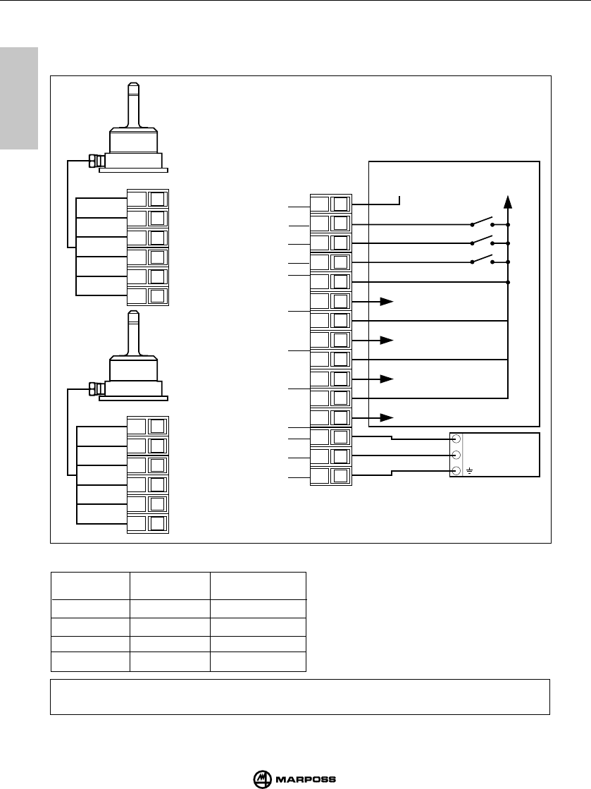
54
E86 INTERFACE UNIT UNITÁ DI INTERFACCIA E86
mida
9
9
OFFEN/0V OFFEN/0V A
24 V OFFEN/0V B
OFFEN/0V 24 V C
24 V 24 V D
SEL 0 SEL 1
SENDERMODUL ANWAHL IN SOURCE
(weiter ...)
IDENT.-CODE
Hinweis: Wenn die Anwahl des Übertragungskanals (Frequenz) über die Eingänge SEL0 und SEL1 (Dip-Schalter
1 der Schnittstelleneinheit = OFF) erfolgt, muß die Anwahl mindestens 200 ms vor dem START erfolgen.
9.5 ANSCHLUSS DER SCHNITTSTELLENEINHEIT
Auf der Platine der Schnittstelleneinheit befindet sich die Anschlußklemmenleiste; die Anschlüsse
werden durch Schraubklemmen vorgenommen; siehe Anschlußplan.
12456
312456
3
124
356
78910 11 12 13 14 15
24 V
0 V
SSR SSR SSR SSR
COM
SEL 1
SEL 0
START
SCHUTZLEITER
0 V
+ 24 V DC
+ 24 V
0 V
MASCHINEN STEUERUNG
FEHLER
BATTERIE SCHWACH
MESSKOPF AUSGANG 1
STATUS
MESSKOPF AUSGANG 2
STATUS oder SKIP
STROMVER-
SORGUNG
FEHLER
BATTERIE SCHWACH
MESSKOPF AUSGANG 2
STATUS oder SKIP
MESSKOPF AUSGANG 1
STATUS
GRÜN
BLAU
WEISS
VIOLET
SCHIRM
ROT
GRÜN
BLAU
WEISS
VIOLET
SCHIRM
ROT
EMPFÄNGER
1
EMPFÄNGER
2
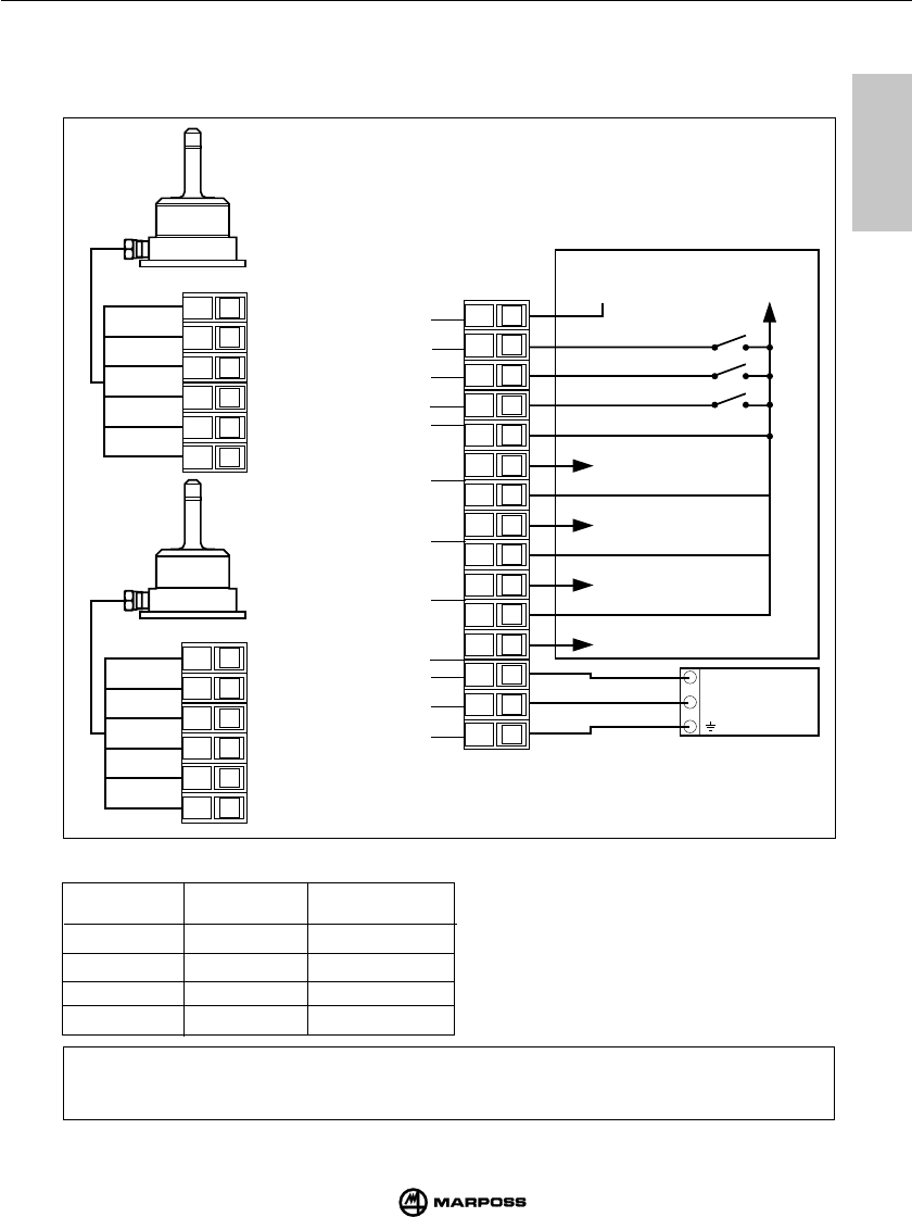
55
SCHNITTSTELLENEINHEIT E86 UNITE D’INTERFACE E86
mida
9
9
9.5 CONNEXIONS A L'INTERFACE
Sur la carte d'interface se trouve le bornier des connexions; les bornes sont à vis; voir schéma des
connexions.
Nota:
Si la programmation du canal de transmission utilise les entrées SEL 0 et SEL 1 (switch
no.1 interface = OFF), leur commutation doit se produire 200 ms au moins avant le signal
de marche (START).
OPEN/0V OPEN/0V A
24 V OPEN/0V B
OPEN/0V 24 V C
24 V 24 V D
SEL 0 SEL 1 CODE
CONNEXION TYPE SOURCE
(suite ...)
12456
312456
3
124
356
78910 11 12 13 14 15
24 V
0 V
SSR SSR SSR SSR
COM
SEL 1
SEL 0
START
TERRE
0 V
+ 24 V DC
+ 24 V
0V
ANTENNE 1
ANTENNE 2
VERT
ROUGE
BLINDAGE
CONTROLE MACHINE CN
UNITE
D'ALIMENT.
ETAT SONDE 1
ETAT SONDE 2
SKIP
BAT.
DECHARGEE
ERREUR
ETAT SONDE 1
ETAT SONDE 2
SKIP
BAT.
DECHARGEE
ERREUR
VIOLET
BLANC
BLEU
VERT
BLEU
BLANC
VIOLET
BLINDAGE
ROUGE
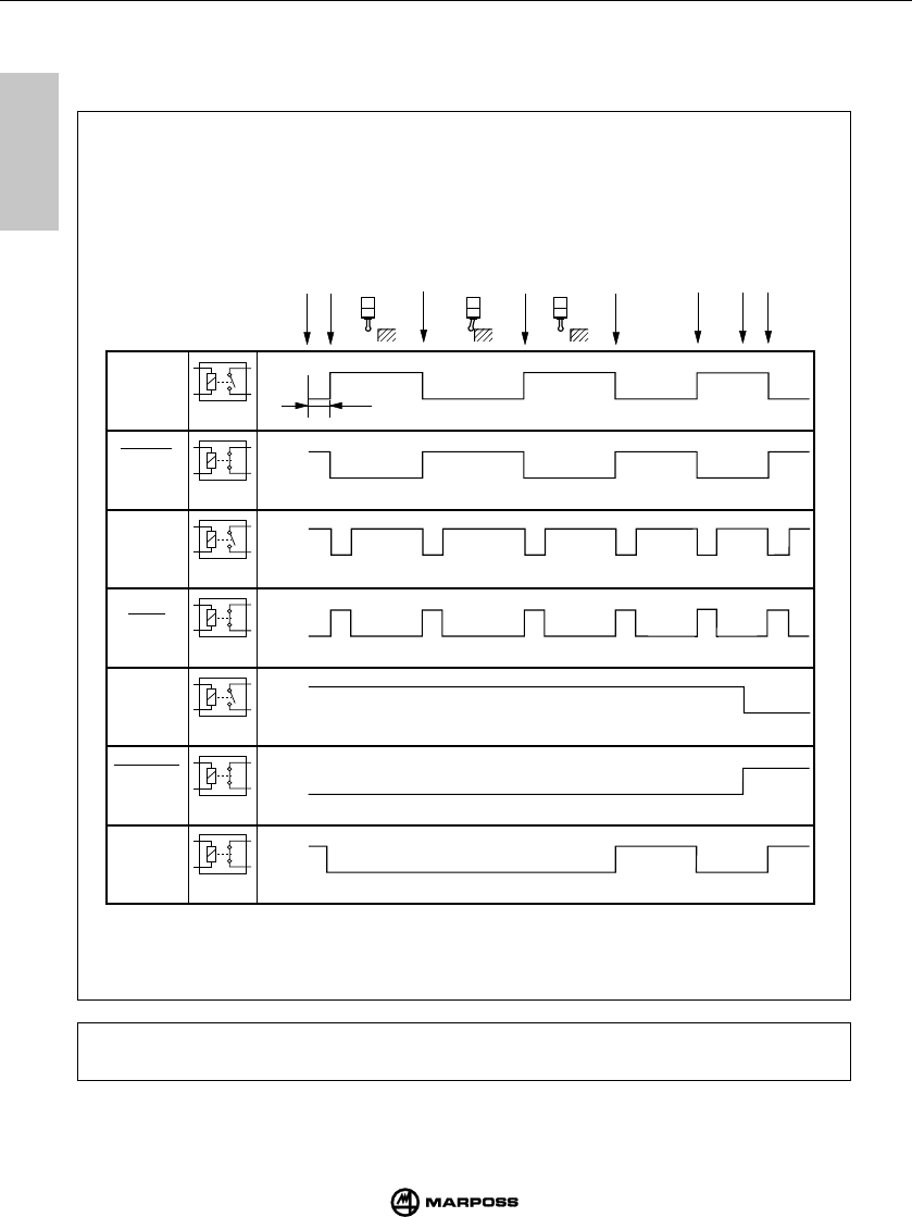
56
E86 INTERFACE UNIT UNITÁ DI INTERFACCIA E86
mida
9
9
9.5 CONNECTING UP THE INTERFACE UNIT
I/O diagram of interface unit E86
Open
Close
Probe
status
N.O.
Probe
status
Skip
Low
battery
Error
Skip
Low
battery
Solid
state
relay
Start
Probe activated
At rest
Probe trigger
Deflected
Probe reseat
At rest
Error
Error clear
Low battery
Probe off
Open
Close
Open
Close
Open
Close
Open
Close
Open
Close
Open
Close
N.C.
N.O.
N.C.
N.O.
N.C.
N.C.
E86
Signal
1 s
Note: The activation time, tipically lower than 1 sec. can increase up to about 3 secs. if the
working area is disturbed by electromagnetic interferences.
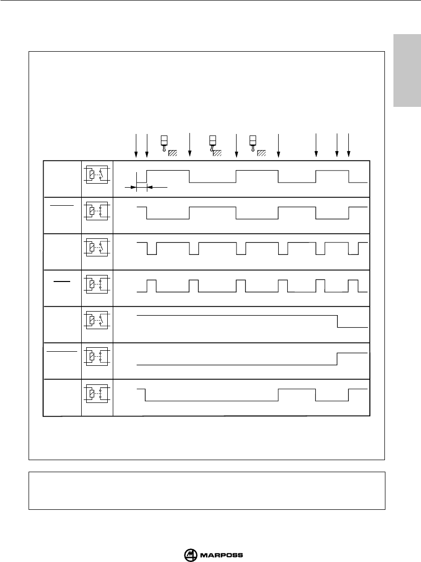
57
SCHNITTSTELLENEINHEIT E86 UNITE D’INTERFACE E86
mida
9
9
9.5 COLLEGAMENTI ALL’UNITÀ DI INTERFACCIA
Diagramma I/O unità di interfaccia E86
aperto
chiuso
Stato
sonda
N.O.
Stato
sonda
Skip
Batteria
scarica
Errore
Skip
Batteria
scarica
Relè
stato
solido
Start
Sonda attivata
A riposo
Apertura contatto
Deflessa
Chiusura contatto
A riposo
Errore
Errore eliminato
Batteria scarica
Sonda disattivata
aperto
chiuso
aperto
chiuso
aperto
chiuso
aperto
chiuso
aperto
chiuso
aperto
chiuso
N.C.
N.O.
N.C.
N.O.
N.C.
N.C.
Segnali
E86
1 s
Nota:
In alcuni ambienti di lavoro particolarmente disturbati da interferenze elettromagne-
tiche il tempo necessario per attivare la trasmissione può essere superiore ad 1
secondo (max 3).
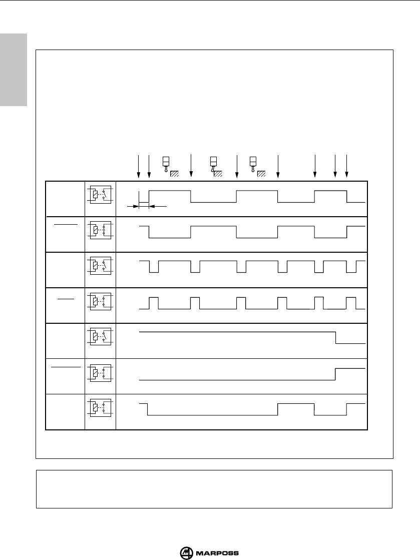
58
E86 INTERFACE UNIT UNITÁ DI INTERFACCIA E86
mida
9
9
Hinweise: Die Aktivierungszeit, die typischerweise weniger als 1 s ist, kann sich bis auf ca.
3 s erhöhen, wenn sich weitere elektromagnetische Interferenzen im
Arbeitsbereich auftreten.
9.5 ANSCHLUSS DER SCHNITTSTELLENEINHEIT
Ablaufdiagramm
offen
geschlossen
MESSKOPF
STATUS
Schließer
Skip
Batterie
schwach
Fehler
Skip
Meßkopf
status
Start
Schaltmeßkopf bereit
Ruhestellung
Schaltsignal
ausgelenkt
Schaltmeßkopf wieder bereit
Ruhestellung
Fehleer im System
Fehler weg
Batterie schwach
Schaltmeßsystem aus
offen
offen
offen
offen
offen
offen
Öffner geschlossen
geschlossen
geschlossen
geschlossen
geschlossen
geschlossen
Schließer
Schließer
Öffner
Öffner
Öffner
MESSKOPF
STATUS
Batterie
schwach
E86
Signale
1 s
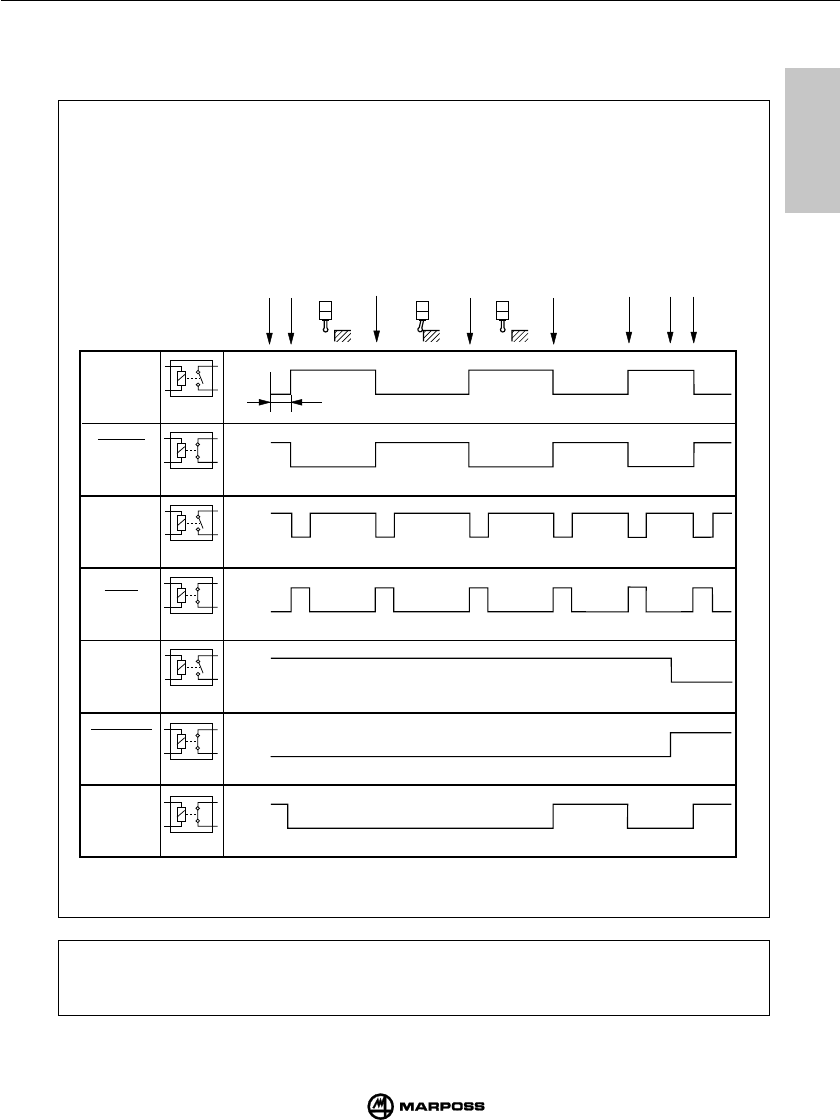
59
SCHNITTSTELLENEINHEIT E86 UNITE D’INTERFACE E86
mida
9
9
9.5 CONNEXIONS A L'INTERFACE
Diagramme des E/S de l’nterface E86
Note: Si l'environnement de travail est sujet à de fortes interférences électromagnétiques,
le temps nécessaire pour activer la transmission peut être supérieur à 1 seconde
(max 3).
ouvert
fermé
ETAT
SONDE
N.O.
Skip
Batterie
déchargée
Erreur
Skip
Relai
état
solide
Start
Sonde activée
En repos
Contact ouvert
Fléchie
Contact fermé
En repos
Erreur
Elimination erreur
Batterie déchargée
Sonde désactivée
ouvert
ouvert
ouvert
ouvert
ouvert
ouvert
N.F. fermé
fermé
fermé
fermé
fermé
fermé
N.O.
N.O.
N.F.
N.F.
N.F.
ETAT
SONDE
Batterie
déchargée
Signaux
E86
1 s
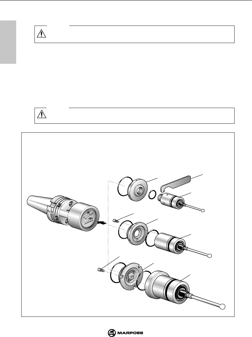
10
10
60
ASSEMBLING THE PROBE TO THE TRANSMITTER MONTAGGIO SONDA-TRASMETTITORE
mida
T25/TL25
T36
A1
A
B1 B
C1 C
T60
10.1 ASSEMBLING THE PROBE TO THE TRANSMITTER
To fit/remove the probe to/from the transmitter, follow the instructions below.
Caution
When fitting the probe to the transmitter, ensure that the seal rings are in good condition and correctly
positioned.
PROBE T25/TL25
- Tighten the holder (A) to the transmitter using the special spanner supplied (A1).
- Using the special spanner supplied screw the probe to the holder (A).
PROBE T36
- Fix the probe to the holder (B) using the screws (B1).
- Using the special spanner supplied screw the holder (B) to the transmitter.
PROBE T60
- Fix the probe to the holder (C) using the screws (C1).
- Using the special spanner supplied screw the holder (C) to the transmitter.
Caution
When you have completed the above operations, align the system.(see page 66)
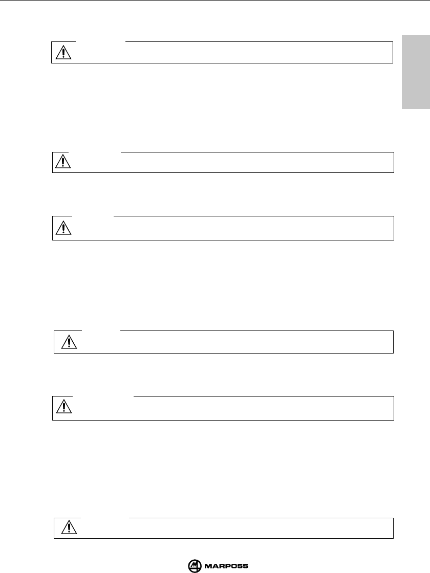
10
10
61
AN- UND ABBAU DER SCHALTMESSKÖPFE AM / VOM SENDERMODUL MONTAGE PALPEUR - EMETTEUR
mida
10.1 MONTAGGIO SONDA-TRASMETTITORE
Per il montaggio o lo smontaggio della sonda dal trasmettitore procedere nel seguente modo:
Avvertenza
In fase di montaggio della sonda è bene assicurarsi che gli anelli di tenuta siano in ottime condizioni
e posizionati correttamente nella loro sede.
SONDA T25/TL25
- avvitare la flangia (A) al trasmettitore, mediante la chiave apposita (A1).
- avvitare la sonda, alla flangia (A) utilizzando la chiave in dotazione.
SONDA T36
- fissare la sonda alla flangia (B) tramite le viti (B1);
- Avvitare la flangia (B) al trasmettitore utilizzando la chiave in dotazione
SONDA T60
- fissare la sonda alla flangia (C) tramite le viti (C1);
- Avvitare la flangia (C) al trasmettitore utilizzando la chiave in dotazione
Avvertenza
Ad operazione ultimata occorre eseguire l’allineamento del sistema.
10.1 AN- UND ABBAU DER SCHALTMESSKÖPFE AM / VOM SENDERMODUL
Für den An- und Abbau der Schaltmeßköpfe ist wie folgt vorzugehen:
Vorsicht
Bei der Montage des Schaltmeßkopfes muß sichergestellt werden, daß die Dichtringe in guten Zustand
sind und korrekt sitzen.
SCHALTMESSKOPF T25/TL25
- Den Flansch (A) am Sender mit dem geeigneten Schlüssel festschrauben (A1).
- Den Schaltmeßkopf am Flansch (A) mit dem mitgelieferten Schlüssel befestigen.
SCHALTMESSKOPF T36
- Den Schaltmeßkof am Flansch (B) über die Schrauben (B1) befestigen.
- Den Flansch (B) mit dem Schlüssel im Lieferumfang festschrauben.
SCHALTMESSKOPF T60
- Den Schaltmeßkopf mit den Schrauben (C1) am Flansch (C) befestigen.
- Den Flansch (C) am Sender mit dem Schlüssel im Lieferumfang befestigen.
Vorsicht
Nach der Montage muß das System ausgerichtet werden.
10. 1 MONTAGE PALPEUR-EMETTEUR
Pour monter et démonter le palpeur de l'émetteur, procéder comme suit:
Avertissement
Au moment de monter le palpeur, s'assurer que les bagues d'étanchéité sont en parfaites conditions
et les positionner corrrectement dans leur logement.
SONDE T25/TL25
- visser la bride (A) à l'émetteur avec la clé (A1);
- visser la sonde à la bride (A) avec la clé fournie dans le conditionnement.
SONDE T36
- fixer la sonde à la bride (B) avec les vis (B1);
- visser la bride (B) à l'émetteur avec la clé fournie dans le conditionnement;
SONDE T60
- fixer la sonde à la bride (C) avec les vis (C1);
- visser la bride (C) à l'émetteur avec la clé fournie dans le coditionnement.
Mise en garde
Quand l'opération est terminée, effectuer la mise au point du système.
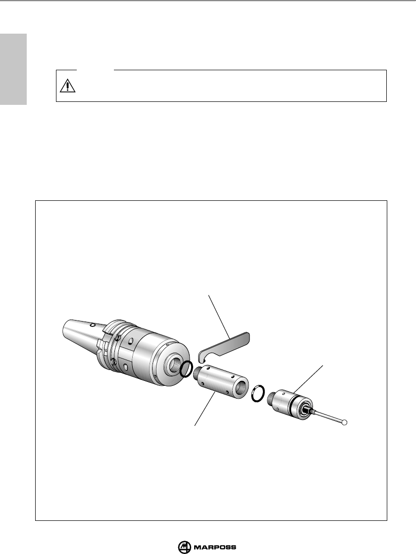
11
11
62
INSERTING PROBE EXTENSIONS (OPTIONAL) INSERIMENTO PROLUNGHE PER SONDE (OPTIONAL)
mida
A1
A2
T25/TL25
11.1 INSERTING PROBE EXTENSIONS (OPTIONAL)
The probe extension is fitted between the probe and the transmitter; the purpose of the extension
is to increase the measuring depth of the system.
To fit an extension, proceed as follows:
Caution
When fitting an extension, ensure that the seal rings are in good condition and correctly
positioned.
• T25/TL25 probe extension
- Using the spanner supplied (A1), remove the probe from the transmitter.
- Fit the extension (A2) complete with seal rings between the probe and the transmitter.
- Using the spanner provided (A1), tighten the probe/extension/transmitter assembly.
(continued ...)
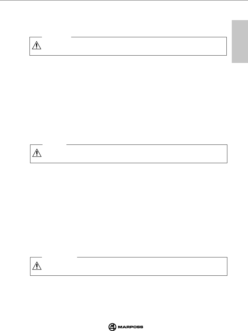
11
11
63
EINBAU VON VERLÄNGERUNGEN FÜR SCHALTMESSKÖPFE MONTAGE DES RALLONGES POUR PALPEURS (EN OPTION)
mida
(segue ...)
(weiter ...)
(suite ...)
11.1 INSERIMENTO PROLUNGHE PER SONDE (OPTIONAL)
La prolunga viene inserita tra sonda e trasmettitore per aumentare la profondità di misura del
sistema. Per l'inserimento delle prolunghe procedere nel seguente modo.
Avvertenze
In fase di inserimento prolunga è bene assicurarsi che gli anelli di tenuta siano in ottime
condizioni e posizionati correttamente nella loro sede.
• Prolunga per sonda T25/TL25
- Rimuovere la sonda dal trasmettitore con l'apposita chiave (A1) in dotazione.
- Interporre tra sonda e trasmettitore la prolunga (A2) con relativi anelli di tenuta.
- Serrare il gruppo con l'ausilio della chiave (A1) in dotazione.
11.1 EINBAU VON VERLÄNGERUNGEN FÜR SCHALTMESSKÖPFE
Eine Verlängerung wird zwischen Schaltmeßkopf und Sendermodul eingesetzt, um in größere
Meßtiefen eindringen zu können, ohne den Tasterarm länger als nötig zu machen.
Für den Einbau einer Verlängerung für den Schaltmeßkopf ist wie folgt bei den verschiedenen
Köpfen vorzugehen:
Vorsicht
Beim Einbau der Verlängerung sind die Dichtringe auf einwandfreien Zustand und
korrekten Sitz zu prüfen.
• Verlängerung für Schaltmeßkopf T25/TL25
- Den Meßkopf mittels des mitgelieferten Schlüssels (A1) vom Adapterring am Sendermodul
abschrauben.
- Die Verlängerung (A2) mit Dichtungsring an den Adapterring auf dem Sendermodul schrauben.
- Den Kopf mit Dichtungsring auf die Verlängerung schrauben.
- Die Verlängerung und den Kopf mittels des mitgelieferten Schlüssel (A1) festziehen.
11.1 MONTAGE DES RALLONGES POUR PALPEURS (EN OPTION)
La rallonge est montée entre le palpeur et l’émetteur pour augmenter la profondeur de mesure du
système. Pour le montage des rallonges, procéder comme suit:
Mise en garde
Au moment du montage de la rallonge, il est important de s’assurer que les bagues
d’étanchéité sont en bon état et positionnées correctement dans leurs logements.
• Rallonge pour palpeur T25/TL25
- Retirer le palpeur de l’émetteur à l’aide de la clé fournie avec l’appareil (A1).
- Interposer la rallonge (A2) entre le palpeur et l’émetteur avec les bagues d’étanchéité
correspondantes.
- Serrer le groupe à l’aide de la clé (A1) fournie avec l’appareil.
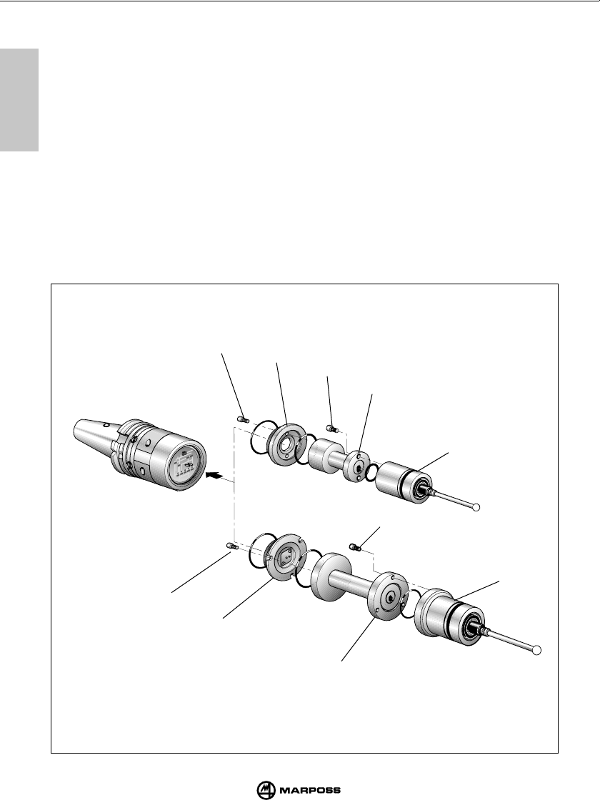
11
11
64
INSERTING PROBE EXTENSIONS (OPTIONAL) INSERIMENTO PROLUNGHE PER SONDE (OPTIONAL)
mida
11.1 INSERTING PROBE EXTENSIONS (OPTIONAL)
• T36 probe extension
- Unscrew the holder (B) from the transmitter.
- Unscrew the screws (B1) and remove the probe from the holder (B).
- Fix the extension (B2) to the holder (B) using the screws (B1).
- Fix the extension/holder assembly to the transmitter using the spanner
- Fix the probe to the extension using the screws (B3).
• T60 probe extension
- Unscrew the holder (C) from the transmitter.
- Unscrew the screws (C1) and remove the probe from the holder (C).
- Fix the extension (C2) to the holder (C) using the screws (C1).
- Screw the extension/holder assembly to the transmitter using the spanner
- Fix the probe to the extension using the screws (C3).
B
B2
B3
B1
C1
C2
C3
C
T60
T36

11
11
65
EINBAU VON VERLÄNGERUNGEN FÜR SCHALTMESSKÖPFE MONTAGE DES RALLONGES POUR PALPEURS (EN OPTION)
mida
11.1 INSERIMENTO PROLUNGHE PER SONDE (OPTIONAL)
• Prolunga per sonda T36
- Svitare la flangia (B) dal trasmettitore.
- Rimuovere la sonda dalla flangia (B) togliendo le viti (B1).
- Fissare la prolunga (B2) alla flangia (B) tramite le viti (B1).
- Avvitare il gruppo flangia/prolunga,al trasmettitore con la chiave in dotazione
- Fissare la sonda alla prolunga tramite le viti (B3).
• Prolunga per sonda T60
- Svitare la flangia (C) dal trasmettitore.
- Rimuovere la sonda dalla flangia (C) togliendo le viti (C1).
- Fissare la prolunga (C2) alla flangia (C) tramite le viti (C1).
- Avvitare il gruppo flangia/prolunga,al trasmettitore con la chiave in dotazione
- Fissare la sonda alla prolunga tramite le viti (C3).
11.1 EINBAU VON VERLÄNGERUNGEN FÜR SCHALTMESSKÖPFE
• Verlängerung für Schaltmeßkopf T36
- Den Flansch (B) vom Sender lösen.
- Den Schaltmeßkopf vom Flansch (B) nach Entfernen der Schrauben (B1) lösen.
- Die Verlängerung (B2) am Flansch (B) über die Schrauben (B1) befestigen.
- Die Baugruppe Flansch/Verlängerungen mit dem Schlüssel am Sender befestigen.
- Den Schaltmeßkopf an der Verlängerung mit den Schrauben (B3) befestigen.
• Verlängerung für Schaltmeßkopf T60
- Den Flansch (C) vom Sender lösen.
- Den Schaltmeßkopf vom Flansch (C) nach Entfernen der Schrauben (C1) lösen.
- Die Verlängerung (C2) am Flansch (C) über die Schrauben (C1) befestigen.
- Die Baugruppe Flansch/Verlängerungen mit dem Schlüssel am Sender befestigen.
- Den Schaltmeßkopf an der Verlängerung mit den Schrauben (C3) befestigen.
11.1 MONTAGE DES RALLONGES POUR PALPEURS (EN OPTION)
• Rallonge pour Palpeur T36
- Dévisser la bride (B) de l'émetteur.
- Desserrer les vis (B1) pour libérer la sonde de la bride (B).
- Fixer la rallonge (B2) à la bride (B) avec les vis (B1).
- Visser le groupe bride/rallonge à l'émetteur avec la clé fournie dans le conditionnement.
- Fixer la sonde à la rallonge avec les vis (B3).
• Rallonge pour Palpeur T60
- Dévisser la bride (C) de l'émetteur.
- Desserrer les vis (C1) pour libérer la sonde de la bride (C).
- Fixer la rallonge (C2) à la bride (C) avec les vis (C1).
- Visser le groupe bride/rallonge à l'émetteur avec la clé fournie dans le conditionnement.
- Fixer la sonde à la rallonge avec les vis (C3).
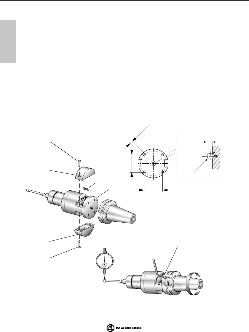
66
FITTING THE TRANSMITTER TO THE TAPER MONTAGGIO DEL TRASMETTITORE SUL CONO
mida
12
12
12.1 FIXING THE TRANSMITTER
Remove the battery compartment covers (C) on the transmitter by removing the screws (D); this
provides access to the four holes (E) on the standard holder.
- Drill four M4 x 8 threaded holes (A) and a central countersink (B) on the taper as shown in
Figure.
- Join the transmitter and the taper inserting the 6 mm diam. ball (G) into the countersink on base
of the taper and into the countersink on the standard holder.
- Lightly tighten the four screws (F).
Aligning the system
- Fit the probe stylus (see “Fitting the probe stylus”).
- Using the four screws (F), align the centre of the stylus sphere with the taper axis.
- When you have completed alignment, tighten the four screws (F) working diagonally.
A = ø M4 x 8
34
(1.34")
34
(1.34")
G = Ø 6
(Ø 0.23")
4,5 ±0,1
(0.17
7±
0
.004
)
F
C
D
C
D
FE
mm

67
BEFESTIGUNG DES SENDERMODULS AM STEILKEGEL MONTAGE DE L’EMETTEUR SUR LE CONE
mida
12
12
12.1 MONTAGGIO DEL TRASMETTITORE
Rimuovere i coperchi batteria (C) del trasmettitore - viti (D) - per accedere ai quattro fori (E) sulla
flangia. Il fissaggio con flangia standard può essere eseguito in due diversi modi:
- Praticare sul cono quattro fori filettati M4x8 (A) e una svasatura centrale (B) come indicato in
figura.
- inserire fra trasmettitore e cono la sfera (G) ø6 mm in dotazione .
- Fissare il trasmettitore al cono mediante le quattro viti (F).
Allineamento del sistema
- Montare il braccetto sonda (vedere "Montaggio del braccetto sonda") .
- Allineare il centro della sfera del braccetto all'asse del cono agendo sulle quattro viti (F).
- Allineato il sistema, serrare le quattro viti (F) con sequenza a croce.
12.1 MONTAGE DES SENDERMODULS MIT STANDARDFLANSCH
Die Batteriefachabdeckungen (C) des Senders - Schrauben (D) - entfernen, um Zugang zu den
vier Flanschbohrungen (E) zu erhalten.
- Am Steikegel Gewindebohrungen M4x8 (A) und eine zentrale Ansenkung (B) realisieren (siehe
Abbildung).
- Zwischen Sender und Steikegel die Kugel (G) ø6 mm (im Lieferumfang) einsetzen .
- Den Sender über die vier Schrauben (F) am Steikegel befestigen.
Systemausrichtung
- Den Tasterarm montieren (siehe "Montage des Tasterarms") .
- Das Zentrum der Tasterarmkugel mit der Steilkegelachse über die vier Schrauben (F) ausrichten.
- Nach der Ausrichtung des Sytems die vier Schrauben (F) kreuzweise anziehen.
12.1 FIXATION EMETTEUR/CONE AVEC BRIDE STANDARD
Retirer les coques porte-batterie (C) de l’émetteur - vis (D) pour accéder aux quatre trous (E) sur
la bride standard.
- Aménager sur le cône 4 trous filetés M4x8 (A) et un évasement central (B) comme le montre
la Figure.
- Assembler l’émetteur et le cône en introduisant la bille (G) de ø6 mm dans l’évasement
aménagé sur la base du cône et dans l’évasement existant sur la bride standard. La bille est
fournie avec l’appareil.
- Visser légèrement les quatre vis (F).
Alignement du système
- Monter le stylet du palpeur (voir “Montage du stylet du palpeur”).
- Aligner le centre de la bille du stylet sur l’axe du cône à l’aide des quatre vis (F).
- Le système étant aligné, serrer les quatre vis (F) suivant un ordre cruciforme.
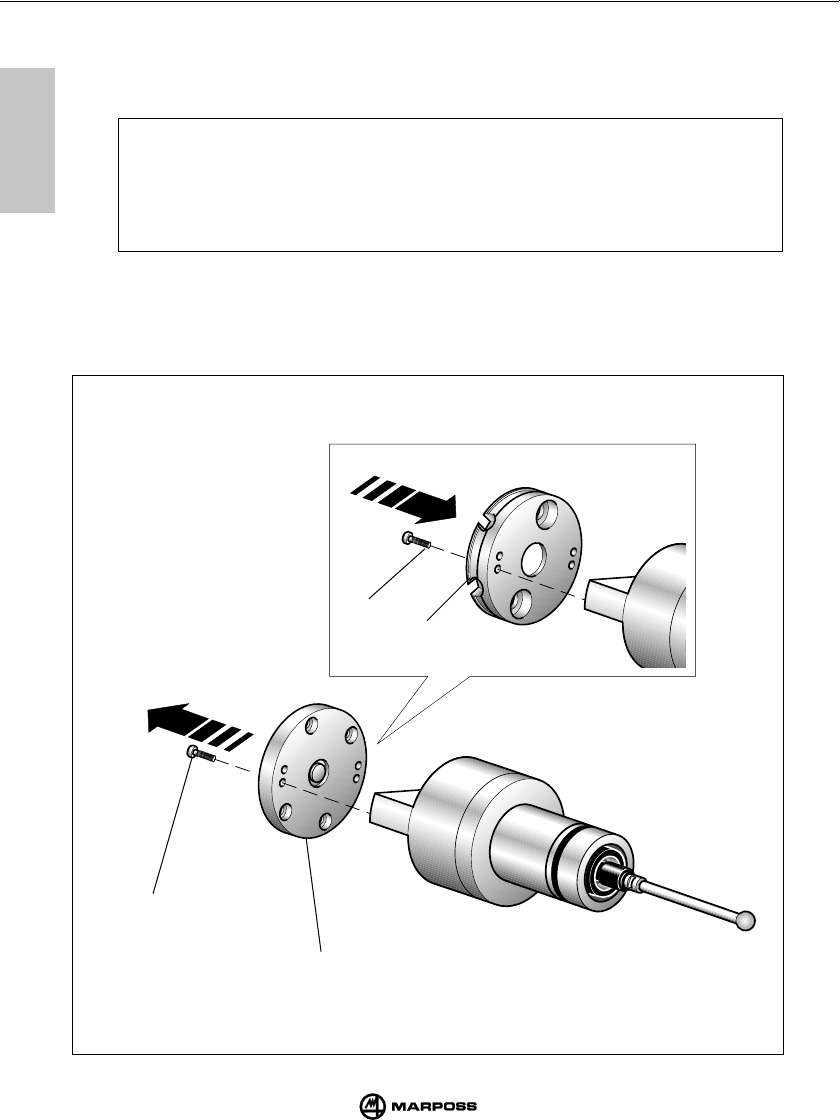
68
FITTING THE TRANSMITTER TO THE TAPER MONTAGGIO DEL TRASMETTITORE SUL CONO
mida
12
12
12.2 FIXING THE TRANSMITTER WITH THE ADJUSTING PLATE
1- Remove the battery compartment covers on the transmitter by removing the screws
(see Chapt. 12.1).
Note: The operations in points 2, 3, 4 and 5 below refer to the transmitter with
radio starting only. Transmitters with mechanical starting (i.e. with a
microswitch on the taper) are supplied complete with a taper and with
the holders already fitted.
For mechanical transmitters continue this fitting procedure from point
6 onwards.
2- Unscrew the four screws (D) and remove the standard holder (C).
3- Fit the adjustable holder (E) to the transmitter using the four screws (D).
(continued ...)
C
D
DE

69
BEFESTIGUNG DES SENDERMODULS AM STEILKEGEL MONTAGE DE L’EMETTEUR SUR LE CONE
mida
12
12
12.2 MONTAGGIO TRASMETTITORE CON FLANGIA DI REGOLAZIONE
1- Rimuovere i coperchi batteria del trasmettitore togliendo le viti (vedere cap.12.1).
Nota: Le operazioni descritte ai punti 2 - 3 - 4 e 5 sono valide solo con trasmettitore con
attivazione radio. Il trasmettitore con attivazione meccanica (microinterruttore
sul cono) viene fornito, comprensivo di cono portatensili, con flangie di regolazione
già montate. In questo caso proseguire dal punto 6.
2- Rimuovere la flangia standard (C) del trasmettitore togliendo le quattro viti (D).
3- Fissare al trasmettitore la flangia di regolazione (E) mediante le quattro viti (D).
12.2 BEFESTIGUNG MIT REGULIERFLANSCH
1- Die Deckel des Batteriefachs des Sendermoduls über die Schrauben abnehmen (seihe Kap.
12.1).
Hinweis: Die unter den Punkten 2 - 3 - 4 und 5 beschriebenen Vorgänge gelten nur für
Sender mit Funkaktivierung.
Der Sender mit mechanischer Aktivierung (Mikroschalter auf Steilkegel) wird
komplett mit Steilkegel und bereits montiertem Regulierflansch geliefert. In
diesem Fall die Vorgänge ab Punkt 6 ausführen.
2- Den Standardflansch (C) des Sendermoduls abnehmen; dazu die vier Schrauben (D) lösen.
3- Das teil (E) des regulierflansches mit den vier Schrauben (D) am Sendermodul befestigen.
12.2 FIXATION EMETTEUR/CONE AVEC BRIDE DE REGLAGE
1- Retirer les coques porte-batterie de l’émetteur en dévissant les quatre vis (voir chap.
12.1).
Note: Les opérations décrites aux points 2 - 3 - 4 et 5 ne sont valables que pour
l’émetteur avec activation radio.
L’émetteur avec activation mécanique (micro-interrupteur sur le cône)
est fourni avec le cône porte-outils et les brides de réglage montées. Dans ce
cas, passer au point 6.
2- Retirer la bride standard (C) de l’émetteur en dévissant les quatre vis (D).
3- Fixer la bride de réglage (E) à l’émetteur au moyen des quatre vis (D).
(segue ...)
(weiter ...)
(suite ...)
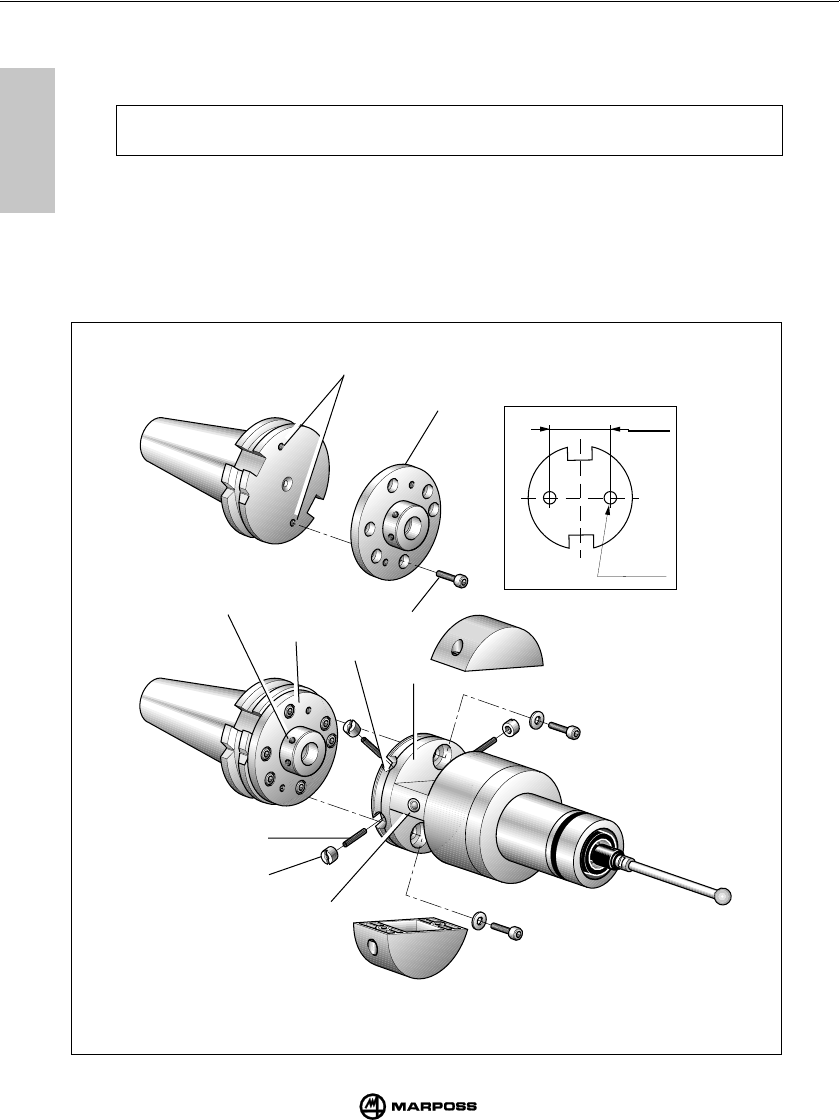
70
FITTING THE TRANSMITTER TO THE TAPER MONTAGGIO DEL TRASMETTITORE SUL CONO
mida
12
12
==
F
G
H
M
E
N
G
Q
P
L
12.2 FIXING THE TRANSMITTER WITH THE ADJUSTING PLATE
4- Drill two M4 x 8 threaded holes (F) on the tool taper as shown in Figure.
5- Fix the adjustable holder (G) to the tool taper using the two screws (H).
Note: The holder (G) has three pairs of fixing holes to enable correct angular orientation
of the transmitter LED (L) toward the operator.
6- Join the transmitter to the taper. Match up the four threaded holes (M) on the taper holder (G)
with the four slots (N) on the transmitter holder (E).
7- Insert the four threaded stud screws (P) through the slots (N) and into the threaded holes (M)
and tighten using the spanner provided.
8- Fit and tighten the four special nuts (Q) on the stud screws.
F = M4X8
(continued ...)
36
(1.42")

71
BEFESTIGUNG DES SENDERMODULS AM STEILKEGEL MONTAGE DE L’EMETTEUR SUR LE CONE
mida
12
12
12.2 MONTAGGIO TRASMETTITORE CON FLANGIA DI REGOLAZIONE
4- Praticare sul cono portautensili due fori filettati M4x8 (F).
5- Fissare al cono portautensili la flangia di regolazione (G) mediante le due viti (H).
Nota: Per facilitare l'orientamento del LED (L) del trasmettitore verso l' operatore, sono
disponibili tre coppie di fori di fissaggio che permettono di scegliere la posizione
angolare più idonea.
6- Unire i due gruppi (trasmettitore-cono) facendo combaciare i quattro fori filettati (M) della
flangia cono (G) con le quattro asole (N) della flangia trasmettitore (E).
7- Inserire i quattro prigionieri filettati (P) nelle asole (N) e avvitarli nei fori filettati (M) della
flangia cono mediante la chiave esagonale in dotazione.
8- Avvitare i quattro dadi speciali (Q) sui prigionieri.
12.2 BEFESTIGUNG MIT REGULIERFLANSCH
4- Am Steilkegel 2 Gewindebohrungen M4x8 (F) gemäß Abbildung herstellen.
5- Den Regulierflansch (G) mit zwei Schrauben (H) am Steilkegel befestigen.
Hinweis:
Um die Orientierung der LED (L) am Sender zur Bedienseite zu erleichtern,
stehen drei Bohrungspaare für eine optimale Orienterung zur Verfügung.
6- Das Sendermodul anbauen, wobei darauf zu achten ist, daß die 4 Gewinde (M) des Teils (G)
des Regulierflansches den 4 Langlöchern (N) des Senderflansches (E) gegenüberstehen.
7- Die 4 Gewindebolzen (P) in die Langlöcher (N) einführen und in die Gewinde (M) des
Kegelflansches mit Innensechskantschlüssel einschrauben.
8- Die vier Spezialmuttern (Q) auf die Gewindebolzen anschrauben.
12.2 FIXATION EMETTEUR/CONE AVEC BRIDE DE REGLAGE
4- Aménager sur le cône porte-outils 2 trous filetés M4x8 (F) comme le montre la Figure.
5- Fixer la bride de réglage (G) au cône porte-outils au moyen des deux vis (H).
Nota: Pour mieux diriger la diode (L) de l’émetteur vers le operateur, la bride (G)
comprend trois paires de trous pour la fixation qui servent à déterminer la position
angulaire la plus appropriée.
6- Assembler les deux groupes (émetteur - cône) en faisant correspondre les quatre trous
filetés (M) de la bride cône (G) avec les quatre boutonnières (N) de la bride émetteur (E).
7- Introduire les quatre goujons filetés (P) dans les boutonnières (N), puis les visser dans les
trous filetés (M) de la bride cône en utilisant la clé à six pans fournie avec l’appareil.
8- Visser les quatre écrous spéciaux (Q) sur les goujons.
(segue ...)
(weiter ...)
(suite ...)
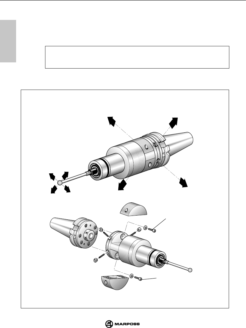
72
FITTING THE TRANSMITTER TO THE TAPER MONTAGGIO DEL TRASMETTITORE SUL CONO
mida
12
12
12.2 FIXING THE TRANSMITTER WITH THE ADJUSTING PLATE
Aligning the system
9- Fit the probe stylus (see “Fitting the probe stylus”).
10 - Using the four special nuts (Q), align the centre of the stylus sphere with the taper axis.
Maximum permitted travel: 1.7 mm in the four directions.
Example:
To move the stylus sphere towards "- X", —> tighten (Q1) or loosen (Q2) as required.
Use this method for the other directions.
11 - When you have completed alignment, fit and tighten the two clamping screws (R).
Y
X
-X
Q1
Q2
+X
R
R

73
BEFESTIGUNG DES SENDERMODULS AM STEILKEGEL MONTAGE DE L’EMETTEUR SUR LE CONE
mida
12
12
12.2 MONTAGGIO TRASMETTITORE CON FLANGIA DI REGOLAZIONE
Allineamento del sistema
9- Montare il braccetto sonda (vedi "Montaggio del braccetto sonda").
10 - Allineare il centro della sfera del braccetto all'asse del cono agendo sui quattro dadi speciali (Q).
Massima traslazione ammessa: 1,7 mm nelle quattro direzioni.
Esempio:
Traslazione della sfera braccetto verso "-X" —> allentare (Q1) e avvitare (Q2).
Procedere in modo analogo per le altre direzioni.
11 - Allineato il sistema procedere al bloccaggio del gruppo di regolazione; inserire e serrare le
due viti (R) di bloccaggio.
12.2 BEFESTIGUNG MIT REGULIERFLANSCH
Systemausrichtung
9- Den Tasterarm des Schaltmeßkopfes montieren (siehe “Montage des Tasterarms”)
10 - Das Zentrum der Meßtasterkugel mit Hilfe der vier Spezialmuttern (Q) auf die Steilkegelachse
ausrichten. Max. zulässige Verstellung: 1,7 mm in die vier Richtungen.
Beispiel:
Verstellung der Meßtasterkugel in ‘-X’ Richtung —> (Q1) lockern und (Q2) nachstellen.
Für die anderen Richtungen analog vorgehen.
11 - Ist das System ausgerichtet, muß die Reguliereinheit gesichert werden: die beiden
Blockierschrauben (R) einsetzen und anziehen.
12.2 FIXATION EMETTEUR/CONE AVEC BRIDE DE REGLAGE
Alignement du système
9- Monter le stylet du palpeur (voir “Montage du stylet du palpeur”).
10 - Aligner le centre de la bille du stylet sur l’axe du cône en agissant sur les quatre écrous
spéciaux (Q). Translation maximale admise: 1,7 mm dans les quatre directions.
Exemple:
Translation de la bille du stylet vers ‘-X’ —> desserrer (Q1) et serrer (Q2).
Procéder de la même manière pour les autres directions.
11 - Le système aligné, procéder au blocage du groupe de réglage: introduire et serrer les deux
vis (R) de blocage.
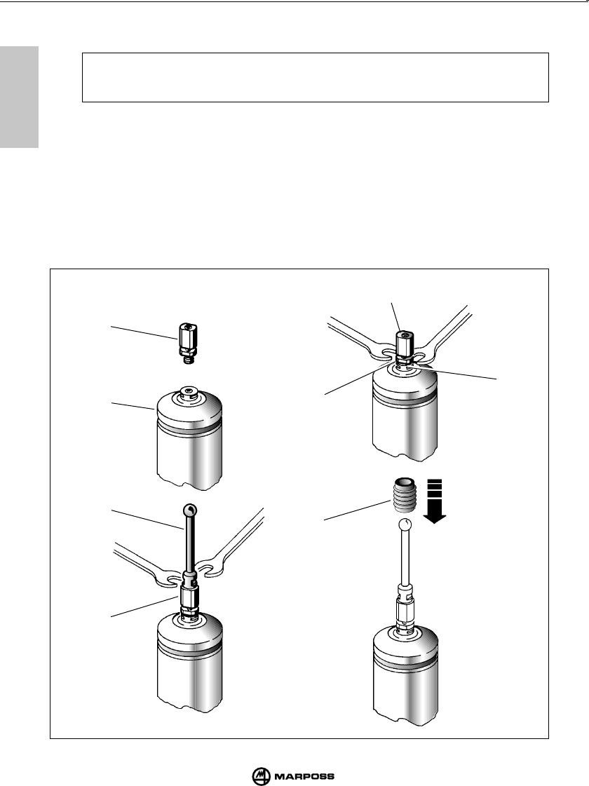
74
FITTING THE PROBE STYLUS MONTAGGIO DEL BRACCETTO SONDA
mida
13
13
13.1 FITTING THE PROBE STYLUS
To fit the stylus to the probe, proceed as follows:
Note: The procedure described below involves the fitting of a break pin between the probe and
the stylus. The purpose of the break pin is to protect the stylus from damage in the event
of accidental knocks or blows to the probe by disconnecting the stylus from the probe.
- Fit the break pin (A) to the probe (B).
- Using the spanner provided, hold the stylus holder (C) in position and then, using the other
spanner, tighten the break pin (A).
To tighten the break pin (A), insert the spanner in position (D) on the lower part of the pin.
- Screw the stylus (F) onto the break pin (A). Using one spanner, hold the break pin in position
and, using the other spanner provided, tighten the stylus.
- Fit the holder (E) over the stylus and slide it down to cover the break pin (A).
The purpose of this holder is to hold the stylus in place when the break pin breaks.
- If the break pin is not to be used, screw the stylus directly onto the probe. Hold the stylus holder (C)
in position with the spanner provided and then tighten the stylus with the other spanner.
A
B
F
A
D
E
C
A

75
MONTAGE DES TASTERARMS MONTAGE DU STYLET DU PALPEUR
mida
13
13
13.1 MONTAGGIO DEL BRACCETTO SONDA
Per il montaggio del braccetto sulla sonda procedere nel seguente modo:
Nota: La procedura descritta di seguito prevede l'impiego della spina di rottura. Tale
spina, interposta tra braccetto e sonda, ha il compito di salvaguardare la sonda in
caso di urti accidentali sul braccetto (avviene il distacco del braccetto della sonda).
- Inserire la spina di rottura (A) sulla sonda (B).
- Con la chiave (in dotazione) tenere fermo il portabraccetto (C) della sonda e con l'altra chiave,
serrare la spina di rottura (A). La chiave per serrare la spina (A), va inserita nella parte inferiore
della spina stessa - posizione (D).
- Avvitare il braccetto (F) sulla spina di rottura (A).
Con una chiave tenere ferma la spina e con l'altra, serrare il braccetto.
- Inserire il ritegno (E), facendolo scorrere lungo il braccetto stesso fino ad avvolgere la spina di
rottura (A). Questo ritegno ha lo scopo di trattenere il braccetto, in caso di rottura della spina.
Nel caso non venga utilizzata la spina di rottura avvitare il braccetto direttamente sulla sonda;
con una chiave tenere fermo il portabraccetto (C) e con l'altra serrare il braccetto.
13.1 MONTAGE DES TASTERARMS
Zur Montage des Tasterarms am Schaltmeßkopf ist wie folgt vorzugehen:
Hinweis: Der unten beschrieben Ablauf sieht den Einsatz des Sollbruchstückes vor. Dieser
Stift, der zwischen Tasterarm und Schaltmeßkopf eingesetzt wird, schützt diesen
bei versehentlichen extremen Tasterarmauslenkungen vor Zerstörung, indem
zuerst das Sollbruchstück bricht.
- Das Sollbruchstück (A) in den Schaltmeßkopf (B) schrauben.
- Mit dem (mitgelieferten) Gabelschlüssel die Tasterarmaufnahme (C) des Meßkopfs festhalten
und mit dem anderen Gabelschlüssel in Position (D) das Sollbruchstück (A) anschrauben.
- Den Tasterarm (F) am Sollbruchstück (A) anschrauben. Mit einem Gabelschlüssel das
Sollbruchstück festhalten und mit dem anderen Gabelschlüssel den Tasterarm anschrauben.
- Die Sicherungshülse (E) vollständig über das Sollbruchstück schieben. Die Hülse hält den
Tasterarm beim eventuellen Bruch des Sollbruchstückes.
Wird kein Sollbruchstück verwendet, den Tasterarm direkt am Meßkopf anschrauben; dazu
mit einem Gabelschlüssel die Tasterarmaufnahme (C) festhalten und mit dem anderen
Gabelschlüssel den Tasterarm anschrauben.
13.1 MONTAGE DU STYLET DU PALPEUR
Pour monter le stylet sur le palpeur, procéder comme suit:
Note: Le procédé décrit ci-après prévoit l’utilisation de la goupille de rupture. Cette
goupille, interposée entre le stylet et le palpeur, a pour objet de protéger le palpeur
en cas de chocs accidentels au niveau du stylet (le stylet se détache du palpeur).
- Placer la goupille de rupture (A) sur le palpeur (B).
- A l’aide de la clé (fournie avec l’appareil) maintenir bloqué le support du stylet (C) du palpeur,
et à l’aide de l’autre clé, serrer la goupille de rupture (A). La clé pour serrer la goupille (A) doit
être placée sur la partie inférieure de la goupille elle-même - position (D).
- Visser le stylet (F) sur la goupille de rupture (A).
Maintenir bloquée la goupille à l’aide d’une des clés et, avec l’autre, serrer le stylet.
- Mettre en place la fixation de sécurité (E) et la faire glisser sur toute la longueur du stylet jusqu’à
la positionner sur la goupille de rupture (A).
Cette fixation a pour but de maintenir en place le stylet en cas de rupture de la goupille.
Au cas où la goupille de rupture ne serait pas utilisée, visser le stylet directement sur le palpeur.
Maintenir bloqué le support du stylet (C) à l’aide de l’une des clés et, avec l’autre, serrer le stylet.
76
DIAGNOSTICS DIAGNOSTICA
mida
14
14
No power supply Check that power is arriving at terminals 13 and 14 on the
terminal board of the interface unit.
Fuse open Wait some minutes with interface unit not powered
Transmitter-Antenna out of
transmission range
Transmitter battery low or completely
discharged
Transmission time has elapsed
No electrical connection between the
antenna and the interface unit
Electrical or electromagnetic
interference
Check that the green “tuning” LED on the antenna
remains lit during probe movement.
Change the battery.
Give the start signal to restart the system.
Check the connecting cable and connections between
the antenna and the interface unit.
Move the antenna cable away from other power cables
Change working channel
REMEDY REMEDY
Probe LED does not change status when the probe is touched
No electrical connection between the
probe and the transmitter
Probe is damaged
Transmitter damaged
Check the electrical connection between the probe and
the transmitter.
Remove the probe from the transmitter. Connect the
spring contacts and then break the connection.
If the LED continues not to change status, this indicates
that the transmitter if faulty. If the LED changes status,
this indicates that the probe is faulty.
REMEDY
14.1 FAULT FINDING GUIDE
Faults are indicated by the LED on the interface unit panel.
Error LED is lit
Power LED off
REMEDY
Stylus is loose
Holder is loose
Seal is pierced or damaged
Check that the stylus and the break pin (where fitted)
are fully tightened on the probe.
Tighten all screws.
Change the probe.
Poor repeatability
CAUSE CAUSE
CAUSE
CAUSE

77
DIAGNOSE DIAGNOSTIC
mida
14
14
Assenza di alimentazione Verificare che ai capi dei morsetti 13 e 14 della morsettiera
dell'unità di interfaccia vi sia tensione.
Fusibile ripristinabile aperto Attendere alcuni minuti con interfaccia non alimentata.
Led "error" acceso
Trasmettitore-Antenna fuori campo
di trasmissione
Batteria trasmettitore totalmente
scarica o assente
Scaduto tempo di trasmissione
Mancanza di collegamento elettrico
tra antenna ed interfaccia
Vi è interferenza elettrica o elettroma-
gnetica
Accertarsi che durante i movimenti della sonda il led verde
"tuning" presente sul ricevitore rimanga acceso.
Sostituirla.
Dare un segnale di start per riattivare il sistema.
Verificare il cavo del ricevitore e le relative connessioni
all'interfaccia.
Allontanare il cavo proveniente dall' antenna da eventuali
cavi di potenza.
Cambiare canale di lavoro.
RIMEDI
Led "probe": non cambia stato al tocco della sonda
Non c'è collegamento elettrico tra
sonda e trasmettitore
Sonda danneggiata
Trasmettitore danneggiato
Verificare il collegamento elettrico tra sonda e trasmet-
titore.
Smontare la sonda dal trasmettitore, collegare tra loro i
contatti a molla ed interrompere il contatto. Se nonostan-
te ciò il led non cambia stato, il trasmettitore è guasto. Se
cambia stato significa che la sonda è guasta.
RIMEDI
Led "power" spento
RIMEDI
14.1 RICERCA GUASTI E ANOMALIE
Indicazione dei led presenti sul pannello dell’unità di interfaccia.
Scarsa ripetibilità
RIMEDI
Braccetto allentato
Flangia allentata
Guarnizione interna forata o
danneggiata
Controllare che il braccetto e la spina di rottura (se
utilizzata) siano bene avvitati alla sonda.
Avvitare tutte la viti.
Sostituire la sonda.
CAUSE
CAUSE CAUSE
CAUSE

78
DIAGNOSTICS DIAGNOSTICA
mida
14
14
Keine Stromversorgung Überprüfen, ob an den Klemmen 13 und 14 der Klemmleiste
der Schnittstelleneinheit 24 V DC anliegen.
Elektronische offen Einige Minuten bei abgeschalteter Stromversorgung
warten.
14.1 FEHLERSUCHE
LED-Anzeigen auf der Frontseite der Schnittstelleneinheit
“power” - LED aus
URSACHE
MASSNAHME
Mangelnde Wiederholbarkeit
MASSNAHME
URSACHE
Tasterarm locker
Flansch locker
Innere Dichtung beschädigt
Prüfen, ob Tasterarm und Sollbruchstück (falls
verwendet) fest am Schaltmeßkopf angeschraubt sind.
Alle Schrauben anziehen.
Schaltmeßkopf ersetzen.
“error” - LED ein
Sender - Empfänger außerhalb des
Übertragungsbereichs
Batterie des Senders leer oder fehlt
Übertragungszeit abgelaufen
Keine elektrische Verbindung
zwischen Empfänger und Schnitt-
stelleneinheit
Elektrische oder elektromagnetische
Interferenz
Prüfen, ob während der Verfahrbewegungen des
Schaltmeßkopfes die grüne “tuning”-LED auf dem
Empfänger an bleibt.
Ersetzen
Ein Start/Reset-Signal geben, um das System erneut
zu aktivieren.
Das Kabel des Empfängers und die entsprechenden
Anschlüsse an der Schnittstelleneinheit prüfen.
Das Kabel vom Empfänger aus der Umgebung
eventueller Leistungskabel entfernen.
Empfangskanal ändern.
MASSNAHME
URSACHE
Keine elektrische Verbindung
zwischen Schaltmeßkopf und
Sender
Schaltmeßkopf defekt
Sender defekt
“probe”-LED schaltet beim Antasten des Schaltmeßkopfes nicht um
Die elektrische Verbindung zwischen Schaltmeßkopf
und Sender prüfen. Dazu den Schaltmeßkopf vom
Sender abnehmen.
Die gefederten Kontakte untereinander verbinden und
dann den Kontakt unterbrechen.
Schaltet die LED immer noch nicht um, ist der Sender
defekt. Schaltet sie um, ist der Schaltmeßkopf defekt.
URSACHE
MASSNAHME
79
DIAGNOSE DIAGNOSTIC
mida
14
14
Vérifier si pendant les mouvements du palpeur, la LED
verte “tuning” sur le récepteur reste allumée.
La remplacer.
Donner un signal de start/reset (marche/RAZ) pour
réactiver le système.
Vérifier le câble du récepteur et ses connexions avec
l’unité d’interface.
Eloigner le câble provenant du récepteur et les câbles
de puissance éventuels.
Changer le chanel.
Manque d’alimentation Vérifier la présence de tension aux bouts des bornes 13
et 14 du bornier de l’unité d’interface.
Fusible de la carte d’alimentation Vérifier l’état du fusible et le remplacer si nécessaire.
cassé
14.1 RECHERCHE DE PANNES ET DÉFAILLANCES
Indication des LEDS sur le panneau de l’unité d’interface
LED “error” allumée
Emetteur/Récepteur en dehors de
la zone d’émission
Batterie de l’émetteur épuisée ou
absente
Fin du temps d’émission
Manque de liaison électrique entre
le récepteur et l’unité d’interface
Présence d’interférences électriques
REMEDE
CAUSE
LED “power” éteinte
CAUSE
REMEDE
LED “probe”: son état ne change pas au touché du palpeur
Manque de liaison électrique entre
le palpeur et l’émetteur
Palpeur endommagé
Emetteur endommagé
Vérifier la liaison électrique entre le palpeur et l’émetteur.
Désassembler le palpeur de l’émetteur, relier entre eux
les contacts à ressort existants et couper le contact. Si
l’état de la LED ne change toujours pas, l’émetteur est en
panne. Si la LED change d’état, le palpeur est en panne.
REMEDE
CAUSE
Répétabilité insuffisante
REMEDE
CAUSE
Stylet desserré
Bride desserrée
Joint percé ou endommagé
Vérifier si le stylet et la goupille de rupture (si montée)
sont bien vissés au palpeur.
Serrer toutes les vis.
Remplacer le joint.

80
MAINTENANCE MANUTENZIONE
mida
15
15
15.1 ORDINARY MAINTENANCE
15.1.1 CLEANING AND INSPECTION
To ensure top, trouble-free performance, clean and inspect the measuring system at regular
intervals. Cleaning and inspection intervals must be defined in accordance with operation
conditions.
- Checking cable condition
Check the cable condition and the tightness of the cable clamps at regular intervals.
- Checking seal condition
The front of the probe is fitted with two seals which provide optimum protection under normal
operating conditions. At regular intervals, check the outer seal for signs of wear. Change worn
seals. If the inner seal is damaged, return the probe to the manufacturer for repair.
15.1 MANUTENZIONE ORDINARIA
15.1.1 PULIZIA E CONTROLLI
Per ottenere sempre le migliori prestazioni dal sistema di misura, è buona norma sottoporlo a
regolari operazioni di pulizia e controllo.
Si tratta di operazioni semplici da eseguire periodicamente in funzione delle condizioni di
impiego.
- Verifica integrità cablaggio
Verificare periodicamente l'integrità dei cavi ed il serraggio dei morsetti elettrici.
- Controllo tenuta guarnizioni
Anteriormente la sonda è protetta da due guarnizioni sufficienti per un'ottima protezione in
normali condizioni di impiego. Controllare periodicamente che la guarnizione esterna non
presenti segni di usura. In tal caso, provvedere alla sostituzione della guarnizione stessa.
In caso di danneggiamento della guarnizione interna, la sonda dovrà essere inviata al fornitore
per la riparazione.

81
WARTUNG ENTRETIEN
mida
15
15
15.1 REGELMÄSSIGE WARTUNG
15.1.1 REINIGUNG UND KONTROLLEN
Um stets die optimale Leistung sicherzustellen, sollte das Meßsystem regelmäßig gereinigt und
kontrolliert werden.
Es handelt sich um einfache Arbeiten, die je nach Einsatzbedingungen regelmäßig auszuführen
sind.
-Kontrolle der Verkabelung
Die Kabel und die Klemmverbindungen regelmäßig auf einwandfreien Zustand prüfen.
-Kontrolle der Dichtungen
Der Schaltmeßkopf ist vorne mit zwei Dichtungen versehen, die unter normalen
Einsatzbedingungen einen ausgezeichneten Schutz bieten. Die äußere Dichtung regelmäßig
auf Abnutzung prüfen. Falls erforderlich, die Dichtung auswechseln.
Ist die innere Dichtung beschädigt, muß der Schaltmeßkopf zur Reparatur an den Lieferanten
geschickt werden.
15.1 ENTRETIEN ORDINAIRE
15.1.1 NETTOYAGE ET CONTROLES
Pour obtenir toujours les meilleures performances du système de mesure, il est recommandé de
le nettoyer et le contrôler régulièrement.
Il s’agit d’opération très simples, à effectuer périodiquement suivant les conditions d’utilisation.
-Vérification du câblage
Vérifier régulièrement l’état des câbles et le serrage des bornes électriques.
-Contrôle de l’étanchéité des joints
Le palpeur est protégé sur sa face avant par deux joints qui assurent une protection optimale
dans des conditions d’utilisation ordinaires. Vérifier périodiquement l’état du joint extérieur qui
ne doit présenter aucun signe d’usure. Si c’est le cas, remplacer le joint.
Si le joint intérieur est endommagé, il est nécessaire de retourner le palpeur au fournisseur
pour son dépannage.
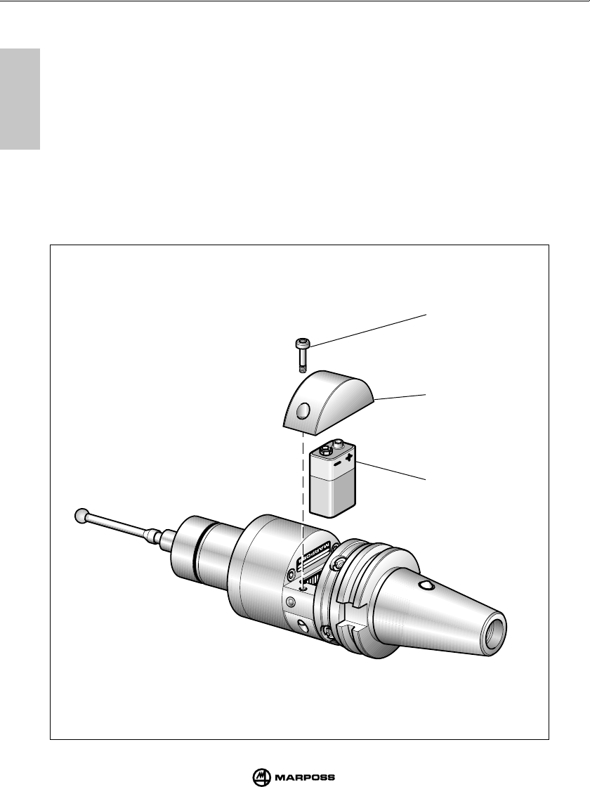
82
MAINTENANCE MANUTENZIONE
mida
15
15
15.1.2 FITTING/CHANGING THE BATTERY
The transmitter battery must be changed when the “low battery” LED on the interface unit lights
up and when the LOW BAT output signal is transmitted.
To change the battery, proceed as follows:
- Unscrew the two screws (A) of the battery compartment cover (C) (marked with the battery
symbol).
- Remove the old battery and insert the new battery (B) into the battery compartment cover (C)
ensuring that the poles match.
- Refit the cover (C) noting the electrical contacts.
- Refit and tighten the cover retaining screws (A).
In to chapt. 7.2 “Battery Life” shows the duration of different battery types under various
operating conditions.
B
C
A

83
WARTUNG ENTRETIEN
mida
15
15
15.1.2 INSERIMENTO / SOSTITUZIONE BATTERIA TRASMETTITORE
Per l'inserimento della batteria nel trasmettitore o per la sua sostituzione in seguito all'accensio-
ne del led "low battery" sul pannello unità interfaccia e attivazione del segnale di uscita
LOW BATTERY, procedere nel seguente modo:
- Svitare le due viti (A) del coperchio (C) contrassegnato dal simbolo grafico della batteria.
- Togliere la batteria scarica, se presente, e innestare la nuova batteria (B) negli appositi contatti
del coperchio (C) rispettando la polarità.
- Riposizionare il coperchio (C) prestando attenzione alla posizione dei contatti elettrici.
- Riavvitare le viti (A).
Nel cap. 7.2 “Durata batteria trasmettitore” è indicata la durata della batteria in rapporto
all'impiego e al tipo.
15.1.2 EINSETZEN/WECHSEL DER SENDERBATTERIE
Zum Einsetzen der Batterie in den Sender oder zum Batteriewechsel nach dem Aufleuchten der
“low battery”-LED auf der Fronttafel der Schnittstelleneinheit bzw. der Ausgabe des Signals
LOW BAT, ist wie folgt vorzugehen:
- Die beiden Schrauben (A) des Deckels (C) mit dem Batteriesymbol lösen.
- Die leere Batterie entnehmen (falls vorhanden) und die neue Batterie (B) in das Batteriefach
des Deckels (C) einsetzen; Pole beachten.
- Den Deckel (C) wieder anbringen; auf die Kontakte achten.
- Die Schrauben (A) wieder einschrauben.
In Kap. 7.2 “Lebensdauer der Senderbatterie” ist die Lebensdauer der Batterie bezogen auf
Einsatz und Batterietyp angegeben.
15.1.2 MISE EN PLACE/REMPLACEMENT DE LA BATTERIE DE L’EMETTEUR
Pour mettre en place la batterie dans l’émetteur, ou pour la remplacer quand la LED “LOW
BATTERY” sur le panneau de l’unité d’interface s’allume et que le signal de sortie LOW BAT
s’active, procéder comme suit:
- Dévisser les deux vis (A) de la demi-coque (C) repérée par le symbole graphique de la batterie.
- Retirer la batterie épuisée, si montée, puis brancher la nouvelle batterie (B) sur les contacts de
la demi-coque (C) correspondants en respectant la polarité.
- Remettre en place la demi-coque (C) en veillant à respecter la bonne position des contacts
électriques.
- Revisser les vis (A).
Le chapt. 7.2 “Durée de la batterie de l’émetteur” montre la durée de la batterie suivant
l’utilisation et le type.
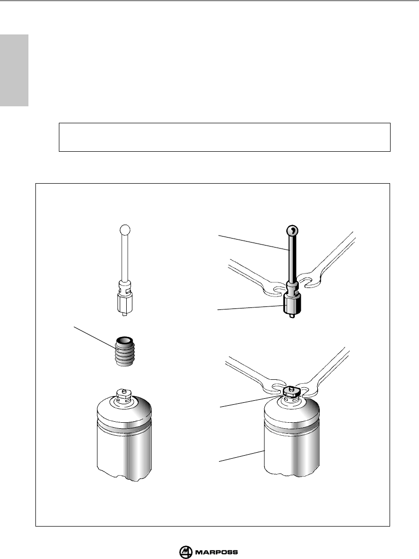
84
MAINTENANCE MANUTENZIONE
mida
15
15
B
D
D
C
A
15.2 EXTRAORDINARY MAINTENANCE
15.2.1 CHANGING THE BREAK PIN AND THE STYLUS
Should the stylus or break pin become damaged due to an accidental knock to the probe they
must be replaced.
Proceed as follows:
1- Slide the holder (A) off the broken or bent break pin.
2- Unscrew stylus (B) and the probe (C) from the broken break pin (D).
Remove the damaged stylus from the probe (C).
Note: During the above operation hold the stylus holder clamped in position using the
spanner provided.
3- Fit the new break pin and stylus (see “Fitting the probe stylus”).

85
WARTUNG ENTRETIEN
mida
15
15
15.2 MANUTENZIONE STRAORDINARIA
15.2.1 SOSTITUZIONE SPINA DI ROTTURA/BRACCETTO
In caso di urti accidentali sul braccetto provvedere come segue alla sostituzione della spina rotta
e/o del braccetto.
1- Liberare il ritegno (A) sfilandolo dalla spina rotta o piegata.
2- Liberare il braccetto (B) e la sonda (C) dalla spina rotta (D).
Rimuovere il braccetto danneggiato dalla sonda (C).
Nota: Eseguire queste operazioni tenendo fermo il portabraccetto della sonda con la
chiave in dotazione.
3- Procedere quindi al montaggio della nuova spina e del braccetto (vedere "Montaggio del
braccetto sonda").
15.2 AUSSERORDENTLICHE WARTUNG
15.2.1 AUSTAUSCH DES SOLLBRUCHSTÜCKS/TASTERARMS
Im Falle einer Kollision des Tasterarms ist das gebrochene Sollbruchstück und/oder der verbogene
Tasterarm wie folgt auszutauschen:
1- Die Sicherungshülse (A) vom gebrochenen Sollbruchstück abziehen.
2- Den Tasterarm (B) und den Schaltmeßkopf (C) von den gebrochenen Teilen (D) befreien.
Hinweis: Bei diesen Vorgängen die Tasterarmaufnahme des Schaltmeßkopfs mit einem
Schlüssel festhalten.
3- Nun den neuen Stift und Tasterarm montieren (siehe “Montage des Tasterarms”).
15.2 ENTRETIEN EXTRAORDINAIRE
15.2.1 REMPLACEMENT DE LA GOUPILLE DE RUPTURE ET/OU DU STYLET
Dans le cas de chocs accidentels sur le stylet, remplacer la goupille rompue ou pliée et/ou le
stylet, en procédant comme suit:
1- Dégager la fixation de sécurité (A) en la retirant de la goupille rompue ou pliée.
2- Dégager le stylet (B) et le palpeur (C) de la goupille rompue (D).
Retirer le stylet endommagé du palpeur (C).
Nota: Effectuer ces opérations en maintenant bloqué le support du stylet du palpeur à
l’aide d’une clé appropriée.
3- Monter la nouvelle goupille et le nouveau stylet (voir “Montage du stylet du palpeur”).
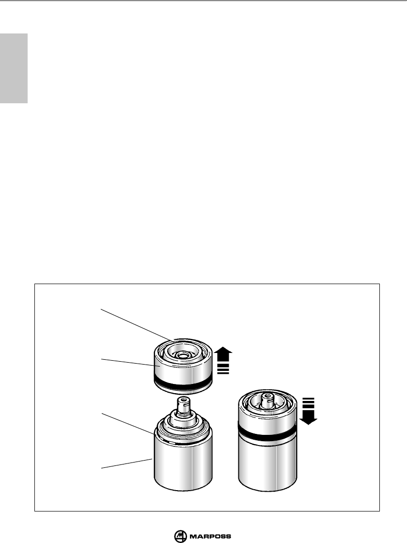
86
MAINTENANCE MANUTENZIONE
mida
15
15
15.2.2 REPLECEMENT OF OUTER SEAL
1- Remove the sensing stylus and protection pin, if any.
2- Remove the front protection cover (B) and seal (C) from the probe body (A).
3- Check for wear of the front seal (D) and, if necessary, replace.
4- Fit the new front protection cover and seal until it snaps into place.
15.2.2 SOSTITUZIONE GUARNIZIONE ESTERNA
1- Togliere il braccetto e l'eventuale spina di rottura.
2- Sfilare dal corpo sonda (A) la protezione anteriore (B) con guarnizione (C).
3- Controllare lo stato dell'anello di tenuta anteriore (D) ed eventualmente sostituirlo.
4- Inserire la nuova protezione anteriore con guarnizione fino a scatto avvenuto.
15.2.2 ERSETZEN DER SCHUTZKAPPE MIT DICHTUNG
1- Tasterarm und Sollbruchstück entfernen.
2- Schutzkappe (B) mit Dichtung (C) vom Meßkopf (A) ziehend abschrauben.
3- Dichtung (D) überprüfen und gegebenenfalls ersetzen.
4- Schutzkappe wieder aufsetzen und andrücken, bis sie einrastet.
15.2.2 REPLACEMENT DU JOINT EXTERIEUR
1- Enlever le bras et la broche de rupture éventuelle.
2- Avec un mouvement de rotation, ex-traire du corps (A) la protection avant (B) avec le joint (C).
3- Contrôler l'état de la bague d'étanchéité avant (D) et la remplacer.
4- Insérer la nouvelle protection avant avec joint jusqu'à l'encliquetage.
C
A
B
D

87
WARTUNG ENTRETIEN
mida
15
15
15.2.3 CHANGING THE PROBE FROM THE TRANSMITTER
1- Remove the stylus and break pin (where fitted). (See “Fitting the probe stylus”)
2- Change the probe as indicated in “Assembling and dismantling the probe to the transmitter”.
15.2.3 SOSTITUZIONE SONDA/TRASMETTITORE
1- Togliere il braccetto e l'eventuale spina di rottura. Vedere "Montaggio del braccetto sonda"
2- Procedere alla sostituzione della sonda come indicato in "Montaggio/smontaggio sonda-
trasmettitore".
15.2.3 AUSTAUSCH DES SCHALTMESSKOPFES
1- Den Tasterarm und eventuell das Sollbruchstück abschrauben.
Siehe “Montage des Tasterarms”.
2- Den Schaltmeßkopf austauschen, wie unter “An- und Abbau der Schaltmeßköpfe am/vom
Sendermodul“ beschrieben.
15.2.3 REMPLACEMENT DU PALPEUR/EMETTEUR
1- Retirer le stylet et la goupille de rupture (si montée). Voir “Montage du stylet du palpeur”.
2- Remplacer le palpeur comme décrit au point “Montage/démontage palpeur/émetteur”.
88
SPARE PART LIST LISTA RICAMBI
mida
16
16
INTERFACE ANTENNA
1019108005 Crash protection pin 15 mm (0.59")
1019108003 Stylus retainer
2915335007 Spare part kit for T25G/TL25G I
NCLUDING
: probe shield with
rubber seal, probe (front-rear)
o-ring and stylus retainer
2915340010 Spare part kit for T36G I
NCLUDING
: probe shield with
rubber seal, probe front o-ring
and stylus retainer
2915345007 Spare part kit for T60G I
NCLUDING
: probe shield with
rubber seal, probe front o-ring
and stylus retainer
2915335011 Front protection for T25G/TL25G
2915340006 Front protection for T36G
2915345012 Front protection for T60G
3415335031 Touch probe T25G
3424306010 Touch probe TL25G
3415340050 Touch probe T36G
3415345030 Touch probe T60G
2019923021 Transmitter fixing flange for T25G/TL25G Complete with o-ring seals
2019923022 Transmitter fixing flange for T36G Complete with o-ring seals
2019923023 Transmitter fixing flange for T60G Complete with o-ring seals
2915335100 Extension for probe T25G/TL25G L=50 mm (1.97")
2915335110 Extension for probe T25G/TL25G L=100 mm (3.94")
2915335120 Extension for probe T25G/TL25G L=150 mm (5.90")
2915340125 Extension for probe T36G L=50 mm (1.97")
2915340126 Extension for probe T36G L=100 mm (3.94")
2915340127 Extension for probe T36G L=150 mm (5.90")
2915345040 Extension for probe T60G L=50 mm (1.97")
2915345050 Extension for probe T60G L=100 mm (3.94")
2915345060 Extension for probe T60G L=150 mm (5.90")
6871862010 Transmitter for radio activation
6871862110 Transmitter for switch activation
3019917110 Shank with activation switch DIN69871/A 40 with adjusting plate
3019917120 Shank with activation switch DIN69871/A 45 with adjusting plate
3019917130 Shank with activation switch DIN69871/A 50 with adjusting plate
3019917140 Shank with activation switch CAT 40 with adjusting plate
3019917150 Shank with activation switch CAT 45 with adjusting plate
3019917160 Shank with activation switch CAT 50 with adjusting plate
6134238100 Battery cover with contacts
4162100005 9V alkaline battery
6134267300 Battery cover
2015340100 Wrenches kit
I
NCLUDING
: wrenches for sensing
finger and hexagonal key
1,5 (0.06") - 2 (0.08") - 2,5 (0.10")
3 (0.12") - 4 (0.16") mm
1320131000 Special wrench for T25/TL25
1320367000 Special wrench for T25/TL25/T36/T60 flange
2919917110 Trasmitter adjusting plate
6871860100 Antenna
4152606101 Flexible conduit protection ø11 mm (0.43") Specify meters
8304860000 E 86 interface unit
T25 -TL25 - T36 - T60 TOUCH PROBES
CODE
N
°
NOTES
DESCRIPTION
16.1 SPARE PART LIST

89
ERSATZTEILE LISTE DES PIECES DE RECHANGE
mida
16
16
1019108005 Spina di rottura lunghezza 15 mm
1019108003 Ritegno braccetto
2915335007 Kit di ricambi per T25G/TL25G C
OMPRENDE
: protezione frontale
completa di guarnizione,
O-ring anteriore e posteriore,
ritegno braccetto
2915340010 Kit di ricambi per T36G C
OMPRENDE
: protezione frontale
sonda completa di guarnizione,
O-ring e ritegno braccetto
2915345007 Kit di ricambi per T60G C
OMPRENDE
: protezione frontale
sonda completa di guarnizione,
O-ring e ritegno braccetto
2915335011 Protezione frontale per T25G/TL25G
2915340006 Protezione frontale per T36G
2915345012 Protezione frontale per T60G
3415335031 Sonda T25G
3424306010 Sonda TL25G
3415340050 Sonda T36G
3415345030 Sonda T60G
2019923021 Flangia fissaggio trasmettitore per T25G/TL25G Completa di O-ring
2019923022 Flangia fissaggio trasmettitore per T36G Completa di O-ring
2019923023 Flangia fissaggio trasmettitore per T60G Completa di O-ring
2915335100 Prolunga per T25G/TL25G L=50 mm
2915335110 Prolunga per T25G/TL25G L=100 mm
2915335120 Prolunga per T25G/TL25G L=150 mm
2915340125 Prolunga per T36G L=50 mm
2915340126 Prolunga per T36G L=100 mm
2915340127 Prolunga per T36G L=150 mm
2915345040 Prolunga per T60G L=50 mm
2915345050 Prolunga per T60G L=100 mm
2915345060 Prolunga per T60G L=150 mm
6871862010 Trasmettitore con attivazione radio
6871862110 Trasmettitore con attivazione meccanica
3019917110 Cono DIN 69871/A 40 con interruttore e flangia di regolazione
3019917120 Cono DIN 69871/A 45 con interruttore e flangia di regolazione
3019917130 Cono DIN 69871/A 50 con interruttore e flangia di regolazione
3019917140 Cono CAT 40 con interruttore e flangia di regolazione
3019917150 Cono CAT 45 con interruttore e flangia di regolazione
3019917160 Cono CAT 50 con interruttore e flangia di regolazione
6134238100 Coperchio portapila con contatti
4162100005 Pila alcalina 9V
6134267300 Coperchio pila
2015340100 Kit chiavi C
OMPRENDE
: chiavi per il
braccetto e chiavi a brugola
da 1,5 - 2 - 2,5 - 3 - 4 mm
1320131000 Chiave speciale per T25/TL25
1320367000 Chiave speciale per flangia T25/TL25/T36/T60
2919917110 Flangia di regolazione per trasmettitore
6871860100 Antenna
4152606101 Guaina di protezione flessibile ø11 mm Specificare metri
8304860000 Interfaccia E 86
T25 -TL25 - T36 - T60 SONDE TOUCH
16.1 LISTA RICAMBI
CODICE
N
°
DESCRIZIONE NOTE
INTERFACCIA ANTENNA

90
SPARE PART LIST LISTA RICAMBI
mida
16
16
T25 -TL25 - T36 - T60 SCHALTMESSKÖPFES
16.1 ERSATZTEILLISTE
A
RTIKEL
NR
.B
ESCHREIBUNG
A
NMERKUNGEN
EMPÄNGER
-
MODUL
1019108005 Sollbruchstück 15 mm
1019108003 Sicherungshülse
2915335007 Dichtungssatz für T25G/TL25G Umfaßt: Kappe mit Dichtung
und O-Ring, hinterem Meßkopf
O-Ring und Sicherunghülse
2915340010 Dichtungssatz für T36G Umfaßt: Kappe mit Dichtung und
O-Ring, hinterem Meßkopf
O-Ring und Sicherunghülse
2915345007 Dichtungssatz für T60G Umfaßt: Kappe mit Dichtung und
O-Ring, hinterem Meßkopf
O-Ring und Sicherunghülse
2915335011 Kappe für T25G/TL25G
2915340006 Kappe für T36G
2915345012 Kappe für T60G
3415335031 Schaltmeßkopf T25G
3424306010 Schaltmeßkopf TL25G
3415340050 Schaltmeßkopf T36G
3415345030 Schaltmeßkopf T60G
2019923021 Befestigungsflansch am Sender für T25G/TL25G Komplett mit O-Ring
2019923022 Befestigungsflansch am Sender für T36G Komplett mit O-Ring
2019923023 Befestigungsflansch am Sender für T60G Komplett mit O-Ring
2915335100 Verlängerung L=50 mm für Schaltmeßkopf T25G/TL25G
2915335110 Verlängerung L=100 mm für Schaltmeßkopf T25G/TL25G
2915335120 Verlängerung L=150 mm für Schaltmeßkopf T25G/TL25G
2915340125 Verlängerung L=50 mm für Schaltmeßkopf T36G
2915340126 Verlängerung L=100 mm für Schaltmeßkopf T36G
2915340127 Verlängerung L=150 mm für Schaltmeßkopf T36G
2915345040 Verlängerung L=50 mm für Schaltmeßkopf T60G
2915345050 Verlängerung L=100 mm für Schaltmeßkopf T60G
2915345060 Verlängerung L=150 mm für Schaltmeßkopf T60G
6871862010 Sendermodul mit funkaktivierung
6871832110 Sendermodul für Aktivierung mit Schalter
3019917110 Steilkegel SK40 DIN 69871/A mit Schalter und Regulierflansch
3019917120 Steilkegel SK45 DIN 69871/A mit Schalter und Regulierflansch
3019917130 Steilkegel SK50 DIN 69871/A mit Schalter und Regulierflansch
3019917140 Steilkegel CAT 40 mit Schalter und Regulierflansch
3019917150 Steilkegel CAT 45 mit Schalter und Regulierflansch
3019917160 Steilkegel CAT 50 mit Schalter und Regulierflansch
6134238100 Batteriefachdeckel mit Kontakten
4162100005 Alkali-Batterie 9V
6134267300 Batterie fachdeckel
2015340100 Schlüsselsatz Umfaßt: Maulschlüssel für
Tasterarm und Innensechskant-
schlüssel 1,5-2-2,5-3-4 mm
1320131000 Hakenschlüssel für T25/TL25
1320367000 Hakenschlüssel für Adapterring T25/TL25/T36/T60
2919917110 Regulierflansch
6871860100 Empfängermodul
4152606101 Panzerschlauch ø 11 mm Meterware
8304860000 Schnittstelleneinheit E86
SCHNITT
-
STELLENEINHEIT

91
ERSATZTEILE LISTE DES PIECES DE RECHANGE
mida
16
16
1019108005 Goupille de rupture 15 mm
1019108003 Fixe-bras
2915335007 Kit de pièces de rechange pour T25G/TL25G C
OMPREND
: protection frontale
avec garniture, joints d’étanchéité
avant et arrière et fixe-bras
2915340010 Kit de pièces de rechange pour T36G C
OMPREND
: protection frontale
sonde avec garniture, joint
d’étanchéité et fixe-bras
2915345007 Kit de pièces de rechange pour T60G C
OMPREND
: protection frontale
sonde avec garniture, joint
d’étanchéité et fixe-bras
2915335011 Protection frontale pour T25G/TL25G
2915340006 Protection frontale pour T36G
2915345012 Protection frontale pour T60G
3415335031 Sonde TL25G
3424306010 Sonde TL25G
3415340050 Sonde T36G
3415345030 Sonde T60G
2019923021 Bride fixation à l’émetteur pour T25G/TL25G Avec joint d’étanchéité
2019923022 Bride fixation à l’émetteur pour T36G Avec joint d’étanchéité
2019923023 Bride fixation à l’émetteur pour T60G Avec joint d’étanchéité
2915335100 Rallonge L= 50 mm pour sonde T25G/TL25G
2915335110 Rallonge L= 100 mm pour sonde T25G/TL25G
2915335120 Rallonge L= 150 mm pour sonde T25G/TL25G
2915340125 Rallonge L= 50 mm pour sonde T36G
2915340126 Rallonge L= 100 mm pour sonde T36G
2915340127 Rallonge L= 150 mm pour sonde T36G
2915345040 Rallonge L= 50 mm pour sonde T60G
2915345050 Rallonge L= 100 mm pour sonde T60G
2915345060 Rallonge L= 150 mm pour sonde T60G
6871862010 Emetteur avec activation radio
6871832110 Emetteur pour activation avec interrupteur
3019917110 Cône DIN 69781/A 40 avec interrupteur et bride de réglage
3019917120 Cône DIN 69871/A 45 avec interrupteur et bride de réglage
3019917130 Cône DIN 69871/A 50 avec interrupteur et bride de réglage
3019917140 Cône CAT 40 avec interrupteur et bride de réglage
3019917150 Cône CAT 45 avec interrupteur et bride de réglage
3019917160 Cône CAT 50 avec interrupteur et bride de réglage
6134238100 Couvercle porte pile avec contacts
4162100005 Pile alcaline 9 V
6134267300 Couvercle pile
2015340100 Jeu de clés C
OMPREND
: une clé pour bras et
une clé six pans de 1,5 mm,
2 mm, 2,5 mm, 3 mm, 4 mm
1320131000 Clé special pour T25/TL25
1320367000 Clé special pour bride T25/TL25/T36/T60
2919917110 Bride de réglage pour émetteur
6871860100 Récepteur
4152606101 Gaine de protection flexible ø 11 mm Préciser le nombre de mètres
8304860000 Interface E86 avec coffret
SONDES T25 -TL25 - T36 - T60
CODE
N
°
DESCRIPTION REMARQUE
INTERFACE
16.1 LISTE DES PIECES DE RECHANGE
RECEPTEUR
END OF THE MANUAL


AUSTRALIA
SANDVIK AUSTRALIA (PTY) LTD
DANDENONG - VIC. 3175 - CNR. South Gippsland Highway and Fowler Road
Tel. 03/92387100 - Telex SANDVIK AA 31089 - Fax 03/92387105
BRAZIL
MARPOSS APARELHOS ELETRONICOS DE MEDIÇÃO LTDA.
04160-000 - Vila Brasilina - SÃO PAULO - S.P. Rua Dom Vilares, 166
Tel. +55 11 69465656 - Fax +55 11 69463244 80610-010
CURITIBA - Avenida Presidente Kennedy, 3663 - Loja 9, Bairro Portão, Paraná
Tel. +55 41 3290727 - Fax +55 41 3290916
BUNDESREPUBLIK DEUTSCHLAND
MARPOSS GMBH
Zentrale:
71384 WEINSTADT - Mercedesstrasse, 10-Tel. +49 7151 20540 - Fax +49 7151 2054150
71370 WEINSTADT - Postfach 2169 Contact marposs@de.marposs.com or visit
http://www.de.marposs.com
Regionalbueros:
09117 CHEMNITZ - Zwickauer Strasse, 480
Tel. +49 371 855683, +49 371 851057 - Fax +49 371 855698
71384 WEINSTADT - Mercedesstrasse, 10
Tel. +49 7151 20540 - Fax +49 7151 2054333
60437 FRANKFURT / MAIN - Berner Strasse, 91-95
Tel. +49 69 9500730 - Fax +49 69 95007349
30625 HANNOVER - Karl-Wiechert-Allee, 57 - Tel. +49 511 902970 - Fax +49 511 9029750
47800 KREFELD - Keutmannstrasse, 250 - Tel. +49 2151 536650 - Fax +49 2151 598432
87700 MEMMINGEN - Römerstrasse, 16 - Tel. +49 8331 94690 - Fax +49 8331 946919
80999 MÜNCHEN - Elly-Staegmeyr-Str. 15
Tel. +49 89 8120016, +49 89 8120018 - Fax +49 89 8120019
CANADA
MARPOSS CANADA CORPORATION
TORONTO - 333 Denison Street, Unit 21, Markham, ONTARIO L3R 1B7
Tel +1 905 4756277 - Fax +1 905 4752175
WINDSOR - 2885 Lauzon Parkway, Suite 116, Windsor,
ONTARIO N8T 3H5 - Tel + 1 519 9455115 - Fax + 1 519 9482329
CESKA REPUBLIKA
Rolux Europe Spol.S R.O.
148 00 PRAHA 4 - Kloknerova, 9 - Tel. +42 02 44112380 - Fax +42 02 44112382
CHINA - P.R.C.
MARPOSS Ltd.
Head Office
HONG KONG - Room 1201, Olympia Plaza, 255 King’s Road, North Point
Tel. 852/28071783 - Fax 852/28070665
Other Marposs Offices in China
BEIJING - Room 515, China World Trade Center, No. 1 Jian Guo Men Waidajie,
BEIJING P.C. 100004 - Tel. 10 65051616 - Fax 10 65051165
SHANGHAI - Room 2705, Aerospace Building, 525 Sichuan Road North, SHANGHAI
200085 - Tel. 21 63575710 - Fax 21 63577165
ESPAÑA
MARPOSS S.A.
BARCELONA 08038 - Paseo de la Zona Franca, 83/95 - 4° planta
Tel. 3/2232133 - Fax 3/4321838.
MADRID 28023 - Las Pleyades 3, 1° B - Tel. 1/3573334 - Fax 1/3573302
ZARAUZ 20800 (GUIPUZCOA) - Avda. Navarra, 34 -3 dcha. - Tel. 43/834356
Fax 43/134262
FRANCE
MARPOSS S.A.
92500 RUEIL - MALMAISON - 10, Rue Lionel Terray - Tel. 1/41390270
Fax 1/41390271 - E-mail marposs@wanadoo.fr
69530 BRIGNAIS - Parc d’activité Brignais 2000 Route de Lyon
Tel. 04/72318090 - Fax 04/72318099
GREAT BRITAIN
MARPOSS LTD
COVENTRY CV3 2TJ - Leofric Business Park, Progress Way - Tel. 24 76636688
Fax 24 76636622
HUNGARY
M+E Kft.
1214 BUDAPEST – II.RAKOCZI F. u.277, HUNGARY - Tel. 1/4250540
Fax 1/2761900 - E-mail mpe@mail.matav.hu
INDIA
MACHINE TOOLS (INDIA) LTD
110 049 NEW DELHI - D24 South Extension, Part II - Tel. 011/6259544
Fax 011/6258322 - E-mail mactool.delhi@gems.ems.vsnl.net.in
ISRAEL
HAMESHABEV COMPANY LTD.
811104 YAVNE – Gan-Ravh 11, P.O.BOX 489, ISRAEL - Tel. 8/9430030
Fax 8/9438111 - E-mail ham_ulam@netvision.net.il
ITALIA
MARPOSS ITALIA S.p.A.
Sede e direzione:
40010 BENTIVOGLIO (BO) - Via Saliceto 13 - Tel. 051/899111 - Fax 051/899870
E-mail marposs@it.marposs.com
Sedi commerciali e assistenza tecnica:
40010 BENTIVOGLIO (BO) - Via Saliceto 13 - Tel. 051/899111 - Fax 051/899890
E-mail bologna@it.marposs.com
71100 FOGGIA - Viale Lussemburgo 24 - Tel. 0881/636504 - Fax 0881/636070
E-mail foggia@it.marposs.com
20149 MILANO - Via A.Nicolodi, 19 - Tel. 02/66201063 - Fax 02/66201127
E-mail milano@it.marposs.com
10129 TORINO - Corso Svizzera 185 - Tel. 011/7416411 - Fax 011/7416451
E-mail torino@it.marposs.com
JAPAN
MARPOSS KABUSHIKI KAISHA
Head Office:
TOKYO - Marposs Bldg., 5-34-1, Minamimagome, Ohta-Ku, TOKYO 143-0025 Tel.
03/37727011 - Fax 03/37727093
Area Offices:
TOKYO - Shoei Ml Building, 3-165-9 Dote-cho, Saitama-shi, Saitama 330-0801
Tel. +8148 6571400 - Fax +81 48 6571405
ATSUGI - Saiwaicho Building, 5-4 Saiwai-cho, Atsugi-shi, Kanagawa 243-0012
Tel. +81 462 299861 - Fax +81 462 299865
NAGAOKA - Kosakai Building, 3-6-6 Shiroomaru, Nagaoka-shi, Niigata 940-0046
Tel. +81 258 396561 - Fax +81 258 396562
TOYOTA - Marposs Building, 41 Aza-Ikeshita, Ohaza-Uchikoshi, Miyoshi-cho, Nishikamo-gun,
Aichi 470-0213 - Tel. +81 5613 23255 - Fax +81 5613 23444
TOYAMA - Hashimoto Building, 87-12 - Shimohori, Toyama 939-8055
Tel. +81 764 939641 - Fax +81 764 939642
HAMAMATSU - Futami Building, 168-2 Anshin-cho, Hamamatsu, Shizuoka 435-0005
Tel. +81 53 4240961 - Fax +81 53 4240971
OSAKA - AK Building, 2-1-12 Tenma, Kita-ku, Osaka 530-0043
Tel.+81 6 63549751 - Fax +81 6 63549773
HIROSHIMA - Kaku Building,3-8 Kyobashi-cho, Minami-ku, Hiroshima 732-0828
Tel. +81 82 2640355 - Fax +81 82 2640357
KOMAKI - ZIPCODE 485-0029, Aichi-ken, Komaki-shi, Chuou 2-115, Sakura
JAPAN
MARPOSS KABUSHIKI KAISHA
Hong Kong Representative Office
HONG KONG - 16/F., Sing Pao Building, 101 King’s Road, North Point
Tel. 852/25035482 - Fax 852/28070665
KOREA - R.O.K
MARPOSS COMPANY Ltd.
SEOUL - 3F., Sehwa Building, 66-9, Nonhyun-dong, Kangnam-ku
Tel. +82 2 5186051, +82 2 5186054 - Fax +82 2 5186055
ULSAN - 1349-66 Daldong, Namku, Ulsan
Tel. +82 52 2717319, +82 52 2717320 - Fax +82 52 2717318
CHANGWONG-CITY - Ducksan Bestel # 817, Sangnam-dong, Changwon-City, Kyung-nam
Tel. + 82 55 2753194, + 82 55 2753195 - Fax +82 55 2753196
MEXICO
MARPOSS S.A. DE C.V.
TLALNEPANTLA, EDO. DE MEXICO - Boulevard de los Continentes, 3
Col. Valle Dorado - C.P. 54020 - Tel. +52 55 53705533 - Fax +52 55 53794258
CHIHUAHUA, CHIHUAHUA - Boulevard Ortìz Mena 3311 - Local 7 Planta Alta
Tel. +52 614 4266131 - Fax +52 614 4145295
SALTILLO, COAHUILA - Mariano Abasolo Norte 3658-1, Fracc. Alpes - C.P. 25270
Tel. +52 844 4156831 - Fax +52 844 4152564
NEDERLAND
MARPOSS B.V.
3905 PT VEENENDAAL - Standaardruiter 7 - Tel. 0318/565111 - Fax 0318/565255
3900 AP VEENENDAAL - Postbus 606
NEW ZEALAND
SANDVIK NEW ZEALAND LTD
PAKURANGA (AUCKLAND) - P.O. BOX 51-154 - 269 Ti Rakau Drive, East Tamaki - Tel.
09/2746200 - Fax 09/2744442
OESTERREICH
MARPOSS GESELLSCHAFT FUER MESS-STEUERUNGEN M.B.H.
A-2380 PERCHTOLDSDORF - Robert Schumanngasse 38
Tel. 01/8653392-8653393 - Fax 01/868171
POLSKA
ISOTEX - SPOLKA Z O.O
61-495 POZNAN - Ul. Partyzancka, 11 - Tel. +48 61 8342030 - Fax +48 61 8342031
E-mail isotek@isotek.com.pl
ROMÂNIA
MICRO-TOP
75544 - BUCAREST - B-dul Constantin Brancoveanu nr. 130-132 Bloc. 34,
Sc. 3, Ap. 84 Sector 4 - Tel. +40-1-2104815 - Fax +40-1-2101258
E-mail microtop@microtop.ro
RUSSIA AND OTHER FORMER SOVIET REPUBLICS
MARPOSS S.P.A. C/O NOVASIDER
121019 - MOSKVA - Maly Afanasevsky per., 1/33, apt.15
Tel. +7 095 2990932, +7 095 2990936 - Fax +7 095 2000234
E-mail novasider@glasnet.ru
SCHWEIZ
MARPOSS AG
CH-3122 KEHRSATZ/BERN - Bernstrasse, 97 - Tel. 031/9602020 - Fax 031/9602030
SOUTH AFRICA
RGC ENGINEERING (PTY) LTD
JOHANNESBOURG - 26 Wynberg Road, Kew - P.O. BOX 39171 Bramley 2018
Tel. 011/8870800 - Telex 4-24284 - Fax 011/8877833
SOUTH EAST ASIA
MARPOSS MALAYSIA
KUALA LAMPUR - B12B-1, Block B Jalan Seleman 1, Dataran Palma, Off J1n. AMPA
68000 Ampang, Selangor D.E., MALAYSIA - Tel. 03/4707455 - Fax 03/4707466
MARPOSS SINGAPORE
SINGAPORE - 73 Science Park Drive #02-06 Cintech 1 SINGAPORE 118254
Tel. +65 7778138 - Fax +65 7771383
MARPOSS THAILAND
BANGKOK - 14
th
Floor Sorachai Bldg., 23 Sukhumvit 63 (Ekamai), North Klongton,
Wattana, BANGKOK 10110, THAILAND - Tel. 27143020 - Fax 27143021
SVERIGE
SVENSKA MARPOSS AB
69142 KARLSKOGA - Elementvägen, 2 - Tel. +46 586/7211130 - Fax +46 586/7211149
TAIWAN
SHING CHUNG HONG CO., Ltd.
TAIPEI - 7/F, No. 128, Sec 3 Ming Shen E. Road, - Tel. 04/2622340 - Fax 04/2622402
TURKIYE
ERDE DISTICARET LTD. STI.
ISTANBUL - Poyraz Sokak No: 16 - Sadikoglu Is Merkezi 3 - D:20 TR 81040
Hasanpasa - Kadikoy - Tel. +90 216 3302400- Fax +90 216 3302401
E-mail erde@erdeticaret.com.tr
U.S.A.
MARPOSS CORPORATION
AUBURN HILLS - 3300 Cross Creek Parkway, Auburn Hills, Michigan 48326
Tel. +1 248 3700404 - Fax +1 248 3700991
CHARLOTTE - 8510 McAlpine Park Drive, Suite 111, Charlotte, North Carolina 28211-
6241- Tel. 704 4428980 - Fax 704 4428987
PEORIA - 1921 West Willow Knolls Road, Suite C, Peoria, Illinois 61614
Tel. 309 6919095 - Fax 309 6921691
YUGOSLAVIA
AGENCY MOTION CONTROL
KIKINDA - Stevana Sremca 129, 23300 KIKINDA, JUGOSLAVIJA
Tel. + 381 638004532 - Fax + 381 23025958
FOR ALL OTHER COUNTRIES NOT LISTED HERE:
MARPOSS S.p.A. - Direct Distribution Division
40010 BENTIVOGLIO (BO) - Via Saliceto, 13 - ITALIA
Tel. 051/899988 - Telex 520531 - Fax 051/ 899830 - E-mail: ddd@marposs.com