Maxtronic Co INDY2600 Disk Array User Manual Indy2600 Ch4
Maxtronic International Co Ltd Disk Array Indy2600 Ch4
UserManual.wiki
>
Maxtronic Co
>
INDY2600 User Manual
>
users manual 5
Contents
1.
users manual 1
2.
users manual 2
3.
users manual 3
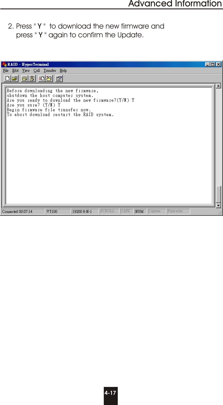
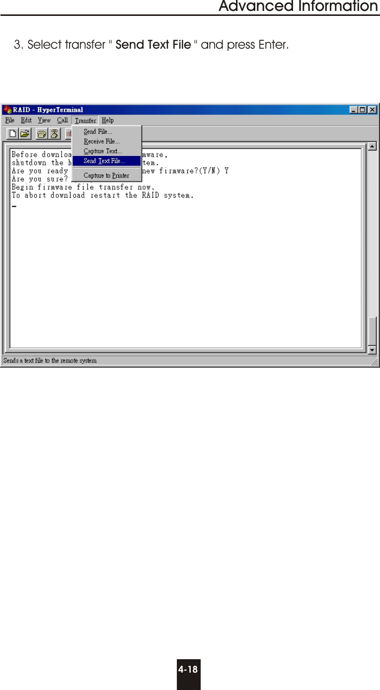
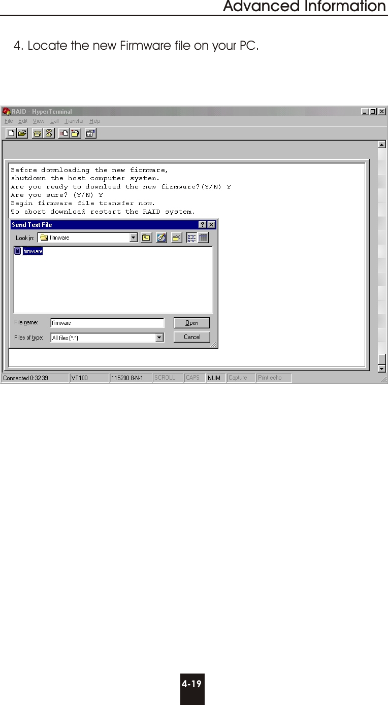
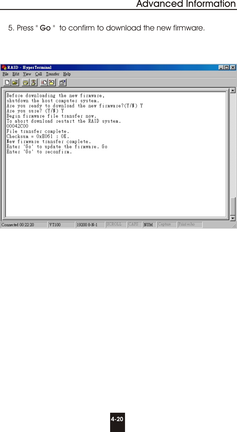
4.
users manual 4
5.
users manual 5
6.
users manual 6
7.
users manual 7
users manual 5
Navigation menu
Upload a User Manual
Namespaces
Wiki Guide
HTML
PDF
Info
Views
User Manual
Discussion / Help
Navigation