Maxtronic Co INDY2600 Disk Array User Manual Indy2600 Ch4
Maxtronic International Co Ltd Disk Array Indy2600 Ch4
Contents
users manual 5

Chapter 4 : " Advanced Information "
This chapter describes more information about your Disk Array. The
following items are describes in detail.
Memory Expansion
RAID Controller
Updating Firmware
Capacity Expansion (On-Line Expand)
4-1
Memory Expansion
Your Disk Array comes with 128MB of memory that is expandable
to a maximum of 512MB.
These expansion memory module can be purchased from your
dealer.
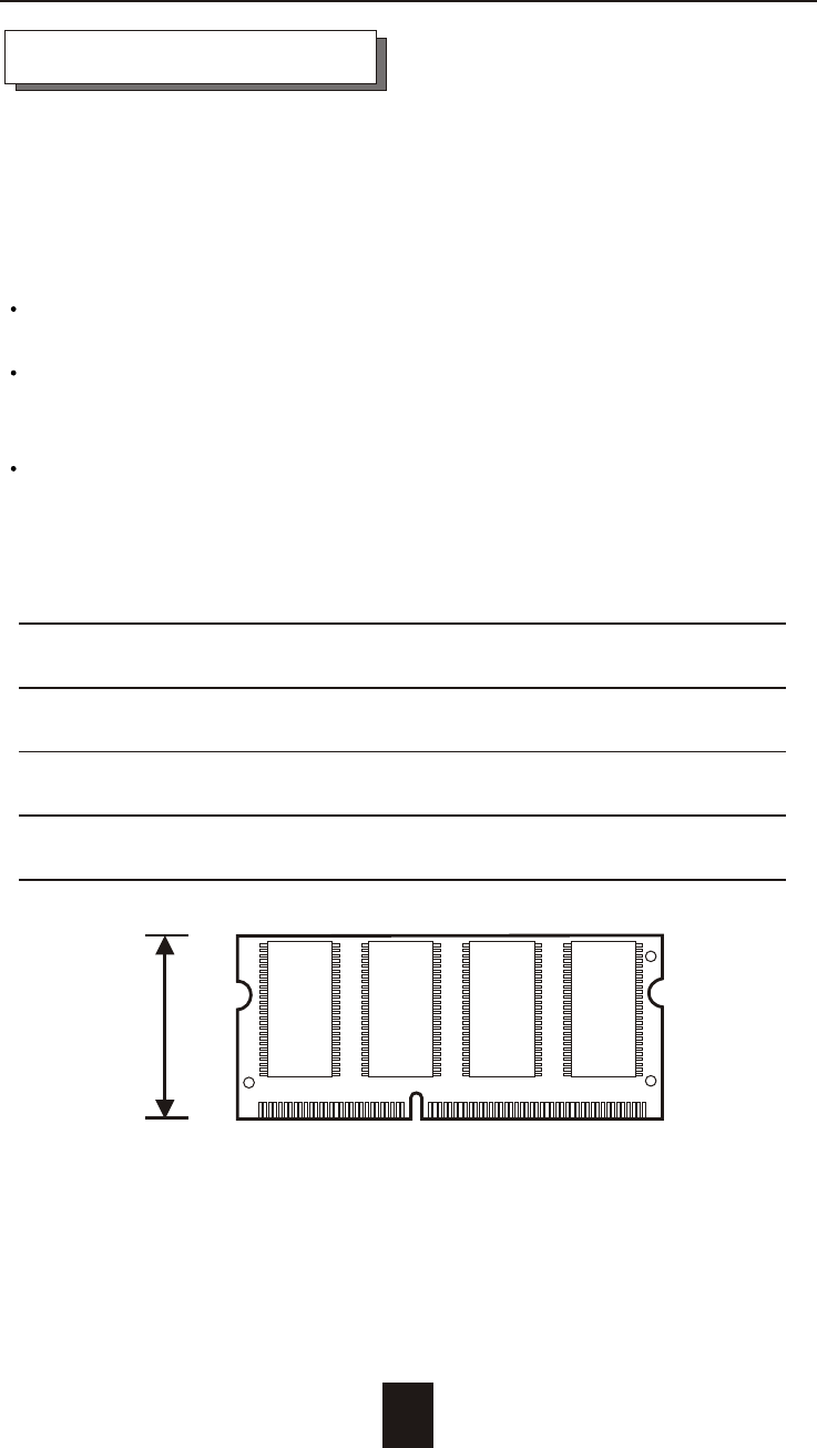
Memory Type : 3.3V PC100/133 SDRAM 144pin DIMM.
Memory Size : Supports 144pin DIMMs of 64MB, 128MB, 256MB
or 512MB.
Height : 1.15 Inches ( 29.2 mm ).
4-2
Advanced Information
64MB 8(8Mx8), 8(4Mx16) or 4(8Mx16)
128MB 16(8Mx8), 8(16Mx8), 8(8Mx16) or 4(16Mx16)
256MB 16(16Mx8), 8(32Mx8) or 8(16Mx16)
512MB 16(32Mx8)
1.15"
(29.2mm)
Installing Memory Module :
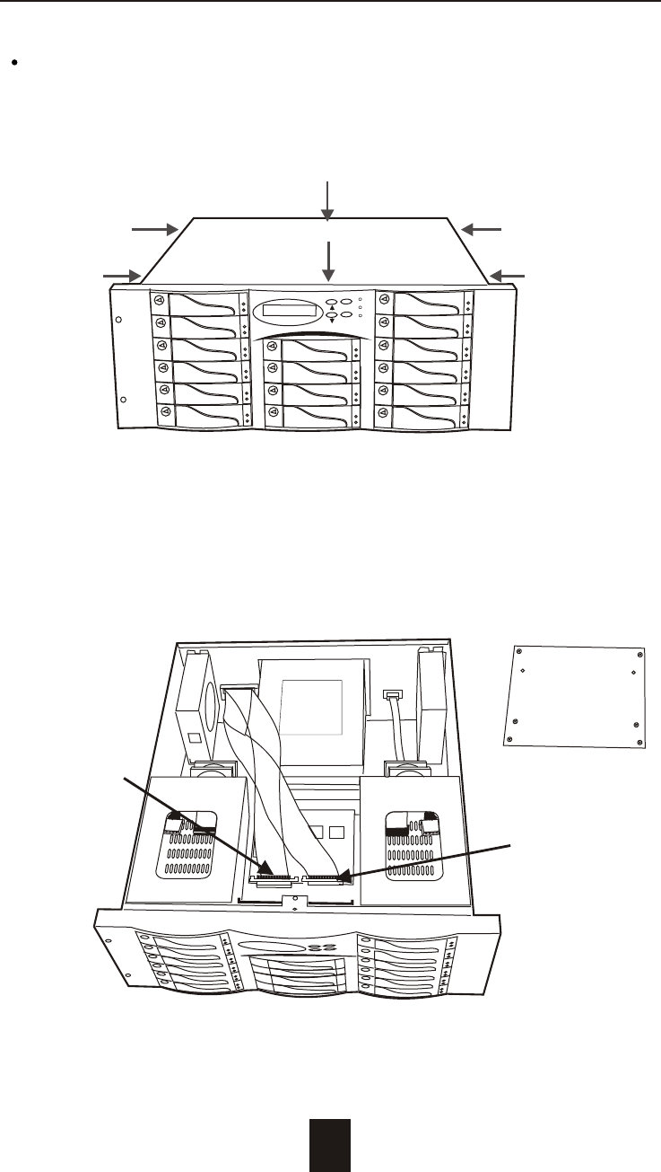
1. Unscrew & Remove cover
4-3
Advanced Information
Figure : Remove Cover
Unscrews
2. Remove the Internal SCSI Host Cable
Figure : Remove SCSI Cable
Internal SCSI
Host 1 Cable
Internal SCSI
Host 2 Cable
ESC
Enter
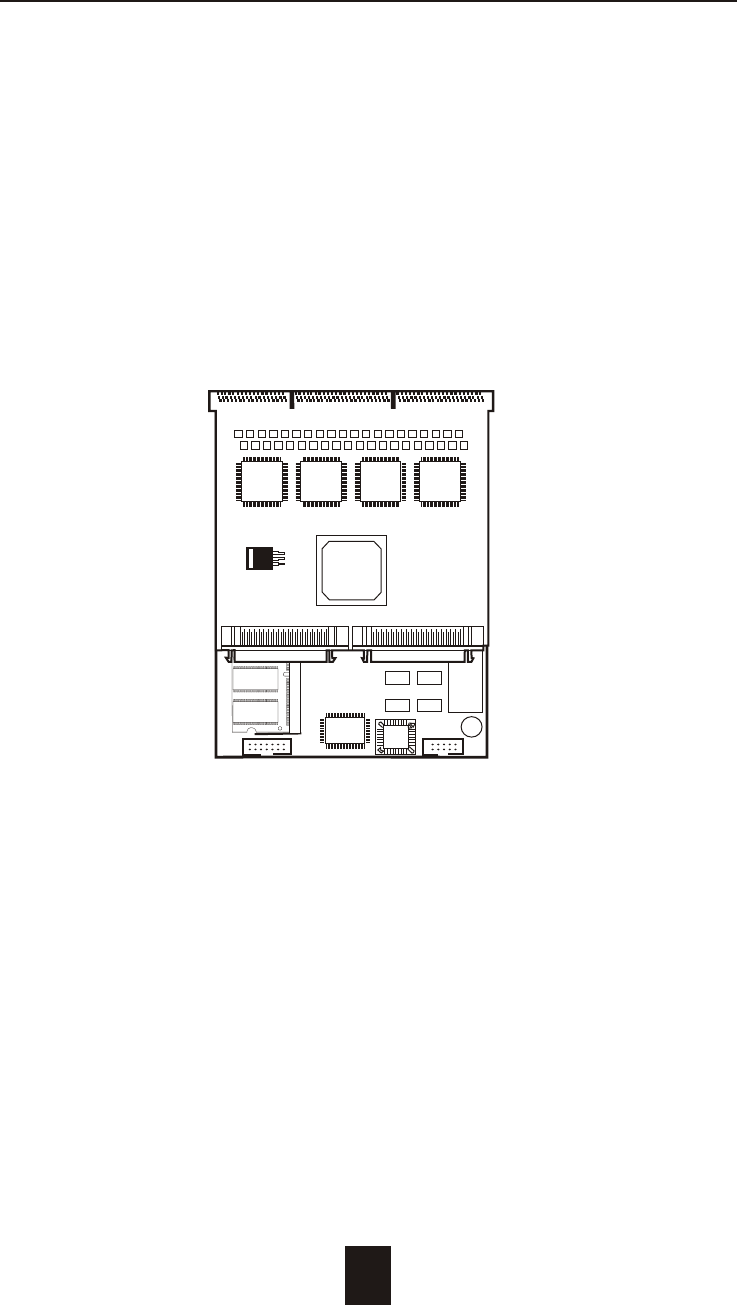
3. Remove the RAID Controller Set
a. Remove the RAID Controller's Holder screws
b. Push the RAID Controller Set toward to the front panel to
release the Controller Set from the Back Panel PCB.
4-4
Advanced Information
Figure : Remove the RAID Controller
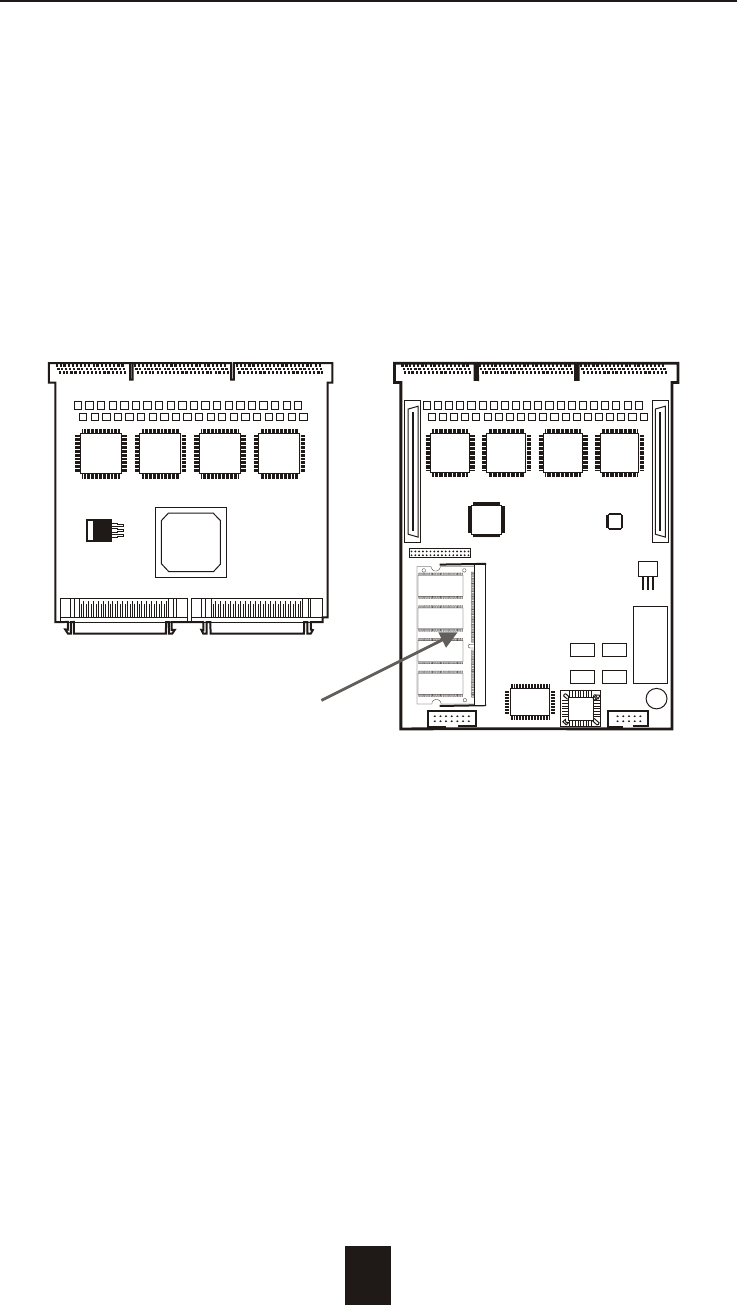
4. Separate the Controller
a. Separated the Controller's main board and the daughter
board.
b. Remove the DIMM Memory from the RAM socket.
4-5
Advanced Information
Figure : Separate RAID Controller
RAM Socket
Daughter Board
Main Board
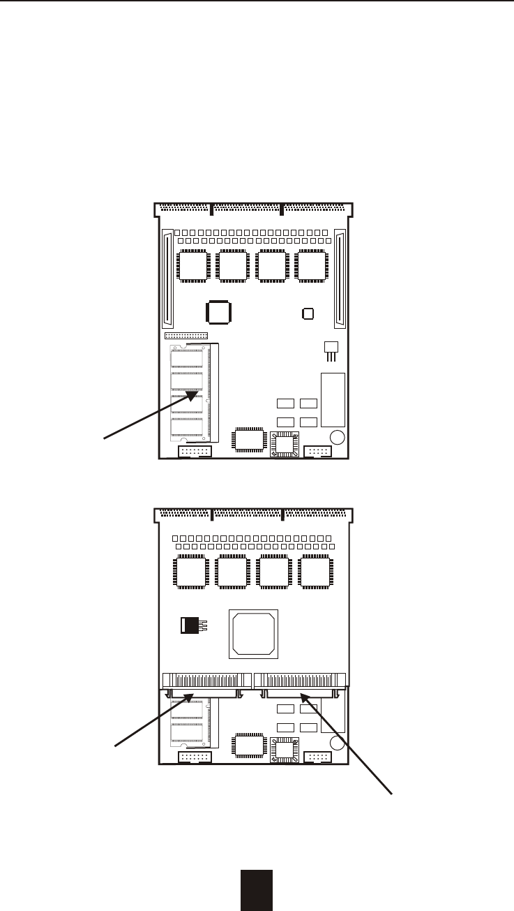
5. Install the memory
a. The DIMM memory modules will only fit in one orientation.
b. Press the memory module firmly into socket from a 45 degree
angle, make sure that all the contacts are aligned with the
socket.
c. Push the memory module forward to a horizontal position.
4-6
Advanced Information
Figure : RAID Controller Host Channel #1
RAM Socket
Main Board
Host Channel #2
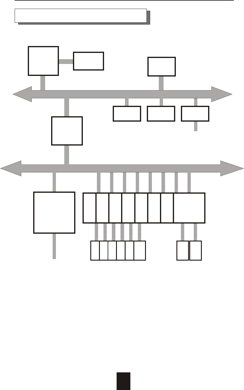
Dual
Host
Channel
NVRAM LCD RS232
Terminal
Port
PCI BUS
i80303 Local BUS
PCI
Bridge
Main
memory
i80303
RISC
Micro-
processor
Flash
EPROM
Disk Array Controller Block Diagram
Advanced Information
4-7
Disk
# 1
Disk
# 2
Disk
# 15
Disk
# 16
Dual
Channel
IDE
Controller
Dual
Ultra 160
Wide
SCSI
controller
Disk
# 3
Disk
# 4
Dual
Channel
IDE
Controller
Dual
Channel
IDE
Controller
Dual
Channel
IDE
Controller
Dual
Channel
IDE
Controller
Dual
Channel
IDE
Controller
Dual
Channel
IDE
Controller
Dual
Channel
IDE
Controller
Disk
# 5
Disk
# 6 ~

4-8
Advanced Information
Updating Firmware
1. Setup your VT100 Terminal
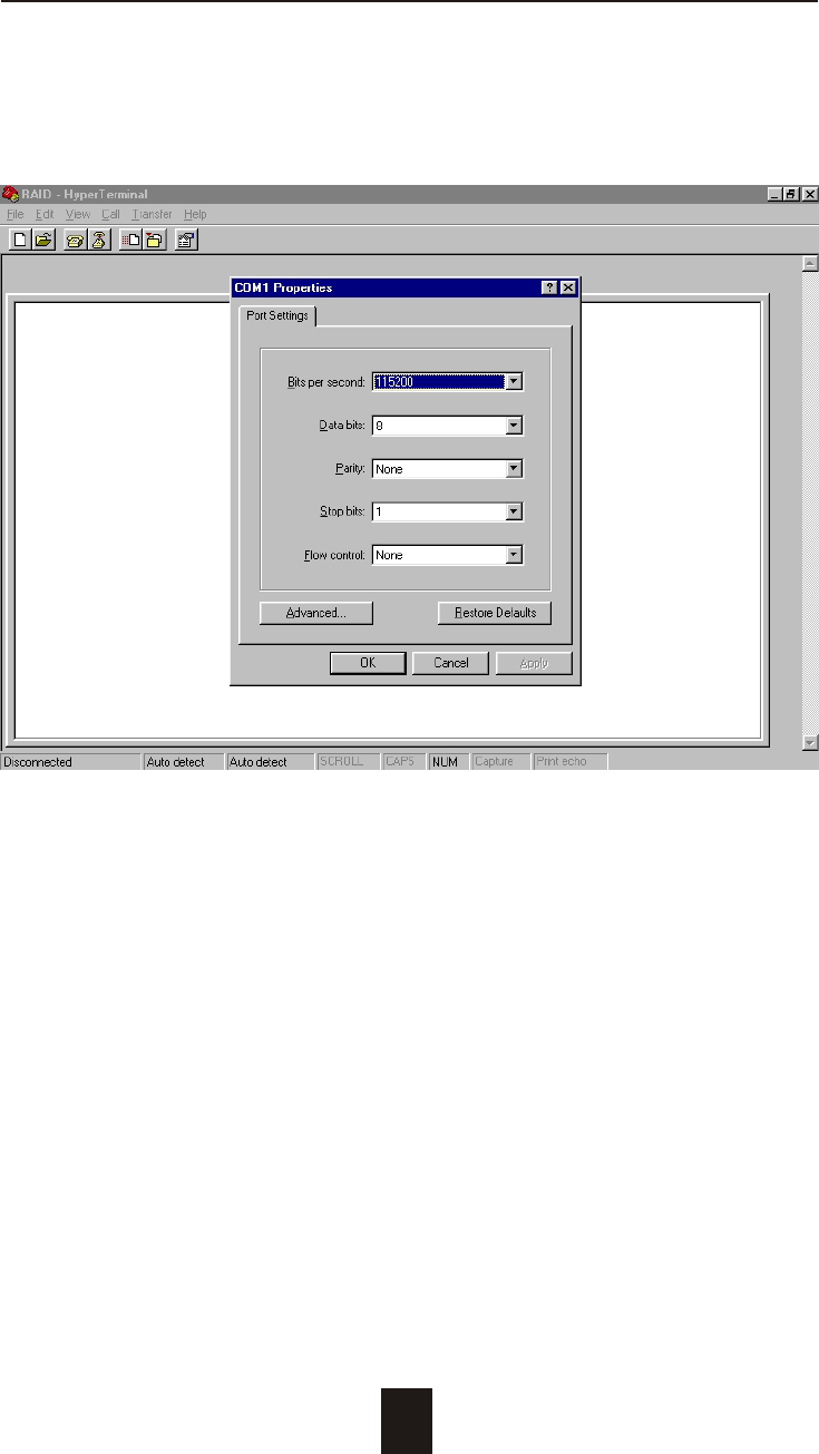
Please configure the VT100 terminal setting to the values shown
below :
VT100 terminal ( or compatible ) set up
Connection Serial Port ( COM1 or COM2 )
Protocol RS232 ( Asynchronous )
Cabling Null-Modem cable
Baud Rate 115,200
Data Bits 8
Stop Bit 1
Parity None
Advanced Information
4-9
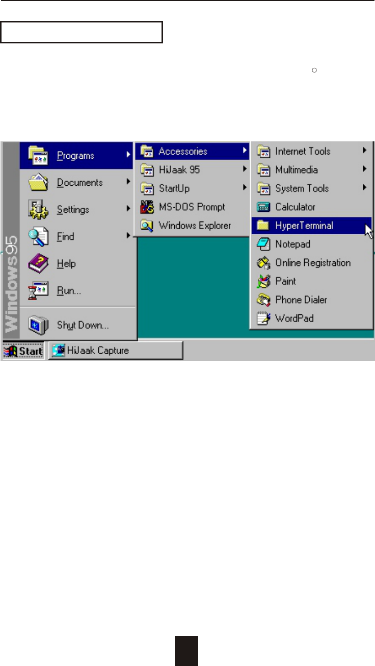
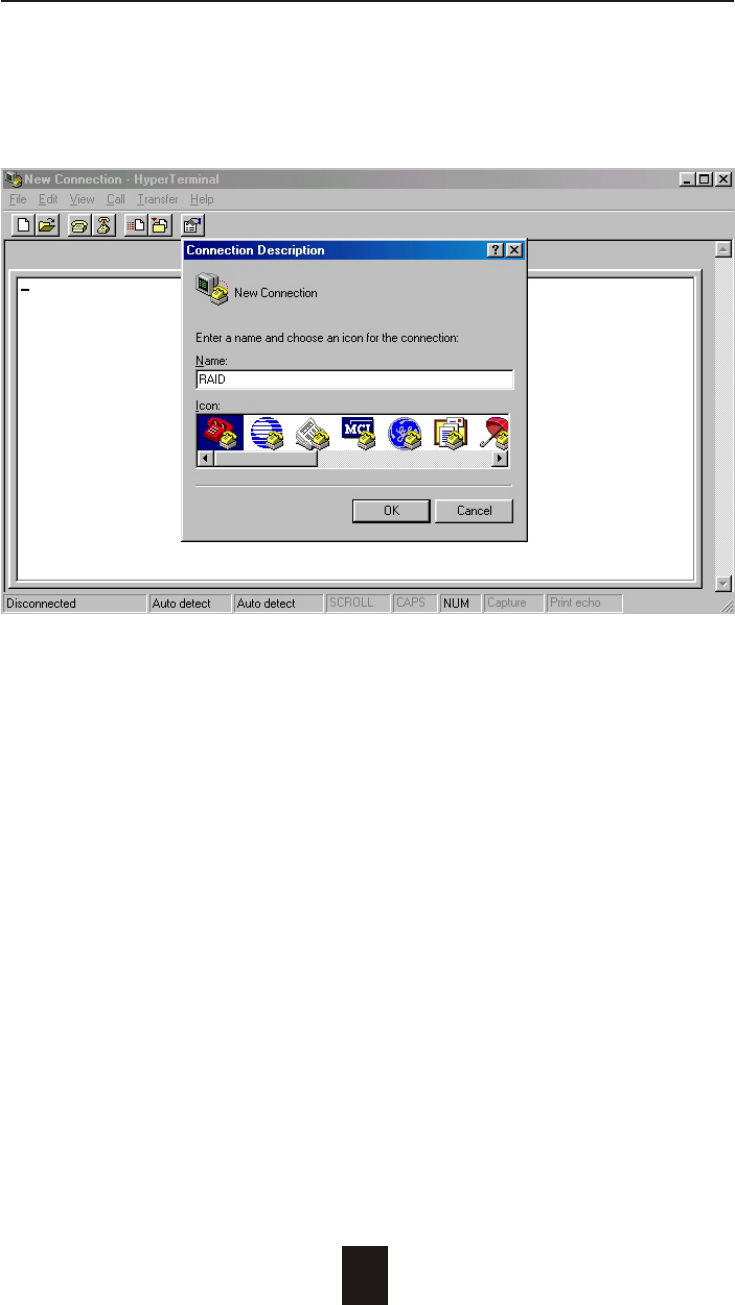
Example : Setup VT100 Terminal in Windows 95
Step 1.
Setup VT100 Terminal
R
Advanced Information
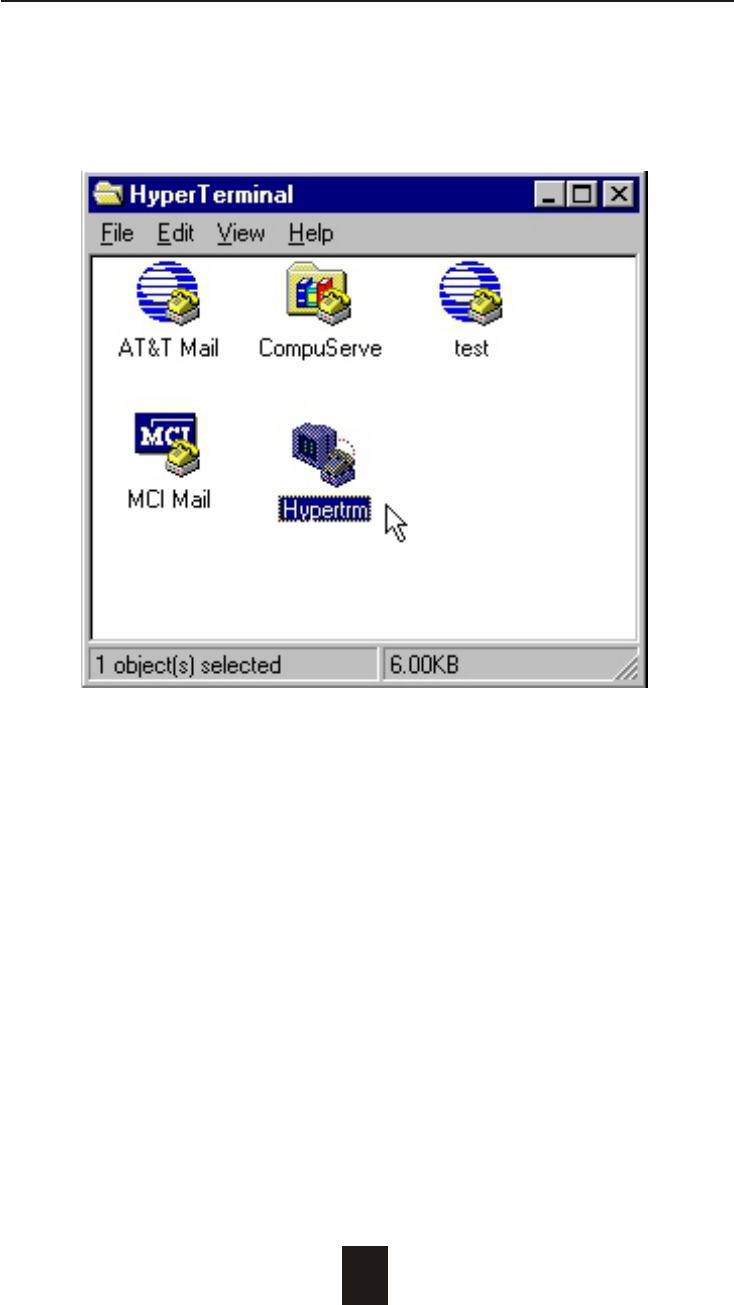
Step 2.
4-10
Advanced Information
Step 3. Enter a name for your Terminal.
4-11
Advanced Information
4-12
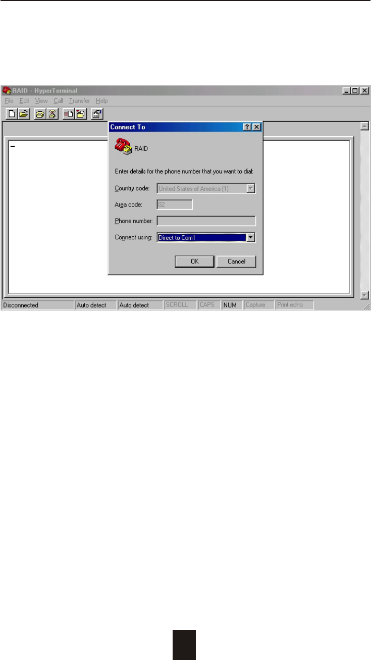
Step 4. Select a connecting port in your Terminal.
Advanced Information
4-13
Step 5. Port parameter settings
Advanced Information
4-14
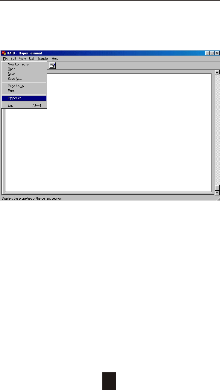
Step 6.
Advanced Information
4-15
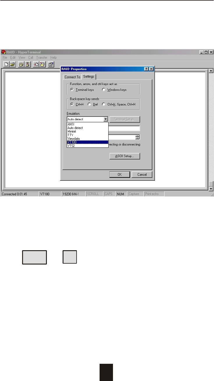
Step 7. Select emulate VT100 mode
After you have finished the VT100 Terminal setup, you may restart
your Disk Array and press " Ctrl + D " keys ( in your Terminal )to link
the Disk Array and Terminal together.
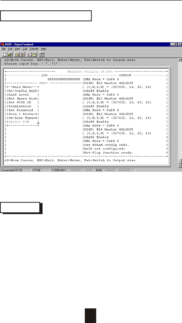
Press Ctrl + D to display the disk array Monitor Utility
screen on your VT100 Terminal.
Advanced Information
4-16
Start to Update Firmware
1. Move the cursor to " Update ROM " and press "Enter".
Warning !
Unpredictable results will occur if firmware update is attempted
during Host computer and Disk Array activity. All activity to the
controller should be stopped before updating firmware.
4-17
Advanced Information
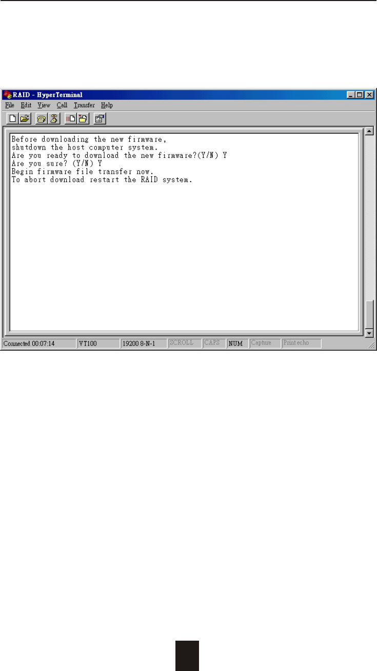
2. Press " Y " to download the new firmware and
press " Y " again to confirm the Update.
4-18
Advanced Information
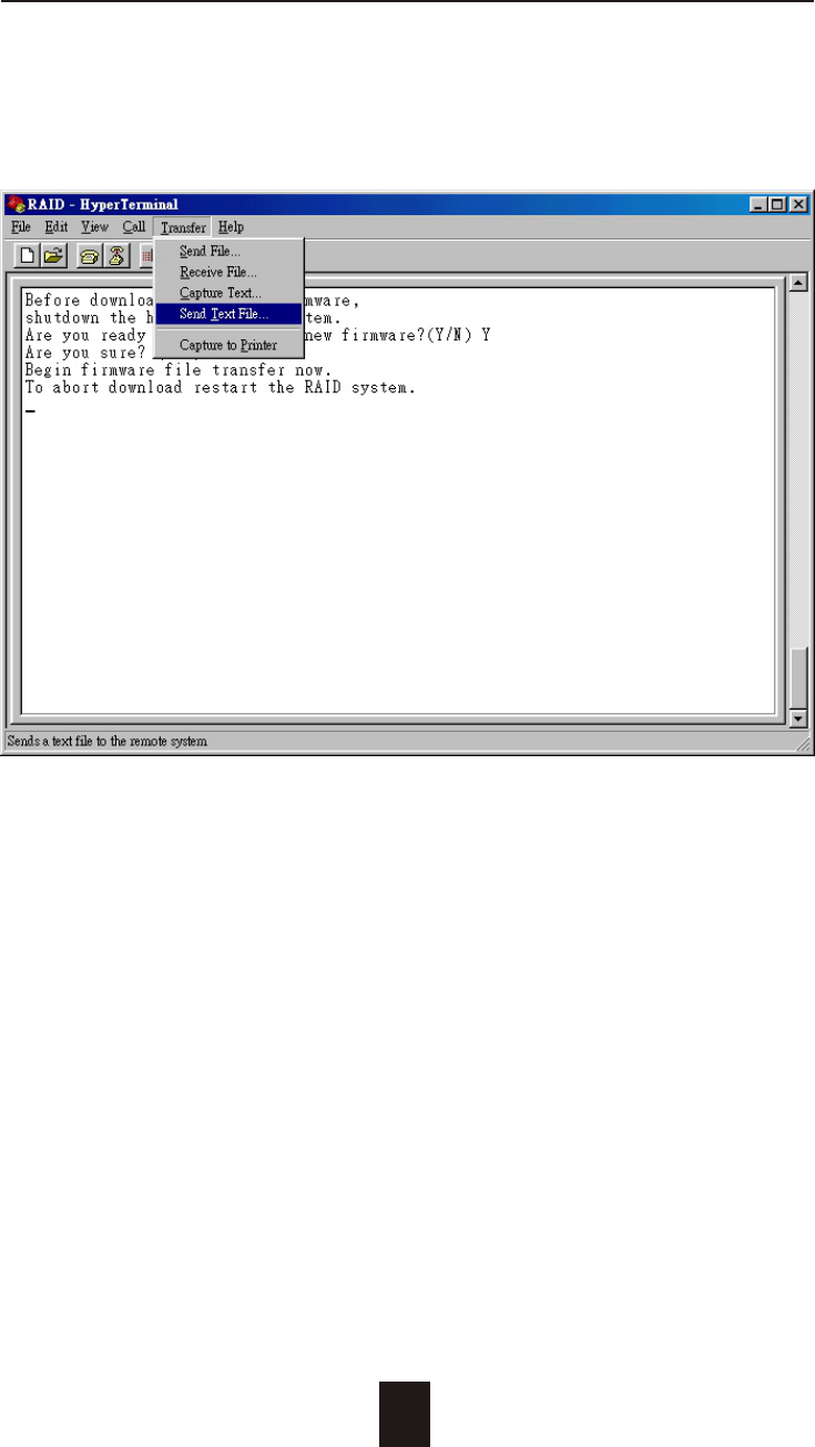
3. Select transfer " Send Text File " and press Enter.
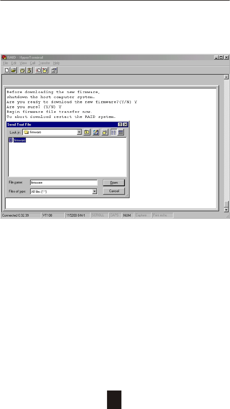
4-19
Advanced Information
4. Locate the new Firmware file on your PC.
4-20
Advanced Information
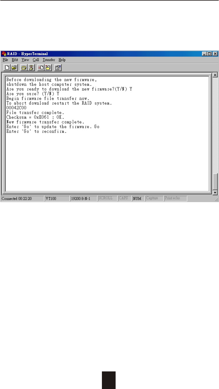
5. Press " Go " to confirm to download the new firmware.
4-21
Advanced Information
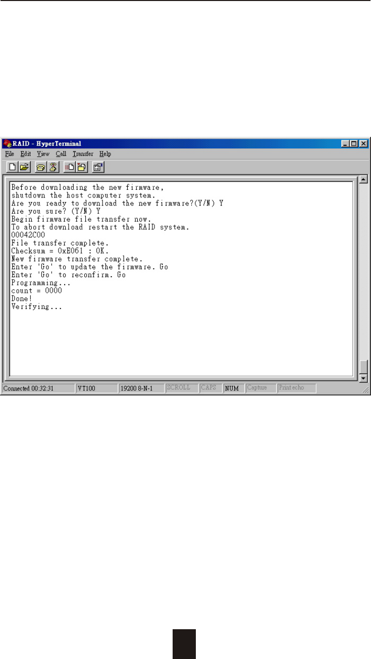
6. Type " Go " to reconfirm and the firmware will begin to be
reprogrammed.
7. After verifying, please Restart the Disk Array to activate the
new firmware.