Maxtronic Co INDY2600 Disk Array User Manual Indy2600 Ch2
Maxtronic International Co Ltd Disk Array Indy2600 Ch2
Contents
users manual 3

Chapter 2 : " Getting Started "
General Overview
This chapter helps you get ready to use the Disk Array. It gives you :
Unpacking & Checklist
Choosing a place for Disk Array
Identifying Parts of Disk Array
Power Source
Installing the Hard Disk Drives
Host Linkage
Power-On and Self-test
LED Display and Function Keys
LCD Status Display
The following illustrations will help you read the further sections.
2-1
Special Note :
RAID should never be considered a replacement for doing
regular backup. It's highly recommended to conduct a
backup strategy for critical data.
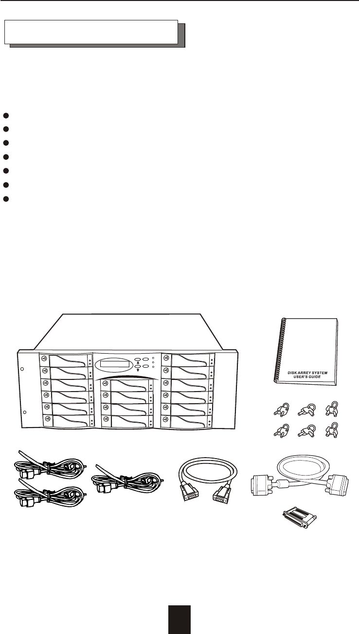
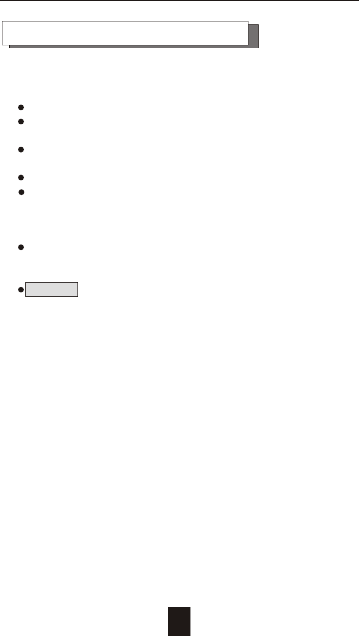
Unpacking & Checklist
Before unpacking your Disk Array , prepare a clean and stable
place to put the contents of your Disk Array's shipping container on.
Altogether, you should find the following items in the package :
The Disk Array
AC power cord
One External SCSI cable
Keys ( For HDD Trays )
User Guide
RS-232 Cable
Active Terminator
Remove all the items from the carton. If anything is missing or
broken , please inform your dealer immediately.
Save the cartons and packing materials that came with the Disk
Array. Use these materials for shipping or transporting the Disk Array.
2-2
Getting Started
Figure : Checklist
L
VD/SE
ESC
Enter
Choosing a place for Disk Array
When selecting a place to set up your Disk Array, be sure to follow
the guidelines as below:
Place on a flat and stable surface.
Use a stand that supports at least 50 kgs for this Disk Array.
(HDD included )
Place the Disk Array close enough to the computer for the Disk
Array's External SCSI cable to reach it.
Use a grounded wall outlet.
Avoid an electrical outlet controlled by wall switches or
automatic timers. Accidental disruption of the power source
may wipe out data in the memory of your computer or Disk
Array.
Keep the entire system away from potential sources of
electromagnetic interference, such as loudspeakers , cordless
telephones, etc.
Caution !
Avoid direct sunlight, excessive heat, moisture, or dust.
2-3
Getting Started
2-4
1
Getting Started
3
98
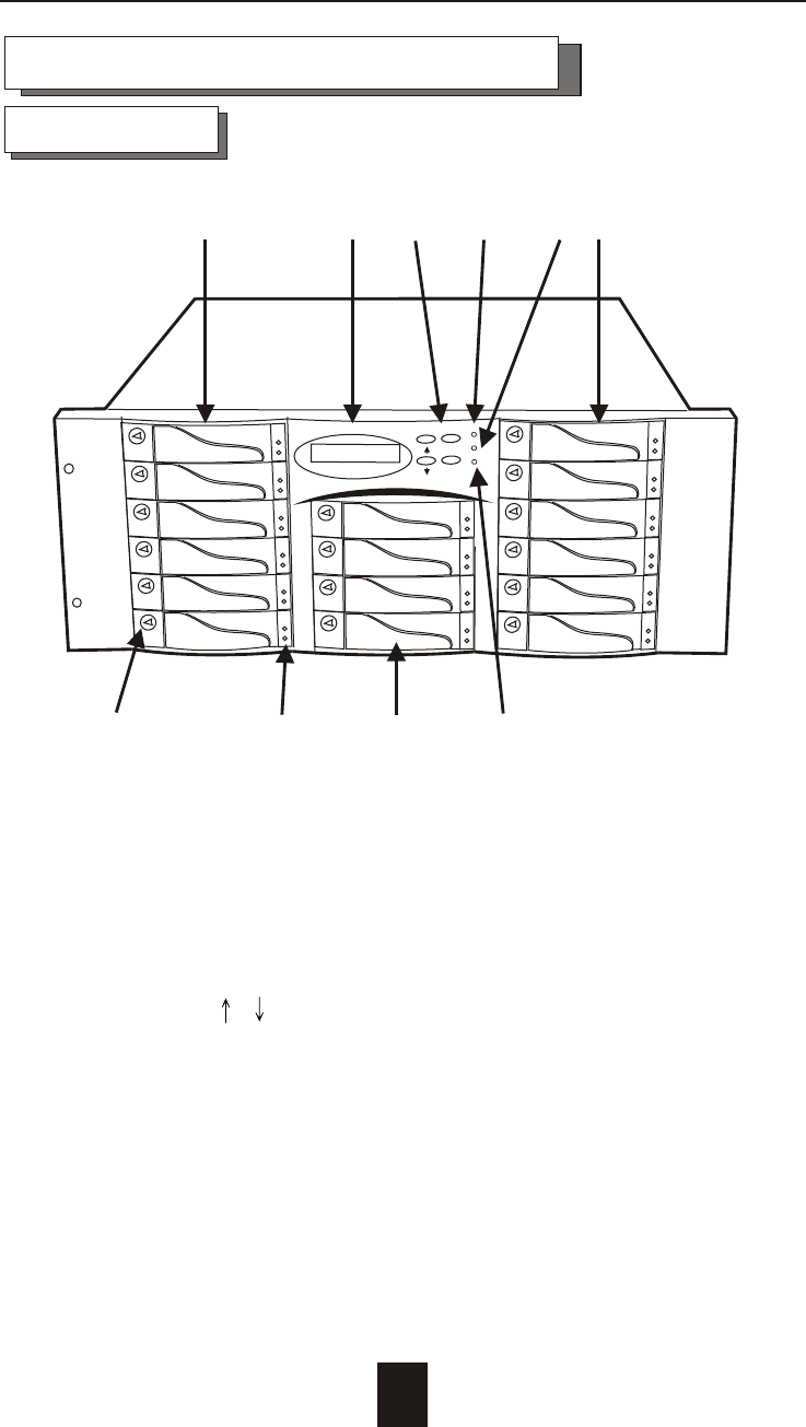
Front View
Identifying Parts of the Disk Array
Figure : Front View
1. LCD Status Display Panel
2. HDD Trays 1 ~ 6 (From Up to Down)
3. HDD Trays 7 & 10
4. HDD Trays 11 ~16
5. Function Keys ( , , Enter , ESC )
6. Power-On Indicator ( Green )
7. Power Fail Indicator ( Red )
8. Host Computer Access Indicator ( Yellow )
9. HDD Tray Lock ( Lock / Unlock )
10. HDD Status Indicator
( Error (Red), Access (Yellow), Power-On (Green))
2 4
10
57
ESC
Enter
6
2-5
Getting Started
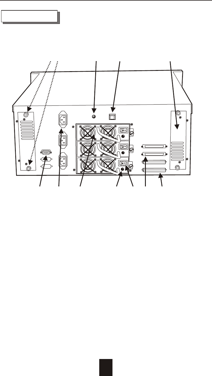
REAR VIEW
Figure : Rear View
1. RS-232 Adapter (Terminal Port)
2. AC Power Input Sockets #1~3 ( from up to down )
3. Power Supply Unit #1~3 ( from up to down )
4. Power Supply "Power-On" Indicator (Green)
5. Power Supply Unit On / Off Switch (0 / I)
6. SCSI Channel Port ------ ( Host 1 )
7. SCSI Channel Port ------ ( Host 2 )
8. Cooling Fan
9. Power Supply "Alarm" Reset Button
10. Power Supply Fail Indicator (Red)
11. Cooling Fan Screws
2 3
1
65
8
9
10
4
11
7
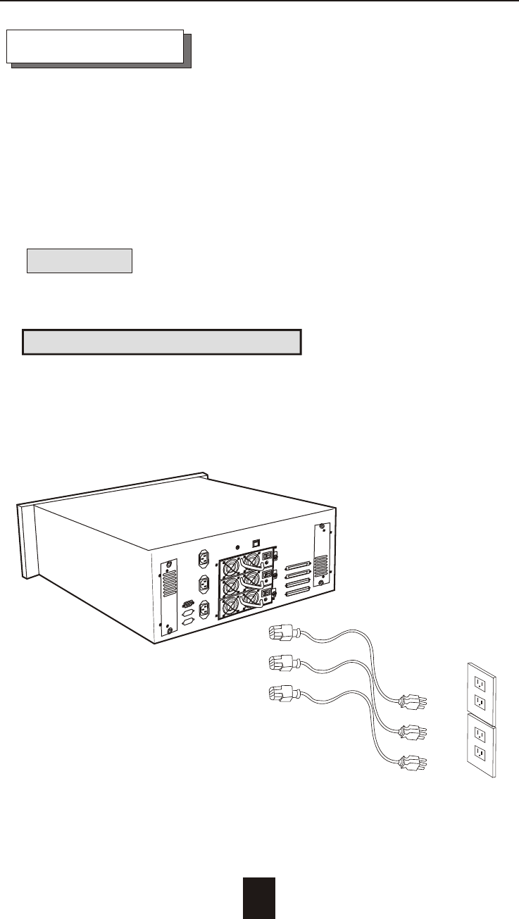
Power Source
Working Voltage
The system can run either on AC 115V (+/10%) or AC 230V
(+/10%) environment.
The system's power supply provide full range AC electricity input
from AC 90Volt to 260Volt.
Warning !
Wrong AC Voltage input will harm the power supply and
cause serious damage to the Disk Array.
This Disk Array is supplied with an AC power cord equipped with
a 3-wire grounding type plug. This is a safety feature and it is
important to only use a 3-wire grounded mains power cord.
! This Disk Array must be grounded
2-6
Getting Started
Figure : Power Source
2-7
Getting Started
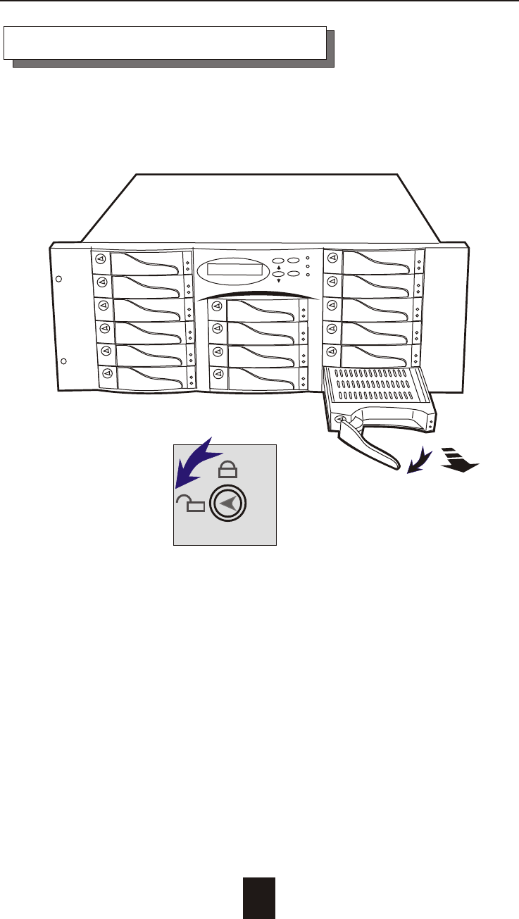
Figure : Installing HDD step 1, 2
Installing the Hard Disk Drives
Step 1 : Unlock the HDD tray by turning the Key-lock to the
correct position.
Step 2 : Gently Pull out the HDD tray.
ESC
Enter
Getting Started
2-8
SCREWS
SCREWS
Cabling
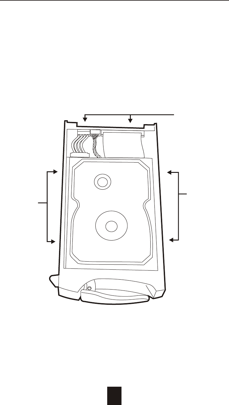
Figure : Installing HDD step 3, 4, 5
Step 3 : Insert HDD into the tray
Step 4 : Screw in the hard drive.
( Use the correct size, type and thread )
Step 5 : Cabling, Connect the Data cable and Power cable.
Getting Started
2-9
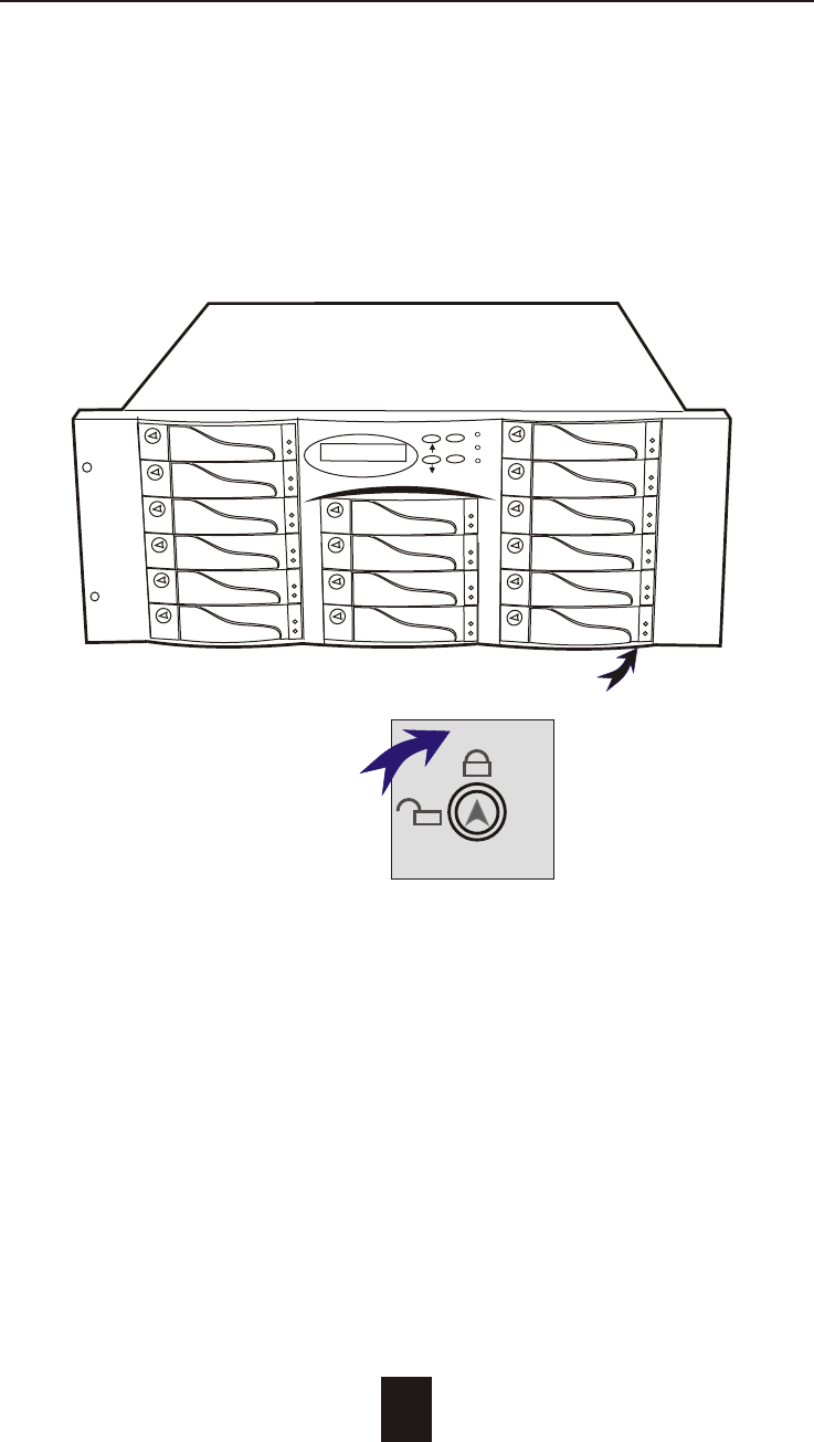
Figure : Installing HDD step 6, 7
Step 6 : Gently slide in the HDD tray.
Step 7 : Lock the HDD tray. When powered on, the Green LED
will light up.
ESC
Enter
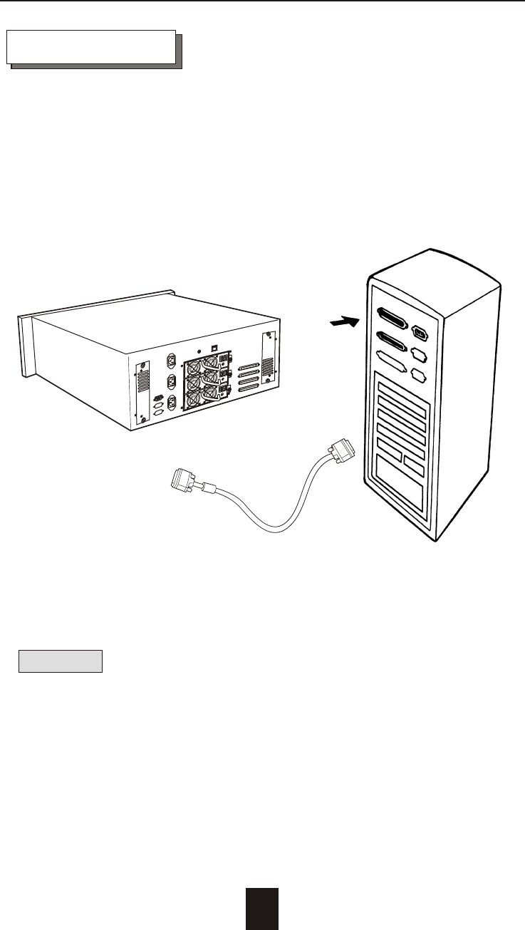
Host Linkage
With the HDD(s) installed correctly, you are ready to connect the
Disk Array to your Host computer.
Use a shielded twisted-pair SCSI cable to connect your Host
computer to the Disk Array's built-in 68 pin SCSI adapter port.
Connect the Host computer as shown below :
Figure : Host linkage
Caution !
For safety reasons, make sure the Disk Array and Host Computer
are turned off when you plug-in the SCSI cable.
2-10
Getting Started
Disk Array
Host Computer
SCSI
Plug
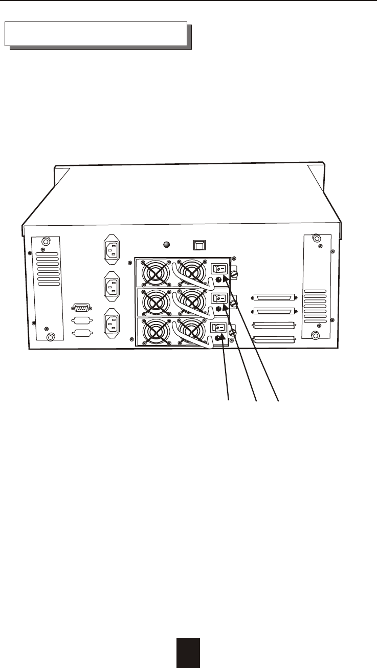
Power-On and Self-Test
When you connect the Disk Array to the Host computer, You
should press the ON/OFF Switch ( o / I ) on all of the power
supply Hot-Swap units and It will turn the Disk Array on and the
Self-Test will be started automatically.
2-11
Getting Started
Power Supply Unit's On / Off Switch
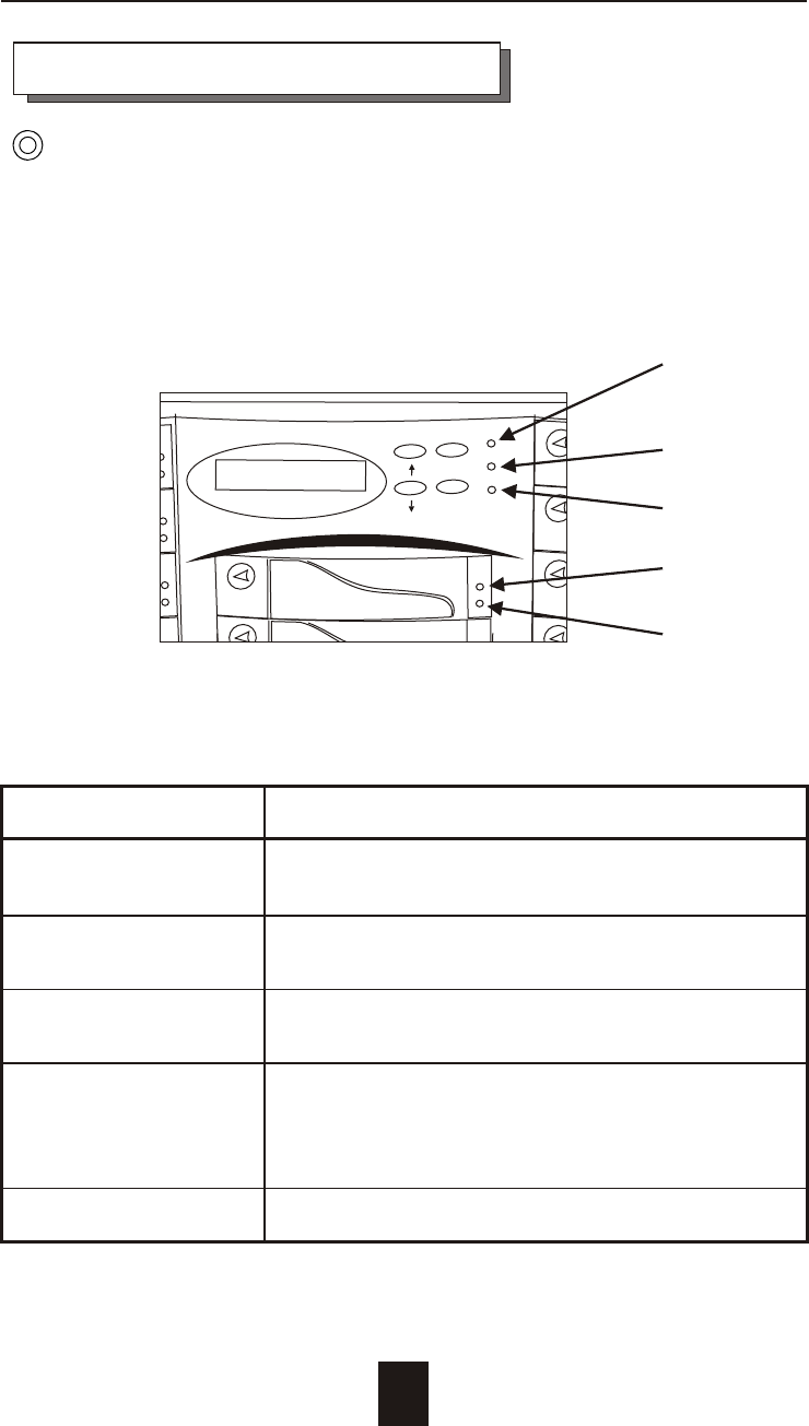
LED Descriptions
1. Power On Indicator light up : "Green" , it lights when the Power source
is plugged and system is on.
2. P/S Fail Indicator light up : "Red" , it lights when any one of the Power Unit
(Power Supply Fail) failed.
3. Host Computer Access light up : "Yellow" , Indicates Host
Indicator computer is currently accessing the Disk Array
4. HDD Power-On Indicator light up : "Green" , It lights when the HDD tray
is locked and Power-On
HDD Error Indicator light up : "Red" , when the HDD not installed or error.
5. HDD Access Indicator light up : "Yellow" , when HDD is accessed
2-12
1
2
3
Getting Started
LED Display & Function Keys
LED Display
Shown below is the LED Display. Please refer to the illustration,
the LEDs inform you of the Disk Array's current operating status.
Upon activating a certain function, the corresponding LED
indicator should turn on indicating that the feature is engaged.
Figure : LED Display
ESC
Enter
Power
P/S Fail
Access
4
5

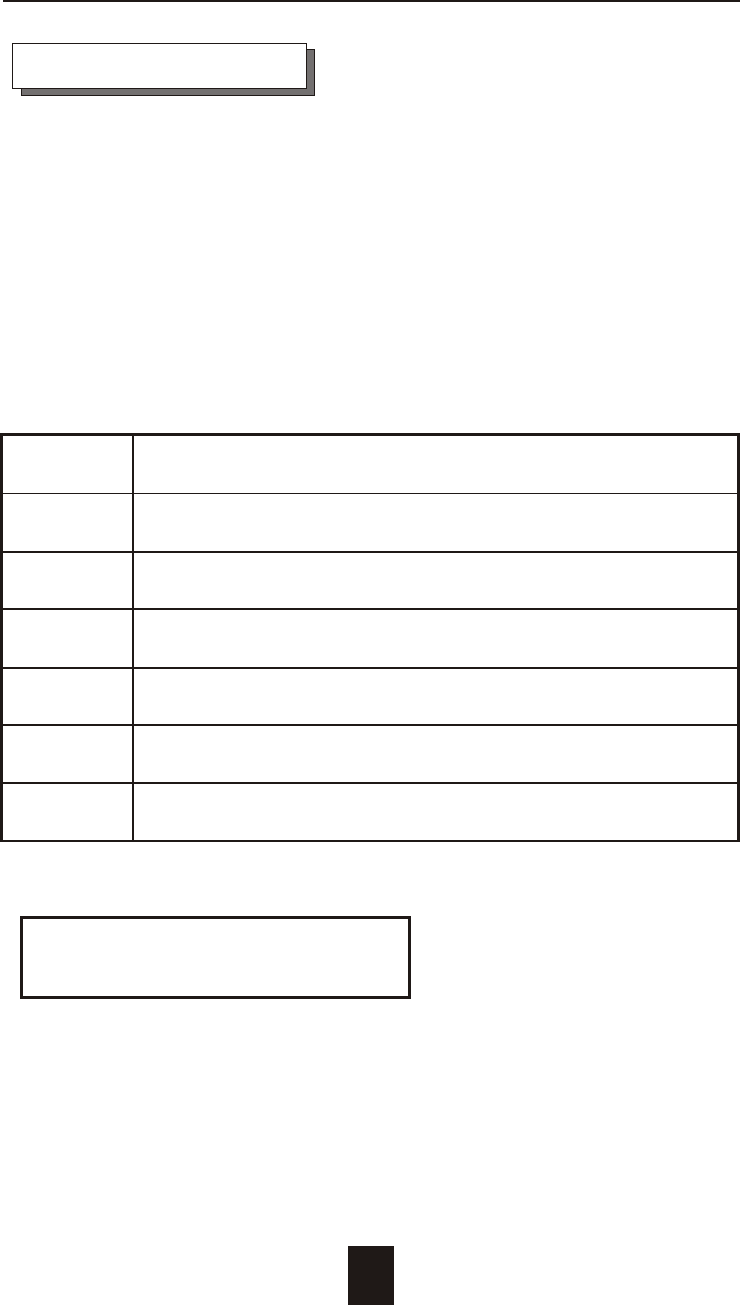
Function Keys
The four function keys at the top of the front panel perform the
following functions :
( ) Up Arrow / Right Arrow Use to scroll the cursor Upward / Rightward
( ) Down Arrow / Left Arrow Use to scroll the cursor Downward / Leftward
( Enter ) Use to confirm a selected item
( ESC ) Use to exit a selection
2-13
Getting Started
LCD Status Panel
Located the LCD panel, the LCD status panel informs you of the
Disk Array's current operating status at a glance. Upon activating
a certain function, a symbol or icon corresponding to that
function will appear in the display window. The symbol will remain
in the display window indicating the status of the Disk Array.
Identifying the status on the LCD
The following illustration shows the symbols (characters) been
used and their representation.
A description of each of the symbols in LCD display window :
O On-line and functional
R Error occur (Fault)
I Identifying Disk Drive
S Spare Disk Drive
X Disk Drive not installed
W Warning : Disk Drive with too many Bad Sectors
A Add new Disk Drive when On-Line Expansion
Example of the LCD status display window :
OOOOOOOOOOOOSSXX
This informs you :
a. HDD 1 ~ HDD 12 : On-line
b. HDD 13&14 : Hot-Spare disk drive
c. HDD 15&16 : Not installed
2-14
Getting Started