Maxtronic Co INDY2600 Disk Array User Manual Indy2600 Ch1
Maxtronic International Co Ltd Disk Array Indy2600 Ch1
Contents
users manual 2

This chapter will introduce you to your new Disk Array's features and
provide information on general RAID concept.
Chapter 1 : " Introduction "
1-1

1-2
Introduction
Features
This section provides an overview of the features. For more detailed
information, please refer to the technical specifications appendix
at the end of this manual .
Your Disk Array includes the following features :
Easy Operation
As everyone knows, conventional Disk Arrays are designed for
experienced computer specialists. To solve complicated and time
consuming operating procedures, we came up with a revolutionary
idea :
-- Innovative Plug And Play RAID --
As compared to a conventional Disk Array's long-winded setup
procedures, your Disk Array can be ready to go after using the
simple step by step built-in setup program.
Ultra High performance
Your Disk Array combines an extremely high speed microprocessor
with the latest chip set, SCSI hardware technology, perfect firmware
and an artistic design. The result is one of the fastest, most reliable
Disk Array systems on the market.
Supports virtually all popular operating systems ,platforms and
network environments because it works independently from the
O.S.
Ultra 160 LVD SCSI channel interface to your Host computer, up to
160MB data transfer rate provides the processing and access
power for you to handle complex and large files.
Selective SCSI ID 0 ~ 14 , support with active termination.
Tagged-command queuing : allows processing of up to 255
simultaneous data requests.
Selective RAID levels 0, 1, 0+1, 3 or 5.
Build-in 128MB cache memory, expandable up to 512MB.
Serial communication port ( Terminal Port ) permits array controller
operation through a standard VT100 terminal (or equivalent).

1-3
Introduction
Solid reliability
Automatic failed disk drive detection.
Auto rebuild : when a replacement disk installed (or by using hot
spare disk ), The system provides automatic data rebuild without
any commands or functions keyed in. ( Transparent to Host )
Efficient maintenance
An LCD status panel displays a comprehensive readout of the
operating status, and the HDD LED indicators on each HDD tray
display the individual HDD status.
When disk failure occurs on a member disk of the disk array, the
built-in buzzer sounds simultaneously and LCD status panel
also points out the location of the failed hard disk drive. In the
meantime the LED HDD status indicator will light up " Red "on the
failed HDD tray , according the LED indicator on the HDD tray you
can perform quick, efficient and correct maintenance.
Hot Swap : allows you can remove and install the " Hot Swap "
parts without interrupting data access while the system is on.
The " Hot Swap " parts include the Hard Disk Drive, Redundant
Power Supply Unit and Cooling Fan.

1-4
Introduction
General RAID Concepts
Correct installation of the disk array requires an understanding of
RAID technology and the concepts described in this section.
Definition
RAID is an acronym of Redundant Array of Independent Disks .
A RAID is a Disk Array in which part of the storage capacity is used to
record redundant information about the user data stored on the
remainder of the storage capacity. The redundant information
enables regeneration of user data in the event that one of the
Array's member Disks or the access path to it fails.
Benefits of RAID
1. Secure Data
RAID is an emerging storage technology with the potential to
revolutionize the data storage technology. A typical RAID unit
contains a set of disk drives, typically two to six, which appear to
the user to be equivalent to a single large capacity disk drive. The
remarkable benefit of disk array is that if any single disk in the RAID
fails, the system and array still continues to function without loss of
data. This is possible because the redundancy data is stored on
separate disk drives and the RAID can reconstruct the data that
was stored on the failed disk drive.
2. Increases system performance
As the effective seek time for finding data on a disk can
potentially be reduced by allowing multiple simultaneous access
of different data on different disks. Utilizing parallel reads and
writes of the data spread across the disks in the array, the data
transfer rate can be increased significantly over that of a single
disk.
3. Easy maintenance
RAID system maintenance is typically simplified because it is easy
to replace individual disks and other components while the
system continues to function. ( Hot swap support )
4
10
4
10
4
10
4
10
4
10
1-5
Introduction
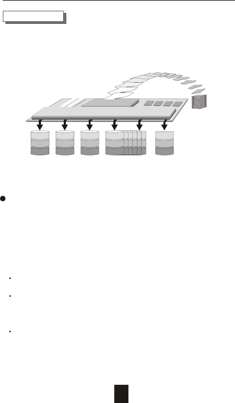
Disk 1 Disk 2 Disk 3 Disk 4~15 Disk 16 Physical
1
17
2
18
3
19
4
20
16
32
Data
1
2
3
4 56789
10
11
12
Disk Array Controller
Array Management Software
Provides Logical to Physical Mapping
Improved I/O performance is the major reason for using RAID level 0.
No protection is provided against data loss due to member disk
failures. A RAID level 0 array by itself is thus an unsuitable storage
medium for data that can not easily be reproduced, or for data that
must be available for critical system operation. It is more suitable for
data that can be reproduced or is replicated on other media.
A RAID level 0 array can be particularly useful for :
Storing program image libraries or runtime libraries for rapid
loading, these libraries are normally read only.
Storing large tables or other structures of read only data for rapid
application access. Like program images, the data should be
backed up on highly reliable media, from which it can be
recreated in the event of a failure.
Collecting data from external sources at very high data transfer
rates.
RAID Level 0 : " Disk Striping " High I/O Performance
RAID Levels

1-6
Introduction
RAID level 0 arrays are not particularly suitable for :
Applications which make sequential requests for small amount of
data. These applications will spend most of their I/O time waiting
for disks to spin, whether or not they use striped arrays as storage
media.
Applications which make synchronous random requests for small
amounts of data.
1-7
Introduction
RAID level 1 provides both very high data reliability and continued
data availability in the event of a failure of an array member. When
a RAID level 1 member disk fails, array management software simply
directs all application requests to the surviving member.
RAID level 1 is suitable for data for which reliability requirements are
extremely high, or for data to which high performance access is
required, and for which the cost of storage is a secondary issue.
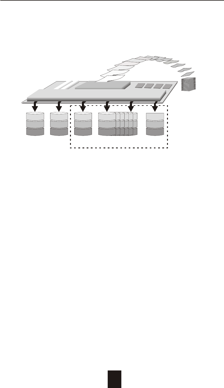
RAID Level 1 : " Disk Mirroring " High Data reliability
Disk 1 Disk 2 Disk 3 Disk 4~15 Disk 16 Physical
1
2
3
1
2
3
1
2
3
1
2
3
1
2
3
Data
1
2
3
4 56789
10
11
12
Disk Array Controller
Array Management Software
Provides Logical to Physical Mapping
Optional
1-8
Introduction
RAID Level 3 technology use a dedicated parity disk to store
redundant information about the data on several data disks.
RAID Level 3 is an excellent choice for applications which require
single stream I/O with a high data transfer rate.
RAID Level 3 is optimal for applications in which large block of
sequential data must be transferred quickly, these applications are
usually of one of these types :
They operate on large data objects such as graphical image
processing, CAD/CAM files, and others.
They are non-interactive applications that process large data
sequentially.
They usually request a large amount of data (32KBytes or more) with
each I/O request.
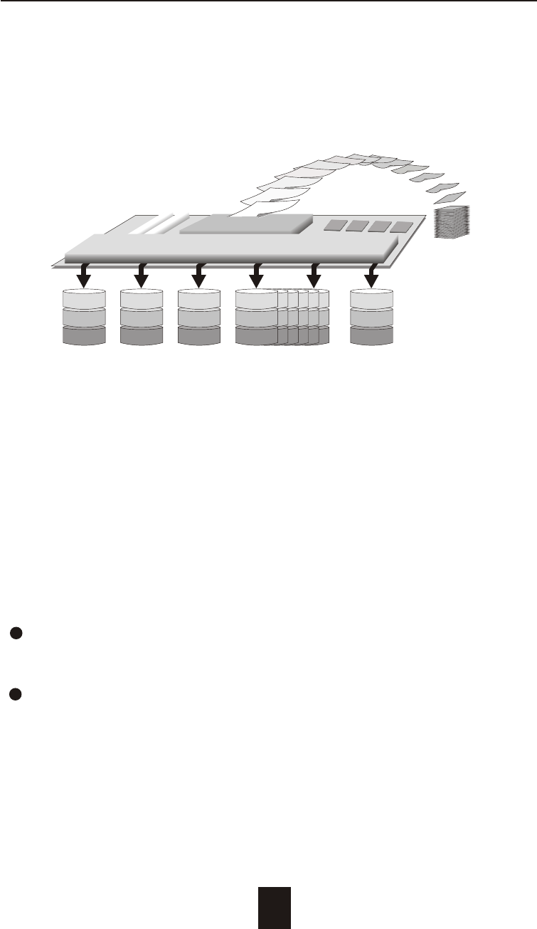
RAID Level 3 :
" Parallel Transfer Disks with Parity "
High Data Reliability & Highest Transfer Capacity
Disk 1 Disk 2 Disk 3 Disk 4~15 Disk 16 Physical
1
16
31
2
17
32
3
18
33
4
19
34
P
P
P
Data
1
2
3
4 56789
10
11
12
Disk Array Controller
Array Management Software
Provides Logical to Physical Mapping
P : Parity

1-9
Introduction
The distinctive performance characteristics of RAID Level 3 :
RAID Level 3 provides excellent performance for data
transfer-intensive applications.
RAID level 3 in not well suited for transaction processing or other
I/O request-intensive applications.
2
7
12
2
7
12
2
7
12
2
7
12
2
7
12
Introduction
When RAID Level 5 technology is combined with cache memory to
improve its write performance, the result can be used in any
applications where general purpose disks would be suitable.
For read only or read mostly application I/O loads, RAID Level 5
performance should approximate that of a RAID Level 0 array. In
fact, for a given user capacity, RAID Level 5 read performance
should normally be slightly better because requests are spread
across one more members than they would be in a RAID Level 0
array of equivalent usable capacity.
A RAID level 5 array performs best in applications where data and
I/O load characteristics match their capabilities :
Data whose enhanced availability is worth protecting, but for
which the value of full disk mirroring is questionable.
High read request rates.
Small percentage of writes in I/O load.
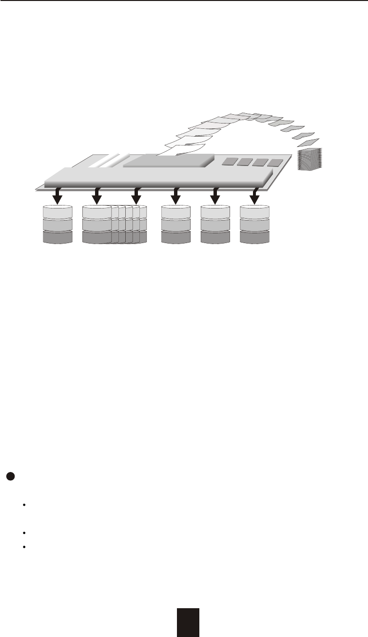
RAID Level 5 :
" Independent Access Array with Rotating Parity "
High Data Reliability & Transfer Capacity
Disk 1 Disk 2~13 Disk 14 Disk 15 Disk 16 Physical
1
16
31
2
17
32
14
29
P
15
P
44
P
30
45
Data
1
2
3
4 56789
10
11
12
Disk Array Controller
Array Management Software
Provides Logical to Physical Mapping
P : Parity
1-10

Introduction
RAID level 5 arrays have unique performance characteristics :
The data can be recalculated or regenerated, using parity,
when any drive in the array fails.
When the failed drive is replaced, either automatically if the
subsystem contained a hot spare drive, or by user intervention
during a scheduled maintenance period, the system will be
restored its full data redundancy configuration by rebuilding all
of the data that had been stored on the failed drive onto the
new drive. This is accomplished using parity information and
data from the other data disks. Once the rebuild process is
complete, all data is again protected from loss due to any
failure of a single disk drive.
1-11
Introduction
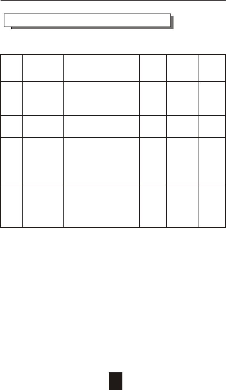
Summary Comparison of RAID Levels
Data
RAID Common Description Array's Data
Transfer
Level Name Capacity Reliability
Capacity
Data distributed across the
0 Disk disks in the array. ( N ) Low Very
S
t r ip
i n
g
No redundant Information disks High
provided.
Ver y
1 Mirroring All data Duplicated 1*disks High
High
3 Parallel Data sector is subdivided ( N-1 ) Very Highest
Transfer and distributed across all disks High of all
Disks with data disk. Redundant listed
Parity information stored on a alter-
dedicated parity disk. natives
5 Independent Data sectors are distributed ( N-1 ) Very Very
Access Array as with disk striping, disks High High
with Rotating redundant Information is
Parity interspersed with user data.
1-12
Introduction
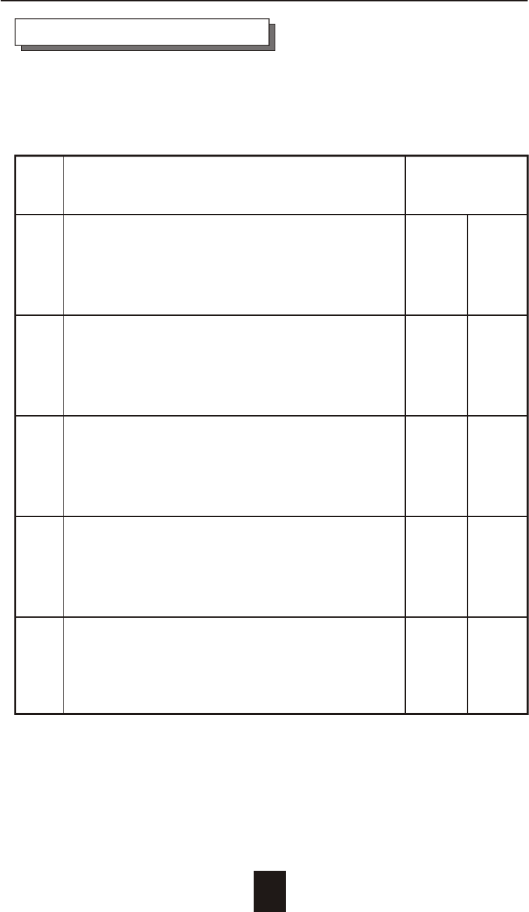
RAID Function Drives required
Level Description Min. Max.
"Disk Striping" , block striping is used,
0 which yields higher performance than with 2 16
the individual disk drives.
* There is no redundant function.
"Disk Mirroring" , Disk drives are mirrored ,
1 All data is 100% duplicated on each 2 16
equivalent disk drives.
* High Data Reliability
" Parallel Transfer Disks with Parity ",
3 Data is striped across physical drives. 3 16
Parity protection is used for data
redundancy.
Based on the needs of a Disk Array's capacity, data availability, and
overall performance, you can select a proper RAID level for your
Disk Array. The supported RAID levels are shown in below :
" Independent Access Array with Parity ",
5 Data is striped across physical drives. 3 16
Rotating Parity protection is used for data
redundancy.
0+1 " Disk Striping " + " Disk Mirroring " Function. 4 16
Supported RAID Levels
1-13
Introduction
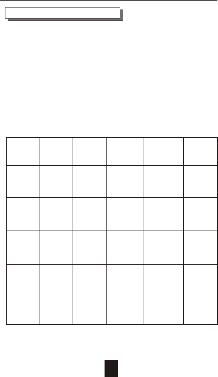
The Disk Array provides one LVD Ultra 160 SCSI channel for connect
to your host system. With proper cabling, it may support Narrow or
Wide; Standard, Fast or Ultra /Ultra 2 /Ultra 160 SCSI formats.
( single ended )
Overall cable length
For secure data transfer , please refer to the cable length limitations
as below :
* Cable length = External Host cables length + Internal Host cable
length
* Standard Disk Array External cable length = 90cm ( 3 ft )
* Standard Disk Array Internal cable length = 20cm
SCSI Clock Data Cable Remark
Type Rate R ate Required
LVD
Ultra 160 40 160 12m HPD 68---
(16 bit) MHZ MB/sec HPD 68 pin
LVD
Ultra 2 40 80 12m HPD 68---
(16 bit) MHZ MB/sec HPD 68 pin
Ultra
wide 20 40 2m HPD 68---
(16 bit) MHZ MB/sec HPD 68 pin
Ultra
SCSI 20 20 2m HPD 68---
(8 bit) MHZ MB/sec HPD 50 pin
SCSI 2 10 10 3m HPD 68---
(8 bit) MHZ MB/sec Cen. 50 pin
1-14
Maximum
Cable
Length
Multi-SCSI Format support