Medtronic MiniMed 2007C Implantable Insulin Pump User Manual Dmp9196021 011 c
Medtronic MiniMed, Inc. Implantable Insulin Pump Dmp9196021 011 c
UserManual.wiki
>
Medtronic MiniMed
>
2007C User Manual
>
physician part2
Contents
1.
Manual
2.
Patient Manual Cover
3.
Patient Manual
4.
Physician Manual Cover
5.
physician part1
6.
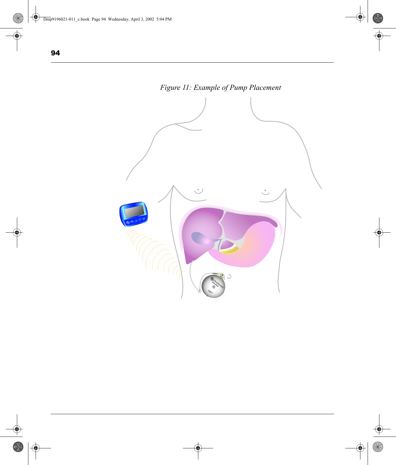
physician part2
7.
physician part3
8.
physician part4
physician part2
Navigation menu
Upload a User Manual
Namespaces
Wiki Guide
HTML
PDF
Info
Views
User Manual
Discussion / Help
Navigation