Medtronic MiniMed 3160 Personal Pump Communicator User Manual mp6025069 011 1
Medtronic MiniMed, Inc. Personal Pump Communicator mp6025069 011 1
Contents
- 1. Users Manual 1
- 2. Users Manual 2
- 3. Users Manual 3
Users Manual 2

Medtronic
MiniMed 2007D
Implantable
Insulin Pump
System
Physician’s
Manual
© 2003, Medtronic MiniMed. All rights reserved.
Medtronic MiniMed™ is a trademark of Medtronic MiniMed
Dual Wave™ is a trademark of Medtronic MiniMed
Square Wave™ is a trademark of Medtronic MiniMed
Steri-strip® is a registered mark from 3M
Aventis® is a registered mark from Aventis Pharmaceutical
Genapol® is a registered mark from Aventis Pharmaceutical
Luer Lok® is a registered mark from BD and Co.
This device is protected under one or more of the following U.S. Patents:
U.S., international, and foreign patent applications are pending.
4,731,051 5,217,442 5,527,307 6,427,088
4,776,842 5,257,971 5,559,828 6,537,268
5,167,633 5,460,618 5,797,733 6,562,001
5,176,644 5,466,218 5,915,929 6,564,105
5,197,322 5,514,103 6,283,943 6,571,128
6025069-011 7/04 REF MMT-3160
0976

i
Table of contents
CHAPTER 1 Description . . . . . . . . . . . . . . . . . . . . . . . . . . . . 1
Introduction . . . . . . . . . . . . . . . . . . . . . . . . . . . . . . . . . . . . . . . . . . . . . . . . . . . 1
Implantable Insulin Pump . . . . . . . . . . . . . . . . . . . . . . . . . . . . . . . . . . . . . . . . 3
Insulin medication . . . . . . . . . . . . . . . . . . . . . . . . . . . . . . . . . . . . . . . . . . . 5
Side Port Catheter . . . . . . . . . . . . . . . . . . . . . . . . . . . . . . . . . . . . . . . . . . . 6
Personal Pump Communicator (PPC) . . . . . . . . . . . . . . . . . . . . . . . . . . . . 7
CHAPTER 2 Indications and contraindications . . . . . . . . . . 9
Indications for use . . . . . . . . . . . . . . . . . . . . . . . . . . . . . . . . . . . . . . . . . . . . . . 9
Contraindications for use . . . . . . . . . . . . . . . . . . . . . . . . . . . . . . . . . . . . . . . . . 9
Possible adverse effects . . . . . . . . . . . . . . . . . . . . . . . . . . . . . . . . . . . . . . . . . 10
CHAPTER 3 Personal Pump Communicator (PPC) . . . . . . 11
Introduction . . . . . . . . . . . . . . . . . . . . . . . . . . . . . . . . . . . . . . . . . . . . . . . . . . 11
PPC icons . . . . . . . . . . . . . . . . . . . . . . . . . . . . . . . . . . . . . . . . . . . . . . . . . 11
PPC buttons . . . . . . . . . . . . . . . . . . . . . . . . . . . . . . . . . . . . . . . . . . . . . . . 12
Communicating with the Pump . . . . . . . . . . . . . . . . . . . . . . . . . . . . . . . . 12
Install/Replace the main battery . . . . . . . . . . . . . . . . . . . . . . . . . . . . . . . 13
Part 1: PPC/Pump system initialization . . . . . . . . . . . . . . . . . . . . . . . . . . . . . 15
Initialize the PPC . . . . . . . . . . . . . . . . . . . . . . . . . . . . . . . . . . . . . . . . . . . 15
Set the time and date . . . . . . . . . . . . . . . . . . . . . . . . . . . . . . . . . . . . . . . . 17
Set alarms . . . . . . . . . . . . . . . . . . . . . . . . . . . . . . . . . . . . . . . . . . . . . . . . . 18
Set maximum bolus, basal rate and time display format . . . . . . . . . . 19
Lock maximum bolus/basal, enter personal ID and
password, stop Pump . . . . . . . . . . . . . . . . . . . . . . . . . . . . . . . . . . 20

ii
Program a basal rate . . . . . . . . . . . . . . . . . . . . . . . . . . . . . . . . . . . . . . . . . 22
Part 2: Additional PPC programming features . . . . . . . . . . . . . . . . . . . . . . . 23
Main menu . . . . . . . . . . . . . . . . . . . . . . . . . . . . . . . . . . . . . . . . . . . . . . . . . . . 23
Program a bolus . . . . . . . . . . . . . . . . . . . . . . . . . . . . . . . . . . . . . . . . . . . . 23
Set a Normal bolus with the Variable Bolus feature turned off . . . . . . . . 24
Set a Normal bolus with the Variable Bolus feature turned on . . . . . . . . 25
Set a Square Wave Bolus . . . . . . . . . . . . . . . . . . . . . . . . . . . . . . . . . . . . . 26
Set a Dual Wave Bolus . . . . . . . . . . . . . . . . . . . . . . . . . . . . . . . . . . . . . . 27
Review bolus history . . . . . . . . . . . . . . . . . . . . . . . . . . . . . . . . . . . . . 28
Suspend mode . . . . . . . . . . . . . . . . . . . . . . . . . . . . . . . . . . . . . . . . . . 29
Programming a basal rate . . . . . . . . . . . . . . . . . . . . . . . . . . . . . . . . . . . . . . . 30
Programming basal delivery pattern . . . . . . . . . . . . . . . . . . . . . . . . . . . . 30
Setting basal rate profiles in each delivery pattern . . . . . . . . . . . . . . . . . 31
Program a temporary basal rate . . . . . . . . . . . . . . . . . . . . . . . . . . . . . . . . 32
Set a temporary basal rate . . . . . . . . . . . . . . . . . . . . . . . . . . . . . . . . . . . . 32
Stop a temporary basal rate . . . . . . . . . . . . . . . . . . . . . . . . . . . . . . . . . . . 33
Personal events . . . . . . . . . . . . . . . . . . . . . . . . . . . . . . . . . . . . . . . . . . . . . . . 34
History . . . . . . . . . . . . . . . . . . . . . . . . . . . . . . . . . . . . . . . . . . . . . . . . . . . 35
Setup Pump . . . . . . . . . . . . . . . . . . . . . . . . . . . . . . . . . . . . . . . . . . . . . . . . . . 37
Time and Date . . . . . . . . . . . . . . . . . . . . . . . . . . . . . . . . . . . . . . . . . . . . . 37
Auto off . . . . . . . . . . . . . . . . . . . . . . . . . . . . . . . . . . . . . . . . . . . . . . . . . . 37
Alarms . . . . . . . . . . . . . . . . . . . . . . . . . . . . . . . . . . . . . . . . . . . . . . . . . . . 38
Self test . . . . . . . . . . . . . . . . . . . . . . . . . . . . . . . . . . . . . . . . . . . . . . . . . . 38
Basal delivery pattern . . . . . . . . . . . . . . . . . . . . . . . . . . . . . . . . . . . . . . . 39
Initialize PPC to Pump . . . . . . . . . . . . . . . . . . . . . . . . . . . . . . . . . . . . . . . 39
Setup II . . . . . . . . . . . . . . . . . . . . . . . . . . . . . . . . . . . . . . . . . . . . . . . . . . . 39
Exit Setup menu . . . . . . . . . . . . . . . . . . . . . . . . . . . . . . . . . . . . . . . . . . . . 39
Setup II . . . . . . . . . . . . . . . . . . . . . . . . . . . . . . . . . . . . . . . . . . . . . . . . . . . . . . 40
Audio Bolus . . . . . . . . . . . . . . . . . . . . . . . . . . . . . . . . . . . . . . . . . . . . . . . . . . 40
Activating the Audio Bolus feature . . . . . . . . . . . . . . . . . . . . . . . . . . . . . 40

iii
Set an Audio Bolus from the main menu bolus screen . . . . . . . . . . . . . . 41
Variable Bolus . . . . . . . . . . . . . . . . . . . . . . . . . . . . . . . . . . . . . . . . . . . . . 41
Maximum Bolus . . . . . . . . . . . . . . . . . . . . . . . . . . . . . . . . . . . . . . . . . . . 42
Maximum Basal Rate . . . . . . . . . . . . . . . . . . . . . . . . . . . . . . . . . . . . . . . . 42
Time display format . . . . . . . . . . . . . . . . . . . . . . . . . . . . . . . . . . . . . . . . . 42
Personal Events . . . . . . . . . . . . . . . . . . . . . . . . . . . . . . . . . . . . . . . . . . . . 42
Pump Setup . . . . . . . . . . . . . . . . . . . . . . . . . . . . . . . . . . . . . . . . . . . . . . . 42
Exit Setup Menu . . . . . . . . . . . . . . . . . . . . . . . . . . . . . . . . . . . . . . . . . . . 42
Supervisor mode . . . . . . . . . . . . . . . . . . . . . . . . . . . . . . . . . . . . . . . . . . . . . . 43
Refill . . . . . . . . . . . . . . . . . . . . . . . . . . . . . . . . . . . . . . . . . . . . . . . . . . . . 43
Priming . . . . . . . . . . . . . . . . . . . . . . . . . . . . . . . . . . . . . . . . . . . . . . . . . . . 44
Diagnostic rate . . . . . . . . . . . . . . . . . . . . . . . . . . . . . . . . . . . . . . . . . . . . . 46
Initialize to factory defaults . . . . . . . . . . . . . . . . . . . . . . . . . . . . . . . . . . . 47
Stop Pump . . . . . . . . . . . . . . . . . . . . . . . . . . . . . . . . . . . . . . . . . . . . . . . . 49
Supervisor password . . . . . . . . . . . . . . . . . . . . . . . . . . . . . . . . . . . . . . . . 49
Exit supervisor . . . . . . . . . . . . . . . . . . . . . . . . . . . . . . . . . . . . . . . . . . . . . 49
Personal Pump Communicator messages . . . . . . . . . . . . . . . . . . . . . . . . 50
Technical history codes . . . . . . . . . . . . . . . . . . . . . . . . . . . . . . . . . . . . . . 51
Technical history PPC codes . . . . . . . . . . . . . . . . . . . . . . . . . . . . . . . 51
Clinical history Pump codes . . . . . . . . . . . . . . . . . . . . . . . . . . . . . . . 52
CHAPTER 4 Pump implantation . . . . . . . . . . . . . . . . . . . . . 53
Preprogramming and pre-testing the Pump . . . . . . . . . . . . . . . . . . . . . . . . . . 53
Registration card . . . . . . . . . . . . . . . . . . . . . . . . . . . . . . . . . . . . . . . . . . . 53
Supplies and solutions . . . . . . . . . . . . . . . . . . . . . . . . . . . . . . . . . . . . . . . 53
Supplies . . . . . . . . . . . . . . . . . . . . . . . . . . . . . . . . . . . . . . . . . . . . . . . 53
Solutions . . . . . . . . . . . . . . . . . . . . . . . . . . . . . . . . . . . . . . . . . . . . . . 54
Emptying and filling the Pump . . . . . . . . . . . . . . . . . . . . . . . . . . . . . . . . 54
Remove shipping fluid from the Pump . . . . . . . . . . . . . . . . . . . . . . . . . . 55
Rinse the Pump with insulin (IN1) . . . . . . . . . . . . . . . . . . . . . . . . . . . . . 56

iv
Fill the Pump with insulin . . . . . . . . . . . . . . . . . . . . . . . . . . . . . . . . . . . . 58
Measure stroke volume . . . . . . . . . . . . . . . . . . . . . . . . . . . . . . . . . . . . . . 59
Prepare the Side Port Catheter . . . . . . . . . . . . . . . . . . . . . . . . . . . . . . . . . 60
Performing the surgical procedure . . . . . . . . . . . . . . . . . . . . . . . . . . . . . . 64
Pre-operative evaluation . . . . . . . . . . . . . . . . . . . . . . . . . . . . . . . . . . 64
Formation of the pump pocket . . . . . . . . . . . . . . . . . . . . . . . . . . . . . . 64
Catheter placement . . . . . . . . . . . . . . . . . . . . . . . . . . . . . . . . . . . . . . 66
Post-operative management . . . . . . . . . . . . . . . . . . . . . . . . . . . . . . . . . . . 67
Post-operative hospitalization . . . . . . . . . . . . . . . . . . . . . . . . . . . . . . 67
Post-operative x-rays . . . . . . . . . . . . . . . . . . . . . . . . . . . . . . . . . . . . . . . . 67
CHAPTER 5 Pump refill procedure . . . . . . . . . . . . . . . . . . . 69
Introduction . . . . . . . . . . . . . . . . . . . . . . . . . . . . . . . . . . . . . . . . . . . . . . . . . . 69
Supplies and solutions . . . . . . . . . . . . . . . . . . . . . . . . . . . . . . . . . . . . . . . 70
Supplies: . . . . . . . . . . . . . . . . . . . . . . . . . . . . . . . . . . . . . . . . . . . . . . . 70
Solutions: . . . . . . . . . . . . . . . . . . . . . . . . . . . . . . . . . . . . . . . . . . . . . . 70
Prepare for pump refill . . . . . . . . . . . . . . . . . . . . . . . . . . . . . . . . . . . . . . . 71
Perform the refill procedure . . . . . . . . . . . . . . . . . . . . . . . . . . . . . . . . . . . . . . 72
Fill out the refill form . . . . . . . . . . . . . . . . . . . . . . . . . . . . . . . . . . . . . . . 72
Label syringes . . . . . . . . . . . . . . . . . . . . . . . . . . . . . . . . . . . . . . . . . . . . . 72
Prepare the refill syringe for emptying the Pump . . . . . . . . . . . . . . . . . . 72
Prepare the refill syringe for filling the Pump . . . . . . . . . . . . . . . . . . . . . 73
Empty the Pump . . . . . . . . . . . . . . . . . . . . . . . . . . . . . . . . . . . . . . . . . 73
Refill the Pump . . . . . . . . . . . . . . . . . . . . . . . . . . . . . . . . . . . . . . . . . 76
Calculate extracted and refill amounts . . . . . . . . . . . . . . . . . . . . . . . . 77
Calculate refill accuracy . . . . . . . . . . . . . . . . . . . . . . . . . . . . . . . . . . 77
CHAPTER 6 Explanting the Pump System . . . . . . . . . . . . . 79
Explant considerations . . . . . . . . . . . . . . . . . . . . . . . . . . . . . . . . . . . . . . . . . . 79
Returning devices/components to Medtronic MiniMed . . . . . . . . . . . . . . . . 79

v
CHAPTER 7 Warnings and precautions . . . . . . . . . . . . . . . 81
Warnings . . . . . . . . . . . . . . . . . . . . . . . . . . . . . . . . . . . . . . . . . . . . . . . . . . . . 81
Electrotherapy . . . . . . . . . . . . . . . . . . . . . . . . . . . . . . . . . . . . . . . . . . . . . 81
Diagnostic ultrasound . . . . . . . . . . . . . . . . . . . . . . . . . . . . . . . . . . . . . . . 82
Ultrasound therapy . . . . . . . . . . . . . . . . . . . . . . . . . . . . . . . . . . . . . . . . . . 82
Diagnostic radiation . . . . . . . . . . . . . . . . . . . . . . . . . . . . . . . . . . . . . . . . . 82
Elevated anti-insulin antibodies . . . . . . . . . . . . . . . . . . . . . . . . . . . . . . . . 82
Environmental conditions . . . . . . . . . . . . . . . . . . . . . . . . . . . . . . . . . . . . 83
Sterilization . . . . . . . . . . . . . . . . . . . . . . . . . . . . . . . . . . . . . . . . . . . . . . . 84
Precautions . . . . . . . . . . . . . . . . . . . . . . . . . . . . . . . . . . . . . . . . . . . . . . . . . . . 85
Emergencies and the use of conventional insulin supplies . . . . . . . . . . . 85
PPC reliability requirements . . . . . . . . . . . . . . . . . . . . . . . . . . . . . . . . . . 85
Maximum dosages . . . . . . . . . . . . . . . . . . . . . . . . . . . . . . . . . . . . . . . . . . 85
Electrical and magnetic fields . . . . . . . . . . . . . . . . . . . . . . . . . . . . . . . . . 86
CHAPTER 8 Adverse reactions . . . . . . . . . . . . . . . . . . . . . . 87
Adverse reactions . . . . . . . . . . . . . . . . . . . . . . . . . . . . . . . . . . . . . . . . . . . . . . 87
Prevention . . . . . . . . . . . . . . . . . . . . . . . . . . . . . . . . . . . . . . . . . . . . . . . . . . . 87
CHAPTER 9 System alarms and messages . . . . . . . . . . . . 89
Pump alarms . . . . . . . . . . . . . . . . . . . . . . . . . . . . . . . . . . . . . . . . . . . . . . . . . 90
Alarm feedback . . . . . . . . . . . . . . . . . . . . . . . . . . . . . . . . . . . . . . . . . . . . 90
Pump low battery . . . . . . . . . . . . . . . . . . . . . . . . . . . . . . . . . . . . . . . . . . . 90
Depleted pump battery . . . . . . . . . . . . . . . . . . . . . . . . . . . . . . . . . . . . . . . 90
System error . . . . . . . . . . . . . . . . . . . . . . . . . . . . . . . . . . . . . . . . . . . . . . . 91
Pump self test fail . . . . . . . . . . . . . . . . . . . . . . . . . . . . . . . . . . . . . . . . . . 91
PPC low battery . . . . . . . . . . . . . . . . . . . . . . . . . . . . . . . . . . . . . . . . . . . . 91
PPC alarms . . . . . . . . . . . . . . . . . . . . . . . . . . . . . . . . . . . . . . . . . . . . . . . . 92
Low reservoir . . . . . . . . . . . . . . . . . . . . . . . . . . . . . . . . . . . . . . . . . . . . . . 92
Empty reservoir . . . . . . . . . . . . . . . . . . . . . . . . . . . . . . . . . . . . . . . . . . . . 92
Telemetry communication error . . . . . . . . . . . . . . . . . . . . . . . . . . . . . . . . 92

vi
Initialize alarm . . . . . . . . . . . . . . . . . . . . . . . . . . . . . . . . . . . . . . . . . . . . . 93
PPC not initialized . . . . . . . . . . . . . . . . . . . . . . . . . . . . . . . . . . . . . . . . . . 93
Battery replacement . . . . . . . . . . . . . . . . . . . . . . . . . . . . . . . . . . . . . . . . . 94
Initialize to factory defaults . . . . . . . . . . . . . . . . . . . . . . . . . . . . . . . . . . . 94
Pump stopped . . . . . . . . . . . . . . . . . . . . . . . . . . . . . . . . . . . . . . . . . . . . . . 94
Pump suspended . . . . . . . . . . . . . . . . . . . . . . . . . . . . . . . . . . . . . . . . . . . 95
Auto off . . . . . . . . . . . . . . . . . . . . . . . . . . . . . . . . . . . . . . . . . . . . . . . . . . 95
Hourly maximum exceeded . . . . . . . . . . . . . . . . . . . . . . . . . . . . . . . . . . . 95
Pump alarm table . . . . . . . . . . . . . . . . . . . . . . . . . . . . . . . . . . . . . . . . . . . 96
CHAPTER 10 Troubleshooting Pump System
under-delivery . . . . . . . . . . . . . . . . . . . . . . . . . 97
Diagnostic procedures . . . . . . . . . . . . . . . . . . . . . . . . . . . . . . . . . . . . . . . . . . 97
Under-delivery caused by backflow . . . . . . . . . . . . . . . . . . . . . . . . . . . . . . . 97
Under-delivery caused by catheter occlusion . . . . . . . . . . . . . . . . . . . . . . . . 98
CHAPTER 11 Technical specifications . . . . . . . . . . . . . . . . . 99
Implantable Insulin Pump MMT-2007D . . . . . . . . . . . . . . . . . . . . . . . . . 99
Personal Pump Communicator (PPC) model MMT-3160 . . . . . . . . . . . 100
Side Port Catheter . . . . . . . . . . . . . . . . . . . . . . . . . . . . . . . . . . . . . . . . . 101
FCC compliance . . . . . . . . . . . . . . . . . . . . . . . . . . . . . . . . . . . . . . . . . . 101
APPENDIX A Label information symbol dictionary . . . . . . . . . . 103
Packaging . . . . . . . . . . . . . . . . . . . . . . . . . . . . . . . . . . . . . . . . . . . . . . . . . . . 104
Other information . . . . . . . . . . . . . . . . . . . . . . . . . . . . . . . . . . . . . . . . . . . . 104
APPENDIX B Implant worksheet . . . . . . . . . . . . . . . . . . . . . . . 105
Implant worksheet form . . . . . . . . . . . . . . . . . . . . . . . . . . . . . . . . . . . . . . . . 105
APPENDIX C Refill form . . . . . . . . . . . . . . . . . . . . . . . . . . . . . 107
Pump refill data . . . . . . . . . . . . . . . . . . . . . . . . . . . . . . . . . . . . . . . . . . . . . . 107
APPENDIX D Precautions and general procedures . . . . . . . . . 109
Special note and precautions . . . . . . . . . . . . . . . . . . . . . . . . . . . . . . . . . . . . 109

vii
General procedures . . . . . . . . . . . . . . . . . . . . . . . . . . . . . . . . . . . . . . . . 110
Locating the pump fill port and the side port . . . . . . . . . . . . . . . . . . . . . 111
Accessing the pump inlet . . . . . . . . . . . . . . . . . . . . . . . . . . . . . . . . . 112
Venting the Medtronic MiniMed refill syringe (optional) . . . . . . . . . . . 113
APPENDIX E Pump rinse procedure . . . . . . . . . . . . . . . . . . . . 115
Supplies and solutions . . . . . . . . . . . . . . . . . . . . . . . . . . . . . . . . . . . . . . . . . 115
Preparing for the procedure . . . . . . . . . . . . . . . . . . . . . . . . . . . . . . . . . . . . . 117
Prepare syringes for emptying the Pump . . . . . . . . . . . . . . . . . . . . . . . . 117
Prepare syringes for filling the Pump . . . . . . . . . . . . . . . . . . . . . . . . . . 117
Program minimal basal rate . . . . . . . . . . . . . . . . . . . . . . . . . . . . . . . . . . 118
Remove insulin from the Pump and fill with NaOH . . . . . . . . . . . . . . . . . . 118
Equilibrate and pull NaOH through system . . . . . . . . . . . . . . . . . . . . . . . . . 120
Remove NaOH and fill with rinse buffer . . . . . . . . . . . . . . . . . . . . . . . . 121
Equilibrate and pull rinse buffer through system . . . . . . . . . . . . . . . . . . 122
Remove rinse buffer and fill with insulin . . . . . . . . . . . . . . . . . . . . . . . 123
Equilibrate and pull insulin through system . . . . . . . . . . . . . . . . . . . . . 125
Remove guide needles and record fill amount . . . . . . . . . . . . . . . . . . . . 126
Program new basal rate . . . . . . . . . . . . . . . . . . . . . . . . . . . . . . . . . . . . . 126
APPENDIX F Side Port Catheter flush procedure . . . . . . . . . . 127
Supplies and solutions . . . . . . . . . . . . . . . . . . . . . . . . . . . . . . . . . . . . . . . . . 127
Preparing for the procedure . . . . . . . . . . . . . . . . . . . . . . . . . . . . . . . . . . . . . 128
Record patient’s blood glucose . . . . . . . . . . . . . . . . . . . . . . . . . . . . . . . 128
Prepare syringes for emptying the Pump . . . . . . . . . . . . . . . . . . . . . . . . 129
Prepare syringes for filling the Pump . . . . . . . . . . . . . . . . . . . . . . . . . . 129
Prepare syringe for flushing the Side Port Catheter . . . . . . . . . . . . . . . 129
Flushing the Side Port Catheter . . . . . . . . . . . . . . . . . . . . . . . . . . . . . . . . . . 130
Program minimal basal rate . . . . . . . . . . . . . . . . . . . . . . . . . . . . . . . . . . 130
Remove insulin and fill with rinse buffer . . . . . . . . . . . . . . . . . . . . . . . 130
Equilibrate and pull rinse buffer through system . . . . . . . . . . . . . . . . . . 131

viii
Flush side port catheter . . . . . . . . . . . . . . . . . . . . . . . . . . . . . . . . . . . . . 132
Remove rinse buffer and fill with insulin . . . . . . . . . . . . . . . . . . . . . . . 133
Equilibrate and pull insulin through system . . . . . . . . . . . . . . . . . . . . . 134
Remove guide needles and record refill amount . . . . . . . . . . . . . . . . . . 135
Program new basal rate . . . . . . . . . . . . . . . . . . . . . . . . . . . . . . . . . . . . . 135
Remove rinse buffer from catheter . . . . . . . . . . . . . . . . . . . . . . . . . . . . 136
APPENDIX G Stroke volume measurement . . . . . . . . . . . . . . . 137
Supplies and solutions . . . . . . . . . . . . . . . . . . . . . . . . . . . . . . . . . . . . . . . . . 137
Preparing for the procedure . . . . . . . . . . . . . . . . . . . . . . . . . . . . . . . . . . . . . 138
Record patient’s blood glucose . . . . . . . . . . . . . . . . . . . . . . . . . . . . . . . 138
Measuring stroke volume . . . . . . . . . . . . . . . . . . . . . . . . . . . . . . . . . . . . 138
Record patient’s blood glucose . . . . . . . . . . . . . . . . . . . . . . . . . . . . . . . 140

ix
List of figures
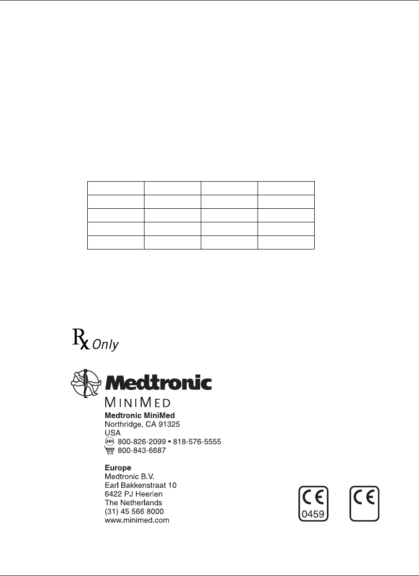
Figure 1: Implantable Insulin Pump and
Personal Pump Communicator (PPC) . . . . . . . . . . . . . . . 1
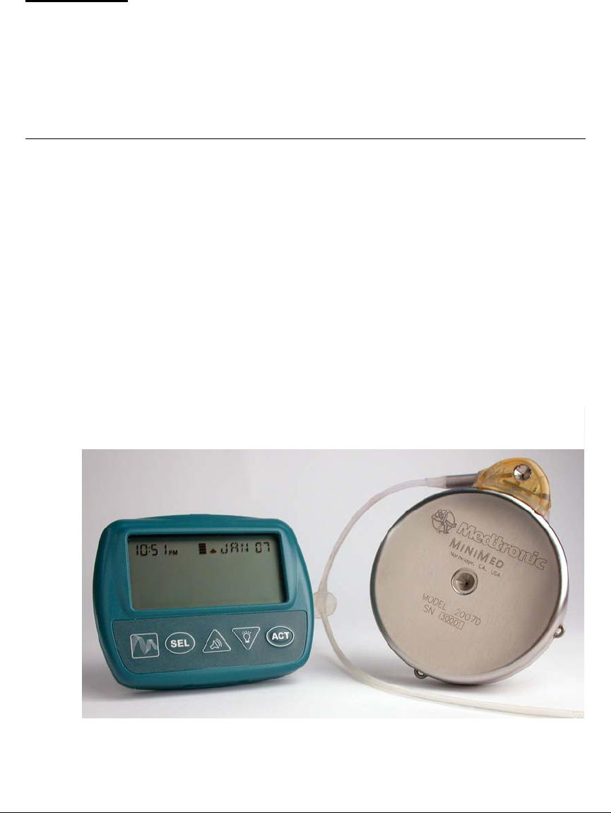
Figure 2: The Implantable Insulin Pump . . . . . . . . . . . . . . . . . . . . 3
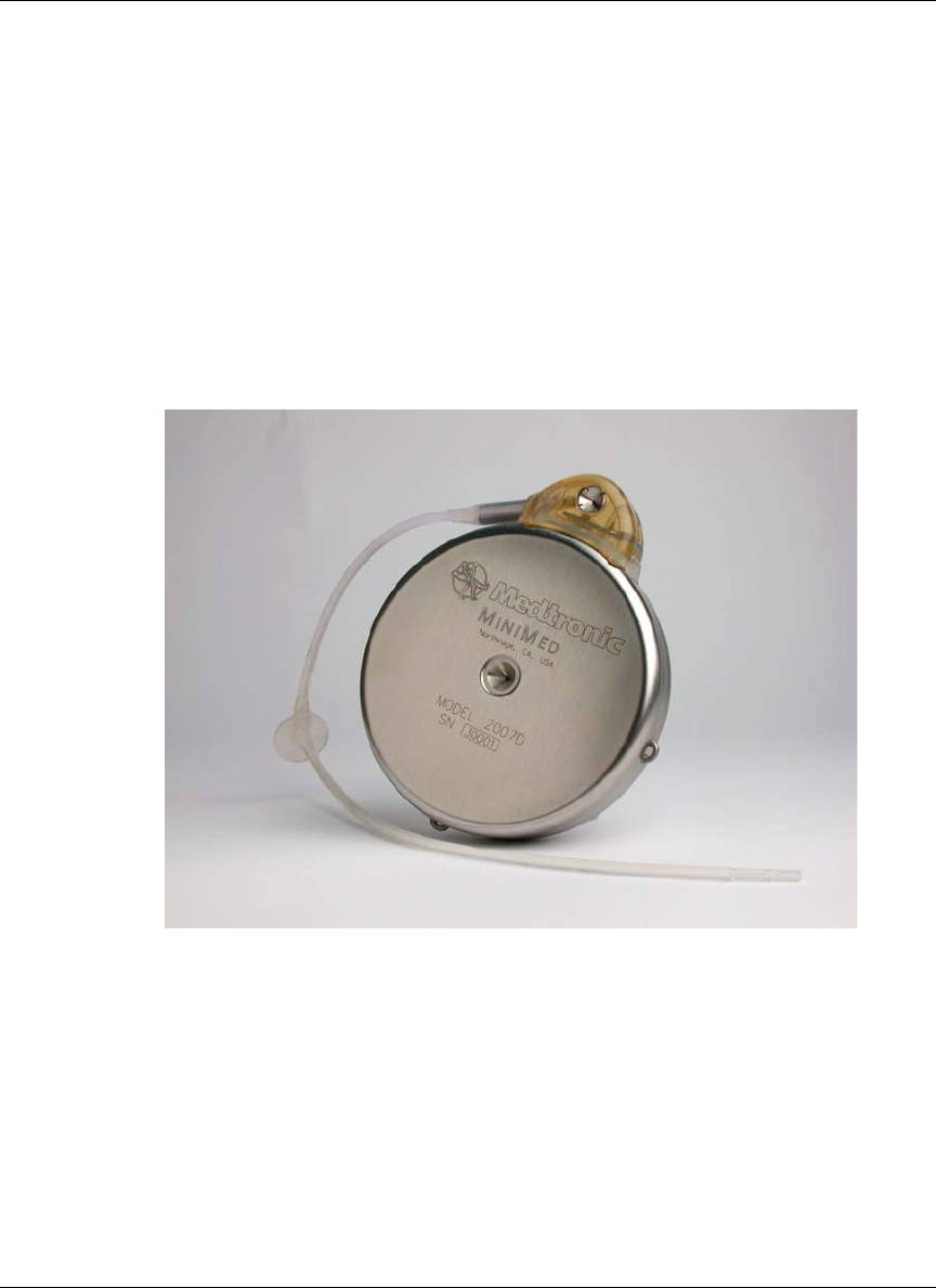
Figure 3: Interior of the Implantable Insulin Pump . . . . . . . . . . . . 4
Figure 4: The Intraperitoneal Catheter and Side Port . . . . . . . . . . . 6
Figure 5: Personal Pump Communicator (PPC) . . . . . . . . . . . . . . . 7
Figure 6: Filling the hub of the refill needle . . . . . . . . . . . . . . . . 55
Figure 7: Venting the syringe head space . . . . . . . . . . . . . . . . . . 57
Figure 8: Testing Pump stroke volume with a pipette . . . . . . . . . 60
Figure 9: Tubing and retainer removal . . . . . . . . . . . . . . . . . . . . . 61
Figure 10: Proper attachment of the Side Port Catheter to Pump . 62
Figure 11: Example of Pump placement . . . . . . . . . . . . . . . . . . . . 65
Figure 12: Filling the hub of the refill needle . . . . . . . . . . . . . . . . 72
Figure 13: Operation of the Pump inlet valve . . . . . . . . . . . . . . . . 74
Figure 14: Venting the Medtronic MiniMed refill syringe . . . . . . 76
Figure 15: Template and placement . . . . . . . . . . . . . . . . . . . . . . . 111
Figure 16: Inlet valve . . . . . . . . . . . . . . . . . . . . . . . . . . . . . . . . . . 112
Figure 17: Venting the refill syringe . . . . . . . . . . . . . . . . . . . . . . 113
Figure 18: Stroke volume measurement setup . . . . . . . . . . . . . . . 138
Figure 19: Stroke volume measurement . . . . . . . . . . . . . . . . . . . . 139

x
1
CHAPTER 1 Description
Introduction
The Medtronic MiniMed 2007D Implantable Insulin Pump System, shown in
Figure 1, brings together sophisticated new technologies to provide continuous
intraperitoneal insulin therapy for patients with Insulin Dependent Diabetes
Mellitus (IDDM). The development of the Medtronic MiniMed 2007D
Implantable Insulin Pump System is the result of years of cooperative research
and development between Medtronic MiniMed and:
• The Johns Hopkins University, Applied Physics Laboratory
• U.S. National Aeronautics and Space Administration, Goddard Space
Flight Center. U.S. National Institutes of Health
Figure 1: Implantable Insulin Pump and
Personal Pump Communicator (PPC)

Description
2
This manual is intended for use by the physician, surgeon, nurse specialist and all
other members of the healthcare team who care for patients with the Medtronic
MiniMed 2007D Implantable Insulin Pump System.
The Medtronic MiniMed 2007D Implantable Insulin Pump System can be used
with special U-400 insulin formulations specifically labeled for use with the
Medtronic MiniMed Implantable Insulin Pump System.
The system consists of three major components:
• Implantable Insulin Pump
• Side Port Catheter
• Personal Pump Communicator (PPC)
Each of these components, as well as system safety features, are discussed in
detail in the following sections.
Description 3
Implantable Insulin Pump
The Implantable Insulin Pump (Pump) is a round disc, 8.1 cm (3.2 inches) in
diameter, 2.0 cm (0.8 inches) thick. The Pump weighs 131 grams (4.6 ounces)
when empty. The outside case of the Pump is made of titanium. Titanium is a
biocompatible metal used in many types of implantable medical devices. A
tangential Side Port Catheter is attached to the Pump prior to implant, using a
locking connector (see Figure 2).
Figure 2: The Implantable Insulin Pump
The Implantable Insulin Pump is an advanced insulin infusion device with
sophisticated microelectronics. It delivers a special insulin medication, using a
pulsatile solenoid pumping mechanism that is hermetically sealed inside the
biocompatible titanium case. Insulin delivery rates and profiles are programmed
using an external device, the Personal Pump Communicator (PPC). Specific
information on the Implantable Insulin Pump features is outlined in the following
sections.
Description
4
The Pump has six major components. These components are outlined below:
• medication reservoir
• pumping mechanism
• microelectronics
• antenna
• battery
• tone transducer
Other components of the Pump include the inlet valve, fill port, septum,
cyclopentane gas and 20µm filter. Figure 3 shows the interior components of the
Pump.
Figure 3: Interior of the Implantable Insulin Pump
The Medication Reservoir stores approximately 15 ml or 6,000 units of a
special U-400 insulin. Depending on an individual’s insulin requirements, the
medication reservoir is refilled once in approximately every two to three months.
The medication reservoir is maintained at a negative pressure (vacuum) at all
times to allow for safe and reliable filling. This vacuum prevents any risk of
insulin leakage in the event of a breach in the Pump case or reservoir. The
reservoir is refilled with a special needle (Medtronic MiniMed Refill Needle
MMT-4102). The fill port has a 20 micron filter to prevent particulate material
from entering the Pump and a redundant septum and valve configuration to
prevent entry of body fluids.

Description 5
The Pumping Mechanism is a solenoid-operated, hermetically-welded pulsatile
system. The pumping mechanism is designed to seal automatically to prevent
leakage both into and out of the reservoir under physiologic temperatures and
pressures. The mechanism is designed to provide an insulin delivery accuracy of
within 10% from its labeled stroke volume. Individual Pumps are calibrated to
one of seventeen different stroke volumes, ranging from 0.42 µL to 0.58 µL per
stroke, in increments of 0.01 µL.
The Microelectronics act as the brain of the Pump. The microelectronics contain
two microprocessors which monitor and control all pump-stroke activity. All
commands delivered from the PPC via RF telemetry to the Pump are then
acknowledged back to the PPC. The Pump has a large memory which stores
Pump specifications and programming history.
The Antenna receives radiowaves from the PPC and delivers PPC programming
commands to the Pump microelectronics.
The Battery is a custom-made lithium carbon mono-fluoride power cell, which
supplies energy to the pumping mechanism and microelectronics. It is similar to
batteries used in pacemakers and is designed to provide 6 to 10 years of service,
depending on the infusion rate (refer to pump specifications).
The Tone Transducer emits beeps to indicate certain alarm conditions. These
beeps are designed to be audible through the skin and can be set with the PPC to
one of two volumes. The Pump can also be programmed to emit beeps that signal
a programmed change in the medication delivery rate.
Radio-Opaque Identification is featured in the Implantable Insulin Pump. In
the event of an emergency, the name of the manufacturer and the Pump model
number can be identified with an x-ray.
Insulin medication
Only specially formulated U-400 insulins that are specifically labeled for use
with the Medtronic MiniMed Implantable Insulin Pump System can be used in
the model 2007D Pump.
These special U-400 insulins are supplied in 10mL vials.
Description
6
Side Port Catheter
The Side Port Catheter (Catheter) transports insulin from the Pump into an
individual’s peritoneum where it is absorbed. The Catheter is made of
polyethylene-lined silicone rubber, which is biocompatible with subcutaneous
and intraperitoneal tissues and supports the stability of the special insulin. The
Catheter is designed with two perpendicular sections: a proximal subcutaneous
section which attaches tangentially to the Pump with a locking connector, and a
distal section which is placed in the peritoneum (see Figure 4). To enable post-
implant localization, a radioopaque stripe runs the length of the Catheter.
The Catheter Side Port is intended to provide access to the Catheter and Pump
outlet, in order to perform the non-surgical interventions and diagnostic
procedures described in Appendices E, F and G. The side port allows for the
introduction of a needle and small syringe to clear Catheter obstructions using
pressures up to 100 psi. It also allows for the introduction of a needle to verify
Pump stroke volume.
Figure 4: The Intraperitoneal Catheter and Side Port
Description 7
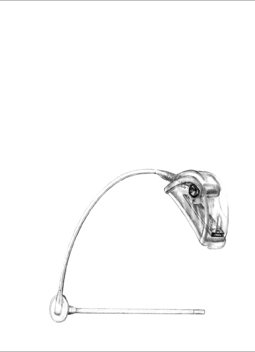
Personal Pump Communicator (PPC)
The Personal Pump Communicator (PPC) is the hand-held component of the
Medtronic MiniMed 2007D Implantable Pump System (see Figure 5).
The PPC allows the physician and patient to communicate with the Pump by
transmitting radio frequency messages when the PPC is held within 3” of the
Pump. Additionally, the PPC stores important programming information in its
memory.
Figure 5: Personal Pump Communicator (PPC)
The PPC has been designed so the physician and patient can:
• Program basal infusion rates (up to 48 basal rates per day, 3 different
patterns)
• Deliver or suspend an immediate, Square Wave, or Dual Wave Bolus of
insulin
• Deliver or cancel a temporary basal rate
• Review the insulin delivery history
• Enter personal events (meal, snack, exercise)
Independent of the programming function, the PPC is able to receive and record
certain programming data from the Pump. The recorded information is accessible
and can be displayed on the screen.

Description
8

9
CHAPTER 2 Indications and
contraindications
Indications for use
The Medtronic MiniMed 2007D Implantable Insulin Pump System is indicated
for intraperitoneal administration of exogenous insulin in patients with diabetes
mellitus.
The model 2007D Pump can only be used with special U-400 Insulin
formulations specifically labeled for use with the Medtronic MiniMed
Implantable Insulin Pump Infusion System.
Contraindications for use
The Medtronic MiniMed 2007D Implantable Insulin Pump System is
contraindicated in patients who:
• are unwilling or unable to monitor their blood glucose level at least four
times per day.
• are unwilling or unable to make programming modifications to the Pump
based on glucose level readings.
• are unable or unwilling to administer insulin by other means, if necessary.
• are unable or unwilling to comply with the guidance and advice of their
treating physician and other healthcare providers.
• reside at or travel (other than by pressurized commercial aircraft) at
elevations above 8,000 feet.
• have other medical or mental conditions which may place the patient at risk.
• are unwilling or unable to return for routine insulin refills according to their
dosage requirements (approximately once every 90 days).
• present or have a history of sensitivity to titanium alloy, polysulfone or
silicone materials used in the implanted components of the system.

Indications and contraindications
10
Possible adverse effects
The model 2007D is essentially identical to the model 2007C Pump except for
the change in gas needed to maintain negative pressure in the reservoir.
Evaluation of components used in the Medtronic MiniMed 2007C system has
spanned a period of approximately 4 years and involved approximately 380
patients from both the U.S. and Europe. Although clinically relevant over-
delivery of insulin did not occur during the 4 year evaluation period, there is a
potential for such an occurrence.
The following are specific adverse effects which should be understood by the
physician and explained to the patient. These do not include all adverse effects
which can occur with surgery in general or with the use of this device, but are
important considerations, particularly in the treatment of diabetic patients. The
general surgical risks, as well as operative site cosmetic risks, should be
explained to the patient prior to surgery.
• Abdominal Pain • Foreign Body Reaction
• Inflammation at Refill Site • Skin Erosion
• Infection • Pocket Lymph Edema
• Necrosis • Hyperglycemia
• Hypoglycemia • Ketoacidosis

11
CHAPTER 3 Personal Pump
Communicator (PPC)
Introduction
The Personal Pump Communicator (PPC) has a comprehensive set of program-
ming features to control the Implantable Insulin Pump. The PPC cannot be used
by the patient until it has been initialized by the healthcare professional. This
chapter of the manual is divided in two parts:
The first part (Part 1) will describe the PPC/PUMP system initialization process
that will be performed the day prior to implant.
The second part (Part 2) will describe how to use the additional features that the
healthcare professional or patients can activate.
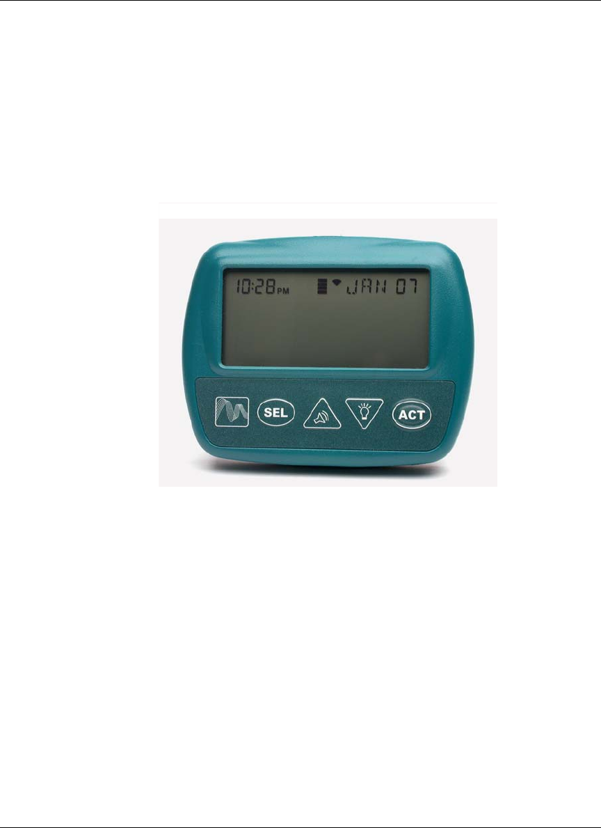
PPC icons
After initialization, the PPC Main Screen displays the time (12hr. or 24hr. for-
mat), month, day and a variety of icons. The type and purpose of these icons are
as follows:
Bell Icon:
Displayed when the PPC receives a telemetry message from the Pump indicating
that the Pump has detected an alarm condition, when a PPC error is detected and
when the Pump is Suspended or Stopped.
Reservoir Level Indicator Icon:
The reservoir icon is composed of 4 segments that indicate how full the Pump
reservoir is, based on the history of Pump delivery.
Insulin Delivery Icon:
The PPC simulates spinning the delivery icon when insulin delivery is in progress
by displaying alternating patterns, the pattern changes every 4 seconds. When the
Pump is delivering a bolus, the pattern will show three delivery segments. When
the Pump is delivering a basal rate, the pattern will show one delivery segment.
When the Pump is not delivering, all four segments will be displayed.

Personal Pump Communicator (PPC)
12
Certain features of the PPC such as programming and dosing limits can be set
only by the healthcare professional in a password-protected mode called the
Supervisor Mode. Information pertaining to initializing the PPC and entering the
PPC Supervisor Mode is not included in the Patient User Manual.
PPC buttons
Communicating with the Pump
Place the PPC near the Pump when the screen displays,
“PPC COMMUNICATING.” The word "COMMUNICATING" will blink as
indication of successful communication. If a communication link between the
PPC and Pump is not established, a “TELEMETRY COMM ERROR 3” message
will appear. The PPC will beep six times once every minute until the screen is
acknowledged by pressing SEL and ACT. The screen will then display “PPC
COMMUNICATING” again.
After a communication is established between the PPC and Pump and program
information is successfully transferred to the Pump, the PPC will beep once and
return to the Time/Date screen.
• Always press the PPC buttons slowly and firmly. Wait until the screen
changes before pressing the button again.
• A flashing value on the screen means that the value is activated, and can be
changed by pressing the arrow buttons.
SEL
(Select) The SEL button steps through each of the displays and menus.
ACT
(Activate) The ACT button activates programming changes in the Pump, new
information to be entered into the PPC memory, and alarms to be turned off.
As a safety check, ACT must be pressed to complete any programming
changes. A single beep is heard after activating a change.
or
(Up or Down
Arrows)
The or arrows allow changes in the screen settings. Pressing once
will find the next highest setting, and pressing once will find the next
lowest setting. Holding down either button will rapidly scroll through the list
of preset values. Desired values can then be programmed by pressing ACT.
Sound Icon
(Up Arrow) When the Audio Bolus feature is turned on, pressing allows programming
an Audio Bolus.
Light Icon
(Down Arrow) From the main operating screen, pressing once will turn on the backlight.
The backlight allows the Pump to be programmed in the dark. The backlight
will turn off automatically after four seconds after the last button press.

Personal Pump Communicator (PPC) 13
• The PPC cannot be turned off. Once the battery has been installed, the PPC
is on and remains on until the battery is removed.
• Certain types of Radio Frequency (RF) generating equipment could affect
PPC communication with the Pump. If you are experiencing
communication difficulties, change locations.
• The time and date settings must be correct to ensure appropriate calculation
of insulin delivery and display of daily totals and activity history.
Install/Replace the main battery
The battery used to power the PPC is a 1.5V AA alkaline. The life of the battery
is approximately 4 weeks during normal usage conditions.
• Locate the battery door on the back of the PPC.
• Slide the locking bar to the left.
• Push the middle part of the PPC box (under the battery door) and lift by
gently pulling up the battery door to unlatch.
• Remove the old battery, noting the polarity. The screen will be blank.
• Position the new battery so the + and - markings on the battery match the
polarity diagram in the battery compartment.
• Close the battery door.
• Slide the locking bar to the right.
• The PPC screen will reappear within 30
seconds:
1. The PPC will beep 6 times, and after a few
seconds, the screen will display
“CHECK PUMP STATUS”.
PPC
PUMP
8 102 100
__ __ __
08:26
CHECK
PUMP STATUS
JAN O2

Personal Pump Communicator (PPC)
14
2. Press SEL then ACT, and place the PPC near the
Pump.
3. Wait a few seconds for the communication to
complete.
NOTE: When the PPC displays “PPC
LOW BATTERY”, the message can be cleared, and
programming continued. There should be sufficient
energy in the battery to communicate with the Pump a few
more times, but the battery should be changed as soon as
possible.
NOTE: If while programming the PPC, the screen goes blank, the
PPC beeps six times and then the “CHECK PUMP
STATUS” message appears, the battery needs to be
replaced.
PPC
COMMUNICATING

Personal Pump Communicator (PPC) 15
Part 1: PPC/Pump system initialization
The Implantable Insulin Pump arrives from Medtronic MiniMed with preset fac-
tory default values. During the initialization process these preset values are
downloaded into the PPC memory. The preset values can then be changed by the
healthcare professional, allowing the system to be personalized for each patient.
The factory default values are as follows:
Initialize the PPC
When the healthcare professional receives a new PPC it must be “married” to the
Pump. Following are the basic steps used to initialize a Pump System the day
prior to implant:
1. The PPC is delivered without a battery in place.
After installing a new battery, the PPC will beep
six times and the screen will identify the PPC
software used (see Chapter 3, Install/Replace the
Main Battery).
2. The screen now changes to
“PPC NOT INITIALIZED”, and the PPC will
beep six times once every minute until the
initialization process is started. Press SEL and
then ACT, then quickly place the PPC over the
Pump.
Bolus delivery type: Normal Locked set maximums: Off
Maximum bolus: 25.0 U Password: YIQ8
Audio bolus: Off Personal Events status: OFF
Audio feedback: Disabled Personal ID: 000 (32 characters)
Auto Off duration: Off PPC alarm type: High
Basal delivery pattern: A Refill amount: 25 g
Maximum basal rate: 35.0 U/H Time format: 12 hours
Insulin concentration: 400 U/ml Variable Bolus status: Off
PUMP
PPC 8 102 100
— — —
PPC
NOT INITIALIZED

Personal Pump Communicator (PPC)
16
3. When a communication link has been established,
the screen will read, “PPC COMMUNICATING”,
and then will change to the next screen.
4. “NO” is blinking. Check to make sure the serial
number displayed on the screen matches the
Pump serial number. Press either or once to
change “NO” to “YES” and then press ACT.
Place the PPC over the Pump.
5. The screen again reads “PPC
COMMUNICATING”, and the PPC will beep 3
times at the end of the programming sequence.
During this process, the PPC receives all of the
factory preset values contained in the Pump
memory.
6. The screen will read “PUMP SUSPENDED”. The
Pump and PPC are now “married”.
7. Press SEL, then ACT and place the PPC near the
Pump.
8. The screen now reads “PUMP INITIALIZED”.
9. Press SEL and then ACT again, and the PPC will
display the Time/Date screen.
NOTE: When the alarm type is set to
“VIBRATE” the beeps from the
PPC during normal programming
will be low volume.
PPC
COMMUNICATING
INITIALIZING "NO"
PPC to PUMP
• • • • • • • • • • • • • • • •
• • • • • • • • • • • 47568
COMMUNICATING
PPC
PUMP SUSPENDED
PPC
COMMUNICATING
PUMP INITIALIZED
11:16 JAN O2

Personal Pump Communicator (PPC) 17
Set the time and date
The time and date settings must be correct to ensure accurate calculation of insu-
lin delivery, daily totals, and the proper display of insulin activity history.
1. Press SEL until the “SETUP PUMP” screen is
displayed, then press ACT two times. The first
two digits of the time (hours) will be flashing.
Use the and buttons to select the correct
hour, then press ACT. The last two digits of the
time (minutes) will be flashing. Use the and
buttons to select the correct minute, then press
ACT. Repeat the programming process to enter
information for the year, month and day.
2. After completing the programming process, then
place the PPC near the Pump. The PPC will
display “PPC COMMUNICATING” while
transferring the time and date information to the
Pump. The PPC will then move to the next
screen, “AUTO-OFF.” Skip the “AUTO-OFF”
screen by pressing SEL once to reach the next
screen, “ALARMS”.
08:32
SET
TIME-DATE 2004
Jan 02
PPC
COMMUNICATING

Personal Pump Communicator (PPC)
18
Set alarms
Alarms alert the user in the event the PPC or Pump recognizes an insulin delivery
problem. The Alarm Feedback screen must always be in the “ON” position.
1. Press ACT to enter the “ALARMS” menu.
2. The PPC has three alarm options, two audible
tones (Low/High) and a vibrate mode. Press the
and buttons to select the desired alarm, then
press ACT.
3. The screen will now display “SET ALARM
FEEDBACK”. This setting should always be
“ON”. Press ACT.
4. Place the PPC near the Pump. When the
communication is completed, the PPC screen
will change to “SELF TEST” and then to the
Time/Date screen.
NOTE: When the alarm type is set to “vibrate” the beeps from the
PPC during normal programming will be low volume.
ALARMS
SET
PPC
ALARM TYPE
LOW/HIGH/VIBRATE
SET
ALARM
FEEDBACK
ON/OFF
PPC
COMMUNICATING
SELF TEST

Personal Pump Communicator (PPC) 19
Set maximum bolus, basal rate and time display format
This programming is performed in the “SETUP II” menus. These screens allow
healthcare professionals to limit the maximum amount of insulin a patient can
deliver, either when taking a bolus or setting a new basal rate. Access to the
“SETUP II” menus is through the “SETUP PUMP” screen.
1. Press SEL until the “SETUP PUMP” screen is
displayed. Press ACT and press SEL to reach
the “SETUP II” screen. Press ACT and then
SEL to reach the “MAX BOLUS” screen.
2. Press ACT and the maximum bolus amount
(units) will start flashing. Press the and
buttons to change the maximum allowable bolus
(0.2 to 25.0 units) and then press ACT again.
3. Place the PPC near the Pump and complete the
communication process. The PPC screen will
automatically change to the “MAX BASAL”
screen.
4. Press ACT and the screen will change to “SET
MAX BASAL RATE”. The maximum basal
amount will start flashing. Press the and
buttons to change the maximum allowable basal
rate (0.2 to 35.0 units/hour) and then press ACT
again.
5. Place the PPC near the Pump and complete the
communication process. The PPC screen will
automatically change to “TIME FORMAT.”
6. Press ACT and the screen will change to “SET
TIME FORMAT.” Press the and buttons to
select either a 12 hour (AM/PM) or 24 hour
(military time) format, and then press ACT.
MAX BOLUS
_ _ U
MAX BOLUS
SET
_ _ U
PPC
COMMUNICATING
MAX BASAL RATE
SET
0.2U/H
PPC
COMMUNICATING
SET
TIME FORMAT
12/24 HOUR
Personal Pump Communicator (PPC)
20
7. Place the PPC near the Pump and complete the
communication process. The PPC screen will
return to the “PERSONAL EVENTS” screen.
Allow the PPC to time out and return to the
Time/Date screen.
NOTE: Adding screens to the main menu, such as “PERSONAL
EVENTS” increases the number of SEL button presses
required to reach “SETUP PUMP.”
Lock maximum bolus/basal, enter personal ID and password,
stop Pump
To access the Supervisor Mode press SEL until the “SETUP PUMP” screen is
displayed. Then press and hold down the and buttons simultaneously until
the “ENTER SUPERVISOR PASSWORD” screen appears.
Patients should not be given the Supervisor
Mode password, to avoid the accidental pro-
gramming of a large priming bolus (99.8 U) or
diagnostic insulin rate.
1. The first zero will be flashing. Press the and
buttons to select the first digit, then press ACT.
The screen advances to the second zero. Press
the and buttons to select the second digit,
then press ACT. Repeat for the last two digits.
The factory pre-set password is YIQ8.
2. Entry into the Supervisor Mode is indicated by
the screen “PUMP REFILL.”
3. Press SEL until the “SET MAXIMUMS" screen
is displayed, and then ACT to reach “SET
MAXIMUMS”.
Press the and buttons to select “ON” if the
patient is not given access to this feature, or
“OFF” if the patient is permitted access. Press
ACT again.
PPC
COMMUNICATING
!
WARNING
ENTER
SUPERVISOR
PASSWORD
0000
PUMP
REFILL
SET
MAXIMUMS OFF/ON

Personal Pump Communicator (PPC) 21
4. Place the PPC near the Pump and complete the
communication process. The PPC screen will
automatically advance to the “PERSONAL ID”
screen. Press ACT.
5. The first of the 32 possible ID locations is
flashing. Enter the patient ID (alpha-numeric) by
pressing the and buttons and then ACT
after each entry. Continue to press ACT,
activating each “0” until the screen changes.
6. Place the PPC near the Pump and complete the
communication process.
7. Press SEL until the “SET SUPERVISOR
PASSWORD” screen is displayed. Then press
ACT.
8. The screen now reads, “SET SUPERVISOR
PASSWORD”. Press ACT. Use the and
buttons to enter a new supervisor password
(alphanumeric), pressing ACT after each entry.
9. Record the password in the patient’s chart and
implant form.
PPC
COMMUNICATING
SET PERSONAL ID
• • • • • • • • • • • • • • • •
• • • • • • • • • 20KOLO5
PPC
COMMUNICATING
SET
SUPERVISOR
PASSWORD
YIQ8
SET
SUPERVISOR
PASSWORD
0000

Personal Pump Communicator (PPC)
22
Program a basal rate
1. From the Time/Date screen, press SEL until the
“BASAL RATE” screen is displayed. Preset
delivery pattern “A”, a basal rate of 0.2 U/H, and
the word “NOW” is flashing. Press ACT.
2. A “1” now appears to the right of the “A”
indicating that this programming will effect the
1st basal change within the “A” pattern, (there
are 3 patterns available [A, B, C] and 48 basal
changes possible within each pattern). The
flashing 0.2 U/H indicates the value can be
changed. Use the and buttons to change the
value and then press ACT.
NOTE: 00:00 indicates a start time of MIDNIGHT in 24hr.
display mode. In 12hr. display mode, the screen indicates
the start time as 12:00am.
3. The screen now displays “SET TIME”, and a
time of 00:30 or 12:30 am (24 or 12 hour
respectively) and a “2.”
If one basal is all that will be used, press ACT
two times. If more than one basal rate is to be
programmed, enter a start time and amount of the new basal rate for that time
period, then press ACT and enter the new basal rate. The user can enter a
new basal rate at 30 minute intervals, up to 48 basal rates.
4. Place the PPC near the Pump and complete the
communication process.
5. The PPC will briefly display the calculated total
basal dose for 24 hours, based on the values and
times entered in the Basal Rate programming
screen. In this example, the total basal dose is
4.8 U/day.
08:26 OCT 12
BASAL RATE: A NOW 1
00:00 0.2U/H
BASAL RATE A
00:30 _ _ U/H
s 2
PPC
COMMUNICATING
24 HOUR TOTAL
4.8U

Personal Pump Communicator (PPC) 23
Part 2: Additional PPC programming features
Main menu
This second part will describe how to program the additional features that the
patient or the healthcare professional can activate.
Program a bolus
A properly initialized PPC is now ready to program a bolus.
The PPC/Pump allows you to set and deliver a bolus of insulin whenever needed.
The PPC has several special features which allow you to customize the program-
ming and delivery of boluses.
• Normal Bolus and Audio Bolus
• Square Wave Bolus
• Dual Wave Bolus
NOTE: To use the Variable Bolus programming options, (e.g.
square, dual), this option needs to be programmed “ON”
in the SETUP II menu. If it is not “ON” only the default
bolus, “Normal bolus”, will be available.

Personal Pump Communicator (PPC)
24
Set a Normal bolus with the Variable Bolus feature turned
off
1. From the Time/Date screen, press SEL.
The “BOLUS” screen is displayed, with the time
and date flashing.
2. Press ACT and the “SET BOLUS” screen
appears. The dashes under “IMM” are flashing.
Press the and buttons to enter an immediate
bolus amount.
3. Press ACT and the “CONFIRM” screen is
displayed, with the screen flashing. Confirm the
bolus amount by pressing ACT again.
4. Place the PPC near the Pump and complete the
communication process.
5. When the bolus programming is complete, the
PPC will beep once and then briefly display the
amount of insulin currently delivered.
The Pump will beep at each of the first five
strokes (if audio feedback is ON). The PPC
beeps and at the end of the bolus. Three
segments of the insulin delivery icon will be
displayed and spinning slowly during the bolus
delivery. By pressing SEL you can read the
amount of insulin delivered.
08:13
BOLUS
PROG
IMM
10U 10U
Jas2
--
EXT
SET BOLUS
IMM
_ _ U
CONFIRM
2.6U
IMM
PPC
COMMUNICATING
08:13
BOLUS 0.0U
Jan 02

Personal Pump Communicator (PPC) 25
Set a Normal bolus with the Variable Bolus feature turned
on
1. From the Time/Date screen press SEL until the
“BOLUS” screen is displayed. The last bolus
value programmed and the Time and Date will
be flashing.
2. Press ACT and the “SET BOLUS TYPE” screen
appears. If “NORMAL” is not flashing, use the
and buttons to select “NORMAL.” Press
ACT.
3. The “SET BOLUS” screen appears, with dashes
under “IMM” flashing. Use the and buttons
to enter an immediate bolus amount.
4. Press ACT and the “CONFIRM” screen is
displayed, with the screen flashing. Confirm the
bolus amount by pressing ACT again.
5. Place the PPC near the Pump and complete the
communication process.
6. When the bolus programming is complete, the
PPC will beep once and then briefly display the
amount of insulin currently delivered.
The Pump will beep at each of the first five
strokes (if audio feedback is ON). The PPC
beeps at the end of the bolus. Three segments of
the insulin delivery icon will be displayed and
spinning slowly during the bolus delivery. By
pressing SEL you can read the amount of insulin
delivered.
08:13
BOLUS
IMM
_ _ U _ _ U
Jan 02
EXT
SET
NORMAL
BOLUS TYPE
SET BOLUS
IMM
_ _ U
CONFIRM
IMM
2.6U
PPC
COMMUNICATING
08:23
BOLUS 5.0U
JAN 04

Personal Pump Communicator (PPC)
26
Set a Square Wave Bolus
A Square Wave Bolus of insulin is delivered evenly over a preset period of time,
from 30 minutes to 4 hours. A Square Wave Bolus may be desirable when eating
long meals such as at banquets or receptions, high fat meals, or to compensate for
gastroparesis. During a Square Wave Bolus, the programmed basal rate is deliv-
ered simultaneously to the bolus.
To access this feature you must first turn the Variable Bolus feature “ON” in the
“SETUP II” menu.
1. From the Time/Date screen, press SEL. The
“BOLUS” screen is displayed, showing the last
bolus programmed with the time and date
flashing.
2. Press ACT and the “SET BOLUS TYPE” screen
appears. Press the and buttons to select
“SQUARE”. Press ACT.
3. The “BOLUS” screen appears, with dashes under
“EXT” flashing. Use the and buttons to
enter an extended bolus amount. Press ACT.
4. Blinking dashes will now appear under the bolus
amount entered. Use the and buttons to
enter a time duration for the Square Wave Bolus,
in one-half hour increments from 30 minutes to 4
hours.
5. Press ACT and the “CONFIRM BOLUS” screen
is displayed, with the screen flashing. Confirm
the Square Wave Bolus by pressing ACT again.
6. Place the PPC near the Pump and complete the
communication process.
08:13
BOLUS
PROG
IMM
10U _ _U
--
Jan 02
EXT
SET
SQUARE
BOLUS TYPE
SET BOLUS
IMM
_ _U 4.0U
EXT
SET BOLUS
IMM
2:00
EXT
_ _U 4.0U
CONFIRM BOLUS
IMM EXT
2:00
_ _U 4.0U
PPC
COMMUNICATING

Personal Pump Communicator (PPC) 27
7. When the bolus programming is complete, the
PPC will beep once and then briefly display the
amount of insulin currently delivered.
The Pump will beep at each of the first five
strokes (if audio feedback is ON). The PPC
beeps at the end of the bolus. Three segments of
the insulin delivery icon will be displayed and
spinning slowly during the bolus delivery. By
pressing SEL you can read the amount of insulin
delivered.
Set a Dual Wave Bolus
The Dual Wave Bolus programs a Normal Bolus immediately followed by a
Square Wave Bolus.
To access this feature you must first turn the Variable Bolus feature ON in the
SETUP II menu.
1. From the Time/Date screen, press SEL. The
“BOLUS” screen is displayed, showing the last
bolus programmed with the time and date
flashing.
2. Press ACT and the “SET BOLUS TYPE” screen
appears. Press the and buttons to select
“DUAL.” Press ACT.
3. The “SET BOLUS” screen appears, with dashes
under “IMM” flashing. Use the and buttons
to enter the immediate portion of the Dual Wave
Bolus. Press ACT.
4. The “SET BOLUS” screen now shows dashes
flashing under “EXT.”
Use the and buttons to enter the extended
portion of the Dual Wave Bolus. Press ACT.
16:06 JAN 03
BOLUS 0.0U
08:13
BOLUS
_ _
IMM
_ _U
Jan 02
_ _U
EXT
SET
DUAL
BOLUS TYPE
SET BOLUS
IMM
2.0U
SET BOLUS
IMM EXT
2.0U 2.0U

Personal Pump Communicator (PPC)
28
5. Blinking dashes will now appear under the bolus
amount entered.
Use the and buttons to enter a time duration
for the Square Wave Bolus, in one-half hour
increments from 30 minutes to four hours.
6. Press ACT and the “CONFIRM BOLUS” screen
is displayed, with the screen flashing. Confirm
the Dual Wave Bolus by pressing ACT again.
7. Place the PPC over the pump and complete the
communication process.
8. When the bolus programming is complete, the
PPC will beep once and then briefly display the
amount of insulin currently delivered.
The Pump will beep at each of the first five
strokes (if audio feedback is ON). The PPC
beeps at the end of the bolus. Three segments of
the insulin delivery icon will be displayed and
spinning slowly during the bolus delivery. By
pressing SEL, you can read the amount of
insulin delivered.
Review bolus history
To review the type, amount, time and day of your last 512 insulin boluses.
1. From the Time/Date screen, press SEL. The
“BOLUS” screen is displayed, showing the last
bolus programmed.
Use the and buttons to display previous
boluses, along with the time and day each bolus
was delivered.
SET BOLUS
IMM EXT
2:00
2.0U
CONFIRM BOLUS
IMM
2:00
EXT
2.0U 2.0U
PPC
COMMUNICATING
16:06 JAN 03
BOLUS 2.0U
08:23 Jan 02
BOLUS
IMM EXT
_ _
U
PROG
_ _
U
_ _

Personal Pump Communicator (PPC) 29
Suspend mode
The Suspend Pump mode allows the user to cancel a bolus delivery, while still
delivering a basal rate of 0.2 U/hr.
1. From the Time/Date screen, press SEL until the
“SUSPEND PUMP” screen is displayed. Press
ACT. The screen will display a flashing
“SUSPEND PUMP” message. Press ACT again.
2. Place the PPC near the Pump and complete the
communication process.
3. When the communication is complete, the Pump
will beep 3 times and the PPC screen will change
to “PUMP SUSPENDED”. All four segments of
the insulin delivery icon are shown. The PPC
will beep every half-hour as long as the Pump
remains suspended.
NOTE: To restart the Pump, press SEL. The “PUMP
SUSPENDED” screen will begin flashing. Then press
ACT.
SUSPEND PUMP
PPC
COMMUNICATING
08:13
PUMP SUSPENDED
OCT 12

Personal Pump Communicator (PPC)
30
Programming a basal rate
Basic basal rate programming was described earlier in this chapter. This section
describes additional basal rate options.
Programming basal delivery pattern
The PPC allows three basal delivery patterns. One such basal pattern could be
used for a working day, another for a weekend day, etc. Each of the basal delivery
patterns is a set of up to 48 basal rates, one for each half-hour of the day. Pattern
A is the factory pre-set. To access profiles B or C you must enter the
“SETUP PUMP” screens.
1. Press SEL until the “SETUP PUMP” screen is
displayed. Press ACT. Press SEL again to access
the basal rate profile screen, “DELIVERY
PATTERN”.
2. Press ACT and the screen will change to “SET
DELIVERY PATTERN”. Use the and keys
select the pattern preferred; A, B, or C. Each
pattern can contain up to 48 different basal rates.
Press ACT after choosing a pattern.
3. Place the PPC near the Pump and allow the
communication to complete.
NOTE: When the PPC times out, press SEL until the
“BASAL RATE” screen is displayed. The basal pattern
selected in "SETUP PUMP" will now appear to the right
of “BASAL RATE” A, B, or C.
DELIVERY
PATTERN A
SET
DELIVERY A,B,C
PATTERN
PPC
COMMUNICATING

Personal Pump Communicator (PPC) 31
Setting basal rate profiles in each delivery pattern
Each of the basal delivery patterns is a set of up to 48 basal rates, one for each
half-hour of the day.
1. Press SEL until the “BASAL RATE” screen is
displayed. A basal pattern is selected (for
example Pattern A). Press ACT.
2. A “SET RATE” and “1” is now displayed to the
right of the “A” indicating this programming will
set the 1st basal rate within the “A” profile. The
“0.2U/H” is now flashing, indicating the value
can be changed. Use the and arrow keys to
program a new value, for example, “0.4 U/H”,
and then press ACT.
NOTE: 00:00 indicates a start time of MIDNIGHT in 24hr.
display mode. 12:00am indicates a start time of
MIDNIGHT in 12hr. display mode.
3. The screen now displays “SET TIME”, with a
time of “00:30” or “12:30am” flashing (24 or 12
hour respectively) and a “2.” This screen allows
the second basal rate to be set. Enter a start time
for the 2nd basal rate within the “A” profile, for
example “04:30.” Press ACT. (Example: a second basal rate of 0.4U/H
starting at 04:30.)
4. This screen changes to “SET RATE” again,
indicating the 2nd basal rate can now be
programmed. Use the and arrow buttons to
enter a new rate, for example “0.2U/H”, and then
press ACT.
5. A “3” now appears on the screen with “SET
TIME.” Follow the same procedure previously
described and program a new profile. If no
additional profiles are needed change the
flashing time to dashes (by pressing ) and press
ACT.
BASAL RATE: A NOW
00:00 0.2U/H
BASAL RATE: A
SET RATE 1
00:00 0.2U/H
SET TIME
04:30 0.4U/H
BASAL RATE: A 2
SET RATE
BASAL RATE: 2
04:30 0.4U/H
SET TIME
05:00
BASAL RATE: 3
0.2U/H

Personal Pump Communicator (PPC)
32
6. The screen will indicate
“PPC COMMUNICATING.” Place the PPC near
the Pump and complete the communication
process.
7. The screen will briefly display the calculated 24
hour basal dose based on the basal rate
programming. In this example a total of “8.4U”
will be delivered.
To set multiple basal profiles in the other patterns
(A,B,C), select the pattern in "SETUP II" menu
and follow the same procedure.
Program a temporary basal rate
A Temporary Basal Rate is often used when a brief change in basal delivery is
required, for example during exercise.
Set a temporary basal rate
1. From the time and date display press SEL until the
“TEMP BASAL” screen is displayed.
2. Press ACT and the “SET DURATION” screen
appears. The time duration of the Temporary Basal
Rate is displayed as flashing dashes. Press the
and buttons to enter a time duration, in 30
minute increments from 30 minutes to 24 hours.
3. Press ACT and “SET AMOUNT” screen appears.
The amount of the Temporary Basal Rate is now
flashing. Press the and buttons to enter a
delivery rate. Press ACT again.
PPC
COMMUNICATING
24 HOUR TOTAL
8.4U
TEMP BASAL
_ _ _ _ U/H
TEMP BASAL
_ _U/H00:30
SET DURATION
TEMP BASAL
1.5U/H00:30
SET AMOUNT

Personal Pump Communicator (PPC) 33
4. Place the PPC near the Pump and complete the
communication process.
5. When the communication is complete, the Pump
will beep once. The PPC screen will briefly show
the “TEMP BASAL” screen before returning to
the Time/Date screen.
NOTE: When the Pump is delivering a Temporary Basal rate, the
first screen displayed when SEL is pressed is “TEMP
BASAL.” The PPC will also beep every 30 minutes to
alert the user that a Temporary Basal rate is currently
active.
Stop a temporary basal rate
1. From the Time/Date screen press SEL until the
“TEMP BASAL” screen is displayed. Press ACT
and the “SET DURATION” appears, with the time
duration flashing. Press once until it resets to
dashes. Then press ACT.
2. Place the PPC near the Pump and complete the
communication process.
3. When the communication is complete, the PPC
will briefly return to the “TEMP BASAL” screen
with the amount dashes flashing. Allow the PPC
to return to the Time/Date screen.
PPC
COMMUNICATING
TEMP BASAL
08:13 OCT 02
TEMP BASAL
_ _ 1.5U/H
SET DURATION
PPC
COMMUNICATING
TEMP BASAL
_ _
SET AMOUNT
_ _U/H

Personal Pump Communicator (PPC)
34
Personal events
This feature allows the user to enter event codes into the PPC memory, and
record the time and date of entry. Preset event codes are: 1 = meal, 2 = snack, 3 =
sick and 4 = exercise. In addition, other event codes A, B and C can be entered to
record other important events. These other event codes should be documented
prior to their use.
To access the “EVENTS” screen in the main menu, “ON” must be activated in
the “SETUP II” menu, “PERSONAL EVENTS” screen.
1. From the Time/Date screen, press SEL until
“SETUP PUMP” is displayed, then press ACT.
Press SEL until “SETUP II” is displayed, then
press ACT. Press SEL until “PERSONAL
EVENTS” screen is displayed.
2. Press ACT and “ON” or “OFF” begins flashing.
3. Use the and buttons to select “ON”, then
press ACT again. The “PERSONAL EVENTS”
screen will now appear on the main menu. Allow
the PPC to return to the Time/Date screen.
4. To set an event: From the Time/Date screen press
SEL until the “EVENT” screen is displayed then
press ACT. The screen changes to “SET
EVENT” with the word “MEAL” flashing. Use
the and buttons to select the desired event.
5. Press ACT and the current time will appear
flashing. Use the and buttons to enter the
time the event occurred. Press ACT when the
proper time is displayed. Then allow the screen
return to Time/Date.
NOTE: Only historic or current event times can be entered.
NOTE: If the Personal Events feature is turned “OFF” in
“SETUP II”, events cannot be entered into the PPC.
OFF
PERSONAL
EVENTS
EVENTS
PERSONAL ON/OFF
SET
PERSONAL
EVENTS ON/OFF
SET
EVENT
MEAL
SET TIME
EVENT
MEAL
07:32Am

Personal Pump Communicator (PPC) 35
History
Historical Pump data, such as insulin medication remaining, amount of bolus and
basal delivery since the last refill, etc., can be accessed and read on the PPC.
1. From the Time/Date screen press SEL until the
“HISTORY” screen is displayed. Press ACT and
the “READ PUMP DATA” screen will appear
flashing. Press ACT again.
2. Place the PPC near the Pump and complete the
communication process. The PPC will acquire
data from the Pump.
3. The screen will change to “MED REMAINING”,
indicating the estimated amount of insulin
medication remaining in the Pump. Record this
number if required.
4. Press SEL and the screen will read “INSULIN
TOTAL.” Delivered amounts of basal and bolus
insulin medication are displayed for the date
flashing on the screen. Use the and buttons
to review other daily totals.
5. Press SEL and the screen will change to
“CLINICAL HISTORY PPC”. Use the and
buttons to review other PPC events.
6. Press SEL and the screen will change to
“CLINICAL HISTORY PUMP”. Use the and
buttons to review Pump events.
READ PUMP DATA
0000000000000000
0000000000010057
PPC
COMMUNICATING
MED REMAINING
2263U
Jan 02
INSULIN TOTAL
BASAL BOLUS
9U 22U
6:16
CLINICAL HISTORY
11
PPC
Jan 02
6:26
CLINICAL HISTORY
14
PUMP
Jan 02

Personal Pump Communicator (PPC)
36
7. Press SEL and the screen will change to
“EST PUMP BATT”. This screen indicates the
Pump battery status, during no-load (battery
power is not used) and load (extended
communication sequence) conditions. The Pump
is set to alarm for low battery when the loaded
(LD) voltage is at or below 2.5 volts.
8. Press SEL and the screen will read
“EXIT HISTORY.” Press ACT. The PPC will
return to the Time/Date screen.
Jan 02
EST PUMP BATTERY
2.9V
NO LD LD
2.7V
EXIT HISTORY

Personal Pump Communicator (PPC) 37
Setup Pump
The “SETUP PUMP” screen permits access to the primary Setup menus for the
Pump. Setup features discussed previously in this chapter are referenced here.
Other Setup features not previously discussed are presented here. Press SEL until
the “SETUP PUMP” screen is displayed, then press ACT to access the SETUP
menus.
Time and Date
This feature is previously described in this Chapter.
Auto off
Auto Off is a safety feature, reminding the user to update insulin medication
delivery programming in the Pump. An alarm can be set after a period of pro-
gramming inactivity, from one to 16 hours. At the onset of the alarm the Pump
will automatically be placed in SUSPEND mode.
1. From the “SETUP PUMP” screen, press ACT.
Press SEL to reach the “AUTO OFF” screen,
then press ACT. The screen will display “AUTO
OFF” with flashing dashes/time. Use the and
buttons to select the number of hours before
an “AUTO OFF” alarm occurs.
2. Press ACT. In this example, a time duration of
10 hours was selected. The PPC will alarm if the
user did not attempt to program the Pump during
the previous 10 hours and be placed in
"SUSPEND" mode.
3. Place the PPC near the Pump and complete the
communication process.The PPC will beep once
and return to the Time/Date screen.
AUTO OFF
_ _ HRS
SET
AUTO OFF
10 HRS
PPC
COMMUNICATING

Personal Pump Communicator (PPC)
38
Alarms
This feature is previously described in this Chapter.
Self test
1. Self Test allows the user to perform a diagnostic
test of the Pump and PPC operating system.
Messages are relayed between the PPC and
Pump. From the “SETUP PUMP” screen, press
ACT. Press SEL until the “SELF TEST” screen
is displayed. Press ACT.
2. Place the PPC near the Pump and complete the
communication process.
3. Verify that the following events occur:
• A series of tones will be heard from the Pump (4 beeps).
• An alarm tone will be heard from the PPC.
• The backlight on the PPC will turn on.
• The PPC screen will briefly activate all possible display icons, numbers,
etc.
• The PPC will vibrate.
NOTE: If the above test results do not occur or the screen
displays irregular characters, please notify
Medtronic MiniMed. If the PPC displays the Medtronic
MiniMed logo and software version, the PPC has
restarted due to a low battery. Replace the battery
immediately.
If all electronics “pass” the Self Test, the screen will automatically change to
“PPC PASSED/PUMP PASSED.” After several seconds, the screen will return to
the Time/Date screen.
SELF TEST
PPC
COMMUNICATING

Personal Pump Communicator (PPC) 39
Basal delivery pattern
This feature is previously described in this Chapter.
Initialize PPC to Pump
From the “SETUP PUMP” screen press ACT until “INITIALIZE PPC TO
PUMP” is displayed. This option “marries” the PPC to the Pump, and it is used to
initialize a new PPC. For initialization programming follow the steps described
in, Part 1: PPC/Pump System initialization of this Chapter.
Setup II
“SETUP II” permits access to an additional group of Setup menus for the Pump.
From the “SETUP PUMP” screen, press ACT until the “SETUP II” screen is dis-
played. "SETUP II" features are presented in the next section.
Exit Setup menu
1. From the "SETUP PUMP” screen, press SEL
until the “EXIT SETUP MENU” screen is
displayed. Press ACT. The PPC will return to the
Time/Date screen.
EXIT SETUP MENU

Personal Pump Communicator (PPC)
40
Setup II
Audio Bolus
The Audio Bolus feature allows the user to deliver a bolus without looking at the
PPC screen. There are two Audio Bolus increments, 0.4U and 0.8U. With each
press of the button, the PPC will beep one time (0.4U setting) or two times
(0.8U setting), depending on the delivery amount selected per button press.
Activating the Audio Bolus feature
1. From the “SETUP II” screen, press ACT. The
“AUDIO BOLUS" screen is shown.
2. Press ACT, and the screen changes to “SET
AUDIO BOLUS” with “OFF/ON” flashing. Use
the and buttons to choose “ON” to activate
the Audio Bolus feature or “OFF” to disable it.
Then press ACT.
3. If “ON” was chosen, the “SET STEP AUDIO
BOLUS” appears with a step value of 0.4U or
0.8U flashing on the screen. Use the and
buttons to choose between a step rate of 0.4U or
0.8U. Press ACT. The Audio Bolus feature is
now activated.
NOTE: If “OFF” is chosen, pressing the
button will have no
effect.
AUDIO BOLUS
ON 0.4U
SET
ON
AUDIO BOLUS
0.4U
SET STEP
AUDIO BOLUS
0.4U

Personal Pump Communicator (PPC) 41
Set an Audio Bolus from the main menu bolus screen
1. From the Time/Date screen press the button.
The PPC beeps either one or two times,
depending upon the audio bolus step amount set.
The user counts the number of beeps to
determine how much insulin was programmed.
2. In this example the PPC was programmed for a
0.8U increment, and the PPC beeps two times for
the 0.8U bolus. Press ACT and the audio
sequence repeats to confirm the bolus amount.
Press ACT twice and the Pump will be
programmed. The PPC beeps once when the
programming is completed. Place the PPC on the Pump to complete the
communication process.
NOTE: While an audio bolus is being delivered, the button
will not function.
Variable Bolus
To access the Variable Bolus feature enter “SETUP II” and press SEL one time.
1. The screen will display “VARIABLE BOLUS”.
Press ACT.
2. The screen will now display “SET VARIABLE
BOLUS” and “ON or OFF” will be flashing. Use
the and buttons to select “ON” or “OFF”,
then press ACT.
3. Place the PPC near the Pump to complete
communication. If “ON” was chosen the
Variable Bolus option is now available in the
Main Menu/Bolus screen.
NOTE: If “OFF” is chosen, the Variable
Bolus option (Square, Dual) will not be available in the
(Main Menu) Bolus screen.
SET BOLUS
0.8U
IMM
PPC
COMMUNICATING
VARIABLE
BOLUS
ON
SET
BOLUS
PPC
COMMUNICATING

Personal Pump Communicator (PPC)
42
Maximum Bolus
This feature is previously described in this Chapter.
Maximum Basal Rate
This feature is previously described in this Chapter.
Time display format
This feature is previously described in this Chapter.
Personal Events
This feature is previously described in this Chapter.
Pump Setup
This screen allows the user to return to the setup mode "TIME/DATE" screen by
pressing ACT.
Exit Setup Menu
Press SEL 7 times in the SETUP II mode. Pressing ACT will return the user to
the Main Menu "TIME/DATE" screen.

Personal Pump Communicator (PPC) 43
Supervisor mode
To access Supervisor Mode (by a health care professional only) press SEL 6
times in the "SETUP PUMP" screen, then press and hold the and buttons
simultaneously. Hold them down until the screen changes the "ENTER SUPER-
VISOR PASSWORD" screen.
Refill
The refill procedure will be described in Chapter 5 “Pump Refill Procedure.” The
following screens are used at the end of this procedure, and allow you to enter the
new refill volume and to calculate the refill accuracy.
1. The "PUMP REFILL" screen appears when you
access the Supervisor Mode. Press ACT.
2. The PPC prompts for the residual amount of
insulin removed from the Pump. Use the and
buttons to enter the weight (grams) of
extracted insulin.
3. Press ACT and the PPC prompts for the refill
insulin amount. Use the and buttons to
enter the weight (grams) of insulin refilled in the
Pump.
4. Press ACT. Confirm that the insulin
concentration defaults to U-400. Press ACT
again.
5. Place the PPC near the Pump to complete the
process.
PUMP REFILL
SET
EXTRACTED AMOUNT
---- ---- g
SET
REFILL AMOUNT
---- ---- g
SET
INSULIN U400
CONCENTRATION
PPC
COMMUNICATING

Personal Pump Communicator (PPC)
44
6. The calculated accuracy will be displayed briefly.
Record this value on the refill form.
Priming
A priming bolus is not intended as a therapeutic bolus.
It should only be used when the Pump is not
implanted.
The Priming Bolus is used during the preparation of the Pump for implantation.
This feature “Primes” the Pump piston chamber, outlet port and Catheter. The
Pump will pulse approximately 500 times during this function. To access this fea-
ture, the Pump must be in “PUMP STOPPED” mode.
1. From the “PUMP STOPPED” screen, press SEL.
The screen will begin flashing.
2. Press the and buttons at the same time until
the “ENTER SUPERVISOR PASSWORD”
screen appears.
3. Re-enter the supervisor password, pressing ACT
after each letter or number is entered. The factory
preset password is: YIQ8. If the password has
been changed, enter the new password. When the
Supervisor Password is successfully entered, the
screen will change to “PUMP REFILL”. Press
SEL until the “PRIMING” screen appears.
4. Press ACT and “NO” appears flashing. Press the
and buttons to change to “YES”, then press
ACT.
CALCULATED
ACCURACY
_ _ %
!
WARNING
08:13 Oct 12
PUMP STOPPED
ENTER
SUPERVISOR
PASSWORD
YIQ8
PRIMING
PRIMING NO
99.8U

Personal Pump Communicator (PPC) 45
5. The word “CONFIRM” now appears. Press ACT
to activate the factory preset priming bolus of
99.8U.
6. Place the PPC over the Pump and complete the
communication process.
7. The progress of the Priming Bolus can be
verified by pressing SEL. The Priming Bolus
takes approximately 10 minutes to complete.
NOTE: The PPC will alarm every minute during the Priming
Bolus. The Priming Bolus can be terminated at any time
by using the “SUSPEND PUMP” feature.
CONFIRM
PRIMING YES
99.8U
PPC
COMMUNICATING
08:13 OCT 12
PRIMING 0.0U

Personal Pump Communicator (PPC)
46
Diagnostic rate
A diagnostic rate is intended for use only when the
Pump is filled with rinse buffer.
The Diagnostic Rate feature is used to help “diagnose” Pump delivery problems.
Fill the Pump with rinse buffer before using this feature. To access this feature,
the Pump must be in the “PUMP STOPPED” mode.
1. From the “PUMP STOPPED” screen, press SEL.
The screen will begin flashing.
2. Press the and buttons at the same time until
the “SET SUPERVISOR PASSWORD” screen
appears. Re-enter the supervisor password,
pressing ACT after each letter or number is
entered. The factory preset password is: YIQ8.
3. When the Supervisor Password is successfully
entered, the screen will change to “PUMP
REFILL”. Press SEL until the “DIAGNOSTIC
RATE” screen appears.
4. Press ACT and the word “SET” appears flashing.
Use the and buttons to enter a Diagnostic
Rate (units/hour).
5. Press ACT and the word “SET” changes to
“DELIVER”. “NO” also appears flashing. Use
the and buttons change “NO” to “YES”,
then press ACT.
!
WARNING
08:13 OCT 12
PUMP STOPPED
0000
SET
SUPERVISOR
PASSWORD
_ _ U/H
DIAGNOSTIC
RATE
10 U/H
SET
DIAGNOSTIC
RATE
10 U/H
DELIVER
DIAGNOSTIC
RATE NO

Personal Pump Communicator (PPC) 47
6. The entire screen will be flashing. Press ACT
again to confirm the Diagnostic Delivery Rate.
7. Place the PPC near the Pump and complete the
communication process.
8. The words “DIAGNOSTIC RATE” appear
briefly on the screen.The PPC then returns to the
Time/Date screen.
NOTE: Press SEL and the PPC will indicate
“DIAGNOSTIC RATE.”
NOTE: Diagnostic Rate Delivery can be terminated at any time
by using the “SUSPEND PUMP” feature.
Initialize to factory defaults
This feature resets all programmed parameters in the Pump to preset factory
default values. To access this feature, the Pump must be in the “PUMP
STOPPED” mode.
1. From the “PUMP STOPPED” screen, press SEL.
The screen will begin flashing.
2. Press the and buttons at the same time until
the “ENTER SUPERVISOR PASSWORD”
screen appears. Re-enter the Supervisor
Password, pressing ACT after each letter or
number is entered. The factory preset password
is: YIQ8.
10 U/H
CONFIRM
DIAGNOSTIC
RATE
PPC
COMMUNICATING
08:13 OCT 12
DIAGNOSTIC RATE
08:13 oct 12
PUMP STOPPED
ENTER
PASSWORD
SUPERVISOR
0000

Personal Pump Communicator (PPC)
48
3. When the Supervisor Password is successfully
entered, the screen will change to “PUMP
REFILL”. Press SEL until the “INITIALIZE TO
FACTORY DEFAULTS” screen appears.
4. Press ACT and the word “CONFIRM” will
appear. Press ACT again to activate.
5. Place the PPC over the Pump and complete the
communication process.
6. The PPC will now read “PUMP SUSPENDED.”
Press SEL then ACT.
7. Place the PPC over the Pump and complete the
communication process.
8. The PPC now displays the “PUMP RESET”
screen, and beeps six times every minute until
the Pump is restarted.
Press SEL then ACT. The PPC returns to the
Time/Date screen. The Pump may now be
reprogrammed.
INITIALIZE
DEFAULTS
TO FACTORY
INITIALIZE
DEFAULTS
TO FACTORY
CONFIRM
PPC
COMMUNICATING
08:13 OCT 02
PUMP SUSPENDED
PPC
COMMUNICATING
08:13 OCT 02
PUMP
RESET

Personal Pump Communicator (PPC) 49
Stop Pump
This screen allows the Physician to stop the operation of the Pump.
1. From the “PUMP REFILL” screen in the
Supervisor Menu, press SEL until the “STOP
PUMP” screen appears.
2. Press ACT and the word “CONFIRM” appears
highlighted with the entire screen flashing. Press
ACT again to confirm.
3. Place the PPC near the Pump and allow the
communication to complete.
4. The PPC will beep four times to confirm the
“STOP PUMP” command. To restart the Pump,
press SEL and “PUMP STOPPED” will start to
flash. Press ACT. Place the PPC near the Pump.
When the communication is complete, the PPC
returns to the Time/Date screen.
Supervisor password
If the password is lost, access the Supervisor Menu as follows:
• Program the time to midnight (12:00 am or 00:00) and the date to
January 01.
• Enter the password 0000 within one minute. If the password is not
entered within one minute the time will be reset to midnight again.
• Record the new password in the patient’s chart.
Exit supervisor
To exit the Supervisor Programming Menu, press SEL until the “EXIT SUPER-
VISOR” screen appears, then press ACT.
STOP PUMP
STOP PUMP
CONFIRM
PPC
COMMUNICATING
08:13 OCT 02
PUMP STOPPED

Personal Pump Communicator (PPC)
50
Personal Pump Communicator messages
Display Screen Message Message Meaning or Action Required
AUTO OFF
PUMP SUSPENDED Auto Off time interval has elapsed. Pump operation is suspended.
BOLUS 0.0U A bolus has been programmed and is being delivered.
CHECK PUMP
STATUS The PPC battery has been replaced. The PPC needs to check the Pump
status.
LOW RESERVOIR The PPC has recognized the Pump has 800 units (2 ml) or less insulin
remaining in its reservoir. Schedule a Pump refill as soon as possible.
Allowing the reservoir to completely empty may damage the Pump.
EMPTY RESERVOIR The PPC has recognized the Pump has 400 units (1 ml) or less insulin
remaining in its reservoir. Schedule a Pump refill as soon as possible.
Allowing the reservoir to completely empty may damage the Pump.
HOURLY MAX
EXCEEDED You attempt to deliver more than 2.5 times the bolus maximum in one
hour. To clear the message, press SEL and ACT. You may exceed this
limit by programming another bolus within 10 minutes.
PPC LOW BATTERY The PPC battery is low. The PPC can be used for at least 24 hours.
Replace the AA battery immediately
PPC NOT INITIALIZED The PPC has not been initialized to a Pump.
PUMP LOW
BATTERY The Pump battery energy is low but still functioning. Schedule a
replacement as soon as possible.
PUMP INITIALIZED The PPC has been “married” to a Pump. Press SEL and ACT.
PRIMING XX U A Priming Bolus has been programmed and is being delivered.
PUMP RESET The Pump was reprogrammed to the preset factory values.
PUMP SELF TEST FAIL A Pump malfunction was detected during a Self Test.
PUMP STOPPED The Pump is in stop mode.
PUMP STOPPED
1 or 2 or 3 or 4 or 5 or 6 When the Pump recognizes a system malfunction, it automatically stops
and insulin delivery ceases.
PUMP SUSPENDED The Pump is in suspend mode
PUMP ERROR
0 or 1 User attempts to initialize the PPC to a Pump that is not compatible with
it. Clear by pressing SEL and ACT. Verify the personal ID of the Pump
responding corresponds to the personal ID entered into the PPC.
PUMP ERROR
40 or 41 The Pump has invalid data. The PPC will not initialize to Pump.

Personal Pump Communicator (PPC) 51
Technical history codes
In the “HISTORY” menu, the user can access clinical history from the PPC and
the Pump. Each number code corresponds to a particular event. The following
table lists each of the number codes with their corresponding events.
Technical history PPC codes
TELEMETRY COMM
ERROR
3
The PPC and Pump are not communicating. Reposition the PPC over the
Pump, then press SEL and ACT. If the error message persists, contact
Medtronic MiniMed.
TELEMETRY COMM
ERROR
20
Move the PPC away from any other Pump and perform the request again.
Display Screen Message Message Meaning or Action Required
Clinical Event Code Clinical Event Code
Version Error 1 Time Out 2
No Response 3 Retry Packet 4
No Synchronization 5 Bad CRC 6
Invalid transmission 7 RX Overflow 8
Invalid Op code 9 TX Underflow 10
Unknown IRQ Vector 12
Bolus Total Error 13 NMI Occurred 14
Bad Duplicates 15 Suspend Alarm 16
Stop Pump Alarm 17 Diagnostic Rate Alarm 18
Prime Pump Alarm 19 Exclusion List Full 20
Max Clock Stealer 21 Min Clock Stealer 22
Non Initialized PPC 23 Pump Self Test Error 24
Pump Initialized 25 Pump Reset to Defaults 26
Hourly Maximum 28

Personal Pump Communicator (PPC)
52
Clinical history Pump codes
Refill Divide Error 29 Refill Invalid Calculation 30
Divide by 0 31 EEPROM Error 32
Bad EEPROM 33 Main Battery Low 34
Temporary Basal Rate 37 Check Pump Status 38
Invalid Concentration 40
Invalid Stroke Volume 41 Battery Removed 42
Clinical Event Code Clinical Event Code
IP Communication Error 1 Charge Time Too Long 2
Post-Fire Voltage Reading
too High 3 Over-Delivery Error 4
Under-Delivery Error 5 Dead Battery 6
Auto Off Interval Exceeded 7 Low Reservoir 8
Empty Reservoir 9 Low Battery 10
Normal Delivery Mode 11 Stop Delivery Mode 12
Suspend Delivery Mode 13 Diagnostic Rate delivery
mode 14
Priming Bolus Delivery
Mode 15 Insulin Concentration
Change 16
Clinical Event Code Clinical Event Code

53
CHAPTER 4 Pump implantation
Preprogramming and pre-testing the Pump
Every Implantable Insulin Pump is fully tested before shipment and is accompa-
nied by a package insert indicating the measured stroke volume and Pump type.
Prior to shipping, each Pump is filled with sterile rinse buffer to assure sterility.
Programming of the Pump may be performed a day before Pump implantation.
The Implantable Insulin Pump may be programmed through the outer tray of the
sterile package. First, the PPC needs to be “married” to the Pump, then the Pump
function is verified by performing the initialization procedure described in Chap-
ter 3, PPC/Pump System Initialization.
Registration card
To ensure proper patient identification and device serial number tracking, the
Registration Card that accompanies each Pump must be completed and promptly
returned to Medtronic MiniMed.
Supplies and solutions
Before preparing the Pump, be sure to read Appendix D, Precautions and Gen-
eral Procedures. Assemble the necessary materials prior to starting the proce-
dure:
Supplies
• One (1) 100 µL sterile pipette
(available non sterile from Medtronic MiniMed) MMT-4104
• One (1) sterile scalpel blade
• One (1) scale (0.01g resolution)
• One (1) sterile beaker (or sterile barrier towel) for weighing
• One (1) sterile bag for PPC

Pump implantation
54
• One (1) Pump System: PPC, Pump and Side Port Catheter
• Sterile markers and Steri-Strips®
• Three (3) refill Kits - MMT-4105:
• 1 kit to remove shipping fluid from Pump
• 1 kit to fill the Pump with U-400 INSULIN (to rinse the pump)
• 1 kit to fill the Pump with U-400 INSULIN (final insulin fill)
• One (1) 3 mL syringe (fluid barrier)
• Three (3) Medtronic MiniMed refill needles, MMT-4102
• Three (3) 18 gauge needles
• One (1) Implant Worksheet
• One (1) Back-up Pump System: PPC, Pump, Port Catheter
Solutions
• One (1) bottle of sterile water, room temperature
• One (1) vial 10 mL Rinse Buffer (RB), MMT-2008
• Four (4) vials 10 mL U-400 INSULIN, stored at room temperature for a
minimum of ten hours prior to surgery.
Emptying and filling the Pump
To prepare the Pump for implantation, the Pump must be emptied and then filled
twice and tested with insulin. These procedures are performed in the operating
room prior to surgery. As this is a surgery, all supplies and required equipment
should be prepared in accordance with the institution’s approved sterile proce-
dures.
When you remove the Pump from the sterile box,
do not remove the plastic tubing placed at the Pump
outlet. Trim the distal part with a scalpel blade. This
tubing will be used for the “Stroke Volume Mea-
surement” procedure.
A sterile field is established in the operating room to prepare the RINSE
BUFFER (RB) syringe and remove the shipping fluid from the Pump. Document
the Pump, Catheter and PPC serial numbers on the Implant Worksheet.
!
WARNING
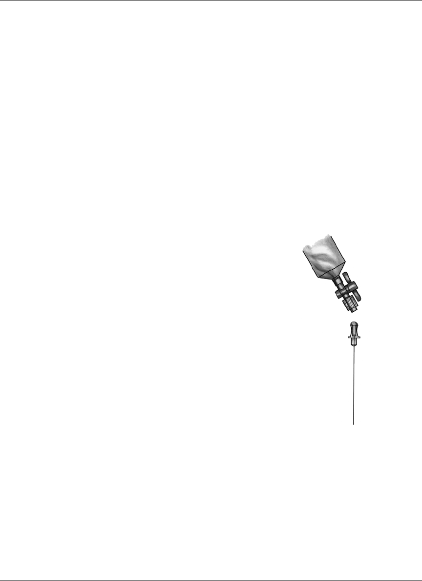
Pump implantation 55
Remove shipping fluid from the Pump
1. Using aseptic technique, open the Pump sterile package. Do not remove the
plastic tubing from the Pump outlet. Trim the distal part of the tubing with
the scalpel blade.
2. Remove the refill syringe from the refill kit package.
3. Firmly attach the two-way stopcock to the refill syringe and attach an 18
gauge needle to the stopcock.
4. Draw approximately 4 mL of RINSE BUFFER into the refill syringe.
5. Fill the hub of the refill needle with RINSE
BUFFER and firmly attach it to the
stopcock, prime the needle and close the
stopcock. (See Figure 6.)
6. Retract the plunger until it locks into place.
This should be no further than 55 mL. Do
not go beyond the vent hole. Press the lock
into the plunger groove to be sure it is firmly
secured.
7. Fill one 3 mL syringe with RINSE BUFFER
(RB) and attach a needle.
8. Fill the Pump fill port using the 3 mL
syringe. Any time a refill needle is to be
inserted into the Pump fill port, a fluid
barrier must be present to prevent air from
entering the Pump reservoir.
9. With the stopcock still closed, insert the RB
syringe into the Pump fill port.
10. Open the stopcock and allow the syringe
vacuum to empty the Pump of shipping
fluid. Allow 30 seconds after the fluid level
appears to have stopped rising in the refill
syringe, to assure the Pump is completely
emptied. Close the stopcock and remove the
syringe.
Figure 6: Filling the
hub of the refill needle

Pump implantation
56
Rinse the Pump with insulin (IN1)
1. Remove the second refill syringe from the refill kit package.
2. Firmly attach the two-way stopcock to the refill syringe and attach an 18
gauge needle to the stopcock. Use the sterile marker to label the syringe,
“IN1”.
3. Draw 20 mL of INSULIN (two vials) into the refill syringe.
4. Remove the 18 gauge needle and expel all air bubbles in the syringe.
5. Close the stopcock.
6. Retract the plunger until it locks into place. This should be no further than 55
mL. Do not go beyond the vent hole. Press the lock into the plunger groove to
be sure it is firmly secured.
7. Shake vigorously for a minimum of 30 seconds to degas the INSULIN.
8. Point the syringe tip upward and slowly open the stopcock to vent the
syringe.
9. Release the locking ring on the refill syringe.
10. Expel air in the syringe and carefully observe to ensure no air bubbles remain
in the syringe. If air bubbles are noted, repeat steps 5-10.
11. Fill the hub of the refill needle with INSULIN and attach it to the stopcock.
12. Prime the needle and close the stopcock.
13. Refill the fill port with the 3 mL RINSE BUFFER syringe, as needed, to
maintain the fluid barrier.
14. Use the “IN1” syringe containing the degassed INSULIN to fill the Pump.
OPTIONAL
Use these steps only if the plunger is not moving forward while filling the reser-
voir.
1. With the refill needle pointing down, vent the syringe head space by pulling
back firmly on the plunger until the second sealing ring on the black rubber
cap passes beyond the vent hole (see Figure 7).
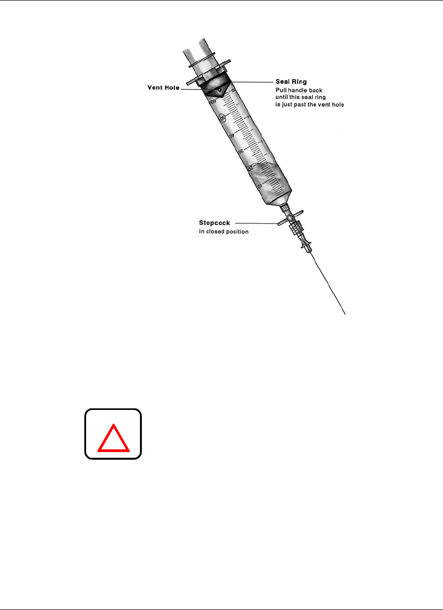
Pump implantation 57
Figure 7: Venting the syringe head space
2. With the stopcock closed, insert the refill needle into the Pump fill port.
3. Open the stopcock. Maintain downward pressure on the barrel of the syringe
to ensure the inlet valve of the Pump remains open.
Never push on the refill syringe plunger to fill the
Pump. When the refill needle is properly seated in
the fill port of the Pump, the vacuum in the reser-
voir will draw the insulin from the syringe.
4. Allow the Pump vacuum to draw the INSULIN into the reservoir. When the
INSULIN stops moving, the Pump is filled. Close the stopcock and remove
the syringe.
5. Prepare the IN1 syringe for aspiration. Remove any air from the syringe,
prime the needle, close the stopcock and obtain a vacuum by pulling back on
the plunger until it locks. Press the lock into the plunger groove to be sure it
is firmly secured. A fluid barrier of at least 2 mL should remain in the
syringe.
!
WARNING

Pump implantation
58
6. Insert the refill needle back into the Pump fill port with the stopcock closed.
7. Open the stopcock and empty the Pump. Allow 30 seconds after the
INSULIN level appears to have stopped rising in the refill syringe to assure
the Pump is completely emptied.
8. Close the stopcock and remove the syringe.
Fill the Pump with insulin
1. Remove another refill syringe (IN2) from a refill kit package.
2. Firmly attach the two-way stopcock to the refill syringe and attach an 18
gauge needle to the stopcock. Label the syringe IN2.
3. Draw 20 mL of INSULIN (two vials) into the IN2 syringe.
4. Remove the 18 gauge needle and expel all air bubbles in the syringe.
5. Close the stopcock.
6. Retract the plunger until it locks into place. This should be no further than 55
mL. Do not go beyond the vent hole. Press the lock into the plunger groove to
be sure it is firmly secured.
7. Shake vigorously for a minimum of 30 seconds to degas the INSULIN.
8. Point the syringe tip upward and slowly open the stopcock to vent the
syringe.
9. Release the locking ring on the refill syringe.
10. Expel the air in the syringe and carefully observe it to ensure no air bubbles
remain in the syringe. If air bubbles are noted, repeat steps 5 - 10.
11. Fill the hub of the refill needle with INSULIN and attach it to the stopcock.
12. Prime the needle and close the stopcock.
13. Place a sterile beaker or sterile barrier towel on the scale and tare it (position
balance at 0.)
14. Weigh the refill syringe and record the weight on the Implant Worksheet.
15. Insert the refill syringe into the Pump fill port, open the stopcock and allow
the Pump vacuum to draw INSULIN into the reservoir until the fluid level
stops moving. Close the stopcock.

Pump implantation 59
16. Remove the IN2 syringe and prepare for aspiration without expelling any
fluid. Obtain a vacuum by pulling back on the plunger until it locks. Press the
lock into the plunger groove to be sure it is firmly secured.
17. Reenter the Pump fill port with the stopcock closed.
18. Open the stopcock and withdraw 2 mL in order to activate the negative
pressure safety feature of the Pump. Close the stopcock and remove the
syringe.
19. Weigh the IN2 syringe to calculate the Pump refill amount. Subtract the
weight after the fill and 2 mL withdrawal from the weight before the fill and
record the difference on the Implant Worksheet.
Measure stroke volume
1. Place the PPC in the sterile bag. Enter the Supervisor Mode. The screen
displays “PUMP REFILL”. Press ACT until the “SET REFILL AMOUNT”
screen appears. When filling the Pump for the first time, set the
“EXTRACTED AMOUNT” to zero. Otherwise, enter the amount of insulin
extracted. Then use the and buttons to enter the refill amount from the
Implant Worksheet. Program the Pump.
2. Again, enter the Supervisor Mode and program “STOP PUMP”. From the
screen “PUMP STOPPED”, press SEL. “PUMP STOPPED” will begin
flashing. Press both the and buttons at the same time, until the screen
changes to the password screen. Reenter the password and the screen will
change to “PUMP REFILL.” Press SEL to reach the “PRIMING” screen.
“NO” will be flashing. Use the and buttons to select “YES,” then press
ACT. When the word “CONFIRM” is highlighted, press ACT again. Place
the PPC near the Pump to complete the communication process. Record the
time the priming bolus was initiated on the implant worksheet.
3. Listen for five beeps and observe that fluid is being pumped from tubing
attached to the Pump outlet.
4. Attach the 18 gauge needle (from the 3 ml syringe filled with RINSE
BUFFER) to the plastic tubing from the Pump outlet.
5. Remove the 3 ml syringe and fill the needle hub.
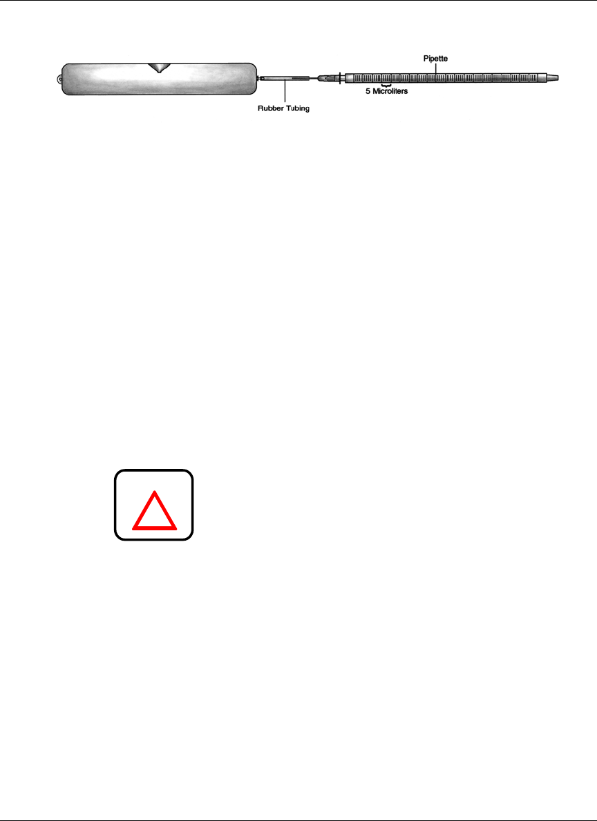
Pump implantation
60
Figure 8: Testing Pump stroke volume with a pipette
6. Insert the pipette into the hub. A meniscus of fluid will be present in the
pipette. This should be done on a flat surface with the pipette/tubing
assembly horizontal (see Figure 8).
7. Note the exact location of the fluid meniscus in the pipette.
8. Measure the stroke volume by noting the volume displaced by a minimum of
10 pulses. Record the total volume delivered and the number of pulses on the
Implant Worksheet. Divide the total volume delivered by the total number of
pulses used to deliver that volume. The volume per stroke must be between
0.40 and 0.60 µL. Record this value on the Implant Worksheet.
Prepare the Side Port Catheter
The Side Port Catheter (“Catheter”) is attached to the Pump before implantation;
however, it must be primed with INSULIN and inspected before being attached
to the Pump.
Never insert a needle into the connector end of the
Catheter for priming or for testing. There is a preci-
sion sealing surface in the connector that may be
damaged by the insertion of any needle.
1. Keep the Catheter in its package until the Pump is prepared and stroke
volume has been verified. Remove the Catheter from its sterile package and
document the serial number on the Implant Worksheet.
2. Using the last insulin syringe (IN2) from the Pump preparation procedure,
enter the Catheter port cone and push a small volume of insulin out of the
connector end of the Catheter. This primes the proximal portion of the
Catheter and cleans any debris from the connector outlet. Remove the
syringe.
!
WARNING
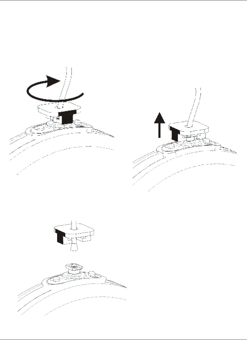
Pump implantation 61
3. (See Figure 9.) Remove the plastic tubing and tubing retainer from the Pump
outlet. Remove the tubing retainer by rotating it one-quarter turn clockwise to
disengage it from the connector flange. Then lift and remove the tubing and
retainer together from the Pump outlet. Dispose of the tubing and retainer.
Figure 9: Tubing and retainer removal
View A
Rotate tubing retainer
View B
Pull tubing retainer
off pump
View C
Tubing and retainer
removed
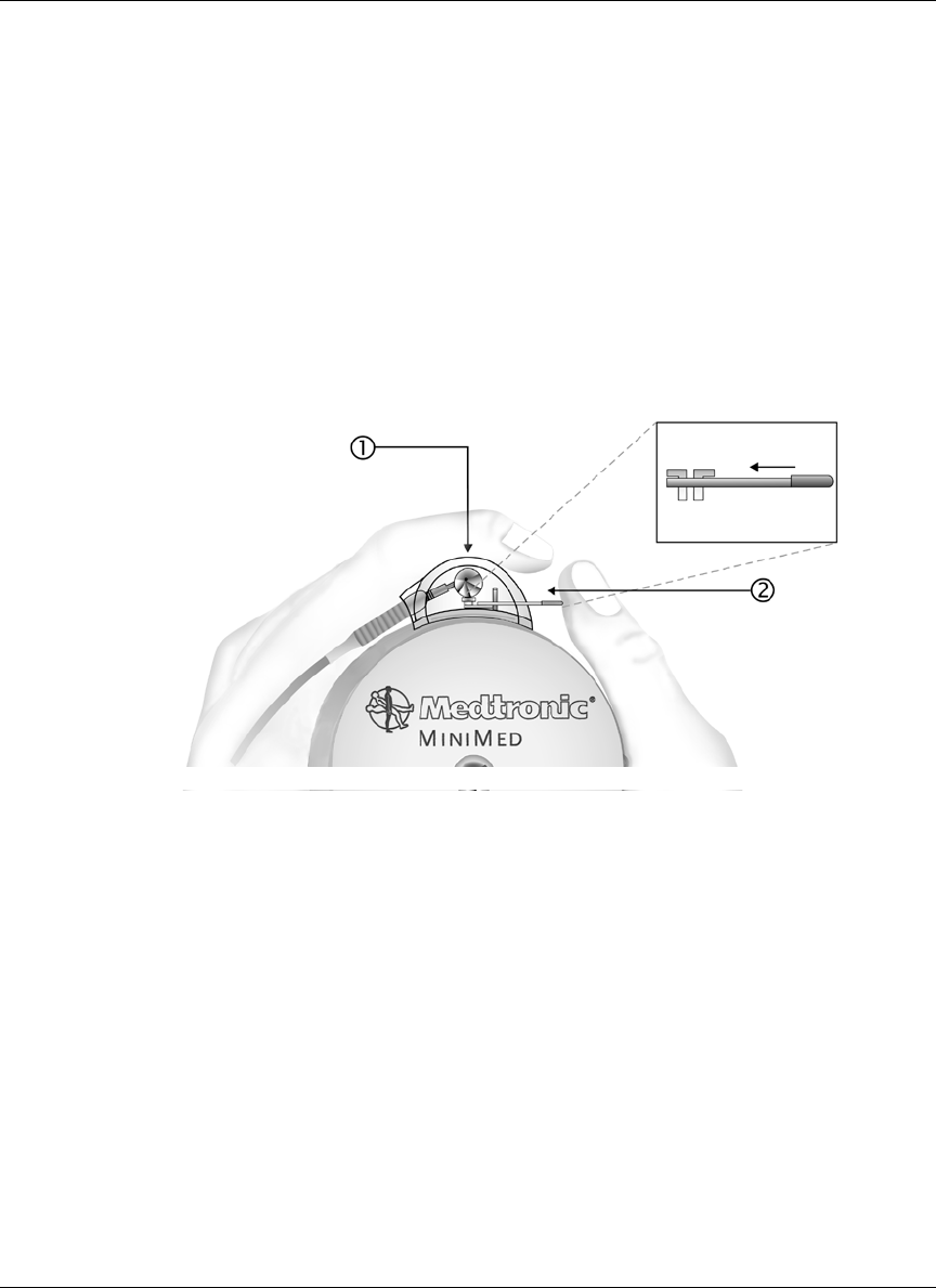
Pump implantation
62
4. Inspect the outlet of the Pump for debris. Debris, especially fibers, left in the
fluid path will compromise the function of the Catheter check valve. Rinse
the outlet tube of the Pump with water from a syringe, if necessary. Avoid
wiping the Pump with gauze or drapes that will leave fibrous debris.
5. Pull the locking bar out and gently push the Catheter straight down onto the
Pump outlet. Never twist the connector.
6. Only after the Catheter is seated, squeeze the connector (see Figure 10, item
1), firmly against the Pump between the thumb and forefinger of one hand.
Then push the locking bar (item 2) into place with the thumb of the other
hand.
Figure 10: Proper attachment of the Side Port Catheter to Pump
7. Verify the Catheter is securely attached to the Pump. Look into the connector
and observe the position of the locking bar with respect to the Pump
connector outlet. Check the side port connector hub for abnormalities (e.g.,
cracks, misalignment.)
8. Using the IN2 refill syringe, enter the Catheter side port cone and push a
small amount of INSULIN out the Catheter tip. Verify that no insulin flow is
observed at the Pump/Catheter interface. Remove and reseat the Catheter if
flow is noted. Remove the syringe.
9. Confirm insulin delivery from the tip of the Catheter and note it on the
Implant Worksheet. The INSULIN will form a dome on the tip of the
Catheter. Pulsatile delivery will not be obvious. If the priming bolus has
already ended, program an immediate bolus (about 20 units) to confirm
delivery. (This bolus may be canceled after delivery is verified.)

Pump implantation 63
10. At the end of the bolus, rinse the outside of the Pump thoroughly with sterile
water to remove traces of INSULIN. The Catheter tip should not be placed in
the water. Protect the Pump with sterile drapes until the surgeon is ready to
implant it. Verify that the priming bolus is finished or canceled prior to the
implantation.
The Pump and Catheter are now ready for implantation.

Pump implantation
64
Performing the surgical procedure
Pre-operative evaluation
The Pump implant depth should not exceed 5 cm (2 inches) beneath the surface
of the skin. If the Pump is implanted too deeply in the subcutaneous tissue it may
be difficult to access the refill port.
Formation of the pump pocket
Pump implantation can be performed either under local or general anesthesia.
After satisfactory anesthesia, a pre-selected abdominal site is prepped and draped
in the customary surgical method.
A transverse or longitudinal incision is made and deepened through the skin and
subcutaneous tissue. Care should be taken in choosing the location of the incision
so the suture line is next to but not over the Pump inlet fill port or the Catheter
side port. A subcutaneous blunt dissection is performed to create a pocket large
enough to accommodate the Pump. Meticulous hemostasis should be established
with electrocautery.
The Pump is secured to the fascia of the abdominal musculature using the three
suture tabs provided. Securing the Pump with all three suture tabs is recom-
mended, as it will prevent migration, rotation or inversion in the pocket and pos-
sible dislodgment of the Catheter.
Figure 11 indicates a possible Pump placement and corresponding incision sites.
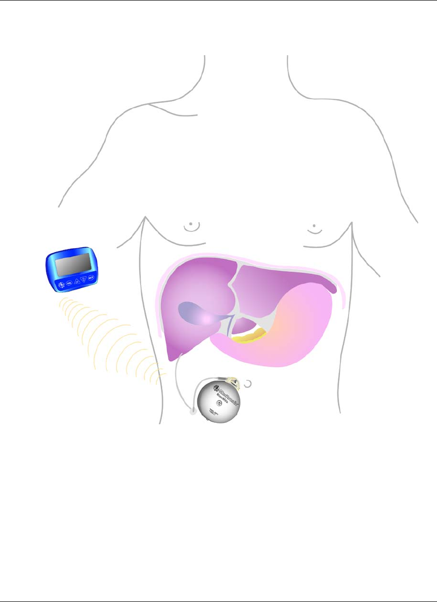
Pump implantation 65
Figure 11: Example of Pump placement

Pump implantation
66
Catheter placement
The Catheter is not designed to be tunneled subcutaneously. The Catheter inser-
tion should be at the extreme edges of the Pump pocket.
At a site not directly beneath the Pump, the layers of abdominal musculature are
divided to expose the peritoneum. Concentric purse string sutures are placed and
the peritoneum is exposed with a 1 cm incision. The distal tip of the Catheter is
placed in the peritoneal space. The flange of the Catheter is sutured firmly to the
fascia of the abdominal musculature. Sutures should only be placed on the rein-
forced flange of the Catheter. Sutures must not be placed directly on the Catheter
itself.
Never trim or cut the tip of the Catheter.
The implant site should be irrigated with an antibiotic solution. Interrupted
absorbable sutures should be used to approximate the subcutaneous tissues and
the skin closed with a running subcuticular absorbable suture. The wound is
dressed using standard surgical technique. At the end of the surgery, place an
abdominal binder over the implant site. This binder must be worn until the cap-
sule has formed (about 1 month.) The binder is recommended because it will
obtain a better cosmetic result and minimize the post operative swelling.
!
WARNING

Pump implantation 67
Post-operative management
Post-operative hospitalization
After implantation, the surgical incision should be inspected for any signs of
unusual swelling, tenderness, pain, or drainage. Potential post-operative compli-
cations include Pump pocket seroma, wound dehiscence, wound infection, and
catheter dislodgment.
Length of post-operative hospitalization depends upon how rapidly the patient
adjusts to the Pump and how quickly blood glucose levels
stabilize. During post-operative hospitalization, the Pump can be reprogrammed
to accommodate the needs of the patient. As post-operative stress decreases,
insulin requirements may decline. It may be necessary to make several changes
in insulin delivery rates during the first few days following implantation.
Patients must be thoroughly educated in all aspects of follow-up care with the
Pump. The Medtronic MiniMed Patient Manual should be used to supplement
patient education. Prior to discharge, patients should:
• Fully understand how to use their PPC;
• Know what to do in the event of Pump or PPC difficulties;
• Have scheduled their first refill appointment;
• Have set an appointment for their first follow-up visit;
Post-operative x-rays
The Catheter has been designed with a radio-opaque stripe for identification after
implantation. A lateral and anterior X-ray is recommended after implantation to
locate and document the position of the Catheter. This radiograph should be kept
with the patient’s records for future reference.

Pump implantation
68

69
CHAPTER 5 Pump refill procedure
Introduction
Initial appointments for Pump Refills should be made with patients at the time of
implantation. Subsequent appointments should be made in advance, normally
during each refill procedure. The Pump stores approximately 6,000 units of insu-
lin medication and typically requires a refill every two to three months. In order
to maintain the physical stability of the insulin, the Pump must be refilled at a
maximum interval of no more than 90 days. The PPC will display warning mes-
sages to alert the patient of calculated low or emptied reservoir volumes.
The low reservoir message will appear when the PPC calculates that 800 (2 ml)
or fewer units of insulin medication remain in the Pump. The empty reservoir
message will appear when the PPC calculates that 400 or fewer units (1 ml) of
insulin remain. The time to medication depletion depends upon the insulin deliv-
ery rate of the Pump.
The Pump refill procedure should always be sched-
uled in advance of PPC “low reservoir” or “empty
reservoir” messages.
!
WARNING

Pump refill procedure
70
Supplies and solutions
The refill kit (MMT-4105) is intended exclusively for use with the
Medtronic MiniMed 2007D Implantable Insulin Pump System. The refill kit con-
sists of a specially designed syringe and stopcock for removing fluids from and
placing fluids into the Pump. Use only refill needles (MMT-4102) available from
Medtronic MiniMed to perform all Pump refill procedures. This 22 gauge needle,
featuring a rounded, lubricated tip and a beveled side hole, has been specially
developed to mate with the Pump fill port.
Use of other needles may result in damage to the
Pump septum in the fill port, and may allow body
fluids to enter the Pump.
Below is a list of the supplies and solutions necessary to perform the refill proce-
dure:
Supplies:
• Steri-Strips® and Markers
• The Patient’s PPC, Glucose Monitoring Equipment, Drapes
• One (1) Scale (0.01 gram resolution)
• One (1) 250 ml Sterile Beaker
• One (1) Port Locating Template - MMT-4106
• Two (2) Refill Kits - MMT-4105 - Three (3) Medtronic MiniMed MMT-
4102 Refill Needles (Extra needles should be available for use.)
• Four (4) 18 Gauge Regular Bevel Needles
Solutions:
• One (1) 10 ml Vial, Rinse Buffer Solution, MMT-2008
• Two (2) 10 ml Vials, U-400 Insulin, stored at room temperature for a
minimum of 10 hours prior to surgery.
!
WARNING

Pump refill procedure 71
Prepare for pump refill
NOTE: Before beginning any refill, rinse, flush, or pressure
measurement procedure, carefully read Appendix D,
Precautions and General Procedures.
Never push on the refill syringe plunger to fill the
Pump. When the refill needle is properly seated in
the Pump fill port, the vacuum in the Pump reser-
voir will draw the insulin from the syringe into
the reservoir.
To prepare for emptying and refilling the Pump, perform the following steps:
• Use the “HISTORY” feature of the PPC to determine the amount of insulin
medication remaining in the Pump. Make sure that ACT is pressed on the
“READ PUMP DATA” screen to update PPC history from the Pump.
Record this value on the refill worksheet (Appendix C).
• Prepare a sterile field. The physician should scrub, mask and glove for the
refill procedure. Refilling the Pump is an aseptic procedure.
• (See Appendix D, Precautions and General Procedures.)
• Aseptic skin preparation of the patient’s Pump refill site should be
performed using your institution’s standard operating procedures.
!
WARNING

Pump refill procedure
72
Perform the refill procedure
Fill out the refill form
Fill out the top part of the Refill Form (Appendix C) with the patient’s I.D., refill
date, insulin lot number, previous refill volumes, insulin medication remaining,
and the name of the person performing the refill procedure. This information can
be helpful for diagnostic purposes.
Label syringes
Use a sterile marker and Steri-Strips® to label one refill syringe “RB” (rinse
buffer syringe) and the other “IN” (insulin syringe).
Prepare the refill syringe for emptying the Pump
1. Firmly attach a stopcock to the RB syringe and
attach the 18 gauge needle to the stopcock.
Check connections to ensure they are secure.
Draw 5 ml of Rinse Buffer into the RB refill
syringe.
2. Expel all air bubbles from the refill syringe.
Remove the 18 gauge needle from the
stopcock.
3. Fill the hub of the refill needle with Rinse
Buffer from the RB refill syringe and attach it
to the stopcock. (See Figure 12) Prime the refill
needle completely. Close the stopcock.
4. Obtain the weight and record it on the Refill
Form. Set the syringe aside.
Figure 12: Filling the
hub of the refill needle

Pump refill procedure 73
Prepare the refill syringe for filling the Pump
1. Firmly attach a stopcock to the IN refill syringe and attach an 18 gauge
needle to the stopcock. Draw 20 ml of U-400 insulin into the syringe.
2. Expel all air from the refill syringe. Close the stopcock and remove the 18
gauge needle.
3. Retract the plunger until it locks into place. This should be no further than 55
ml - do not go beyond the vent hole. Press the lock into the plunger groove to
be sure it is firmly secured.
4. Shake vigorously for a minimum of 30 seconds.
5. Point the syringe tip upward and slowly open the stopcock to allow air to
enter the syringe.
6. Release the locking ring on the refill syringe. With the syringe pointed
upward, push on the plunger to expel the air and prime the stopcock.
7. Open the stopcock and prime the refill needle. Attach the refill needle to the
stopcock. Close the stopcock.
8. Inspect the syringe to ensure there are no air bubbles. If air bubbles are noted,
remove the refill needle and repeat steps 2 - 8.
9. Weigh the IN syringe and record on the refill form.
10. Set the syringe aside.
Empty the Pump
1. Obtain a vacuum in the RB syringe by pulling back on the plunger until it
locks. Press the lock into the plunger groove and be sure it is firmly secured.
2. Locate the fill port by centering the template over the Pump. The center hole
in the template should be directly over the Pump fill port. Insert the 18 gauge
guide needle into the Pump fill port. Local anesthesia may be used prior to
insertion of the 18 gauge needle.
3. Press the primed refill needle (attached to the RB syringe) into the Pump fill
port, by sliding it through the 18 gauge guide needle. Pull back slightly
(approximately 2 mm) on the guide needle to allow the refill needle to enter
the Pump fill port and actuate the inlet valve.(See Figure 13)
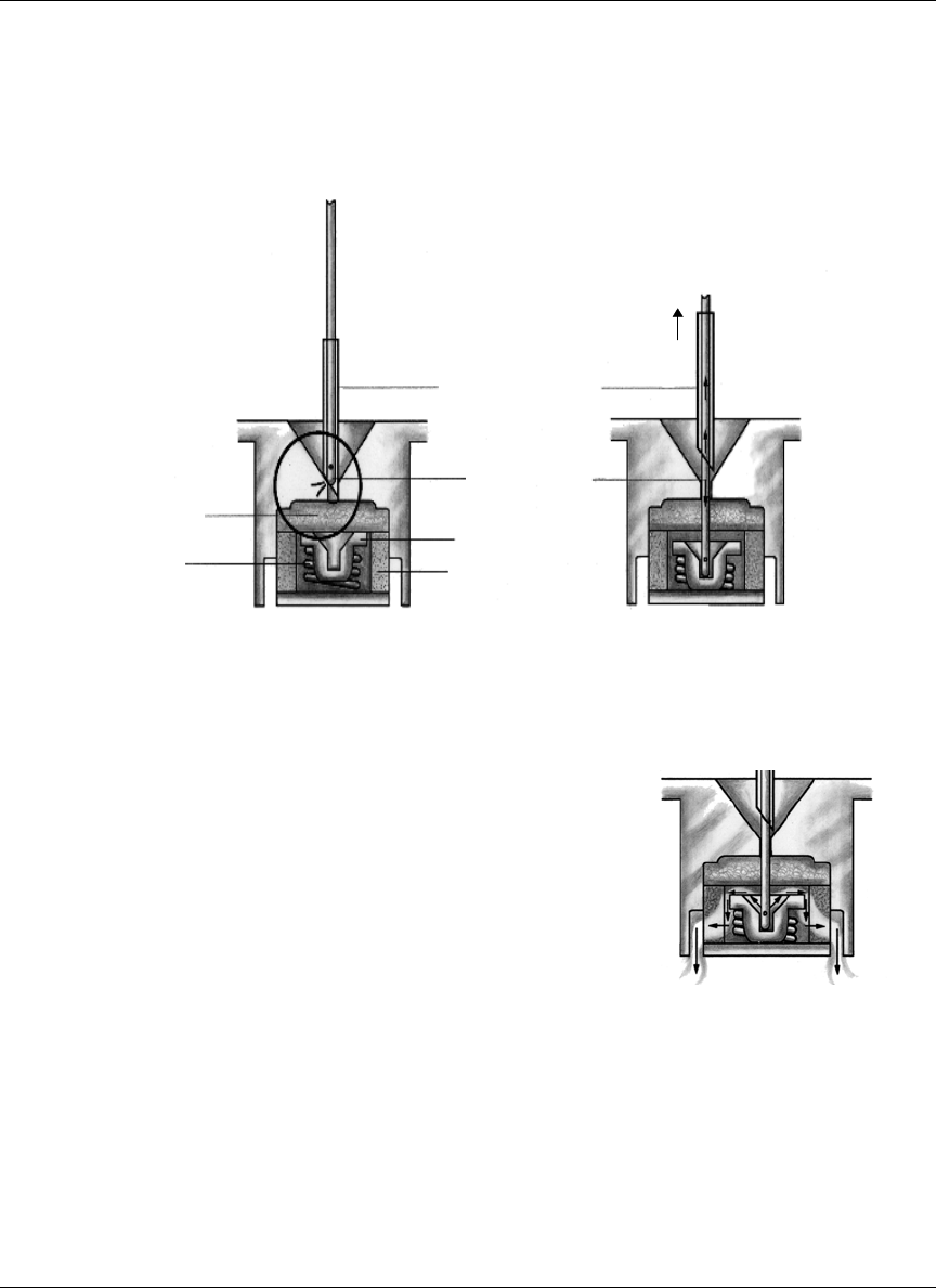
Pump refill procedure
74
Figure 13: Operation of the Pump inlet valve
18G Guide Needle
Refill Needle
Valve
Filter
Septu
m
Spring
2mm
Step 3A
Step 3B
Step 3C
Step 3A: Locate the port using the 18G guide
needle slide the refill needle down the
guide needle.
Step 3B: Pull back approximately 2mm on the
guide needle to enter the Pump.
Step 3C: Apply firm pressure to move the valve
back and allow the insulin to pass above
the valve through the filter and into the
reservoir.

Pump refill procedure 75
4. Actuate the valve by applying a gentle downward force on the refill needle.
This depresses the valve approximately 0.5 mm.
5. Open the stopcock and allow residual insulin from the Pump to be drawn into
the RB refill syringe. Maintain a downward pressure on the syringe to ensure
that the inlet valve in the Pump remains open. Wait 30 additional seconds
after the insulin level appears to have stopped rising in the RB refill syringe
to ensure the Pump is completely emptied.
6. When all residual insulin is withdrawn from the Pump, close the stopcock.
Remove the RB refill syringe.
NOTE: Do not remove the 18 gauge guide needle.
7. Weigh the RB syringe and record on the refill form.
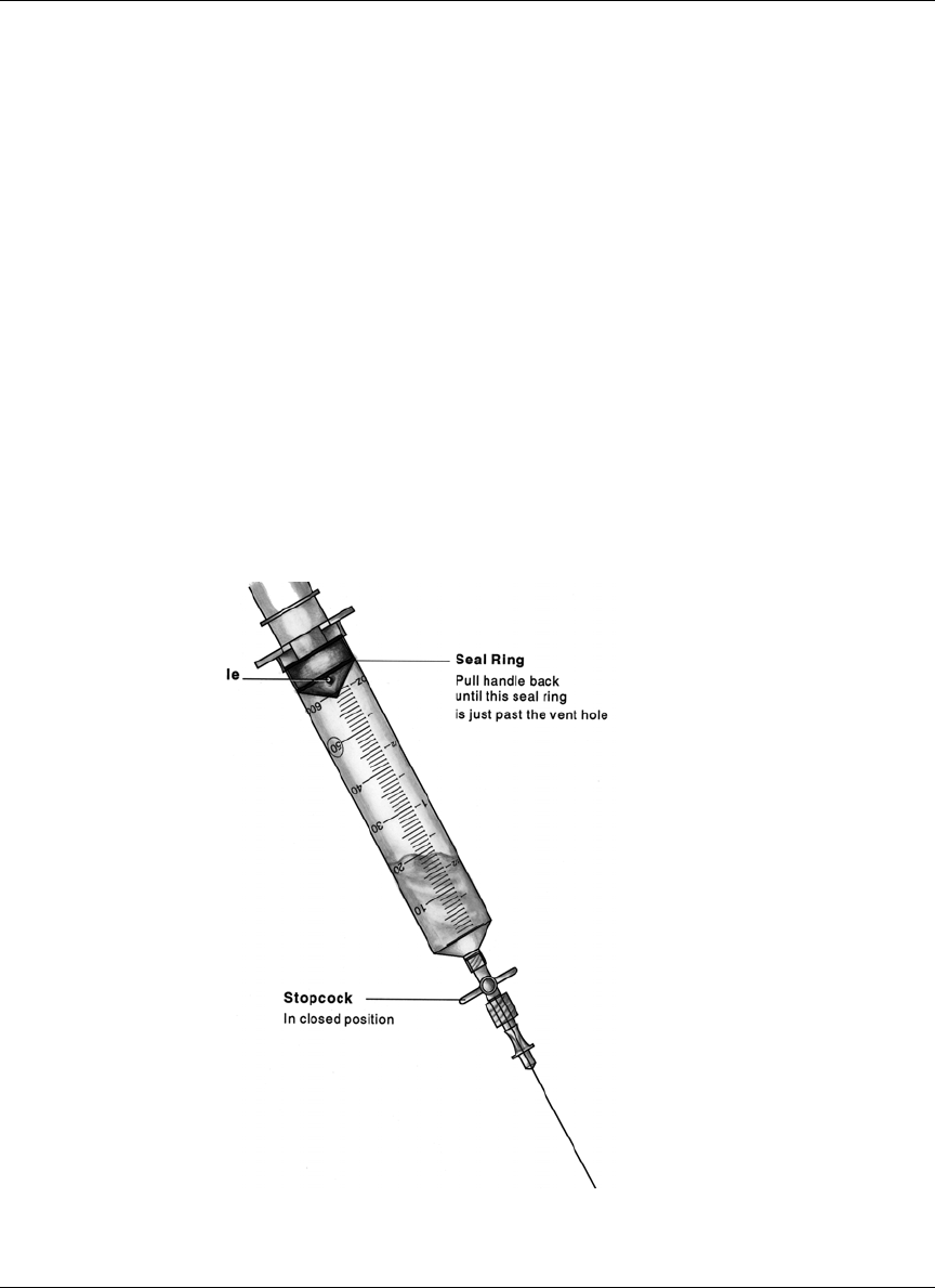
Pump refill procedure
76
Refill the Pump
1. Use the IN refill syringe containing 20 ml of degassed insulin, at room
temperature.
2. Enter the Pump by passing the refill needle with the attached IN refill syringe
through the 18 gauge guide needle. Pull back slightly (approximately 2 mm)
on the 18 gauge needle to allow the refill needle to enter the Pump and
actuate the inlet valve (see Figure 13).
3. Open the stopcock. Maintain downward pressure on the IN refill syringe to
ensure the inlet valve in the Pump remains open. Allow the Pump to draw in
insulin until the fluid level stops moving. Close the stopcock.
4. Remove the IN syringe and prepare for aspiration without expelling any fluid
by pulling back on the plunger until it locks. Re-enter the Pump, open the
stopcock and withdraw 2 ml in order to activate the negative pressure safety
feature of the Pump.
OPTIONAL
Use this step only if the
plunger is not moving
during the fill of the
reservoir.
With the refill needle
pointing down, vent the
syringe head space by
pulling back firmly on the
plunger until the second
sealing ring on the black
rubber cap passes beyond
the vent hole (see Figure
14).
Figure 14: Venting the Medtronic MiniMed refill syringe

Pump refill procedure 77
5. Remove the IN syringe. Remove the 18 gauge needle and apply pressure to
the insertion site.
6. Weigh the IN syringe and record on the Refill Form.
Calculate extracted and refill amounts
1. Calculate the extracted amount by using the calculation section of the refill
form.
2. Calculate the refill amount by using the calculation section of the refill form.
3. Enter the extracted amount (amount withdrawn as calculated on the refill
worksheet at line E) and the refill amount (as calculated on the refill
worksheet at line G) into the PPC.
Calculate refill accuracy
The PPC automatically calculates the refill accuracy following the PPC refill pro-
gramming. You can also follow the calculation section of the refill form to calcu-
late the refill accuracy.
Enter the refill accuracy value (in %) on the line provided on the refill form. It is
important to record this value to evaluate system function.

Pump refill procedure
78

79
CHAPTER 6 Explanting the Pump
System
Explant considerations
When the battery in the Pump is depleted or if acceptable glycemic control can-
not be achieved, it may become necessary to explant the Pump system.
Prior to explantation, it may be possible to perform interventions that could cor-
rect certain conditions. These procedures are described in Appendices E and F.
If all appropriate interventions have been exhausted without an acceptable out-
come, please contact Medtronic MiniMed prior to scheduling a Pump explanta-
tion.
Returning devices/components to Medtronic
MiniMed
Explanted Pumps and Catheters or other components should be returned to
Medtronic MiniMed for evaluation. Please call Medtronic MiniMed and obtain a
Returned Sales Order (RSO) number prior to each return.
Explanted devices must be sealed in an appropriate biohazard container and
packed with a gauze pad soaked with sterile saline. The shipping container
should be water tight. Chemical and reliability analysis require that the device
not dry out during transportation.
Be certain to include required patient information as well as the RSO number,
date, and reason for the explant and place all pertinent documentation in a water
tight document package. Put the RSO number on the shipping label.

Explanting the Pump System
80
Please take the necessary precautions when shipping the Pump System via com-
mercial carrier to avoid damage to the Pump. Please return explanted Pump Sys-
tems to:
United States:
Medtronic MiniMed
18000 Devonshire Street
Northridge, CA 91325
Telephone: 1-818-576-5555
Europe:
Medtronic EOC
Earl Bakkenstraat 10
6422 PJ Heerlen
Netherlands
Tel 3 145 56 68 000
or

81
CHAPTER 7 Warnings and precautions
Warnings
The Physician should be completely familiar with the function of the Pump,
Catheter, and PPC prior to use. Patients should be provided a complete copy of
the Patient Manual and have demonstrated the ability to program the PPC,
recognize and respond to safety alarms, and take care of the device prior to
discharge.
Only special U-400 insulins specifically labeled for use with the Medtronic
MiniMed Insulin Infusion Systems may be used in the Medtronic MiniMed
2007D Implantable Insulin Pump. Use of other insulin types may cause damage
to the Pump mechanism resulting in impaired insulin delivery or Pump failure.
Any unauthorized changes or modifications made to any component of the
Medtronic MiniMed 2007D Implantable Insulin Pump System may prevent
effective use of that and other components.
Electrotherapy
The Medtronic MiniMed 2007D Implantable Insulin Pump System has been
tested in close proximity with electrosurgical, electrocoagulation, and cardiac
defibrillation medical equipment. Typical use of this type of device has not
affected the Pump. However, patients should be instructed to test Pump function
(e.g., self test) after such procedures to determine that the Pump and PPC are
operating properly. If the system is not performing correctly, contact Medtronic
MiniMed.

Warnings and precautions
82
Diagnostic ultrasound
The Medtronic MiniMed 2007D Implantable Insulin Pump System has been
tested during diagnostic ultrasound procedures. These procedures have no effect
on Pump performance. However, patients should be instructed to test the Pump
function (e.g., self test) after such procedures to determine that the Pump and
PPC are operating properly. If the system is not performing correctly, contact
Medtronic MiniMed.
Ultrasound therapy
The Medtronic MiniMed 2007D Implantable Insulin Pump System should not be
exposed to therapeutic ultrasound procedures such as lithotripsy. Exposure to
ultrasound therapy may damage the Pump, and not be immediately apparent.
Diagnostic radiation
The Medtronic MiniMed 2007D Implantable Insulin Pump System has been
tested during diagnostic radiation procedures, such as Computed Tomography
and X-ray. These procedures have no effect on Pump performance. However,
patients should be instructed to test the Pump function (e.g., self test) after such
procedures to determine that the Pump and PPC are operating properly. If the
system is not performing correctly, contact Medtronic MiniMed.
Elevated anti-insulin antibodies
The results of clinical investigations suggest a small population of patients may
develop anti-insulin antibodies when using the Medtronic MiniMed 2007D
Implantable Pump System and U-400 insulin. Patients with multiple autoimmune
disorders may be more susceptible to developing high titers of anti-insulin
antibodies, which in turn may cause symptoms. There was no correlation
between length of exposure to the study drug and the resultant titer of anti-insulin
antibodies. Elevated levels of anti-insulin antibodies alone have been proven not
to interfere with diabetes management using continuous intraperitoneal insulin
infusion with this system.

Warnings and precautions 83
Environmental conditions
The Medtronic MiniMed 2007D Implantable Insulin Pump System should not be
exposed to extreme electrical or magnetic fields. Although it is not possible to
include every environmental condition that may affect the Pump, most are listed
below. Please contact Medtronic MiniMed when in doubt if certain
environmental exposure will affect the pump.
DO NOT EXPOSE THE MEDTRONIC MINIMED
2007D IMPLANTABLE INSULIN PUMP SYSTEM
TO ANY OF THE FOLLOWING CONDITIONS:
• Magnetic Resonance Imaging (MRI) Procedures.
• Lithotripsy Treatment.
• Large Rotating Magnetic Fields - Refers to large industrial rotating
magnetic fields, such as those found in Industrial Power Plants.
• Magnets Held Directly Over the Pump.
• High Power Radio or Satellite Transmitting Towers.
• Altitudes Above 2,400 meters (8,000 feet).
• Therapeutic Ultrasound
• Therapeutic Radiation
The Medtronic MiniMed 2007D Implantable Insulin Pump System is not
designed for use at elevations above 2,400 meters (8,000 feet). Use of the Pump
System at higher elevations may result in insulin over delivery, which may cause
personal injury or death. Therefore, patients who live at elevations above 2,400
meters (8,000 feet) should not use the Pump. Patients who use the Pump and who
plan to travel to an elevation above 2,400 meters (8,000 feet) should first have
their Pump reservoir emptied of insulin, and they must self-administer insulin by
other means for the duration of the trip and until their Pump reservoir is refilled
again.
(This warning does not apply to travel on commercial aircraft because normal
cabin pressurization is adequate to ensure proper operation of the Pump.)
• Diving Below 7.6 Meters (25 Feet).
• Physical Damage to the Pump or Pump Pocket.
!
WARNING

Warnings and precautions
84
Physicians should instruct patients to avoid any sharp blows or pressure directly
at the Pump location. A direct hit by an object such as a baseball may damage the
Pump and/or injure the Pump pocket. Extreme pressure on the Pump may cause
the sutures and the tissue pocket to be damaged. As a result, the Pump may move
from its pocket and possibly dislodge from the Catheter.
If the Pump has been damaged by such a blow, the patient should be instructed to
contact their physician. Physicians may order a pressure bandage or a reduction
in the patient’s physical activity until the pump pocket reheals completely.
• Exposure to Extreme Body Temperatures
Exposure to elevated body temperatures in excess of 104°F (40°C) will
compromise the negative pressure reservoir safety feature of the Medtronic
MiniMed 2007D Implantable Pump. Glucose levels should be monitored closely
if this occurs.
Sterilization
The Pump, Catheter and the refill kit are sterilized with ethylene oxide (EtO).
The Pump System is NOT Reusable.
If the sterile package has been opened, damaged or tampered with DO NOT USE
the packaged device.
NOTE: Do Not Re-Sterilize the Implantable Insulin Pump
NOTE: Do Not Re-Sterilize the Side Port Catheter
NOTE: Do Not Re-Sterilize Components of the Refill Kit.
The Pipette (MMT-4104), may be resterilized using autoclave, EtO or according
to hospital procedures.
The Template (MMT-4106) may be resterilized using steam autoclave or EtO per
hospital procedure. This template is made from polycarbonate plastic and will
have a limited life in steam autoclave cycle. The template will not withstand dry
heat autoclave cycles.

Warnings and precautions 85
Precautions
Emergencies and the use of conventional insulin supplies
Physicians should advise patients who are implanted with the Medtronic
MiniMed 2007D Implantable Insulin Pump System how to deal with emergency
conditions such as hyperglycemia and hypoglycemia. Patients should always
carry conventional insulin supplies with them, including insulin and a means to
inject it, in the event of impaired insulin delivery by the Pump System. Delivery
of insulin can become impaired due to a failure of a Pump and/or PPC, or a
Catheter occlusion. Replacement of the Pump, PPC or Catheter may be required.
Physicians should review the Pump replacement and Catheter clearing
procedures in this Physicians Manual
PPC reliability requirements
The PPC is a sensitive electronic device, and can incur physical damage. If the
PPC is dropped or receives an impact patients should be instructed to
immediately perform a SELF TEST to check the displays for proper operation. If
the PPC does not display correctly, a replacement PPC is required. Patients
should initiate alternative diabetes management until a replacement PPC is
received.
The PPC housing is not watertight and it may malfunction if immersed in water.
“Condensing humidity” conditions such as steam rooms should also be avoided,
because condensation can also damage the PPC’s microelectronics. If either
situation occurs, contact Medtronic MiniMed immediately and arrange for the
repair or replacement of the PPC. If the PPC is accidentally splashed, sprayed or
immersed, remove excess moisture with a soft towel and then place the PPC in a
warm place to thoroughly dry. When dry, perform a “SELF TEST.” If the PPC
does not display correctly, call Medtronic MiniMed to replace the device.
Maximum dosages
The physician can program specific limitations to insulin Basal Rates and Bolus
amounts, as well as total daily insulin usage. These limitations provide some
control of patients’ ability to program their insulin regimens, and to avoid
overdosing.

Warnings and precautions
86
Electrical and magnetic fields
Common electrical and magnetic fields that do not affect the Pump include
microwave ovens, satellite receiving dishes, common household appliances,
security devices found in department stores and airports, standard medical X-
rays, cellular phone, and radiowaves.

87
CHAPTER 8 Adverse reactions
Adverse reactions
In clinical studies, adverse reactions associated with the Medtronic MiniMed
2007D Implantable Pump included hypoglycemia, diabetic ketoacidosis,
hyperglycemia, skin erosion, infection, abnormal healing, elevated anti-insulin
antibodies, intestinal obstruction, post-operative discomfort and pain. Pump
System malfunctions in order of frequency and seriousness include, insulin
aggregation resulting in insulin under-delivery, Catheter occlusion or tissue
overgrowth, premature depletion of the Pump battery, and failure of Pump
electronics. Adverse events associated with the use of U-400 insulin are
described in the package insert accompanying the insulin medication.
Prevention
The majority of adverse reactions in patients using the Medtronic MiniMed
2007D Implantable Pump System can be prevented by teaching patients
dependable blood glucose monitoring. The patient plays a significant role in
diagnosing and correcting Pump System performance problems. Should Pump
performance change, the patient would be able to detect a change in blood
glucose levels.
Patients should be instructed to contact their physi-
cian’s office, if they experience unresolvable difficul-
ties with the Pump System. Patient visits and
diagnostic procedures may be necessary to correct
these conditions.
!
WARNING

Adverse reactions
88

89
CHAPTER 9 System alarms and
messages
The Medtronic MiniMed 2007D Implantable Insulin Pump System is equipped
with various alarms and messages that ensure the correct function of the system.
The Implantable Insulin Pump alarm system will “beep” when certain conditions
occur. The beeps are designed to be audible through the skin and alert the patient
that the Pump needs attention. For severe alarm conditions the Pump will alarm 4
tones each minute for 10 minutes then, 4 double tones each minute for 10 min-
utes and repeat the pattern. Upon hearing the alarm, the patient must communi-
cate with the PPC, to determine the alarm condition. The alarm can be cleared by
pressing SEL then ACT. The following descriptions explain the alarm conditions
the system may encounter.
The PPC has three types of alarms: audible, vibrate and visual alarms. The chap-
ter will describe for each alarm condition, which screen message appears and the
vibrate or audible alarm associated with it.
Two audible or vibrate alarm types are used:
Alarm Type 1:
If the PPC is set to “vibrate”, the vibrator will be turned on for 3 seconds every
minute for 30 minutes.
If the PPC is set to “audible”, the PPC will beep 6 times every minute for 30 min-
utes. If the alarm is not cleared in 30 minutes, the PPC will beep 6 alternating
tones. The PPC will continue to do so every minute.
Alarm Type 2:
If the PPC is set to “vibrate”, the vibrator will be turned on for 3 seconds every
30 minutes while the condition exists.
If the PPC is set to “audible”, the PPC will beep 3 times every 30 minutes while
the condition exists.
Some alarms can be cleared by pressing SEL then ACT.

System alarms and messages
90
Pump alarms
Alarm feedback
The Alarm Feedback function allows the user to verify the Pump and Pump
alarm are operating normally. Physicians can also use Alarm Feedback to mea-
sure the time intervals between Pump strokes to verify accurate insulin delivery.
When Alarm Feedback is programmed “YES”, the Pump will beep on each of the
first five Pump strokes:
• Following a change in the delivery regimen, for example when completing
a meal Bolus and then changing to a Basal Rate, or at the start of a bolus.
• After the Alarm Feedback function is programmed “YES.” Alarm
Feedback will stay on until programmed back to “NO.”
Pump low battery
The Implantable Insulin Pump battery is designed to last approximately ten years
during conditions of normal use (see Chapter 11 for Technical Specifications).
Battery life may vary somewhat depending upon a user’s insulin delivery
requirements. When battery energy becomes low, a voltage sensor in the Pump
will trigger the Pump Low Battery Alarm. A Pump Low Battery Alarm indicates
there is approximately eight weeks of battery energy remaining.
The Pump Low Battery alarm can be cleared and the Pump will continue to oper-
ate normally. However, users should be instructed to report the alarm immedi-
ately to their physician. A Pump replacement or resumption of conventional
insulin therapy should then be scheduled.
Depleted pump battery
When there is no longer sufficient battery energy to power the Pump, the Pump
Low Battery Alarm will cease and insulin delivery will stop. Alternate insulin
therapy must be initiated.
PPC Display Type of Alarm Pump Alarm
PUMP
LOW BATTERY 1 In 24 hours if no PPC
communication

System alarms and messages 91
System error
The Implantable Insulin Pump has a sophisticated self-monitoring system that
periodically checks for circuit faults. If a fault should occur in the Pump electron-
ics, insulin delivery will stop. Conventional insulin therapy must be initiated
immediately. Notify Medtronic MiniMed immediately.
Pump self test fail
If during a “SELF TEST” the Pump presents a malfunction, the insulin delivery
will stop. Clear the message by pressing SEL then ACT. Notify Medtronic Min-
iMed immediately.
PPC low battery
If the PPC main battery (AA 1.5 volt alkaline) energy is low, the following alarm
display appears each time a new function is programmed:
Clear this message by pressing SEL and then ACT. While the battery should
have sufficient energy for a few additional programming commands, the battery
should be changed as soon as possible. For instructions on changing the battery,
(see Chapter 3, Personal Pump Communicator).
NOTE: If while programming the PPC, the screen goes blank, the
PPC beeps six times and then the “CHECK PUMP
STATUS” message appears, the battery needs to be
replaced. (See Chapter 3 for instructions, Install/Replace
the Main Battery).
PPC Display Type of Alarm Pump Alarm
PUMP STOPPED
1 or 2 or 3 or 4 or 5 or 6 1 In 5 minutes if no PPC
communication
PPC Display Type of Alarm
PUMP
SELF TEST FAIL 1
PPC Display Type of Alarm
PPC
LOW BATTERY 1

System alarms and messages
92
PPC alarms
The PPC offers a choice of two alarms, audible and vibrate. In addition, a screen
message appears indicating the type of alarm condition that occurred.
Low reservoir
When the Pump calculates that less than 800 units (2ml) of insulin remains in its
reservoir, the following display will appear:
Clear this message by pressing SEL and ACT. Users should be instructed to
report this alarm to their physician as soon as possible and schedule an appoint-
ment for a Pump refill.
Empty reservoir
When the Pump calculates that less that 400 units (1ml) of insulin remain in its
reservoir, the following display will appear:
Clear this message by pressing SEL and ACT, and then continue programming.
Users should be instructed to report this alarm to their physician as soon as possi-
ble and schedule an appointment for a Pump refill. It is important not to allow the
Pump to deplete its insulin supply as this may result in catheter blockage.
Telemetry communication error
If programming is interrupted after partial transmission of a command, the PPC
will display the following message on the display screen:
Reposition the PPC near the Pump, and then press SEL and ACT. The PPC will
attempt to resume communication with the Pump.
PPC Display Type of Alarm Pump Alarm
LOW
RESERVOIR 1 In 24 hours if no PPC
communication
PPC Display Type of Alarm Pump Alarm
EMPTY
RESERVOIR 1 In 24 hours if no PPC
communication
PPC Display Type of Alarm
TELEMETRY COMM ERROR3 1

System alarms and messages 93
Initialize alarm
Attempting to initialize a PPC to a Pump that is not compatible with it, results in
one of the following messages. The physician should press SEL and ACT to
clear the alarm, then verify the personal ID of the Pump is correct.
Attempting to initialize a PPC to a Pump that contains invalid stroke volume or
insulin concentration information, results in one of the following messages to be
displayed. Contact Medtronic MiniMed for instructions.
Responding “NO” to the “INITIALIZE PPC TO PUMP" 8 consecutive times will
result in the following message being displayed. Step away from any other Pump
in the area and perform the request again.
PPC not initialized
If the PPC is not initialized to a Pump, the following message is displayed:
When successfully completing a PPC initialization, the following message is dis-
played:
PPC Display Type of Alarm
PUMP ERROR
0 or 1 1
PPC Display Type of Alarm
PUMP ERROR
40 or 41 1
PPC Display Type of Alarm
TELEMETRY
ERROR
20
1
PPC Display Type of Alarm
PPC
NOT INITIALIZED 1
PPC Display Type of Alarm
PUMP INITIALIZED 1

System alarms and messages
94
Battery replacement
If the PPC main battery (AA 1.5V alkaline) has been replaced or the PPC recog-
nizes the “PUMP STATUS” needs to be checked, the following message is dis-
played:
The user should reposition the PPC near the Pump, and then press SEL and ACT.
The PPC will communicate with the Pump.
NOTE: If while programming the PPC, the screen goes blank, the
PPC beeps six times and then the “CHECK PUMP
STATUS” message appears, the battery needs to be
replaced. (See Chapter 3 for instructions, Install/Replace
the Main Battery.)
Initialize to factory defaults
When the Pump is reinitialized to its factory default settings, the following mes-
sage is displayed:
Pump stopped
If the Pump is intentionally stopped, the following message is displayed:
To restart the Pump, press SEL and ACT, and then place the PPC near the Pump
and allow the communication to complete. The Pump can only be stopped in the
Supervisor Mode.
PPC Display Type of Alarm
CHECK
PUMP STATUS 1
PPC Display Type of Alarm
PUMP
RESET 1
PPC Display Type of Alarm
PUMP
STOPPED 2

System alarms and messages 95
Pump suspended
If the Pump operation has been suspended, the following message is displayed:
During “SUSPEND PUMP”, the Pump will deliver a basal rate of
0.2 U/h. To restart insulin delivery programming, press SEL and ACT, then place
the PPC near the Pump and allow the communication to complete.
Auto off
If the “AUTO OFF” time interval elapses in the Pump and the PPC recognizes
this condition, the following message is displayed:
Press SEL and ACT, and then place the PPC near the Pump and allow the com-
munication to complete. The PPC then communicates with the Pump to reset the
“AUTO OFF” duration.
If five more minutes elapse, the Pump will initiate the internal alarm sequence of
a beep every 15 seconds for 10 minutes, then double-beeps every 15 seconds for
10 minutes, then repeating the pattern. The alarm is cleared by pressing SEL and
ACT.
Hourly maximum exceeded
Attempting to deliver more than 2.5 times the pre-programmed bolus maximum
in one hour causes the following message to be displayed:
Press SEL and ACT, and then place the PPC near the Pump and allow the com-
munication to complete. The patient may exceed the pre-programmed bolus limit
by programming another bolus within 10 minutes.
PPC Display Type of Alarm
PUMP
SUSPENDED 2
PPC Display Type of Alarm
AUTO OFF PUMP
PUMP SUSPENDED 1
PPC Display Type of Alarm
HOURLY MAX
EXCEEDED 1

System alarms and messages
96
Pump alarm table
Alarm Condition Type of Alarm Pump Communications
AUTO OFF 1 YES
CHECK PUMP
STATUS 1YES
EMPTY
RESERVOIR 1YES
HOURLY MAX
EXCEEDED 1NO
LOW RESERVOIR 1 YES
PPC
LOW BATTERY 1NO
PPC NOT
INITIALIZED 1YES
PUMP INITIALIZED 1 NO
PUMP
LOW BATTERY 1YES
PUMP
RESET 1NO
PUMP
SELF TEST FAIL 1NO
PUMP ERROR
0 or 1 1NO
PUMP ERROR
40 or 41 1NO
PUMP STOPPED
1 or 2 or 3 or 4 or 5 or 6 1YES
PUMP SUSPENDED 2 YES
PUMP STOPPED 2 YES
TELEMETRY
COMM ERROR 1YES
TELEMETRY
COMM ERROR
20
1NO

97
CHAPTER 10 Troubleshooting Pump
System under-delivery
Potential under-delivery of insulin by the Medtronic MiniMed 2007D Implant-
able Insulin Pump System may result in an increase in daily programmed insulin
usage, difficulty maintaining euglycemia, occasional hyperglycemia, and prob-
lems calculating refill accuracy. This chapter describes how to diagnose potential
Pump System problems that may cause insulin under-delivery, and offers poten-
tial Pump and Catheter solutions to correct for under-delivery.
Diagnostic procedures
When refill procedures reveal the possibility of a Pump System under-delivery
problem, diagnostic procedures must be performed to verify if there is a problem
with either the Pump or Catheter. The Stroke Volume Measurement Procedure
tests Pump function, while the Pressure Measurement Procedure tests Catheter
patency. These diagnostic procedures should be performed according to the steps
outlined in Appendix G.
Under-delivery caused by backflow
Backflow results in the inverted flow of insulin through the Pump System. Back-
flow is caused by insulin deposits that compromise valve integrity, and allow the
negative reservoir pressure (vacuum) to pull insulin back into the reservoir. To
compensate for this under-delivery, the user can program appropriate increases in
their basal rates and bolus amounts.
Backflow conditions are characterized by increases in daily programmed insulin
usage, difficulty in maintaining euglycemia, increasingly negative refill accuracy
and sometimes hyperglycemia. Confirm a backflow condition by performing the
Stroke Volume Measurement Procedure. Then rinse the Pump System with
NaOH solution to dissolve insulin deposits, following the Pump Rinse Procedure
outlined in Appendix E.

Troubleshooting Pump System under-delivery
98
Under-delivery caused by catheter occlusion
Under-delivery caused by Catheter occlusion can occur either abruptly or gradu-
ally. The insulin usage and clinical symptoms are identical to those of Pump
under-delivery. Confirm a Catheter occlusion condition by performing a Pressure
Measurement Procedure. Then perform the following procedures to clear the
occlusion:
• First, flush the Catheter by using the Side Port Catheter Flush Procedure
outlined in Appendix F.
• If the Flush Procedure is unsuccessful, replace the Catheter.
Catheter replacement surgery should be performed in a manner similar to the ini-
tial Pump System implantation. PPC initialization will not be necessary. How-
ever, after the Catheter replacement, Pump function and delivery verifications
must be performed.

99
CHAPTER 11 Technical specifications
Implantable Insulin Pump MMT-2007D
Diameter
Thickness
Reservoir Volume
8.1 cm (3.2 inches)
2.0 cm (0.8 inches)
13 ml to 15 ml
Weight - Empty 131 gm (4.6 ounces)
Insulin - Concentration U-400
Stroke Volume 0.42 to 0.58 ul per stroke
0.17 to 0.23 units per stroke
Basal Rate 0.2 to 35.0 units per hour (U/h)
Basal Patterns 3 patterns of up to 48 basal rates each.
Meal Bolus 0.2 to 25.0 units
Bolus Duration Immediate, Square Wave (30 minutes to 4 hours), or Dual Wave.
Audio Bolus
Temporary Basal Rate 0.2 to 35.0 units per hour
30 minute increment duration
30 minutes up to 24 hours delay
Diagnostic Delivery Rate 10 to 150 U/h
Power Supply Lithium - Carbon Monofluoride Battery
Audio Alarms Low Battery
System Error
Safety Features Negative Pressure Reservoir with Passive Filling
Pump Shutdown and Alarm with System Error
(unique code sequences)
Materials in contact with tissue Titanium, Silicone Rubber

Technical specifications
100
Personal Pump Communicator (PPC) model MMT-3160
Height
Length
Width
8.9 cm (3.5 inches)
7.0 cm (2.8 inches)
2.0 cm (0.8 inches)
Weight 115 gm (4.0 ounces)
Main Power Source 1.5 Volt Alkaline Battery Type AA
Main Battery Life 4 weeks
Operating Temperature 0ºC to 40ºC (32ºF to 104ºF)
Storage Temperature 0ºC to 30ºC (32ºF to 86ºF)
Messages Suspended
Check Pump Status
Communication Error
Empty Reservoir
Hourly Maximum Exceeded
Low Reservoir
PPC Not initialized
PPC Low Battery
Pump Self Test Fail
Pump Reset
Pump Stopped
Pump Version Error
Telemetry Communication Error

Technical specifications 101
Side Port Catheter
The Implantable Pump System complies with European RF Regulations. Opera-
tion is subject to the following two conditions: (1) This device may not cause
harmful interference, and (2) this device must accept any interference received,
including interference that may cause undesired operation.
Any changes or modifications to the system not expressly approved by
Medtronic MiniMed could void the user’s authority to operate the system.
FCC compliance
This device complies with Part 15 of the FCC Rules. Operation is subject to the
following two conditions:
(1) this device may not cause harmful interference, and
(2) this device must accept any interference received, including interference
that may cause undesired operation.
MMT- 4027
Length
Proximal:
Distal:
11.8 ± 1.3 cm (4.7 ± 0.5 inches)
17.8 ± 0.7 cm (7.0 ± 0.3 inches)
MMT- 4024
Length
Proximal:
Distal:
11.8 ± 1.3 cm (4.7 ± 0.5 inches)
10.2 ± 0.4 cm (4.0 ± 0.2 inches
Material Polyethylene-lined Silicone Rubber
Sideport Polysulfone, Silicone Septum

Technical specifications
102
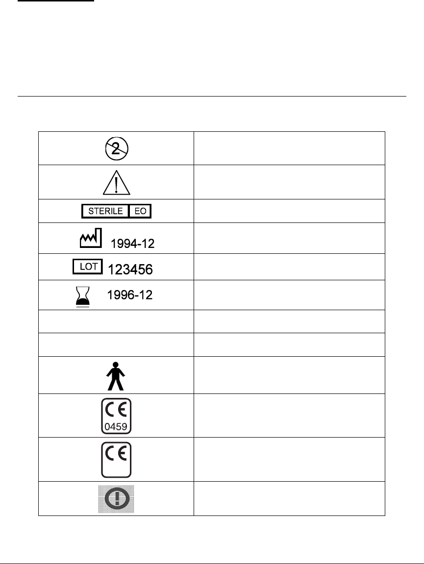
103
APPENDIX A Label information symbol
dictionary
Do Not Reuse This Device
Please Read “Important Information”
Sterilized by Ethylene Oxide
Manufacture Date (Year-Month)
Lot Number
Expiration Date (Use By Date)
(Year-Month)
REF MMT-XXXX Reference / Record Number (reorder number)
SN Device Serial Number
IEC Icon indicating equipment providing a
particular degree of protection against electric
shock (Type B)
CE Marking
CE Marking
Radio Frequency (RF) is not harmonized
0976
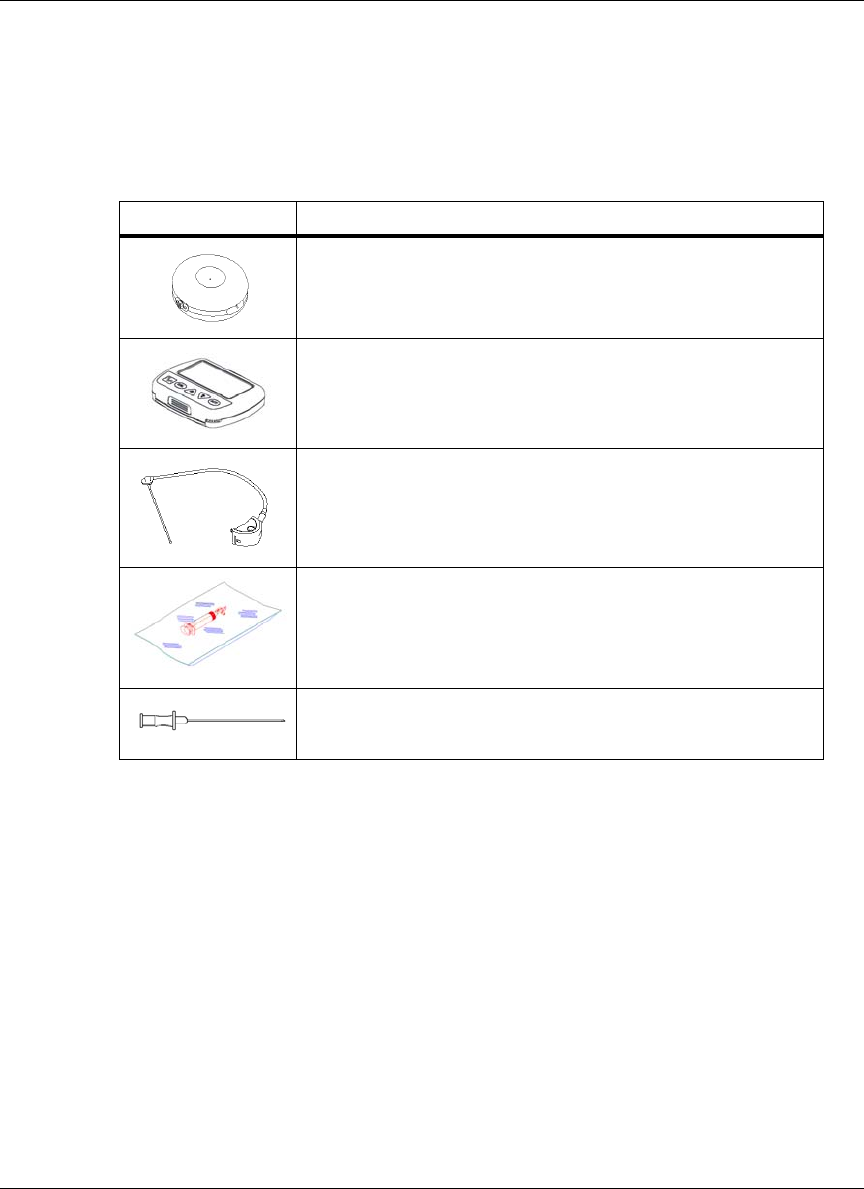
104
Packaging
The icon on each label indicates the contents of the package. The number with
the icon is the quantity. Descriptions of the icons are in the table below.
Other information
Icon Description
Medtronic MiniMed 2007D Implantable Insulin Pump
Medtronic MiniMed 3160 Personal Pump Communicator (PPC)
Medtronic MiniMed Side Port Catheter - MMT 4024 and MMT 4027
Medtronic MiniMed 4105 Refill Kit
Medtronic MiniMed 4102 Refill Needles
Manufactured by: Medtronic MiniMed
Distributed in the United States by: Medtronic MiniMed
Distributed in Europe by: Medtronic EOC, Netherlands
CE Marking:
Notified Body: GMED - France
Notified Body Authorizations: 0459, 0976
Year of Initial CE Authorization: 2000

105
APPENDIX B Implant worksheet
Implant worksheet form
Please refer to “Implant Worksheet” attached.

Medtronic MiniMed Implant Worksheet Form
Prep Date:_________ Center:_________ Patient Code:___
Patient name:_________________________________
Pump Label:
Catheter Label:
PPC Label:
Insulin Lot Number:_________
Communicator-settings:
Patient Communicator ID:________ Supervisor Code:__
Max meal bolus:____ U Max basal rate:_______U/h
Maximums (locked/unlocked):__ Alarm feedback "ON":__
Basal rate programmed with PPC:________U/h
Weight of full "IN 2" syringe before filling the
reservoir:_____________________g (1)
Weight of full "IN 2" syringe after filling the reservoir and
removing 2ml from the pump:__________________ g (2)
Total amount placed in the reservoir
(1-2):_________________ g
Verification of alarm feedback: yes / no
Time delivery started, priming bolus:_____________
Calculated stroke volume:____________________
a) number of strokes delivered:________________
b) total volume delivered:_________________
c) calculated stroke volume (b/a):__________ ul
Verification of the delivery from the catheter tip: yes / no
Implant date:_____________
Surgeon name:________________
Anesthesia:____________________
Pocket depth:_________cm
Catheter fixation:________________
Pump fixation:__________
Catheter type:_______________
Pump type:_______________
Pump orientation:
Complications:

107
APPENDIX C Refill form
Pump refill data
Please refer to “Refill Data Form” attached.
Medtronic MiniMed Refill Worksheet
Before the refill: U/384.6=_________ g (F)*
Insulin remaining from PPC:_____________________ (F)
Data:
Weight of primed "RB" syringe:_____________ g (A)
Weight of "RB" syringe after
insulin withdrawn:______________________ g (B)
Weight of filled "IN" syringe:_____________ g (C)
Weight of "IN" after pump filled and 2ml
withdrawn:______________________________ g (D)
Amount withdrawn Refill Amount
(B)_______________ g (C)_________________ g
(A)_______________ g _ (D)________________ g
= _______________ g (E) = _______________ g (G)
*Corrected for density of insulin
Patient name:___________________
Patient code:________
Center:_____________________
Physician name:____________
Insulin "IN" _______ Rinse Buffer "RB" ________
Previous refill amount:____________________ g (1)
Residual amount withdrawn (E):______________ g (2)
Actual amount used (line 1 - line 2):____________ g (3)
Theoretical amount used:__________________ g (4)
(line 1 - remaining dose from PPC (F)
Difference between actual and theoretical
amount used (line 4 - line 3):___________________ g (5)
Refill accuracy (line 5 / line 4, then x 100):________ %
Usable units of insulin (gx384.6): _______________ U
Average daily insulin use:____________________ U/d
Estimated refill period:___________________ Days
Schedule next refill visit:_______________
D / M / Y

109
APPENDIX D Precautions and general
procedures
Special note and precautions
Before beginning the implant, refill, stroke volume measurement, rinse/flush, or
pressure measurement procedure, carefully read this Appendix and keep the
information in mind as you perform each procedure.
1. All procedures should be performed using ASEPTIC TECHNIQUE.
2. Air in the Pump System has been shown to be a significant contributing
factor to aggregation of insulin. Proper degassing of all solutions that enter
the Pump is essential. Read the insert in the refill kit packaging about the
degassing procedure.
3. When using the refill kit, never release the syringe-locking ring while there is
a vacuum within the refill syringe. The plunger of the syringe will snap back
forcefully and may rupture the syringe and eject the contents.
4. It is important that the syringe needle is perpendicular to the fill port to
prevent binding when entering or exiting.
5. The Side Port Catheter attachment site contains up to 20 units of INSULIN.
The distal portion of the Catheter and the tubing can contain up to 13 units of
INSULIN. However, the INSULIN in the Pump fluid pathway and the side
port receptacle can be cleared by following the procedure to pull RINSE
BUFFER through the side port. During a flush procedure to push out a
catheter tip blockage, the 13 units in the distal catheter will be delivered to
the patient. The 13 units can be managed by programming continuous bolus
amounts prior to the procedure, or with the use of oral or IV glucose as
needed during the procedure. Individual patient response to INSULIN bolus
amounts must be considered.
6. Patient blood glucose monitoring must be performed during, and up to one
hour after the procedure. Oral and intravenous glucose should be available
for glycemic management.

110
7. After the flush procedure, at least 13 units of RINSE BUFFER will remain in
the distal portion of the catheter. Programmed bolus amounts to remove the
RINSE BUFFER may be completed before the patient leaves the clinic. A
prescribed INSULIN basal rate should be programmed when the system is
clear of RINSE BUFFER.
8. Never push down on the plunger to fill the Pump. When the Medtronic
MiniMed refill needle is properly seated in the fill port, the vacuum in the
reservoir will draw the fluid from the syringe.
9. Each step of the procedure will list the syringes and appropriate fluids needed
for that step. It is suggested that the syringes be prepared and labeled prior to
the start of the procedure.
10. The Side Port Catheter is intended to be accessed only during the implant
procedure, the combined rinse/flush procedure, the catheter flush procedure,
and for diagnostic procedures. The catheter is not intended to provide access
to the peritoneum for bolus injections of fluids or for withdrawal of body
fluids.
General procedures
Before beginning any of the procedures, be sure you are familiar with the general
techniques for locating the Pump fill port and the Side Port Catheter, accessing
the Pump inlet, venting the refill syringe, and preparing the syringes.
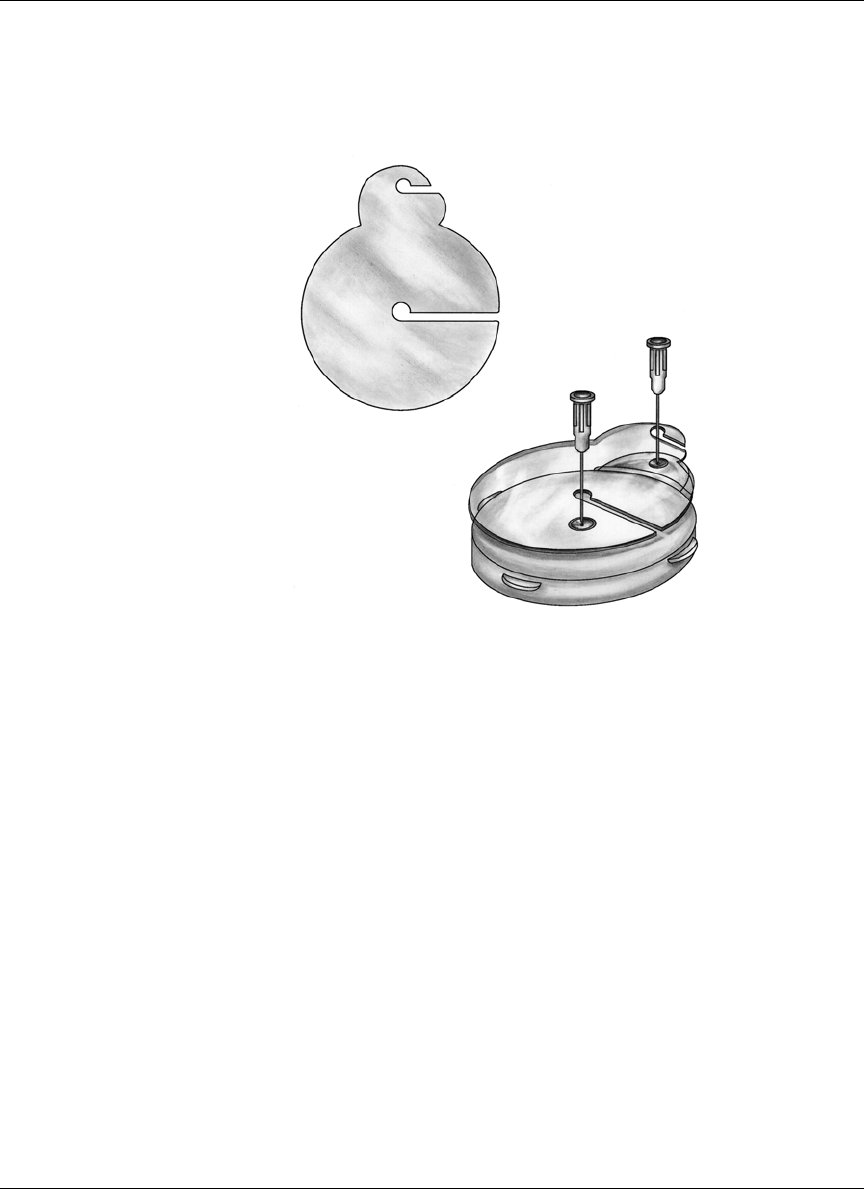
111
Locating the pump fill port and the side port
Figure 15: Template and placement
1. Locate the Pump, then aseptically prep and drape the Pump area. Use topical
or local anesthetic if desired.
2. To locate the Pump fill port, located in the center of the Pump, align the
sterile template (MMT-4106) over the Pump by palpating the Pump
circumference. Then insert an 18 gauge needle into the central Pump fill port
as shown in Figure 15 above.
3. To locate the side port, palpate around the circumference of the Pump. It is
helpful to grasp the side port between the thumb and index finger when
aligning the template.
4. Using the template as a guide, insert the second 18 gauge needle into the side
port as shown. The side port can be accessed by inserting the guide needle
just inside the outer edge of the side port connection. This outer edge is
raised around the outer aspect of the side port, in order to help guide the
needle into the port.
Template
(MMT-4106)
Placement on Skin with
Guide Needles in Position
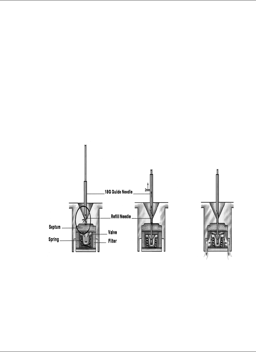
112
Accessing the pump inlet
(See Figure 16.) To enter the Pump fill port or the side port, make sure the refill
syringe stopcock is closed, then pass the Medtronic MiniMed refill needle
(MMT- 4102) through the 18 gauge guide needle. Pull back slightly (approxi-
mately 2 mm) on the guide needle to allow the Medtronic MiniMed refill needle
to enter the Pump fill port or the side port. The refill needle entry opens the inlet
valve of the Pump fill port.
After passing through the septum and seating in the valve, you can feel the
increased force, about 0.5 pounds, required to move the valve 0.5 millimeter to
open. Maintain this downward pressure in the pump fill port to ensure that the
inlet valve remains open. In the case of the side port, a downward pressure is not
required after the needle is completely inserted.
Figure 16: Inlet valve
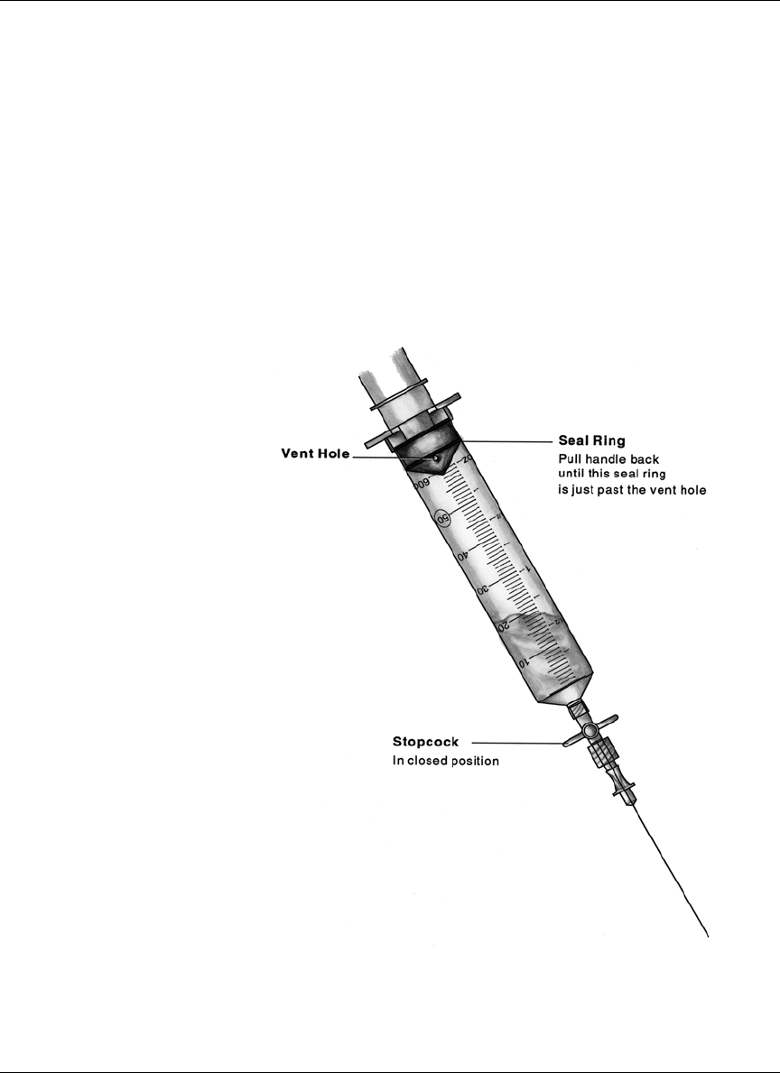
113
Venting the Medtronic MiniMed refill syringe (optional)
In order to fill the Pump, it may be necessary to vent the headspace in the
Medtronic MiniMed refill syringe. Refill syringes do not have lubricant on the
syringe housing or on the plunger tip. Some syringes may be “sticky” and require
the venting procedure described below to assist the vacuum in the Pump to over-
come this condition.
To vent, hold the syringe with the refill needle pointing down. Vent the syringe
headspace by pulling back firmly on the plunger until the second sealing ring on
the rubber cap passes beyond the vent hole as shown in Figure 17.
Figure 17: Venting the refill syringe
NOTE: Be sure that the plunger is retracted far enough
that the vent hole is exposed. The syringe must
be held with the needle facing down and used
within 10 minutes once it is vented. If this time
limit is exceeded, repeat the degassing
procedure and re-vent.

114

115
APPENDIX E Pump rinse procedure
The purpose of this procedure is to dissolve insulin deposits within the Pump res-
ervoir, pumping mechanism, and the Side Port Catheter “port.”
Supplies and solutions
Prior to performing this procedure, assemble the necessary supplies and solutions
as outlined below:
Supplies
• Steri-Strips® and markers
• Local anesthesia (if necessary)
• Sharps container
• Safety glasses
•PPC
• Oral or IV glucose
• Glucose monitoring equipment
•Drapes
• One (1) scale - 0.01 gram resolution
• One (1) sterile bag for PPC (intestinal or cassette bags work well)
• One (1) Side port locating template, MMT-4106
• Seven (7) Refill kits, MMT-4105
• Seven (7) Medtronic MiniMed MMT-4102 refill needles. (Extra needles
should be available to use as needed)
• Eight (8) sharp 18 gauge regular bevel needles

116
Solutions
• 50 ml. sterile 0.1M NaOH (0.4 grams NaOH per 100 ml of Sterile water for
injection) MMT-9005
• Seven (7) 10 ml vials, rinse buffer solution, MMT-2008
• Five (5) 10 ml vials, U-400 Insulin
The 0.1M of NaOH used in this procedure can
cause permanent eye damage. Safety glasses must
be worn during this procedure.
!
WARNING

117
Preparing for the procedure
NOTE: Before beginning any refill, flush, stroke volume
measurement, carefully read Appendix D, Precautions
and General Procedures, and keep this in mind as you
perform each procedure.
In order to prepare for the Side Port Catheter rinse and flush procedure, a total of
seven syringes will need to be labeled and then prepared with different solutions.
Table 1 defines the syringe numbers and corresponding solutions:
Prepare syringes for emptying the Pump
Syringe 1 is used for emptying the Pump. Label and prepare syringe 1 per
Table 1.
Prepare syringes for filling the Pump
During the Catheter rinse/flush procedure, syringes 2, 3, 4, 5, 6, and 7 are used
for filling the Pump. Each of these syringes needs to be labeled with its solution
and syringe number, per Table 1, and then filled and degassed.
Table 1:
Syringe # Syringe type Solution
1Refill 5 ml
RINSE BUFFER
2Refill 20 ml NaOH
3Refill 30 ml NaOH
4Refill 20 ml
RINSE BUFFER
5Refill 30 ml
RINSE BUFFER
6Refill 20 ml INSULIN
7Refill 30 ml INSULIN

118
Program minimal basal rate
Place the PPC in a sterile bag and program the Pump to “SUSPEND” mode, the
basal rate will be 0.2 U/h.
Remove insulin from the Pump and fill with
NaOH
INSULIN is removed from the Pump and then the Pump is filled with NaOH.
The following volumes are used:
• Syringe 1 - 5 ml RINSE BUFFER
• Syringe 2 - 20 ml NaOH
• Syringe 3 - 30 ml NaOH
Follow the steps below to perform this procedure:
Syringe 1: Rinse Buffer - Degassed
1. Prime the needle. Weigh the syringe and record the weight on the refill form
(Line A).
2. Close the stopcock. Obtain a vacuum by pulling back on the plunger until it
locks. Press the lock into the plunger groove to be sure it is firmly secured.
3. Enter the Pump with the refill needle.
4. Open the stopcock; withdraw the INSULIN. After the INSULIN appears to
have stopped rising in the syringe, wait an additional 30 seconds to make
sure all of the INSULIN and air are removed.
NOTE: Air in the Pump System has been shown to be a significant
contributing factor to aggregation of INSULIN. Proper
degassing of all solutions that enter the Pump is
essential.
5. When 30 seconds have elapsed, close the stopcock, remove the syringe.
Weigh the syringe and record the weight on the refill form. Discard the
INSULIN in the syringe except for a 5 ml barrier. This syringe will be used to
pull NaOH through the side port. Attach and prime a new refill needle.

119
The 0.1M NaOH used in this procedure can
cause permanent eye damage. Safety glasses
must be worn during this procedure.
Syringe 2: NaOH - Degassed
1. Prime the needle. Close the stopcock
2. Enter the Pump with the refill needle.
3. Open the stopcock and allow the Pump to fill completely with NaOH. When
the fluid level stops moving, the Pump is filled.
4. Close the stopcock. Remove the syringe.
5. Prepare syringe 2 for aspiration. Remove the air from the syringe. Close
stopcock and obtain a vacuum by pulling back on the plunger until it locks.
Press the lock into the plunger groove to be sure it is firmly secured.
6. Re-enter the Pump.
7. Open the stopcock and remove the NaOH. After the fluid level stops moving,
wait an additional 30 seconds for all the NaOH to be removed.
8. When the time has elapsed, close the stopcock and remove the syringe.
Discard syringe 2.
Syringe 3: NaOH - Degassed
1. Prime the needle. Close the stopcock.
2. Enter the Pump fill port with the refill needle.
3. Open the stopcock and allow the Pump to fill completely with NaOH. When
the Pump is filled, approximately 10 ml will remain in the syringe. Leave this
NaOH in the syringe, and leave this syringe in place for the next step.
!
WARNING

120
Equilibrate and pull NaOH through system
The reservoir pressure in the Pump is equilibrated with outside ambient pressure
and NaOH is pulled through the pumping mechanism. This procedure uses the
following volumes in syringes 3 and 1:
• Syringe 3 with residual NaOH from the previous section.
• Syringe 1 with 5 ml insulin/buffer mixture from previous section.
Syringe 3: NaOH - Residual
1. Verify that the stopcock on syringe 3 is open.
Syringe 1: Insulin - Residual
1. Prime the needle. Close the stopcock.
2. Obtain a vacuum by pulling back on the plunger until it locks. Press the lock
into the plunger groove to be sure it is firmly secured.
3. Enter the side port with the stopcock closed.
4. Open the stopcock.
5. Program and deliver a 4 unit bolus to open the valve in the Pump mechanism.
6. Observe syringe 3. When the level of the NaOH approaches 2 ml, close the
stopcock to prevent air from entering the Pump. Observe syringe 1. At least 1
ml of NaOH must pass into syringe 1 in order to thoroughly clean the Pump
mechanism. If less than 1 ml enters, repeat the bolus from Step 5, some
pumps may require 3 successive boluses to obtain 1 ml.
NOTE: In order to completely dissolve deposits in the Pump
mechanism, it is important to maintain a vacuum with
syringe 1 and deliver the entire bolus.
7. After the bolus, close the stopcock on syringe 1. Remove both syringes. Set
aside syringe 3 for use in removing the NaOH from the Pump fill port in the
next step. Discard syringe 1.

121
Remove NaOH and fill with rinse buffer
The NaOH is removed from the Pump and the system is filled with RINSE
BUFFER. This procedure uses the following volumes in syringes 3, 4, and 5:
• Syringe 3 with residual of at least 5 ml NaOH from previous step
• Syringe 4 with 20 ml RINSE BUFFER
• Syringe 5 with 30 ml RINSE BUFFER
Syringe 3: NaOH - Residual
1. Prepare syringe for aspiration.
2. Close the stopcock and obtain a vacuum by pulling back on the plunger until
it locks. Press the lock into the plunger groove to be sure it is firmly
secured.Enter the Pump with the refill needle.
3. Open the stopcock and withdraw all the NaOH. After the NaOH appears to
have stopped rising in the syringe, wait an additional 30 seconds to make
sure all the NaOH and air is removed.
4. When the time has elapsed, close the stopcock, remove the syringe, and
discard.
Syringe 4: Rinse Buffer - Degassed
1. Prime the needle. Close the stopcock.
2. Enter the Pump with the refill needle and syringe.
3. Open the stopcock and allow the Pump to fill completely with RINSE
BUFFER. When the fluid level stops moving, the Pump is filled.
4. Close the stopcock. Remove the syringe.
5. Prepare syringe 4 for aspiration. Obtain a vacuum by pulling back on the
plunger until it locks. Press the lock into the plunger groove to be sure it is
firmly secured.
6. Re-enter the Pump.
7. Open the stopcock and remove the RINSE BUFFER. After the fluid level
stops moving, wait an additional 30 seconds for all the RINSE BUFFER and
air to be removed.

122
8. When the time has elapsed, close the stopcock and remove the syringe and set
aside.
Syringe 5: Rinse Buffer - Degassed
1. Prime the needle. Close the stopcock.
2. Enter the Pump fill port with the refill needle.
3. Open the stopcock and allow the Pump to fill completely with RINSE
BUFFER. When the fluid level stops moving, the Pump is filled. When the
pump is filled, approximately 10 ml of RINSE BUFFER will remain in the
syringe. Leave the RINSE BUFFER in the syringe and leave the syringe in
place for the next step.
Equilibrate and pull rinse buffer through system
The reservoir pressure in the Pump is equilibrated with outside ambient pressure
and RINSE BUFFER is pulled through the fluid system. This procedure uses the
following volumes in syringes 4 and 5:
• Syringe 4 with RINSE BUFFER. Expel all RINSE BUFFER except 5 ml.
Change refill needle if desired.
• Syringe 5 with residual RINSE BUFFER from previous step.
Syringe 5: Rinse Buffer
1. Verify that the stopcock on syringe 5 is open.
Syringe 4: Rinse Buffer - Residual
1. Prime the needle of syringe 4. Close the stopcock.
2. Obtain a vacuum by pulling back on the plunger until it locks. Press the lock
into the plunger groove to be sure it is firmly secured.
3. Enter the side port with the stopcock closed.
4. Open the stopcock.
5. To open the valve in the Pump mechanism, program and deliver a 4 unit
bolus using the PPC.
6. Observe syringe 4. When at least 1 ml of RINSE BUFFER has entered
syringe 4, close both stopcocks and remove the syringes. If less than 1 ml
enters, repeat the bolus from Step 6. Some Pumps may require 3 successive

123
boluses to obtain 1 ml. Discard syringe 4 and set aside syringe 5 to be used
later to remove RINSE BUFFER.
Remove rinse buffer and fill with insulin
The RINSE BUFFER is removed from the Pump fluid system and the system is
filled with INSULIN. This procedure uses the following volumes in syringes 5,
6, and 7:
• Syringe 5 with residual RINSE BUFFER from the previous steps
• Syringe 6 with 20 ml INSULIN
• Syringe 7 with 30 ml INSULIN
Syringe 5: Rinse Buffer - Residual
1. Prime the needle. Close the stopcock.
2. Obtain a vacuum by pulling back on the plunger until it locks. Press the lock
into the plunger groove to be sure it is firmly secured.
3. Enter the Pump with the refill needle and syringe.
4. Open the stopcock and remove the RINSE BUFFER. After the fluid level
stops moving, wait an additional 30 seconds to make sure all the RINSE
BUFFER and air are removed.
5. When the time has elapsed, close the stopcock, remove the syringe, and
discard.
Syringe 6: Insulin - Degassed
1. Prime the needle. Close the stopcock.
2. Enter the Pump fill port with the refill needle and syringe.
3. Open the stopcock and allow the Pump to fill completely with INSULIN.
When the fluid level stops moving, the Pump is filled.
4. Close the stopcock and remove the syringe.
5. Prepare syringe 6 for aspiration. Prime needle and close stopcock. Obtain a
vacuum by pulling back on the plunger until it locks. Press the lock into the
plunger groove to be sure it is firmly secured.
6. Re-enter the Pump.

124
7. Open the stopcock, remove the INSULIN. After the fluid level stops moving,
wait an additional 30 seconds for all the INSULIN and air to be removed.
8. When the time has elapsed, close the stopcock and remove the syringe.
Discard all but 5 ml of solution. Remove any air, prime needle and close
stopcock. Set aside the syringe.
Syringe 7: Insulin - Degassed
1. Prime the needle on syringe 7. Weigh and record the combined weight of
syringes 6 and 7 on the Refill Form.
2. Close the stopcock. Enter the Pump fill port with the refill needle.
3. Open the stopcock and allow the Pump to fill completely with INSULIN.
When the fluid level stops moving, the pump is filled. When the Pump is
filled, approximately 10 ml of INSULIN will remain in the syringe. Leave
the syringe in place for the next step.

125
Equilibrate and pull insulin through system
The reservoir pressure in the Pump is equilibrated with outside ambient pressure
and INSULIN is pulled through the fluid system. This procedure uses the follow-
ing volumes in syringes 6 and 7:
• Syringe 7 with residual INSULIN from previous step.
• Syringe 6 with 5 ml solution. To perform this procedure with syringes 6 and
7, follow the steps below:
Syringe 7: Insulin - Residual
1. Maintain syringe 7 with approximately 10 ml of residual INSULIN in the
Pump fill port. Verify that the stopcock on syringe 7 is open.
Syringe 6: Insulin - Residual
1. Prime the syringe 6 needle. Close the stopcock.
2. Obtain a vacuum in syringe 6 by pulling back on the plunger until it locks.
Press the lock into the plunger groove to be sure it is firmly secured.
3. Enter the side port with syringe 6 - stopcock closed.
4. Open the stopcock on syringe 6.
5. Using the PPC, program and deliver a 4 unit bolus.
6. Observe syringe 7. If the level of INSULIN approaches 2 ml, close the
stopcock to prevent air from entering the Pump. Observe syringe 6. At least 1
ml of INSULIN must pass into syringe 6 to assure removal of all the RINSE
BUFFER from the side port. If less than 1 ml enters, repeat the bolus from
Step 6, some Pumps may require 3 successive boluses to obtain 1 ml.
7. Close both stopcocks. Remove syringe 7 from the Pump. Set aside the
syringe to be weighed.
8. With the stopcock closed, remove syringe 6 from the side port. Syringe 6 will
have a vacuum from the previous step. Enter the Pump fill port with syringe
6 and open the stopcock to remove 2 ml. This will restore the negative
pressure safety feature of the Pump.
9. Close the stopcock, remove syringe 6 from the Pump, and set it aside to be
weighed.

126
Remove guide needles and record fill amount
At this point, the 18 gauge guide needles should be removed and the refill
amount should be calculated and recorded. Follow the steps below:
1. Remove the 18 gauge guide needles. Apply pressure to the needle insertion
sites.
2. Weigh syringes 6 and 7 and record on the refill form. Subtract the combined
weight from the weights obtained in step 14 of the section, “Remove RINSE
BUFFER and Fill with Insulin.” The result is the new refill amount.
3. Record the extracted and new refill amounts in the PPC.
Program new basal rate
Using the patient’s PPC, cancel the SUSPEND mode, to return to the normal
patient’s basal rate and modify if needed.

127
APPENDIX F Side Port Catheter flush
procedure
When delivery of insulin is impaired due to catheter tip obstruction, the Catheter
may be flushed using 5 - 10 ml of RINSE BUFFER, MMT-2008.
Supplies and solutions
Prior to performing this procedure, assemble the necessary supplies and solutions
as outlined below:
Supplies
• Steri-Strips® and markers
• Local anesthesia
• Sharps container
•PPC
• Oral or IV glucose
• Glucose monitoring equipment
•Drapes
• One (1) scale - 0.01 gram resolution
• One (1) sterile bag for PPC (intestinal or cassette bags work well)
• One (1) Side port locating template, MMT-4106
• Five (5) Refill kits, MMT-4105
• Six (6) Medtronic MiniMed MMT-4102 refill needles. (Extra needles
should be available to use as needed)
• Eight (8) 18 gauge regular bevel needles
• One (1) 10 or 20 ml Luer Lock® syringe
• One (1) stopcock - 2 way

128
Solutions
• Seven (7) 10 ml vials, Rinse Buffer Solution, MMT-2008
• Five (5) 10 ml vials, U-400 Insulin
NOTE: One-handed flush with a 10-20 mL syringe only.
Preparing for the procedure
NOTE: Before beginning any refill, flush, stroke volume
measurement, carefully read Appendix D, Precautions
and General Procedures, and keep this in mind as you
perform each procedure.
In order to prepare for the Side Port Catheter rinse and flush procedure, a total of
five different refill syringes and one 10 or 20 ml syringe will need to be labeled
and prepared with different solutions. Table 2 defines the syringe numbers and
corresponding solutions.
Record patient’s blood glucose
Record the patient’s blood glucose value at the start of the procedure. Monitor
blood glucose every 30 minutes, or as needed.
Table 2: Preparation and labeling of syringes
Syringe # Syringe type Solution
#1 Refill 5 ml
RINSE BUFFER
#2 Refill 20 ml
RINSE BUFFER
#3 Refill 30 ml
RINSE BUFFER
#4 10 ml 5-10 ml
RINSE BUFFER
#5 Refill 20 ml
INSULIN
#6 Refill 30 ml
INSULIN

129
Prepare syringes for emptying the Pump
Syringe 1 is used for emptying the Pump. Prepare syringe 1 as described in the
"Precautions and General Procedures" section in Appendix D of this manual.
Label the syringe per table 2.
After the syringe is prepared, weigh the syringe and enter the weight on the Refill
Form.
Prepare syringes for filling the Pump
During the Catheter flush procedure, syringes 2, 3, 5, and 6 are used for filling
the Pump. Each syringe should be labeled per Table 2, then filled and degassed
following the General Procedures section in Appendix D of this manual.
Prepare syringe for flushing the Side Port Catheter
During the Catheter flush procedure, syringe 4 is used for flushing the Side Port
Catheter. This syringe needs to be labeled and then prepared by following the
steps below:
1. Firmly attach a stopcock to the 10 or 20 ml Luer Lock connector of a 10 or 20
ml syringe. Then attach an 18 gauge needle to the stopcock.
NOTE: Use only a 10-20 ml Luer Lock syringe for this
procedure. Smaller syringes may damage the Catheter
and/or Pump, by allowing too much high pressure.
2. Draw 5-10 mL of RINSE BUFFER into the syringe.
3. Expel all air from the syringe.
4. Close the stopcock and remove the 18 gauge needle from the syringe.
5. Fill the hub of the Medtronic MiniMed refill needle with RINSE BUFFER
from the syringe and attach it to the syringe.
6. Prime the Medtronic MiniMed refill needle completely.
7. Close the stopcock.
8. Set the syringe aside.

130
Flushing the Side Port Catheter
Program minimal basal rate
Place the PPC in a sterile bag and program the pump to “SUSPEND” mode, the
basal rate will be 0.2 U/h.
Remove insulin and fill with rinse buffer
The INSULIN is removed from the Pump and the system is filled with RINSE
BUFFER. This procedure uses the following volumes in syringes 1, 2, and 3:
• Syringe 1 with 5 ml RINSE BUFFER
• Syringe 2 with 20 ml RINSE BUFFER
• Syringe 3 with 30 ml RINSE BUFFER
Syringe 1: Rinse Buffer
1. Prime the needle and close the stopcock. Weigh the syringe.
2. Obtain a vacuum by pulling back on the plunger until it locks. Press the lock
into the plunger groove and be sure it is firmly secured.
3. Enter the Pump with the refill needle.
4. Open the stopcock and withdraw the INSULIN. After the INSULIN appears
to have stopped rising in the syringe, wait an additional 30 seconds to make
sure all of the INSULIN and air are removed.
NOTE: Air in the Pump System has been shown to be a
significant agonist to aggregation of INSULIN. Proper
degassing of all solutions that enter the Pump is
essential.
5. When the time has elapsed, close the stopcock, remove the syringe. Weigh
the syringe and record the weight on the Refill Worksheet.
Syringe 2: Rinse Buffer - Degassed
1. Prime the needle and close the stopcock.
2. Enter the Pump with the refill needle.

131
3. Open the stopcock and allow the Pump to fill completely with RINSE
BUFFER. When the fluid level stops moving, the Pump is filled.
4. Close the stopcock and remove the syringe.
5. Prepare syringe 2 for aspiration. Obtain a vacuum by pulling back on the
plunger until it locks. Press the lock into the plunger groove and be sure it is
firmly secured.
6. Re-enter the Pump.
7. Open the stopcock and remove the RINSE BUFFER. After the fluid level
stops moving, wait an additional 30 seconds for all the RINSE BUFFER and
air to be removed.
8. When the time has elapsed, close the stopcock and remove the syringe.
9. Prime the needle and close the stopcock.
Syringe 3: Rinse Buffer - Degassed
1. Enter the Pump fill port with the refill needle.
2. Open the stopcock and allow the Pump to fill completely with RINSE
BUFFER. When the fluid level stops moving, the Pump is filled. When the
Pump is filled, approximately 10 mL of RINSE BUFFER will remain in the
syringe. Leave the RINSE BUFFER in the syringe, and leave the syringe in
place for the next step.
Equilibrate and pull rinse buffer through system
The reservoir pressure in the Pump is equilibrated with ambient pressure and
RINSE BUFFER is pulled through the fluid system. This procedure uses syringes
2 and 3:
• Syringe 2 with RINSE BUFFER. Expel all RINSE BUFFER except 5 mL.
Change the refill needle if desired.
• Syringe 3 with residual RINSE BUFFER from the previous section.
Syringe 3: Rinse Buffer - Residual
1. Maintain syringe 3 with approximately 10 mL of RINSE BUFFER in the
Pump fill port. Verify that the stopcock on syringe 3 is open.
Syringe 2: Rinse Buffer - Residual

132
1. Prime the needle. Close the stopcock.
2. Obtain a vacuum by pulling back on the plunger until it locks. Press the lock
into the plunger groove to be sure it is firmly secured.
3. Enter the side port with the stopcock closed.
4. Open the stopcock.
5. Program and deliver a 4 unit bolus to open the valve in the Pump mechanism.
6. Observe syringe 3. When the level of the RINSE BUFFER approaches 2 mL,
close the stopcock to prevent air from entering the Pump. Observe syringe 2.
When at least 1 mL of RINSE BUFFER has entered syringe 2 close both
stopcocks and remove the syringes. If less than 1 ml enters, repeat the bolus
from Step 6. Some Pumps may require 3 successive boluses to obtain 1 ml.
Discard syringe 2 and set aside syringe 3 to be used later to remove the
RINSE BUFFER.
Flush side port catheter
The Side Port Catheter is flushed using syringe 4 which is completely filled with
RINSE BUFFER.
Approximately 13 units of INSULIN remain in the
distal Side Port Catheter. This INSULIN will be
delivered to the patient rapidly in the next three
steps. Alternatively, the INSULIN may be removed
prior to flushing by programming continuous
bolus amounts. Closely monitor blood glucose dur-
ing INSULIN delivery, and administer intravenous
glucose or glucogen as needed.
Syringe 4: Rinse Buffer
1. Prime the needle. Close the stopcock.
2. Enter the side port with the needle.
3. When the needle is firmly positioned in the side port, open the stopcock and
quickly push the plunger all the way down. This should take no longer than
one to two minutes.
4. After flushing, close the stopcock, remove and discard the syringe.
!
WARNING

133
NOTE: This is the only time a plunger should be manually
pushed down.
Remove rinse buffer and fill with insulin
The RINSE BUFFER is removed from the Pump fluid system and the system is
filled with insulin. This procedure uses the following volumes in syringes 3, 5,
and 6:
• Syringe 3 with residual RINSE BUFFER from the previous step
• Syringe 5 with 20 ml INSULIN
• Syringe 6 with 30 ml INSULIN
Syringe 3: Rinse Buffer - Residual
1. Prime the needle. Close the stopcock.
2. Obtain a vacuum by pulling back on the plunger until it locks. Press the lock
into the plunger groove and be sure it is firmly secured.
3. Enter the Pump with the refill needle and syringe.
4. Open the stopcock and remove the rinse buffer. After the fluid level stops
moving, wait an additional 30 seconds to make sure all of the RINSE
BUFFER and air is removed.
5. When the time has elapsed, close the stopcock, remove the syringe, and
discard it.
Syringe 5: Insulin - Degassed
1. Prime the needle and close the stopcock.
2. Enter the Pump fill port with the refill needle.
3. Open the stopcock and allow the Pump to fill completely with INSULIN.
When the fluid level stops moving, the Pump is filled.
4. Close the stopcock and remove the syringe.
5. Prepare syringe 6 for aspiration. Obtain a vacuum by pulling back on the
plunger until it locks. Press the lock into the plunger groove to be sure it is
firmly secured.
6. Re-enter the Pump.

134
7. Open the stopcock and remove the INSULIN. After the fluid level stops
moving, wait an additional 30 seconds for all INSULIN and air to be
removed.
8. When the time has elapsed, close the stopcock and remove the syringe.
Discard all but 5 mL of the solution. Remove the air and set aside the
syringe.
Syringe 6: Insulin - Degassed
1. Weigh and record the combined weight of syringes 5 and 6 on the Refill
Worksheet. Prime the needles.
2. Close the stopcocks. Enter the Pump fill port with the refill needle.
3. Open the stopcock and allow the Pump to fill completely with INSULIN.
When the fluid level stops moving, the Pump is filled. Approximately 10 mL
of INSULIN will remain in the syringe. Leave the syringe in place for the
next step.
Equilibrate and pull insulin through system
The reservoir pressure in the Pump is equilibrated with outside ambient pressure
and INSULIN is pulled through the fluid system. This procedure uses the follow-
ing volumes in syringes 5 and 6:
• Syringe 6 with residual INSULIN from the previous step
• Syringe 5 with 5 mL solution of Rinse Buffer.
Syringe 6: Insulin - Residual
1. Maintain syringe 6 with approximately 10 mL of residual insulin in the Pump
fill port. Verify that the stopcock on syringe 6 is open.
Syringe 5: Rinse Buffer -Residual
1. Prime the syringe 5 needle and close the stopcock.
2. Obtain a vacuum in syringe 5 by pulling back on the plunger until it locks.
Press the lock into the plunger groove and be sure it is firmly secured.
3. Enter the side port with syringe 5 - stopcock closed.
4. Open the stopcock on syringe 5.

135
5. Press SEL. When the PPC screen is flashing “PUMP SUSPEND” press
ACT. The system is now in normal mode.
6. Using the PPC, program and deliver a 4 unit bolus.
7. Observe syringe 6. If the level of INSULIN approaches 2 mL, close the
stopcock to prevent air from entering the Pump. Observe syringe 5. At least 1
mL of INSULIN must pass into syringe 5 to be sure that all of the RINSE
BUFFER is removed from the side port. If less than 1 ml enters, repeat the
bolus from Step 7, some Pumps may require 3 successive boluses to obtain 1
ml.
8. Close both stopcocks. Remove syringe 6 from the Pump. Set the syringe
aside to be weighed.
9. With the stopcock closed, remove syringe 5 from the side port. It will have a
vacuum inside from the previous step. Enter the Pump fill port with syringe 5
and open the stopcock and remove 2 ml. This will restore the negative
pressure safety feature of the Pump.
10. Close the stopcock, remove syringe 5 from the Pump, and set it aside to be
weighed.
11. Press SEL until the “SUSPEND PUMP” screen is displayed. Then Press
ACT.
Remove guide needles and record refill amount
At this point, the 18 gauge guide needles should be removed, and the refill
amount should be calculated and recorded.
1. Remove the 18 gauge guide needles and discard them. Apply pressure to the
insertion sites.
2. Weigh syringes 5 and 6 and record the combined weight on the Refill Form.
Subtract the combined weight from the weight obtained in step 14. Remove
Rinse Buffer and Fill with Insulin. The result is the new refill amount.
3. Record the new and extracted refill amount in the PPC refill worksheet.
Program new basal rate
Using the patient’s PPC, cancel the “SUSPEND” mode and allow the Pump to
return to the patient’s original basal rate.

136
Remove rinse buffer from catheter
Approximately 13 units of RINSE BUFFER remain in the distal Side Port Cathe-
ter. Depending on blood glucose values, program the appropriate bolus amount to
remove the RINSE BUFFER from the Catheter. Release the patient when blood
glucose levels are stable.

137
APPENDIX G Stroke volume
measurement
If under-delivery of insulin is noted during a refill procedure or suspected due to
blood glucose control, it may be useful to verify the proper stroke volume of the
Pump by accessing the side port.
In this procedure, a pipette is attached to a stopcock and refill needle. This system
is inserted into the side port. The insulin pulses in the pipette are measured to cal-
culate the pump stroke volume.
Supplies and solutions
Prior to performing this procedure, assemble the necessary supplies and solutions
as outlined below:
Supplies
• Local anesthesia
• Sharps container
•PPC
• Oral or IV glucose
• Glucose monitoring equipment
•Drapes
• 5 ml or 3 ml syringe
• One (1) sterile bag for PPC (intestinal or cassette bags work well)
• One (1) Side port locating template, MMT-4106
• One (1) sterile 100 microliter pipette, MMT-4104
• Two (2) 18 gauge needles
• One (1) MiniMed MMT-4102 refill needle. (Extra needles should be
available to use as needed)
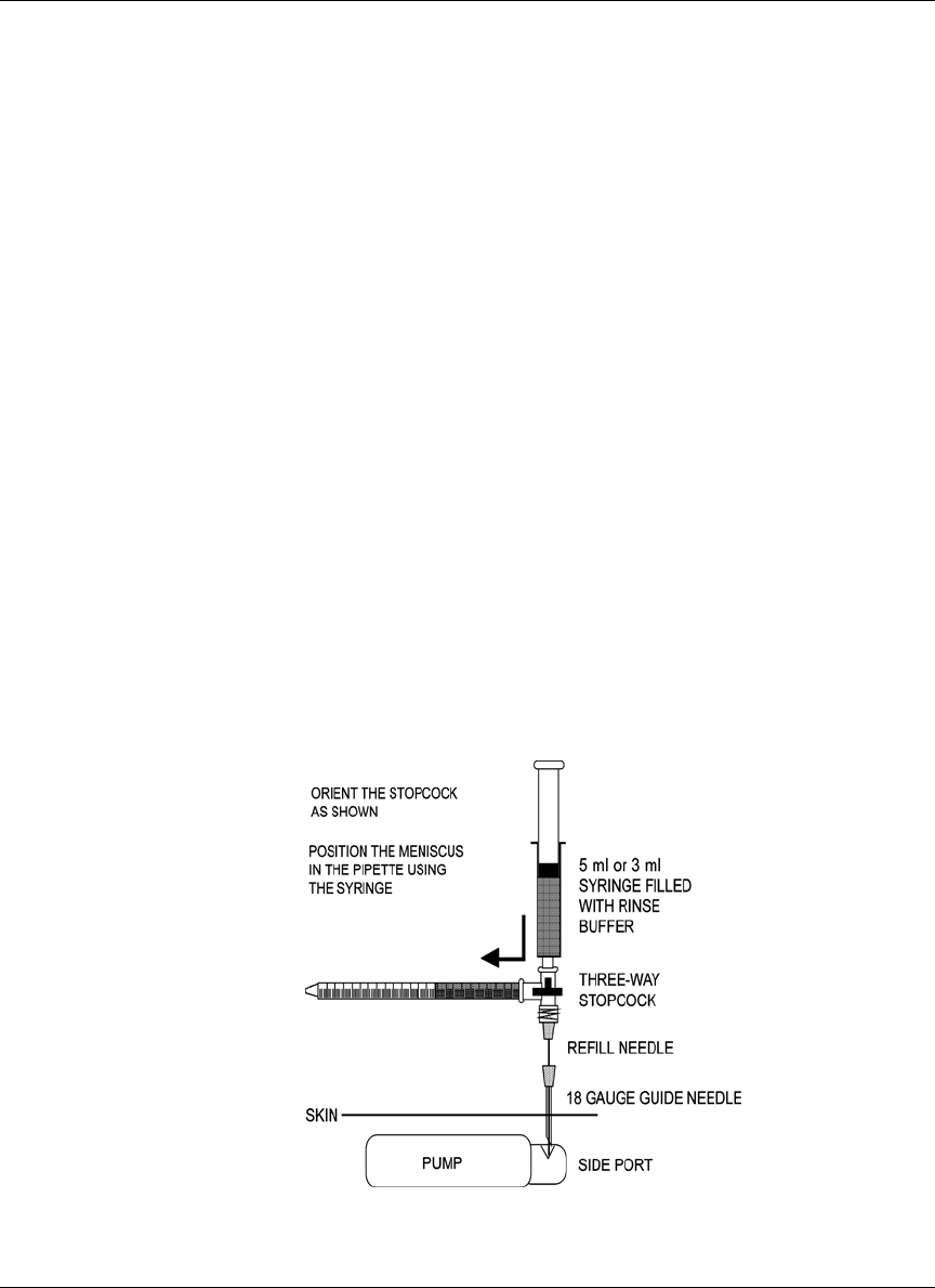
138
• One (1) sterile stopcock - 3 way
Solutions
• One (1) 10 mL vial, Rinse Buffer Solution, MMT-2008
Preparing for the procedure
NOTE: Before beginning any refill, flush, stroke volume
measurement, carefully read Appendix D, Precautions
and General Procedures, and keep this in mind as you
perform each procedure.
Record patient’s blood glucose
Record the patient’s blood glucose value at the start of the procedure. Monitor
blood glucose every 30 minutes, or as needed.
Measuring stroke volume
1. In a sterile field before the procedure; prepare the apparatus. Prime the
stopcock, pipette, and needle.
2. Turn the stopcock as shown in Figure 18. Press on the syringe to obtain a
liquid meniscus in the pipette.
Figure 18: Stroke volume measurement setup
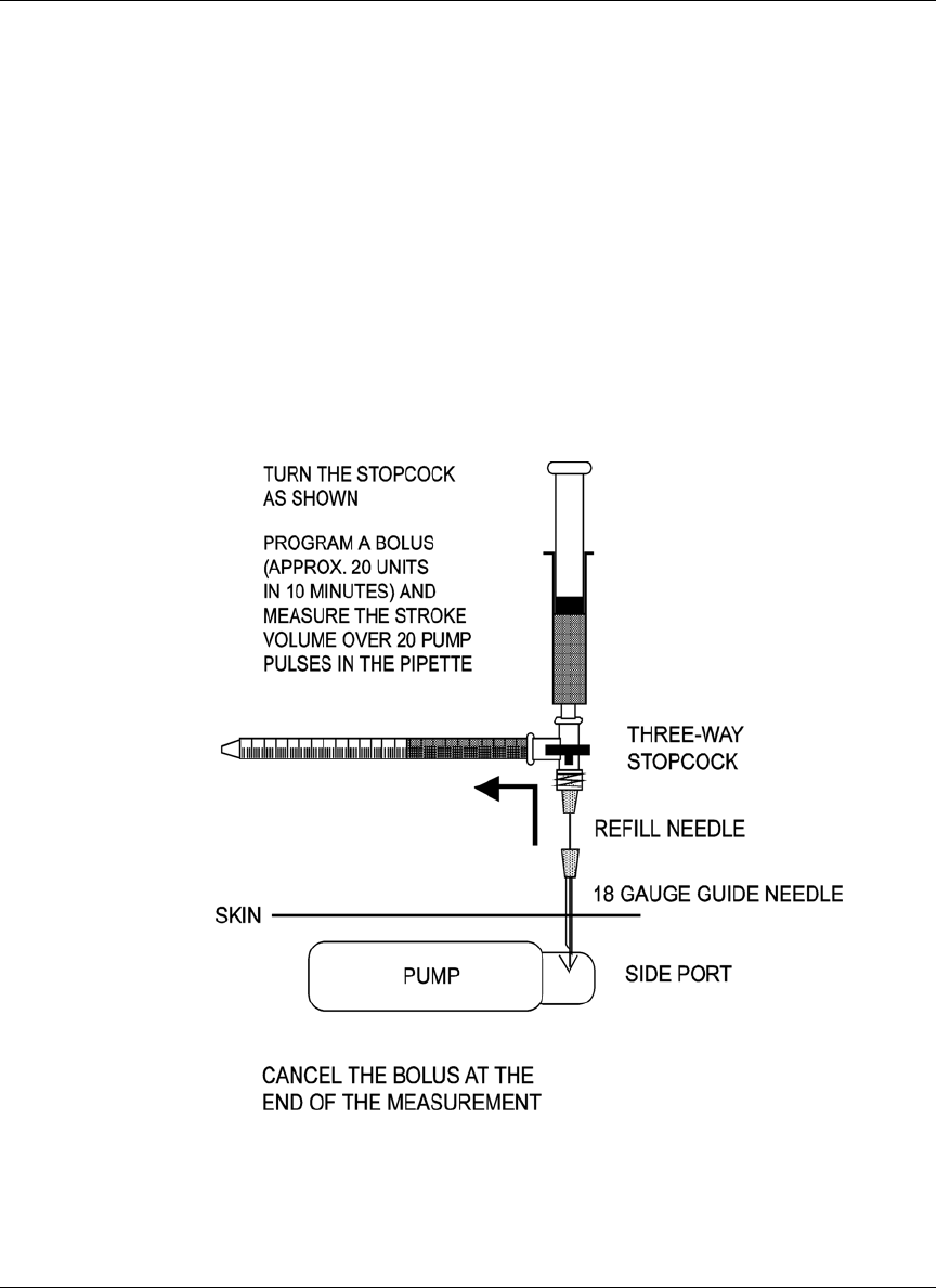
139
3. Insert the needle into the side port.
4. Turn the stopcock as shown in Figure 19.
5. Program a high rate bolus (approximately 20 units) and measure the stroke
volume over 20 pulses in the pipette.
6. Cancel the bolus at the end of the measurement.
7. Turn the stopcock back to the position shown in Figure 19 to close. Remove
the apparatus.
Figure 19: Stroke volume measurement

140
Record patient’s blood glucose
It is likely that some insulin is pumped out of the Catheter and into the patient in
this procedure. Monitor the patient’s blood glucose and release the patient only
after blood glucose values are stable.