Mercury Networks QUANTUM6636 6x6 MIMO WiMAX Base Station User Manual Quantum 2200 Installation Guide v2 1
Mercury Networks, LLC 6x6 MIMO WiMAX Base Station Quantum 2200 Installation Guide v2 1
Contents
Updated user guide RevC

Quantum 2200
High performance, all outdoor
Mobile WiMAX base stations
PureWave Quantum 2200
Installation Guide v2.1
ING-00702-001 Rev C

Quantum 2200 Installation Guide v2.1
Page 2
© PureWave™ Networks 2011. All rights reserved. PureWave™ Networks has prepared this manual for
use by PureWave Networks personnel, licensees, customers, and customers of customers. The
information contained herein is the property of PureWave Networks and shall neither be reproduced in
whole nor in art without prior written approval from PureWave Networks.
PureWave Networks reserves the right to make changes without notice to the specifications and
materials contained herein, and shall not be responsible for any damages caused by reliance on the
material presented, including, but not limited to, typographical, arithmetic and listing errors.

Quantum 2200 Installation Guide v2.1
Page 3
Contents
Contents ........................................................................................................................................................ 3
Figures ........................................................................................................................................................... 5
Tables ............................................................................................................................................................ 6
Regulatory Notice ......................................................................................................................................... 7
Safety Precautions ........................................................................................................................................ 8
1 Preface .................................................................................................................................................. 9
1.1 About This Document ................................................................................................................... 9
1.2 Symbols used in this Document .................................................................................................... 9
1.3 Packaging and Components .......................................................................................................... 9
1.4 Locating the Product Serial Number ........................................................................................... 10
1.5 Obtaining Documentation and Support ...................................................................................... 10
2 Base Station Basics .............................................................................................................................. 11
2.1 Physical and Environmental Specifications ................................................................................. 11
2.2 Physical and Environmental Specifications ................................................................................. 12
2.3 Connectors and Indicators .......................................................................................................... 13
3 Mounting the Base Station ................................................................................................................. 15
3.1 Fundamentals ............................................................................................................................. 15
3.2 The Pole-Mount Kit ..................................................................................................................... 16
3.2.1 Pole Mount Installation Procedure ..................................................................................... 17
4 Mounting the Antennas ...................................................................................................................... 21
5 Connecting the Antennas to the Base Station .................................................................................... 22
5.1 Installation of Lightning Surge Protectors .................................................................................. 22
5.2 Connecting the Antennas to the Base Station ............................................................................ 24
6 Installing the GPS Antenna.................................................................................................................. 25
6.1 Selecting and Mounting a GPS Antenna ..................................................................................... 25
6.2 Connecting the GPS Antenna to the Base Station ...................................................................... 26
7 Connecting Ethernet and Serial Console Cables ................................................................................. 27
7.1 The PureWave Basic DC Installation Kit ...................................................................................... 27

Quantum 2200 Installation Guide v2.1
Page 4
7.2 Preparing the Ethernet and Console Cables ............................................................................... 28
7.3 Weatherproofing the Ethernet and Console Connections ......................................................... 29
8 Connecting DC Power and Ground ..................................................................................................... 31
8.1 Base Station Single-Point Grounding .......................................................................................... 31
8.2 Preparing the DC Power Connector ............................................................................................ 31
Appendix A Connector Weatherproofing ............................................................................................... 38
Required Materials ................................................................................................................................. 38
General Guidelines for Working with Weatherproofing Tape ................................................................ 38
Weatherproofing Procedures ................................................................................................................. 39
Appendix B Warranty Statements .......................................................................................................... 42
Hardware ................................................................................................................................................ 42
Software .................................................................................................................................................. 42
Additional Conditions.............................................................................................................................. 43
No Fault Found ........................................................................................................................................ 43
Warranty Limitations .............................................................................................................................. 43
Warranty Disclaimer ............................................................................................................................... 43
Obtaining Warranty Service .................................................................................................................... 44
Out of Box Failure (OBF) / Dead on Arrival (DOA) .................................................................................. 45
Advanced Replacement .......................................................................................................................... 45
Assistance................................................................................................................................................ 46

Quantum 2200 Installation Guide v2.1
Page 5
Figures
Figure 1: PureWave Quantum 2200 Base Station .............................................................................. 11
Figure 2 Mounted PureWave Quantum 2200 .................................................................................... 11
Figure 3: Base Station Connectors ..................................................................................................... 13
Figure 4: Base Station Mounting Holes ............................................................................................. 15
Figure 5: Example of Mounting Point with Spacing Hardware ............................................................ 15
Figure 6: Example Deployment Consisting of Pole Attached to a Metal Frame ................................... 16
Figure 7: Base Station Pole Mount Assembly Diagram ....................................................................... 18
Figure 8: Base Station Mounting Bracket .......................................................................................... 18
Figure 9: Pole Mounting Plates ......................................................................................................... 19
Figure 10: Base Station Mounting Bracket Alignment ........................................................................ 19
Figure 11: Pole Mount Subassembly ................................................................................................. 20
Figure 12: Pole-Mounted PureWave Antenna ................................................................................... 21
Figure 13 Antenna Connection ......................................................................................................... 24
Figure 14: Optional GPS Antenna and Mounting Kit .......................................................................... 25
Figure 15: T-567B RJ-45 Connector .................................................................................................... 29
Figure 16: RJ-45 IP67 Weatherproof Housing Assembly ..................................................................... 29
Figure 17: Assembled RJ-45 IP67 Weatherproof Housing ................................................................... 30
Figure 18: IP67 DC Power Connector and Pin Assignments ................................................................ 32
Figure 19: Crimp and Insertion Tools for the DC Power Connector ..................................................... 32
Figure 20: Slide connector onto cable before crimping. ..................................................................... 33
Figure 21: Wire properly inserted into circular socket crimp contact .................................................. 33
Figure 22: Side and top views of correct crimping technique ............................................................. 34
Figure 23: Properly completed first crimp ......................................................................................... 34
Figure 24: Start the second crimp with tool section “A”. .................................................................... 35
Figure 25: Complete the second crimp with tool section “B”. ............................................................ 35
Figure 26: Fully completed pin .......................................................................................................... 35
Figure 27: Pins inserted into DC power connector ............................................................................. 36
Figure 28: Use needle-nose pliers to push the pins further into the plug. ........................................... 36
Figure 29: Use insertion tool to secure the pins in the plug. ............................................................... 37
Figure 30: Front view of plug with crimp pins properly inserted......................................................... 37
Figure 31: Completed Power Connector Assembly ............................................................................ 37
Figure 32: Proper Weatherproof Tape Overlap .................................................................................. 38
Figure 33: Torque Wrench for N-Type Connector .............................................................................. 39
Figure 34: First Plastic Tape Layer ..................................................................................................... 39
Figure 35: First Rubber Tape Layer .................................................................................................... 40
Figure 36: Wrapping Plastic Tape on Top of the Rubber Tape ............................................................ 40
Figure 37: Wrapping ¾”Plastic Tape 1” Below Previous Wrap ............................................................ 41

Quantum 2200 Installation Guide v2.1
Page 6
Tables
Table 1: Quantum Environmental and Mechanical Specifications ...................................................... 12
Table 2: Base Station LED Description ............................................................................................... 13
Table 3: Base Station Connector Descriptions ................................................................................... 14
Table 4: PureWave Quantum Base Station Pole Mount Kit Contents .................................................. 17
Table 5: PureWave Quantum Surge Protection Kit Contents .............................................................. 22
Table 6: PureWave Quantum Surge Protection Kit Specifications....................................................... 23
Table 7: PureWave Quantum Basic DC Installation Kit Contents ........................................................ 27
Table 8: Cat 5e+ Connector Pinout .................................................................................................... 28
Table 9: Summary of PureWave RMA Conditions and Charges ........................................................... 45
Quantum 2200 Installation Guide v2.1
Page 7
Regulatory Notice
This device complies with the FCC limits a class B digital device, pursuant to Part 15 of the FCC Rules. A
complete list of regulatory certifications can be provided by PureWave upon request. These limits are
designed to provide reasonable protection against harmful interference in a residential installation. This
equipment generates, uses, and can radiate radio frequency energy and, if not installed and used in
accordance with the instructions, may cause harmful interference to radio communications. However,
there is no guarantee that interference will not occur in a particular installation. If this equipment does
cause harmful interference to radio or television reception, which can be determined by turning the
equipment off and on, the user is encouraged to try to correct the interference by one or more of the
following measures:
• Re-orient or relocate the receiving antenna/s.
• Increase the separation between the equipment and other receiver.
• Connect the equipment into an outlet on a circuit different from that to which the
receiver is connected.
• Consult the dealer or an experienced radio/TV technician for help.
Shielded cables and I/O cords must be used for this equipment to comply with the relevant FCC
regulations.
Changes or modifications not expressly approved in writing by PureWave Networks may void the user's
authority to operate this equipment.
Note: This device must be professionally installed, and the operator and/or the licensed
spectrum holder has the responsibility to comply with FCC regulations.
Note: The contention protocol MUST be turned on and used for the specified band (3.65GHz
- 3.7 GHz) in the specified country or wherever FCC rules and regulations are enforced.
Failure to comply makes the operation of this device illegal.

Quantum 2200 Installation Guide v2.1
Page 8
Safety Precautions
When installing this equipment, please observe the following precautions to minimize the risk of danger
or personnel injury:
NEVER install equipment if there is a chance of lightning or other adverse weather
conditions.
NEVER install equipment in a wet location unless the equipment is specifically design for wet
locations.
NEVER touch un-insultated wires or terminals unless the wire has been disconnected from
any equipment.
ALWAYS use caution when installing or modifying cables.
ALWAYS disconnect all lines and power connections before servicing or disassembling this
equipment.
ALWAYS assume that all components and assemblies are static sensitive and always follow
local ESD-prevention guidelines to prevent equipment damage.
For any external power supply that provides the power source for the PureWave equipment,
replace any power supply fuse with the same rating or equivalent; otherwise PureWave
Networks cannot not be responsible for any subsequent damage to the equipment.
For performance and safety reasons, only power supplies listed for use with telephone
equipment by a Nationally Recognized Testing Laboratory (NRTL) should be used with
equipment.
ALL wiring external to the product(s) should follow the provisions of the current edition of
the National Electrical Code.
These units contain no user serviceable components. Only authorized service personnel
should service or repair these units. Use only isolated Class 2 Power Source, Rated 48V dc
5.0A Minimum.
Quantum 2200 Installation Guide v2.1
Page 9
1 Preface
1.1 About This Document
This guide is intended for use by a professional installer who performs the physical installation of any
PureWave Quantum 2200 Base Station. It does not cover base station functional setup or operation.
For detailed information about setup and operation of the PureWave Quantum 2200 Base Station,
please refer to the Quantum 2200 User’s Guide.
Always refer to the current set of Release Notes for the most up to date information and a description of
the current features as they relate to the PureWave system. These may be different from the
information contained within this “Installation Guide”.
1.2 Symbols used in this Document
Notes, cautions, and timesavers use these conventions and symbols:
Tip
Means the following will help you solve a problem. The tips information might
not be troubleshooting or even an action, but could be useful information.
Note
Means reader take note. Notes contain helpful suggestions or references to
materials not contained in this manual.
Caution
Means reader be careful. In this situation, you might do something that could
result equipment damage or loss of data.
Warning
This warning symbol means danger. You are in a situation that could cause
bodily injury. Before you work on any equipment, be aware of the hazards
involved with electrical circuitry and be familiar with standard practices for
preventing accidents.
1.3 Packaging and Components
Your PureWave Quantum Base Station and accompanying installation kits and hardware have been
packaged into a single box. Some such kits are optional and, if not present, are replaced with empty
boxes to ensure safe and secure shipping. All are listed below:
PureWave Quantum Base Station
PureWave Quantum Basic DC Installation Kit
PureWave Quantum Pole Mounting Kit
PureWave Quantum Surge Protection Kit
GPS Antenna Kit

Quantum 2200 Installation Guide v2.1
Page 10
If you have purchased a 6-Port Antenna Panel or other antenna(s) from PureWave then it is packaged in
a separate box along with its mounting kit and instructions. Please refer to the instructions provided
with your antenna(s) for proper mounting procedures. Connection of the antennas to the base station
is covered within this guide.
1.4 Locating the Product Serial Number
The product identification information, serial number, and certification information are located on a
label on the side panel of the base station. Please take note of and keep this information for your
records, as it is very important for warranty and support services.
1.5 Obtaining Documentation and Support
All requests for documentation and/or support should be addressed to
Technical Support Department
PureWave Networks, Inc.
2660-C Marine Way
Mountain View, CA 94043
E-mail: support@pwnets.com
Tel: 650-528-5200
Fax: 650-528-5222
Quantum 2200 Installation Guide v2.1
Page 11
2 Base Station Basics
2.1 Physical and Environmental Specifications
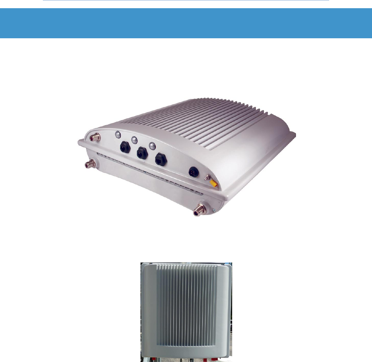
The PureWave Quantum 2200 Base Station (Figure 1) is made up of a single, weather-resistant enclosure
with overall dimensions 17.5” x 16.7” x 5.3” (44cm x 42cm x 13cm). The base station is a single self-
contained unit and has no user-serviceable components.
Figure 1: PureWave Quantum 2200 Base Station
The PureWave Quantum Base Station can be installed indoors or outdoors (Figure 2), however the
antennas must always be installed outdoors.
Figure 2 Mounted PureWave Quantum 2200

Quantum 2200 Installation Guide v2.1
Page 12
2.2 Physical and Environmental Specifications
Table 1 lists the mechanical, electrical, and environmental properties of the PureWave Quantum Base
Station.
Physical & Environmental
Specifications
Dimensions
17.5” x 16.7” x 5.3”
(44cm x 42cm x 13cm)
Weight
32lbs (14.5kg) (does not include mounting hardware)
Power
-48 VDC
90 Watts Max
Temperature
-40C to +55C (ETSI EN 300 019-1.4 Class 4.1E)
Note: An available solar shield is required for ambient
temperatures exceeding +45C with full sun exposure.
Humidity
5-100% non-condensing
Altitude
To 10,000 ft above sea level
Surge Protection
UL497B
Lightning Protection
Min 10kA IEC 6100-4-5 (optional via external kit)
Weatherproofing
IEC IP67
Wind Loading
160Km/hr operation, 200Km/hr survival
Safety and IEC IP
EN 300 019-2-2, GR487, IEC 60529
Vibration and Dust
ETSI EN 300 019-1-4 Class 4.1E
Table 1: Quantum Environmental and Mechanical Specifications
Quantum 2200 Installation Guide v2.1
Page 13
2.3 Connectors and Indicators
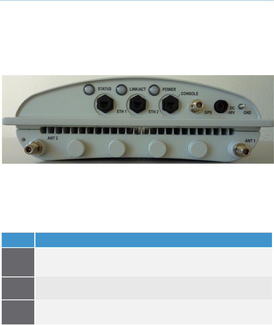
Figure 3 shows the bottom panel of the base station, where all the connectors and indicators are
located.
Figure 3: Base Station Connectors
The base station connector panel contains 3 high-intensity LEDs that are intended to be viewable from
the ground for quick confirmation of the operational state of the base station. Table 2 describes the
function of each LED.
LED
Function
STATUS
Green - BS is up and running normally. No faults detected.
Blinking Red – System booting up, or system is temporarily down.
Solid Red - Fault detected.
Off – LEDs disabled or Power is off. Fault detected if POWER LED is Green, but STATUS LED is Off.
LINK
Solid Green – Connected to an Ethernet switch.
Blinking Green – Ethernet packet activity.
Off – LEDs disabled or no Ethernet activity detected.
POWER
Green – Power is being supplied to the BS.
Off – LEDs disabled or no power is being supplied to the BS.
Table 2: Base Station LED Description
The function of each base station connector/port is described in Table 3. Note that every present
connector must be terminated according to the instructions in this guide to ensure proper base station
operation.

Quantum 2200 Installation Guide v2.1
Page 14
Table 3: Base Station Connector Descriptions
Connector
Function
POWER
-48VDC power source inputs for the unit.
DC power connector: Fits Tyco P/N 796095-2 connector.
GND
This M5 screw provides a ground connection point to the base station. It is the installer’s
responsibility to ensure that the unit is professionally grounded and complies with all relevant
local codes.
GPS
N-type connector for mandatory external GPS antenna. 3.3V power on center pin.
ETH-1
This Gigabit Ethernet port serves as the data traffic backhaul Interface and also provides for in-
band management of the base station. Note that this port may be physically routed directly to
the operator’s network equipment, or it may be daisy-chained through additional PureWave
Quantum sectors by routing it to another unit’s ETH-2 port.
Cat-5 (RJ-45), Single-Mode Fiber (HartingPull/Han 3 A), and Multi-Mode (LC duplex) Fiber
options are available for the ETH-1 port.
ETH-2
This Gigabit Ethernet port serves as an incoming daisy-chain port from a neighboring sector,
and may be used for out-of-band management of the base station. It may also be used to
connect to an external device, such as a web camera. Daisy-chained traffic is aggregated and
passed through the ETH-1 port.
Cat-5 (RJ-45), Single-Mode Fiber (HartingPull/Han 3 A), and Multi-Mode (LC duplex) Fiber
options are available for the ETH-2 port.
CONSOLE
RJ-45 based RS-232 port for CLI control via a console.
Defaults settings are 38400, 8, None, 1, Xon/Xoff.Xoff
ANT 1-2
N-type Tx / Rx Antenna Ports.
Quantum 2200 Installation Guide v2.1
Page 15
3 Mounting the Base Station
3.1 Fundamentals
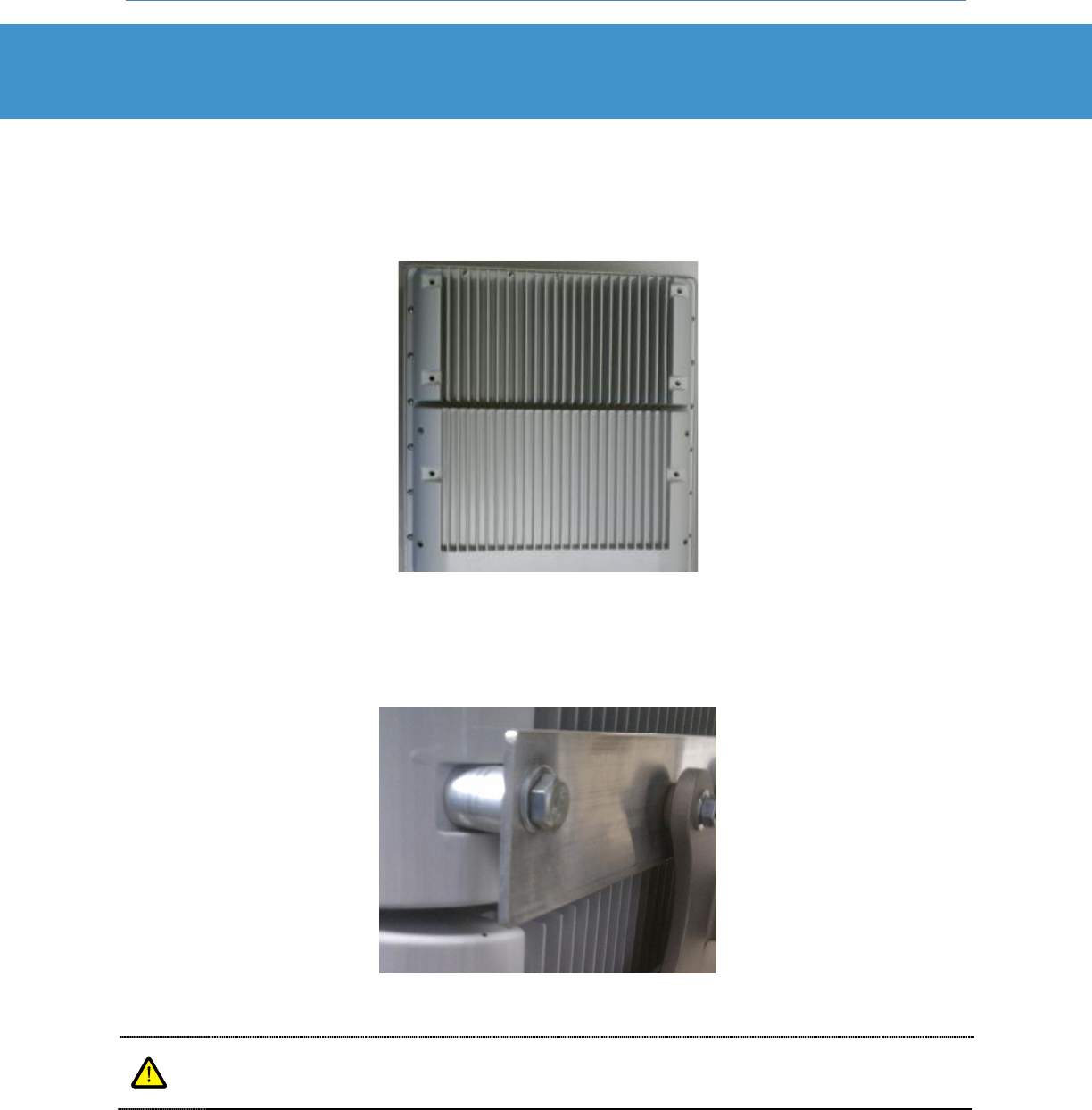
The back side of the base station includes 6 metric M8-1.25 threaded mounting holes, as shown in
Figure 4.
Figure 4: Base Station Mounting Holes
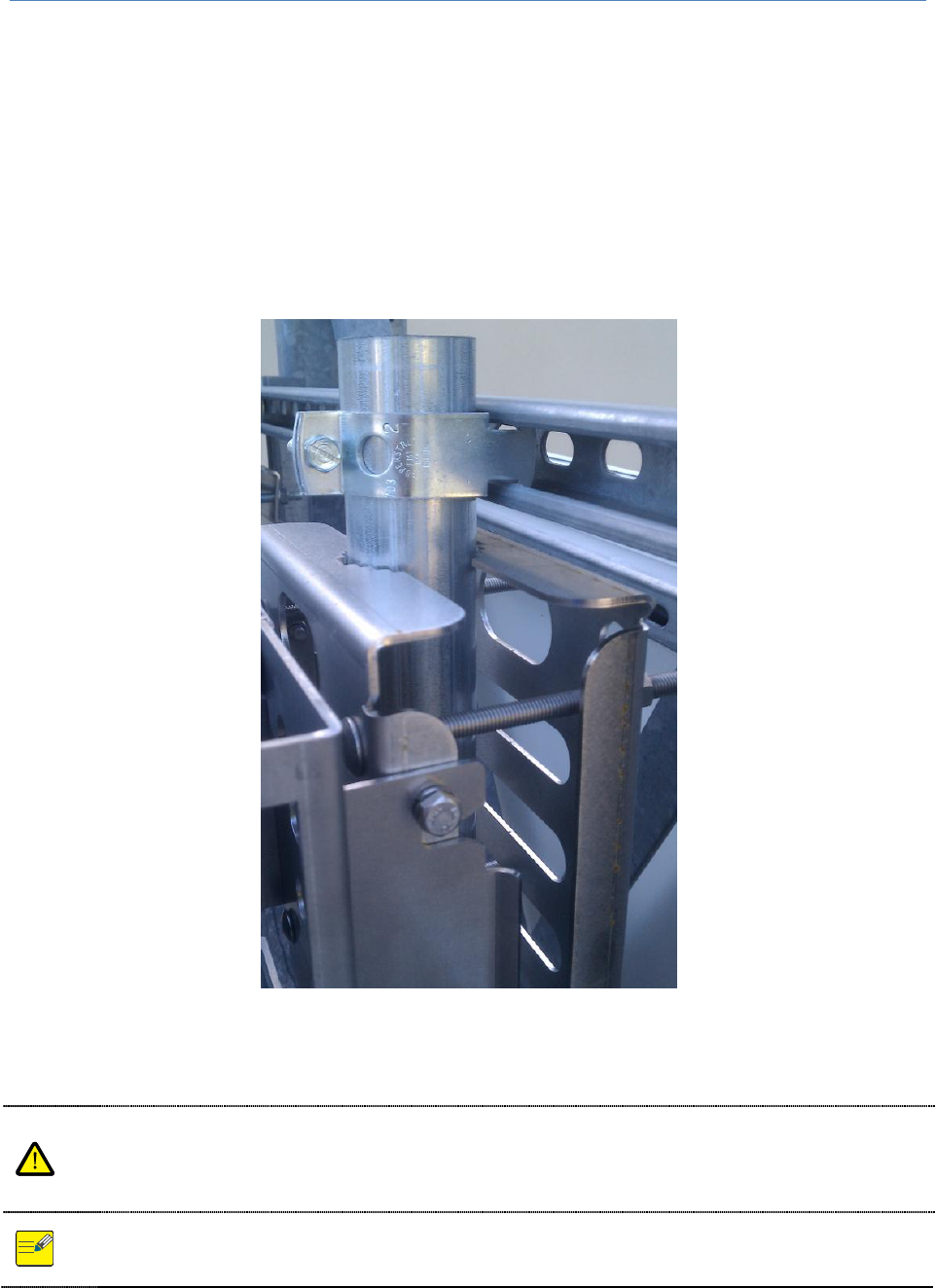
Because the mounting holes are recessed, provisions must be made to provide for spacing between the
mounting points and the mounting bracket or surface, as exemplified in Figure 5.
Figure 5: Example of Mounting Point with Spacing Hardware
It is imperative that proper airflow be maintained on all sides of the base station and that all
heat sinks remain unobstructed. In the case of wall or surface mounting a minimum of 2” of
space should be maintained between the base station and mounting surface.
Quantum 2200 Installation Guide v2.1
Page 16
3.2 The Pole-Mount Kit
The optional PureWave Quantum Base Station Pole Mounting Kit provides all hardware required for
installing the base station on a pole ranging from 2.5-5 inches in diameter. It is important to note that
the use of a pole mount in no way dictates that the base must actually be deployed on top of a long
pole, although in many cases it will in fact be. Alternatively the base station may be conveniently
attached to a short pole, which may then be easily mounted to a metal frame or struts that conform to
the specific deployment using commonly available hardware. An example of this is shown in Figure 6.
Figure 6: Example Deployment Consisting of Pole Attached to a Metal Frame
The PureWave Quantum Base Station Pole Mount Kit has been specifically designed to
handle the weight of the base station. However, it is critical that the full weight of the base
station plus mounting hardware be considered in designing the overall base station mounting
solution.
Fully assembled, the PureWave Quantum Base Station Pole Mount Kit weighs 16lbs (7.3kg).

Quantum 2200 Installation Guide v2.1
Page 17
If you have ordered the pole mounting kit then it was shipped in the same box as the base station.
Please locate the kit and compare its contents to Table 4.
Item
Quantity
Purpose
a) Front Pole Mount Plate
1
Grips pole along with back pole mount plate (b). The base
station mounting bracket also connects to this piece.
b) Back Pole Mount Plate
1
Grips pole along with front pole mount plate (a).
c) Base Station Mounting Bracket
1
Attaches to base station mounting holes, as well as to front
pole mount plate (a). A built-in handle facilitates carrying the
base station when attached.
d) Carriage Bolt SAE 3/8-16
Up to 12
Selection of carriage bolts ranging from 6” to 10”, fully or
partially threaded. Select a set of 4 that are appropriate to the
installation, and use with push nut (e), hex nut (g), and washer
(h) to fasten front (a) and back (b) mounting plates to pole.
e) Nylon Pushnut, 3/8
4
Slide onto carriage bolt (d) to prevent it from slipping out of
front mounting plate (a) while fastening hex nut (g) and washer
(h).
f) Nylon Tie Wrap
2
Use to temporarily affix mounting hardware to pole during the
installation process.
g) Hex Nut, SAE 3/8-16
4
Use with carriage bolts (d) and split lock washers (h) as
described.
h) Split Lock Washer, SAE 38
4
Use with carriage bolts (d) and hex nuts(g) as described.
i) Hex Bolt, Metric M8 -1.25 X 16
6
Use with M8 split lock washers (k) to fasten base station
mounting bracket (c) to base station.
j) Hex Bolt, Metric M8 -1.25 X 25
4
Use with M8 split lock washers (k) to fasten base station
mounting bracket (c) to front pole mount plate (a).
k) Split Lock Washer, Metric M8
10
Use with M8 bolts (i, j) as described.
Table 4: PureWave Quantum Base Station Pole Mount Kit Contents
3.2.1 Pole Mount Installation Procedure
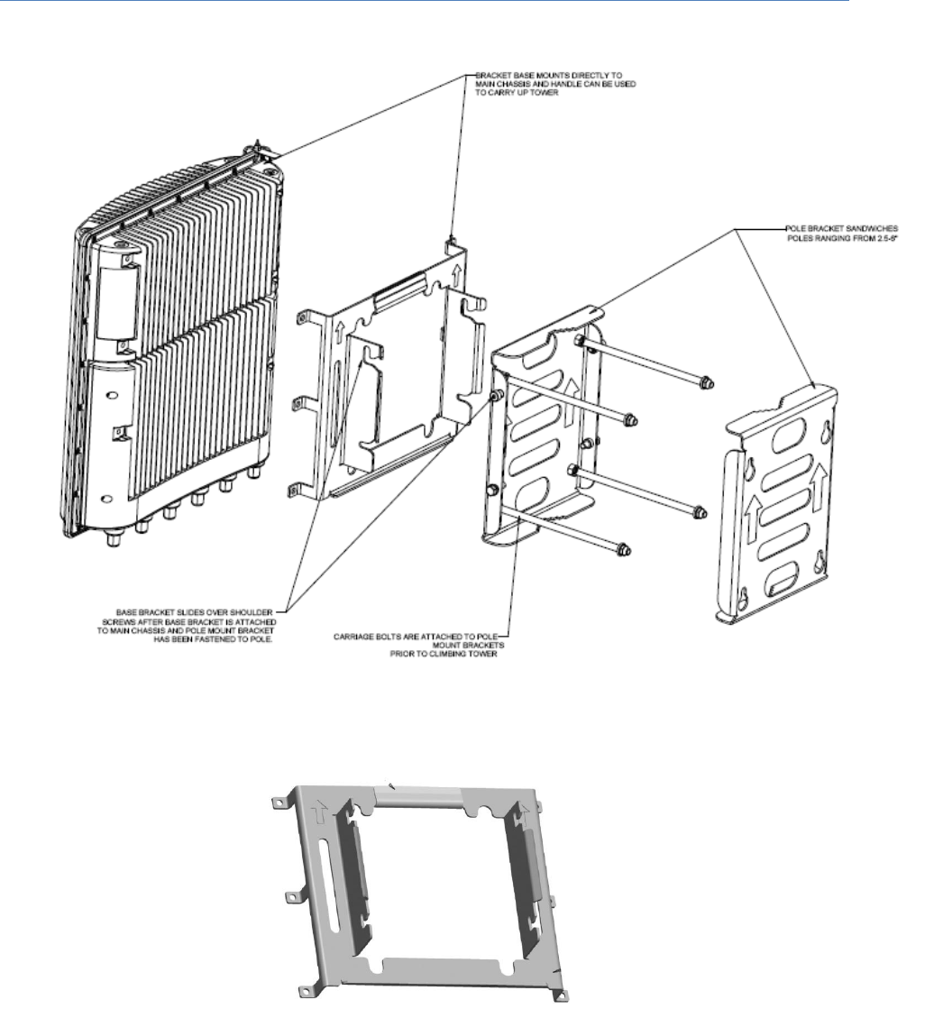
Figure 7 illustrates how the entire pole-mounting mechanism connects together and to the base station.
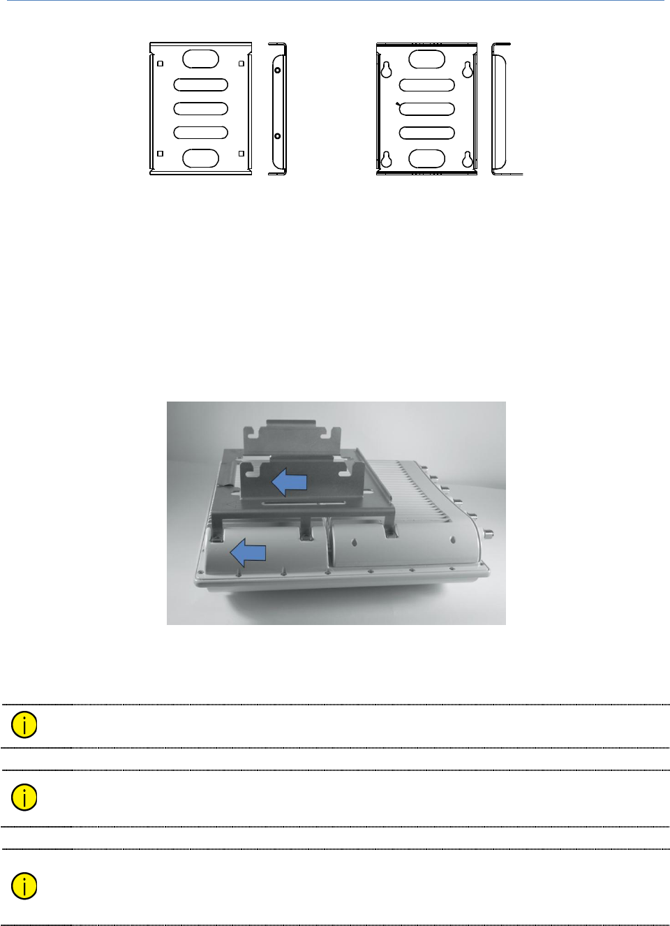
The pole mount mechanism consists of a base station bracket (Figure 8) that attaches to the mounting
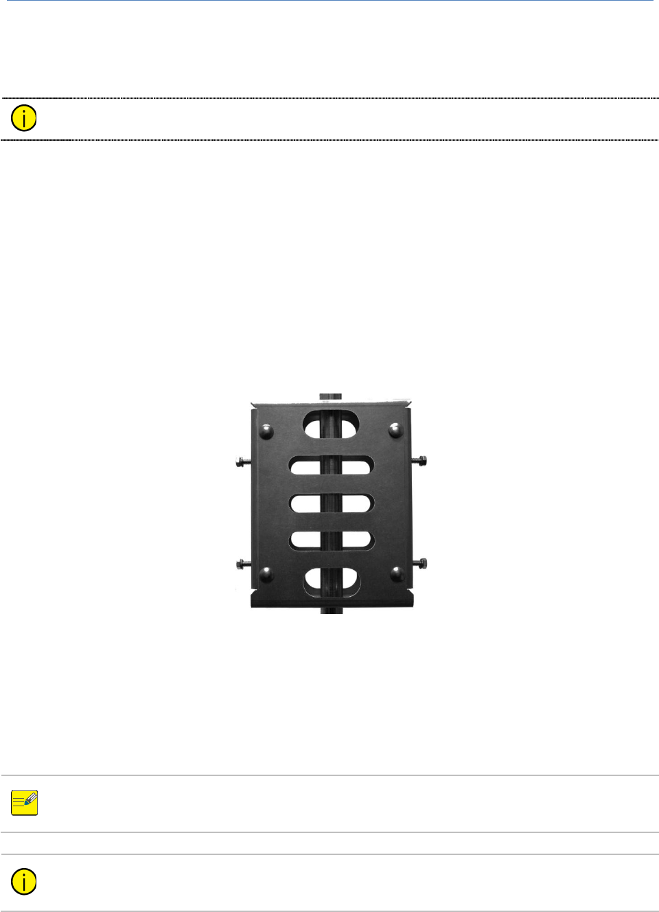
points on the back of the base station, and a pair of pole-mount plates (Figure 9) that grip the pole and
to which the base station bracket attaches. Table 4 indicates where each included piece of hardware is
to be used and should be strictly followed to ensure a secure and proper installation.
Quantum 2200 Installation Guide v2.1
Page 18
Figure 7: Base Station Pole Mount Assembly Diagram
Figure 8: Base Station Mounting Bracket
Quantum 2200 Installation Guide v2.1
Page 19
Figure 9: Pole Mounting Plates
First mount the Base Station Mounting Bracket (Figure 8: Base Station Mounting Bracket) to the base
station using the provided hardware, as indicated in Table 4. When installing the base station mounting
bracket onto the base station, be sure to align it as shown in Figure 10. Note that the bracket is
designed for upright mounting of the base station; that is, mounting with the connectors facing down.
Tighten the bolts to a torque of 30 in-lbs.
Figure 10: Base Station Mounting Bracket Alignment
The base station bracket may be mounted to the base station ahead of time as it has a built-
in handle that facilitates its transportation and carrying the base station up a tower.
To improve the effectiveness of connector waterproofing and to optimize the base station’s
thermal performance, it is recommended that the base station be mounted in an upright
position, with the connectors at the bottom.
Note that the base station bracket is designed specifically to attach to the 6 recessed
mounting holes on the base station, and hence can be useful in a variety of mounting
scenarios. However, use of this bracket without the pole mounting plates designed
specifically to accompany it is at the sole discretion and responsibility of the customer.
Front Mounting Plate Rear Mounting Plate
Quantum 2200 Installation Guide v2.1
Page 20
The next step is to mount the front and back pole mount plates (Figure 9) to the pole, using the
provided hardware as indicated in Table 4.
Nylon tie wraps have been provided for convenience to temporarily affix the front mounting
plate to the pole during the installation process.
A selection of carriage bolts has been provided to accommodate a variety of pole diameters. Select a
set of 4 bolts that enable a secure fit to your pole. Insert each carriage bolt through the front mounting
plate and slide a pushnut onto it to temporarily hold it in place. Slide the back mounting plate onto the
carriage bolts, sandwiching the pole in-between, then add lock washers and hex nuts tightened to a
torque of 30 in-lbs.
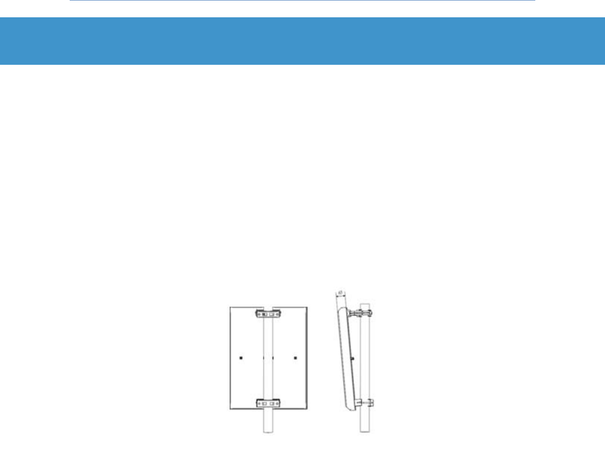
Insert the four provided M8-1.25x25 hex bolts along with M8 split lock washers into the side holes of the
front pole mounting plate and leave them loose for now. These bolts provide the attachment point for
the base station mounting bracket to the pole mount subassembly. The completed subassembly is
shown in Figure 11.
Figure 11: Pole Mount Subassembly
Finally, using the handle on the base station mounting bracket, lift the base station subassembly onto
the pole mount subassembly and hang it on the four side mounting bolts. Torque the bolts to 30 in-lbs.
For this and other installations in this manual, a suitable anti-corrosion lubricant should be
applied to all exposed metal surfaces. For your convenience a tube of Bostik NEVER-SEEZ®
has been provided in the PureWave Quantum Base Station Basic Installation Kit.
Note that these types of lubricants tend to be “messy” and “sticky” to apply due to the
nature of their intended application. Always read the labels or instructions provided and take
necessary pre-cautions during application.
Quantum 2200 Installation Guide v2.1
Page 21
4 Mounting the Antennas
PureWave Quantum Base Stations can be deployed with virtually any type of antennas that operate in
the relevant frequency band and that meet regional regulatory standards. Antenna mounting
procedures will vary by model and manufacturer, so we refer the installer to the instructions that came
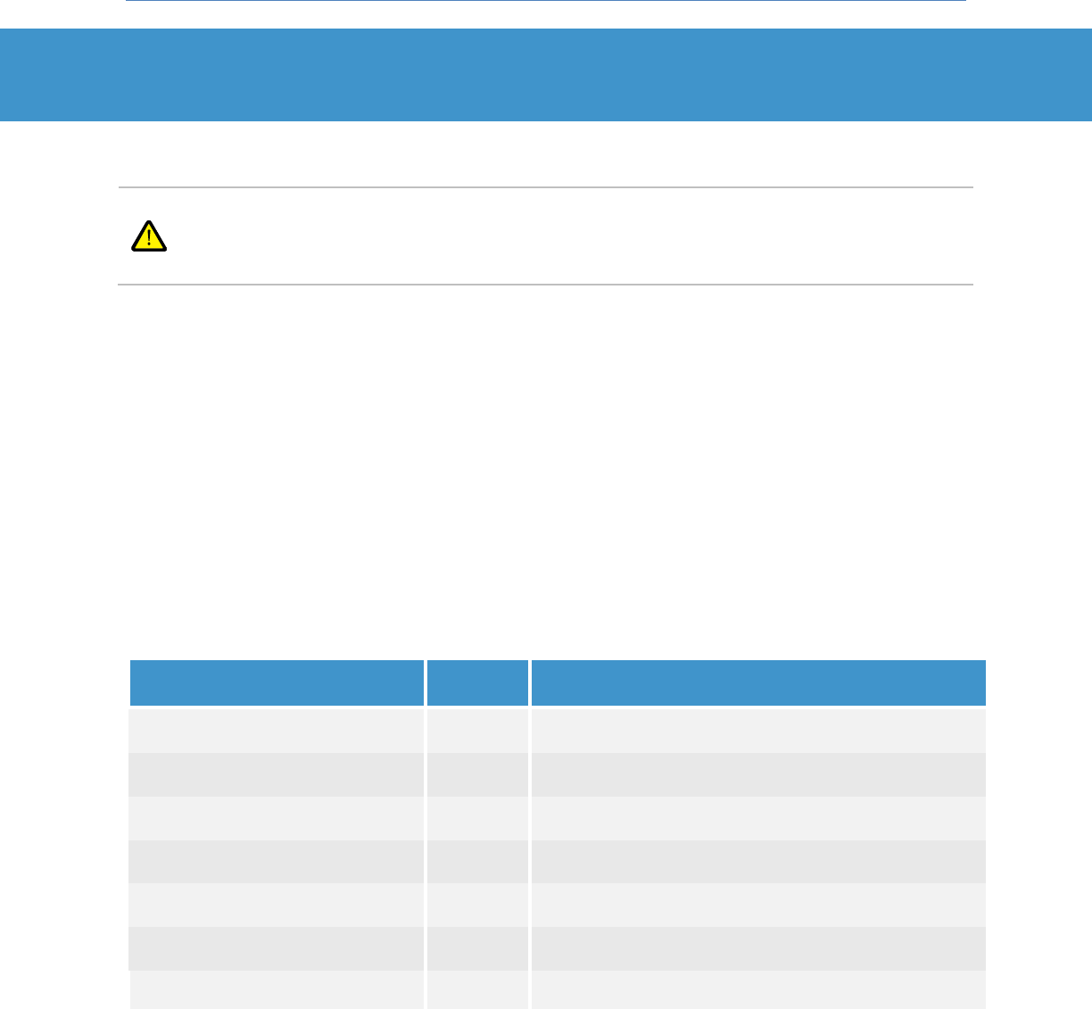
with the antenna(s) and/or antenna mount(s) for their secure and proper installation (Figure 12)
As a general rule the antennas should be installed as close as practical to the base station. This
minimizes signal loss which is directly proportional to cable length. In addition, a high-quality, low-loss
coaxial cable capable of propagating the relevant frequencies (such as Hyperlink Technologies P/N
CA3N100 or Times Microwave LMR 400) should be utilized between the antenna and base station.
In the event that the base station cannot be co-located with the antennas the choice of cable is even
more important, as signal losses can be significant. For example, LMR 400 cable has an attenuation loss
of 6.8dB per 100ft at a frequency of 2.5GHz. It is important that cable loss be computed and understood
to ensure that adequate range will still be achieved for your deployment needs.
Figure 12: Pole-Mounted PureWave Antenna
Quantum 2200 Installation Guide v2.1
Page 22
5 Connecting the Antennas to the Base Station
5.1 Installation of Lightning Surge Protectors
In most environments it is essential for the base station to be installed with external
protection against surges caused by lightning on the antenna cables. PureWave therefore
recommends that suitable surge protectors be installed on each base station antenna
connector.
For an indoor installation of the Base Station, surge protection devices should be installed at the
entrance to the building that houses the Base Station. For an outdoor installation they are installed on
the relevant connectors.
The optional PureWave Quantum Surge Protection Kit has been developed for your convenience and
provides hardware designed to protect the base station from surges on its antenna connectors.
PureWave strongly recommends the use of this kit. It is important to note, however, that every
environment and installation is different. Therefore, it is the responsibility of the customer and the
installer to ensure that sufficient protection is employed, whether or not this kit is utilized.
If you have ordered the PureWave Quantum Surge Protection Kit then it was shipped in the same box as
the base station. Please locate the kit and compare its contents to Table 5.
Item
Quantity
Purpose
(a) Connector Weather Proofing Kit
1
Contains tape and butyl rubber for weatherproofing the
antenna connectors and surge arrestors (c).
(b) Connector, Insulated Crimp Ring
Terminal, Lug, AGW 10-12, #10
2
Used to create ground connections between Quantum BS
Surge Arrestor (c) and ground terminal on BS.
(c) Surge Arrestor, RF, N-Type M/F
2
Attaches to a base station antenna connector on one side,
and an antenna cable on the other side.
(d) Lubricant, NEVER·SEEZ® Regular
Grade 1OZ
1
Anti-corrosion / anti-seize lubricant for use on exposed
metal surfaces.
(e) External Tooth Lock Washer,
Metric, M5
2
Hex nut (f) to fasten crimp rings (b) to Surge Arrestor (c).
(f) Hex Nut, Metric, M5-.8
2
Use with washer (e) to fasten crimp rings (b) to Surge
Arrestor (c).
(g) DC Surge Protection
1
Quantum Base Station DC Power Supply Surge Protection.
Table 5: PureWave Quantum Surge Protection Kit Contents

Quantum 2200 Installation Guide v2.1
Page 23
Specifications for the PureWave Quantum Surge Protection Kit are summarized in Table 6.
Surge Protector Feature
Specifications
Surge Capabilities
IEC 1000-4-5, 8/20μs @ 10kA
Frequency Range
2-6GHz
Return Loss
> 20dB
Insertion Loss
≤ 0.2dB
RF Power Limit
10 Watts
Max Temperature
-40oC to +85oC
Relative Humidity
0-100% condensing
Surge Throughput Energy
≤ 0.5μJ (6kV/3kA 8/20μs)
Peak Let-Through Voltage
±3V (6kV/3kA 8/20μs)
Table 6: PureWave Quantum Surge Protection Kit Specifications
The following surge protector installation procedure is specific to the PureWave Quantum Surge
Protection Kit. If you have chosen to use alternative surge protection hardware then please follow the
instructions received with that hardware to ensure proper installation. However, we still recommend
that you review the procedure below, as much of it will still be relevant.
Step 1:
Screw one surge arrestor onto each base station antenna connector ANT-1 and ANT-2 and
tighten to a torque of 12-15 in-lbs.
Step 2:
Weatherproof each surge arrestor connection to the base station before proceeding with the
next step. Please refer to Appendix A for a general discussion and guidelines on
weatherproofing connections.
Step 3:
Place the grounding bar over the row of surge arrestors such that the two ground terminal
screws are facing the bottom of the base station, and secure in place with the lock washers
and nuts that came packaged with each surge protector. Tighten each nut to a torque of 30
in-lbs.
Step 4:
Wire ground connections from the ground bar terminals to the base station connector panel
grounding terminal using the provided crimp rings and hardware. Base station grounding
procedures are covered in Appendix A.
Quantum 2200 Installation Guide v2.1
Page 24
5.2 Connecting the Antennas to the Base Station
The base station has two N-type antenna connectors that must be attached to each installed antenna
using high-quality coaxial cable, as discussed in Section 4. The number of connectors/adapters used
should also be minimized as they are especially lossy. Most industrial-grade antennas, including all
PureWave antennas, utilize N-type connectors. Regardless of the antenna-side connector type, it is
important to obtain or construct cables with the correct respective terminal types and of the correct
length to avoid the need for additional connectors or adaptors.
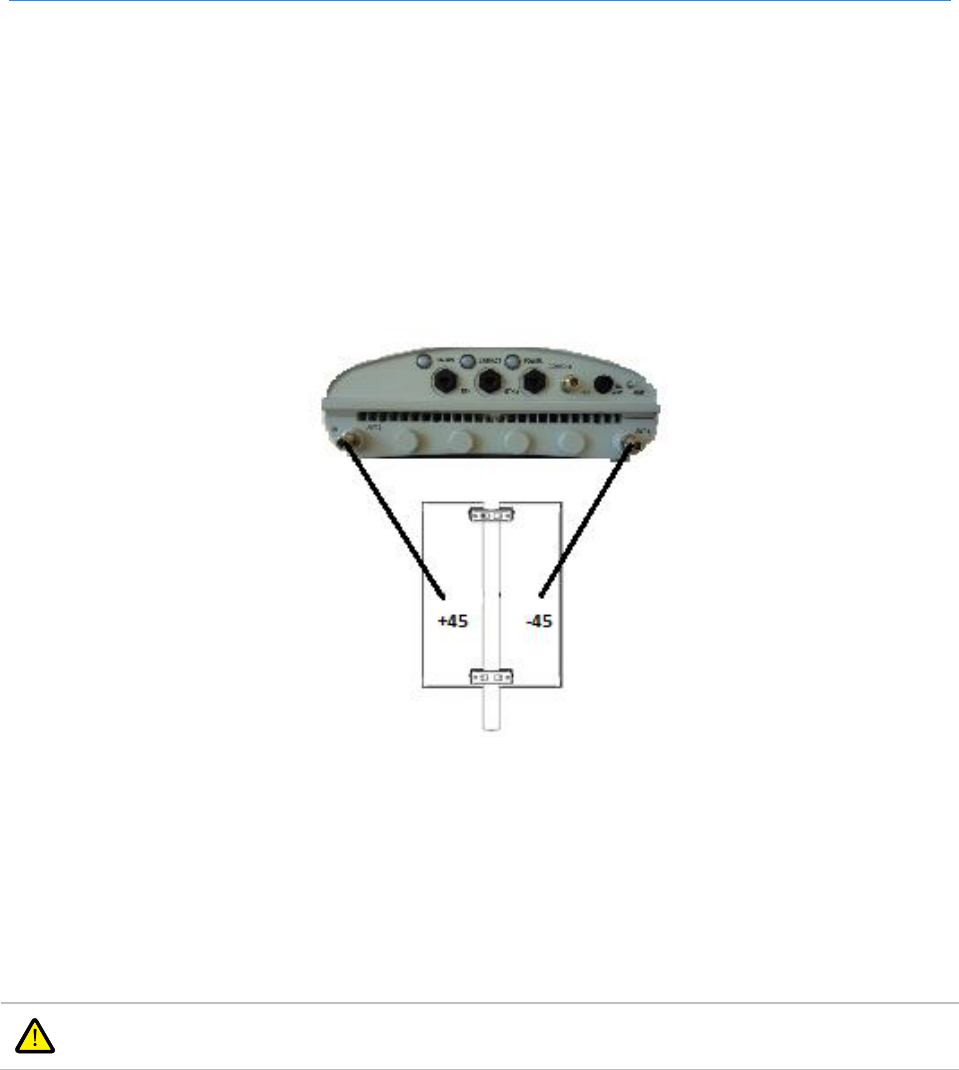
Figure 13 Antenna Connection
Prepare and run 2 low loss coax cables from the base station to the antenna. Connect each base station
(or surge arrestor) connector to the corresponding port number on the installed antennas. All antenna
ports must be connected (Figure 13).
Finally, weatherproof every connector. Please refer to Appendix A for a general discussion and
guidelines on weatherproofing connections.
Thorough weatherproofing of all connections is extremely important to ensure long-term
base station operation as well as validation of the warranty.
Quantum 2200 Installation Guide v2.1
Page 25
6 Installing the GPS Antenna
WiMAX base stations utilize GPS (the Global Positioning System) to maintain tight synchronization and
coordination among themselves in a network. This assures that all base stations in the network transmit
and receive in harmony, as they must all utilize the same Downlink / Uplink Ratio.
6.1 Selecting and Mounting a GPS Antenna
PureWave Quantum Base Stations incorporate an integrated GPS receiver which must be connected to
an external GPS antenna view of a number of GPS satellites. Installation location flexibility and the
amount of tolerable obstruction are heavily dependent upon the quality and capabilities of the chosen
antenna.
The choice of GPS antenna is an important one, as there are many models available in the
market for many purposes, and hence some are very inexpensive but also low gain and/or
low quality. A poor GPS antenna can easily become the point of failure of your system.
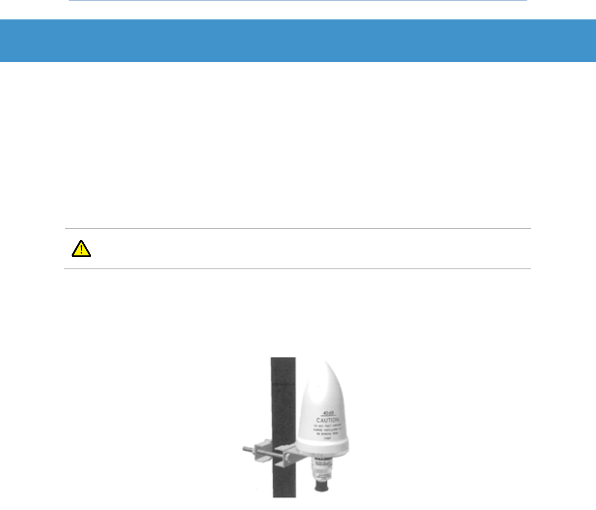
PureWave strongly recommends the use of a high-quality GPS antenna and therefore offers an optional
GPS Antenna Kit, featuring a GPS antenna with integrated 40dB low-noise amplifier and mount kit
(Figure 14).
Figure 14: Optional GPS Antenna and Mounting Kit
If you have ordered the GPS Antenna Kit it was shipped in the same box as the base station. The
optional GPS Antenna Kit it includes all required mounting hardware and instructions and we refer the
installer to that documentation for secure and proper installation. Similarly, if an alternative GPS
antenna has been chosen, please refer to the instructions provided by the manufacturer for proper
mounting procedures.

Quantum 2200 Installation Guide v2.1
Page 26
6.2 Connecting the GPS Antenna to the Base Station
The base station utilizes an N-type GPS antenna connector. The GPS antenna that comes as part of the
optional GPS Antenna Kit also has an N-type connector. Prepare a high-quality coaxial cable of the
appropriate length and with the appropriate connector types for use in connecting the GPS antenna to
the base station.
Connect the coaxial cable from the external GPS antenna to the N-type female connector marked “GPS”
on the base station, and weatherproof the connectors. Please refer to Appendix A for a general
discussion and guidelines on weatherproofing connections.

Quantum 2200 Installation Guide v2.1
Page 27
7 Connecting Ethernet and Serial Console Cables
7.1 The PureWave Basic DC Installation Kit
Each PureWave Quantum Base Station is shipped with the PureWave Quantum Basic DC Installation Kit,
which contains hardware and components required for connecting and waterproofing the Ethernet
ports, console port, the power port, and the grounding terminal. This kit has been shipped in the same
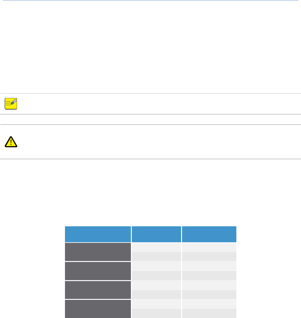
box as the base station. Please locate it and compare its contents to Table 7.
Table 7: PureWave Quantum Basic DC Installation Kit Contents
Item
Quantity
Purpose
a) 6” Cat 5e Cable
1
Connects base-station serial/console port
connector to DB9 to RJ45 adaptor (c)
b) DB9 Female to DB9 Female Serial Cable
1
Connects serial consol/terminal to DB9 to RJ45
adaptor (c)
c) Network DB9 Female to RJ45 Adaptor
1
Couples cables for serial console connection (a, b)
d) DC Connector 4 Pin Female Plug
1
Part of DC power connector subassembly (d, e, f)
e) 14-18 AWG Circular Socket Crimp Contact
4
Part of DC power connector subassembly (d, e, f)
f) Cable Clamp Connector
1
Part of DC power connector subassembly (d, e, f)
g) RJ45 IP67 Weatherproof Housing
3
Weatherproof housing subassemblies for ETH-1,
ETH-2, and Console Connectors
h) Insulated Crimp Ring Terminal
1
Attaches to base station ground terminal using
provided hardware (l, m, n)
i) NEVER-SEEZ® Lubricant, 1oz tube
1
Anti-corrosive lubricant
j) Weatherproofing Kit
1
For all connectors. Recommended
weatherproofing procedures are provided in this
document.
k) RJ45 Plug Shielded Connector
6
Provided for use in creating custom-length CAT-5
cables for ETH1, ETH2, and Console connections.
l) Washer, Metric M5 Flat
1
Part of crimp ring subassembly (h, l, m, n)
m) Washer/Metric, M5 External Tooth Lock
1
Part of crimp ring subassembly (h, l, m, n)
n) Hex Nut Metric, M5-.8
1
Part of crimp ring subassembly (h, l, m, n)
o) Extra Hardware Kit
1
A variety of extra parts for convenience
Quantum 2200 Installation Guide v2.1
Page 28
7.2 Preparing the Ethernet and Console Cables
ETH-1 and ETH-2 connectors should both be run from the base station to the operator’s network
equipment. The CONSOLE connection may be connected for initial provisioning and thereafter on an as-
needed basis or it may be permanently connected as with the Ethernet connections. Please take into
consideration that the RS-232 console connection is less tolerant to noise and interference in long cable
runs than the Ethernet interfaces.
The maximum length of the Cat-5e cables connecting the Ethernet or console ports on the
base station to the Service Provider’s network equipment is limited to 100m (328ft).
When the Base Station is mounted outdoors it is important to use outdoor rated Category-
5e+ Gigabit Ethernet Cable, such as Commscope Ultra IITM, and shielded outdoor rated metal
RJ-45 connectors. Six high-quality shielded connectors have been included in the PureWave
Quantum Basic Installation Kit.
Prepare and connect two Cat 5e+ cables from the ETH-1 and ETH-2 ports to the operator’s network
equipment, and one more for the CONSOLE port if desired.
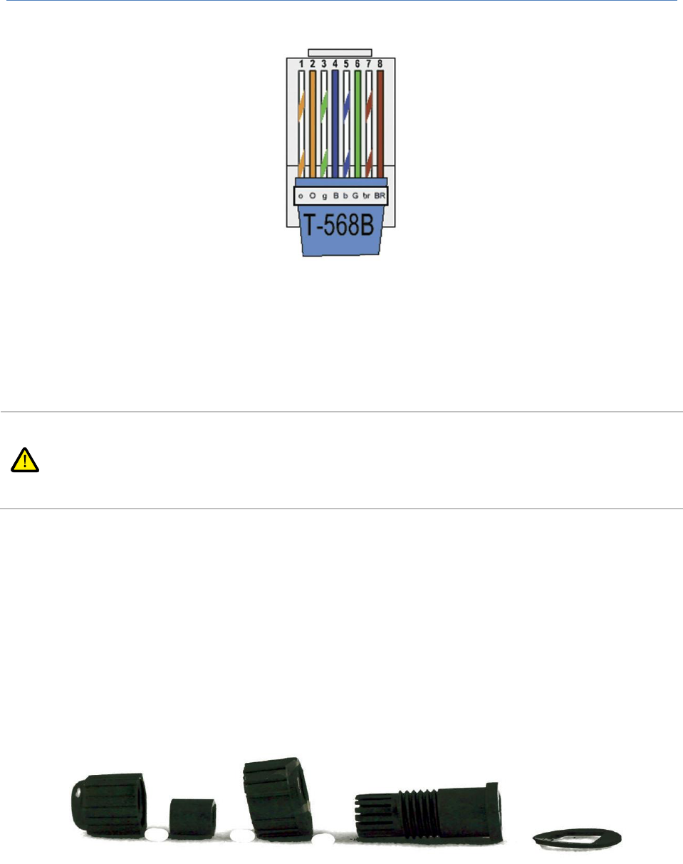
In preparing the Cat 5e+ cables, terminate each at the base station in accordance with the T-568B wiring
standard, as described in Table 8 and illustrated in Figure 15.
Pair Number
Wire Color
Pin Number
1
white / blue
5
Blue
4
2
white / orange
1
Orange
2
3
white / green
3
green
6
4
white brown
7
brown
8
Table 8: Cat 5e+ Connector Pinout
Quantum 2200 Installation Guide v2.1
Page 29
Figure 15: T-567B RJ-45 Connector
7.3 Weatherproofing the Ethernet and Console Connections
If the CONSOLE port is not to be permanently connected then it should remain tightly capped
for the time-being. A serial cable, a 6” Cat-5 cable, and a DB9 to RJ-45 adapter has been
supplied with the PureWave Quantum Basic DC Installation Kit for bring-up and provisioning
purposes utilizing the CONSOLE port. Please refer to the PureWave Quantum User Manual
for additional information.
A set of three RJ-45 IP67 weatherproof housing assemblies have been supplied as part of the PureWave
Quantum Basic DC Installation Kit for the purpose of weatherproofing the Ethernet and console
connectors. The procedure for installation of the housing onto each cable and connector is provided
below. Note that at least one end of the cable should be crimped with a RJ-45 connector only at the end
of the procedure.
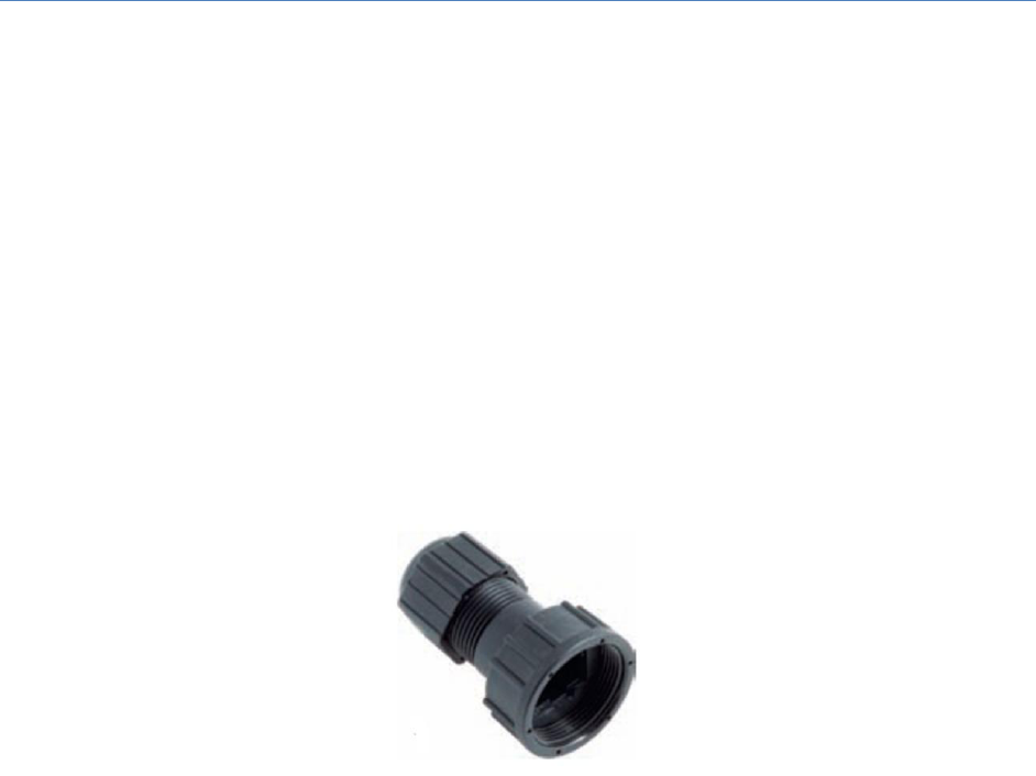
Please refer to Figure 16 during the following procedure, as it shows the interconnection and orientation
of each part in the assembly.
Figure 16: RJ-45 IP67 Weatherproof Housing Assembly
Quantum 2200 Installation Guide v2.1
Page 30
Step 1:
Slip the Sealing Nut onto the RJ-45 cable.
Step 2:
Place the screw nut onto the housing with the threads facing forward
Step 3:
Insert the seal into the housing
Step 4:
Insert the cable through the seal and housing exiting the front of the housing
Step 5:
Strip cable sheath
Step 6:
Crimp the RJ 45 plug onto the cable
Step 7:
Pull the cable back so the plug fits into the housing.
Step 8:
Secure the sealing nut in place
Step 9:
Stick the gasket onto the front end of the housing
The fully assembled connector is shown in Figure 17 and can now be attached to each base station RJ-45
connector thus creating a weather protected connection. Additional weatherproof wrapping, as
described in Appendix A is still, however, recommended.
Figure 17: Assembled RJ-45 IP67 Weatherproof Housing

Quantum 2200 Installation Guide v2.1
Page 31
8 Connecting DC Power and Ground
8.1 Base Station Single-Point Grounding
Extensive analysis and investigation of installations has led to the belief that the root cause at the heart
of the majority of power-related failures is likely to be the presence of multi-point grounding of
equipment. Single point grounding eliminates ground voltage differentials and thus dramatically
increases equipment survivability during surges.
Single point grounding requires that the grounding leads from antennas, base station, and surge
protection devices for a particular sector are bonded together at the same point on the tower or in the
shelter, in the case of an indoor installation. It is not necessary to bond all sectors together.
An insulated crimp ring has been supplied as part of the PureWave Quantum Basic DC Installation Kit
(Table 7), along with the hardware required to mount it to the base station GND terminal connection.
Furthermore, if the optional PureWave Quantum Surge Protection Kit (Table 5) has been installed then it
includes a set of crimp rings for mounting on the ground terminals of the supplied grounding bar.
Conductors from each installed crimp ring should be connected together, and then tied to a single-point
common grounding point.
The following grounding guidelines apply, whether or not the PureWave Quantum Surge Protection Kit
has been installed:
Surge protection devices generally connect to ground by using a ground wire. Cut any extra
ground wire length when finished connecting it to the single point earth ground.
Never loop or coil up the ground wire, and avoid sharp bends. Always connect it straight to
ground.
A good earth ground impedance is less than 1.0 ohm.
Measure ground impedance at the point where the protector ground wire is connected and not
at the ground rod.
Connect the protector ground wire and equipment ground (both power ground and telecomm.
ground) to a single common ground.
Make sure all connections are fastened securely.
8.2 Preparing the DC Power Connector
The DC power source to a PureWave Quantum Base Station must be capable of delivering up to 10
Amps of current at -48 VDC. The base station requires ~6 Amps max at -48VDC (range -40VDC to -
57VDC, -38VDC min).
The power connector used on the base station will accommodate 14 to 18 gauge wire. Remember to
take account of the voltage drop when running long power cable runs. For example, for 18 AWG and a
cable length of 100 feet, a nominal 48VDC supply delivering into a 6A load will have a voltage drop of 9.3
volts.
Quantum 2200 Installation Guide v2.1
Page 32
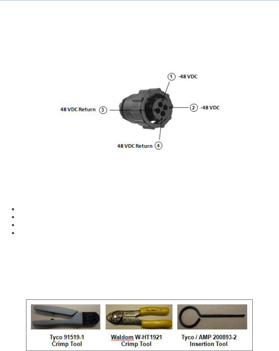
This DC power connector assembly has been provided as part of the Basic DC Installation Kit (Table 7)
and consists of a 4-pin female power connector plug, a set of crimp contacts, and a cable clamp. The
connector with pin assignments is shown in (Figure 18).
Figure 18: IP67 DC Power Connector and Pin Assignments
To successfully complete the power cable assembly you will need the following tools (not provided).
Wire-strippers
Needle-nose pliers
Phillips Screwdriver
Crimping tool
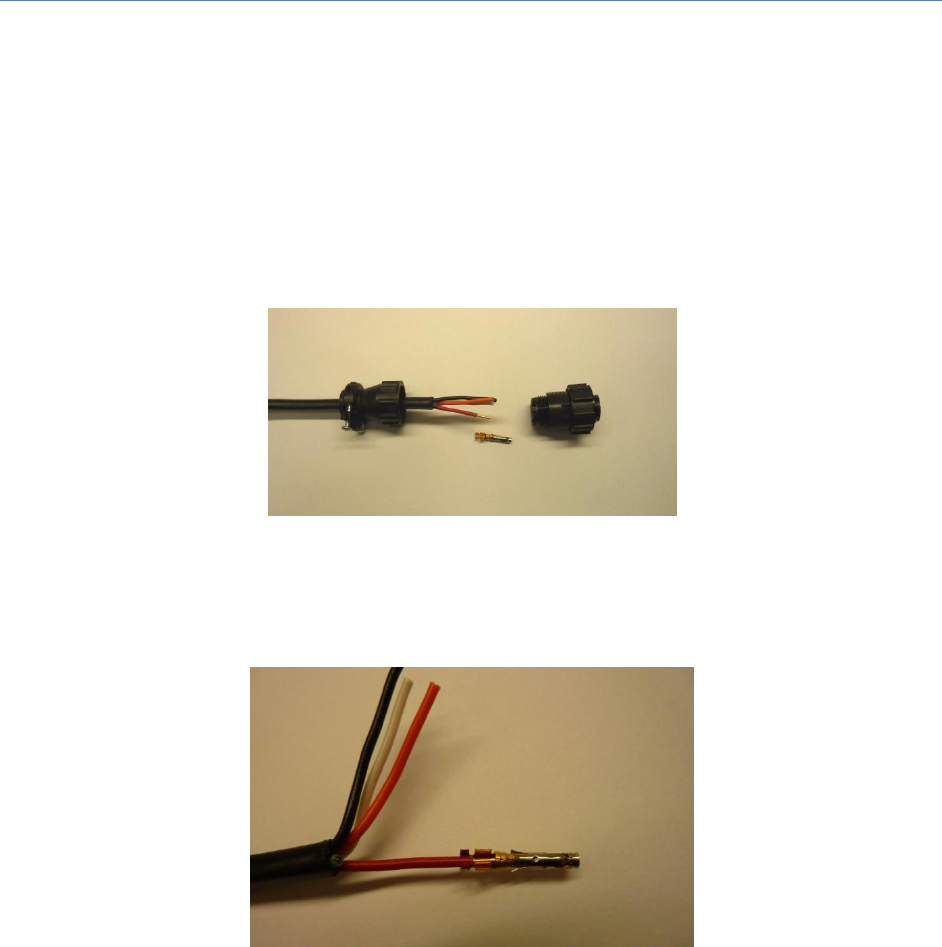
The Tyco 91519-1 Crimp Tool was specifically designed for the pins of the Quantum power connector.
However, due to its high cost we have focused on a procedure for creating the connector with the much
more affordable Waldom W-HT1921 Crimp Tool and plus the Tyco / AMP 200893-2 Insertion Tool. All
are shown in Figure 19. If you choose to use the optional Tyco crimp tool then please follow the
instructions included with the tool for the proper crimping procedure.
Figure 19: Crimp and Insertion Tools for the DC Power Connector
Quantum 2200 Installation Guide v2.1
Page 33
Step 1:
Use wire strippers to remove about 1/4 inch of insulation from each wire and approximately
1” of outer cable insulation. It is important that each wire be the same length, with equal
lengths of stripped wire.
Step 2:
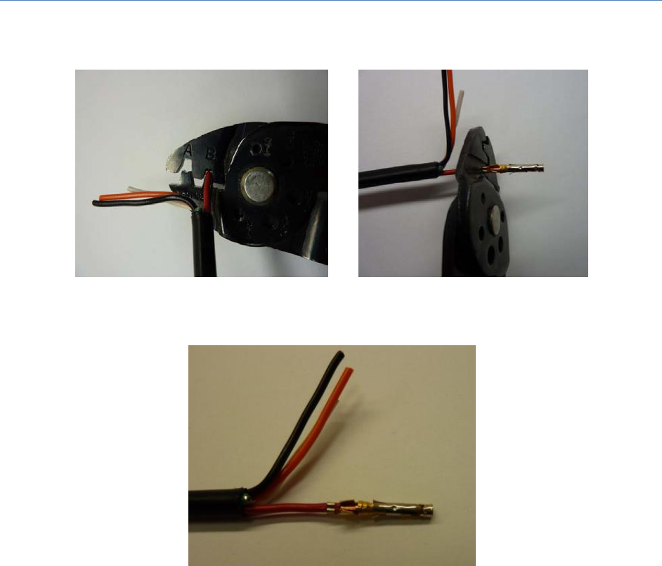
Slide the circular socket connector over the power cable as shown in Figure 20.
Figure 20: Slide connector onto cable before crimping.
Step 3:
Place stripped wire into circular socket crimp contact such that insulated wire is present at
the first crimp location and bare wire is present at the second crimp location (Figure 21).
Figure 21: Wire properly inserted into circular socket crimp contact
Step 4:
Using the Waldom crimping tool in crimp head location B, squeeze carefully, assuring that
the first crimp location is forming properly before wielding full pressure. Give it a slight tug
to ensure that it is secure and that the wire is tightly crimped into place. The pin connector
crimp locations are U-shaped and must be placed in the crimper such that the open end of
the U-shape points toward the A/B locations. When forming the U-shaped crimp it is
important to ensure the crimp folds back on itself, creating a heart-shape. Please refer to
Figure 22 and Figure 23.
Quantum 2200 Installation Guide v2.1
Page 34
Figure 22: Side and top views of correct crimping technique
Figure 23: Properly completed first crimp
Step 5:
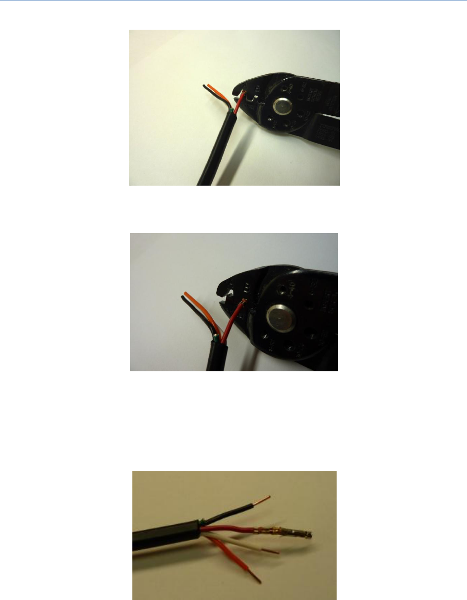
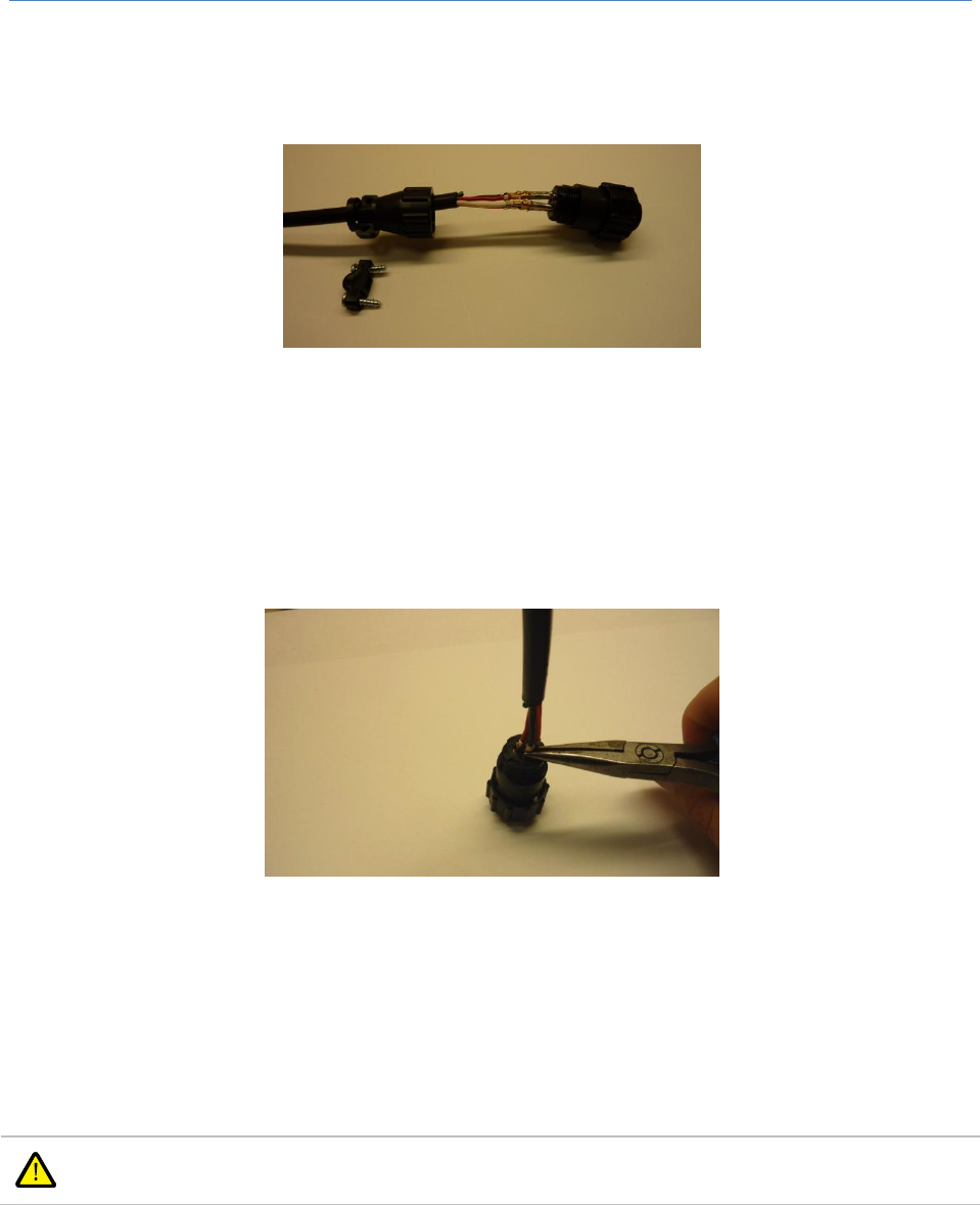
Crimp the cable again at the second crimp location by starting with the “A” side of the
crimping tool (Figure 24). Release crimping pressure when the second crimp location begins
to curl. Next place the second crimp location in section “B” of the tool (Figure 25) and
securely complete the crimp.
Quantum 2200 Installation Guide v2.1
Page 36
Step 6:
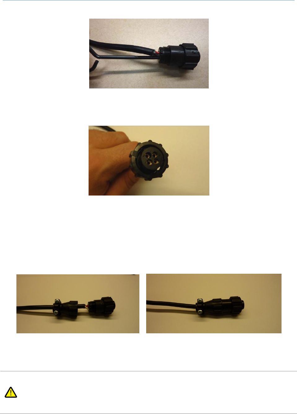
Using your fingers, insert the crimped pins into the corresponding holes of the DC power
connector plug (Figure 27). Be sure to match the pin-out as specified earlier.
Figure 27: Pins inserted into DC power connector
Step 7:
Next use needle nose pliers to insert the pins further by grabbing the first crimp location and
pushing all the way into the connector body. It helps if you place the connector face down
on a table to provide extra leverage. It is critical that the pins are pushed as far into the
connector body as possible. See Figure 28
Figure 28: Use needle-nose pliers to push the pins further into the plug.
Step 8:
Now use the insertion tool to secure the pins inside the connector plug (Figure 29). An
audible ‘click’ should be heard when the pin is fully inserted into the connector body.
Properly inserted pins will be visible from the front of the connected as shown in Figure 30).
Note: It is possible to over-insert the pin when using the pin insertion tool, so take care to
gently insert the ping into the connector body.
Quantum 2200 Installation Guide v2.1
Page 37
Figure 29: Use insertion tool to secure the pins in the plug.
Figure 30: Front view of plug with crimp pins properly inserted
Step 9:
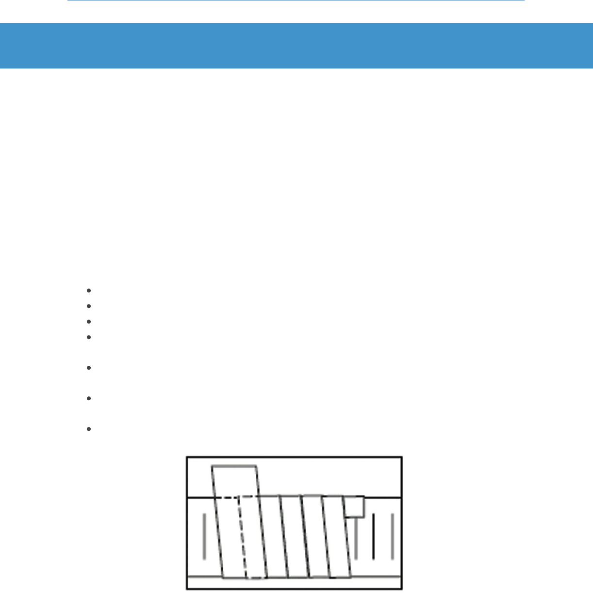
Complete the assembly by screwing the plug into the circular socket connector and secure
with the cable clamp by tightening the two strain-relief screws using a Phillips screwdriver.
The completed assembly is shown in Figure 31.
Figure 31: Completed Power Connector Assembly
Note that the base station does not have a power switch and will immediately power up if
the DC power connector is in place and power is applied. Please do not apply power to the
base station until all connections are made in accordance with the instructions in this guide.
Then, please refer to the PureWave Quantum Base Station User Guide for additional
instructions.
Quantum 2200 Installation Guide v2.1
Page 38
Appendix A Connector Weatherproofing
Required Materials
PureWave recommends that appropriate weather protection sealing be applied to all “outdoor”
installed elements of the system. Weatherproofing tape kits can very effectively seal the junction
between mating connectors. Proper and diligent weatherproofing not only protects the connection from
water damage, but also prevents vibrations from loosening the interface.
A wide range of weather protection materials and kits are commercially available. The PureWave
Quantum Basic DC Installation Kit and the Optional PureWave Quantum Surge Protection Kit each
include a weatherproofing kit that contains a variety of tapes along with general weatherproofing
guidelines.
General Guidelines for Working with Weatherproofing Tape
When applied, the tape must be above 32°F (0°C) to ensure adhesion.
Do not stretch the tape. Apply only enough tension to provide a smooth wrap.
Smooth each wrapped layer with your hands to ensure full adhesion.
Do not pull the tape to tear it - always cut it. Pulled tape eventually unravels, decreasing
protection.
Add extra final layers of tape in warmer climates where there will be long exposure to damaging
ultra violet (UV) rays. Two or three extra layers of tape will provide additional UV protection.
On vertical runs, the last wrap of 3/4” tape should be wrapped from the bottom to the top. This
provides a shingle effect.
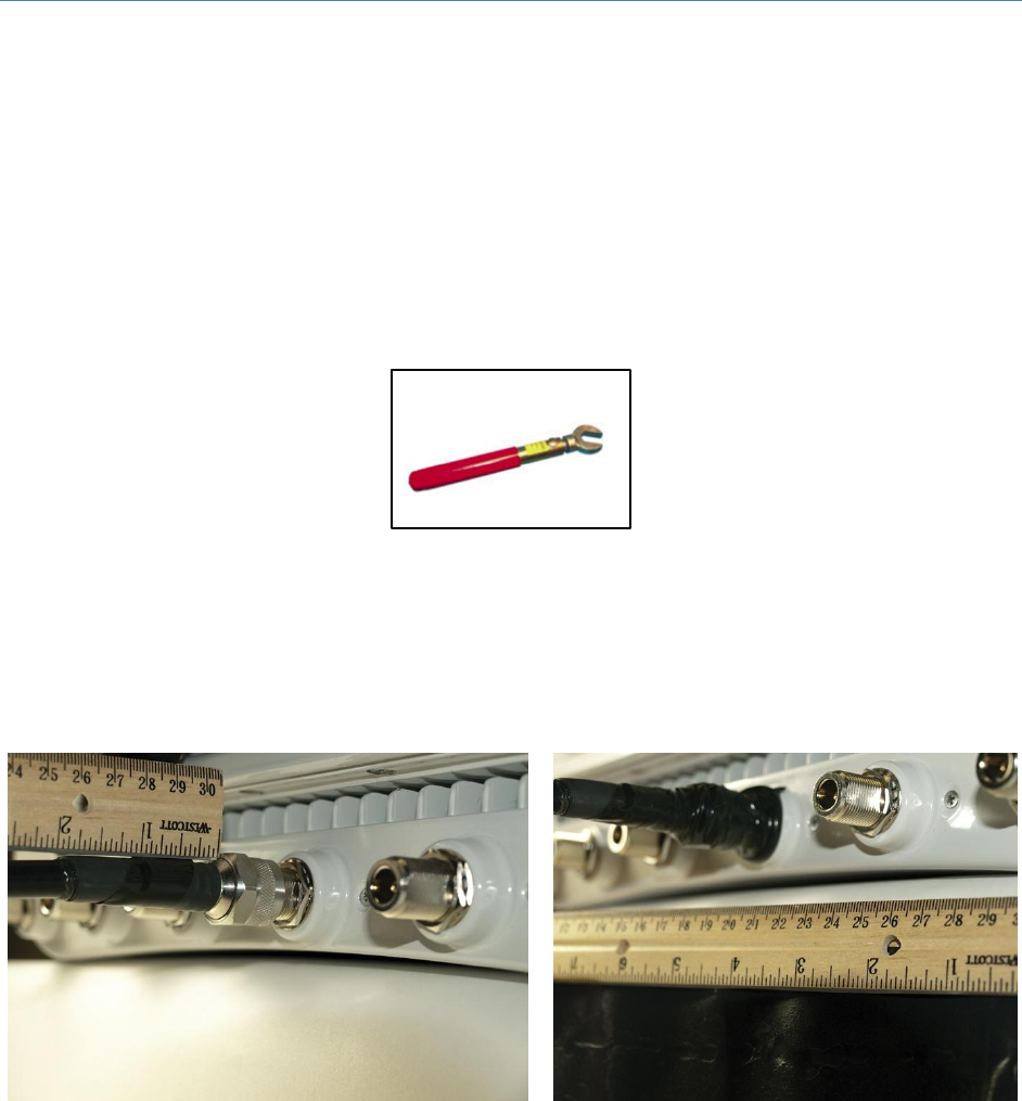
When wrapping tape, overlap the tape to half-width as shown in Figure 32.
Figure 32: Proper Weatherproof Tape Overlap
Quantum 2200 Installation Guide v2.1
Page 39
Weatherproofing Procedures
The following procedure is illustrated for an N-type antenna connector (without surge connector) but
applies to all connector types.
Step 1:
Tighten the connection with a torque wrench to the proper torque value (12-15lbs for an N-
type connector) to ensure that correct internal seals and surface contacts are made. One
recommended torque wrench for an N-Type connector is the Andre 244379 and is shown in
Figure 33.
Figure 33: Torque Wrench for N-Type Connector
Step 2:
Wrap the connection with a layer of 3/4” (19-mm) plastic tape, starting at 1” (25 mm) from
the connector. Overlap the tape to half-width as illustrated in Figure 32 and extend the
wrapping over the entire connector. Avoid making creases or wrinkles. Smooth the tape
edges. See Figure 34.
Figure 34: First Plastic Tape Layer
Step 3:
Cut a 5” (125-mm) length of rubber tape. Expand the width of the tape by stretching it such
that it will wrap completely around the connector and cable. Press the tape edges together
so that there are no gaps. Press the tape against the connector and cable. The tape should
extend 1” (25 mm) beyond the plastic tape on the cable (Figure 35).
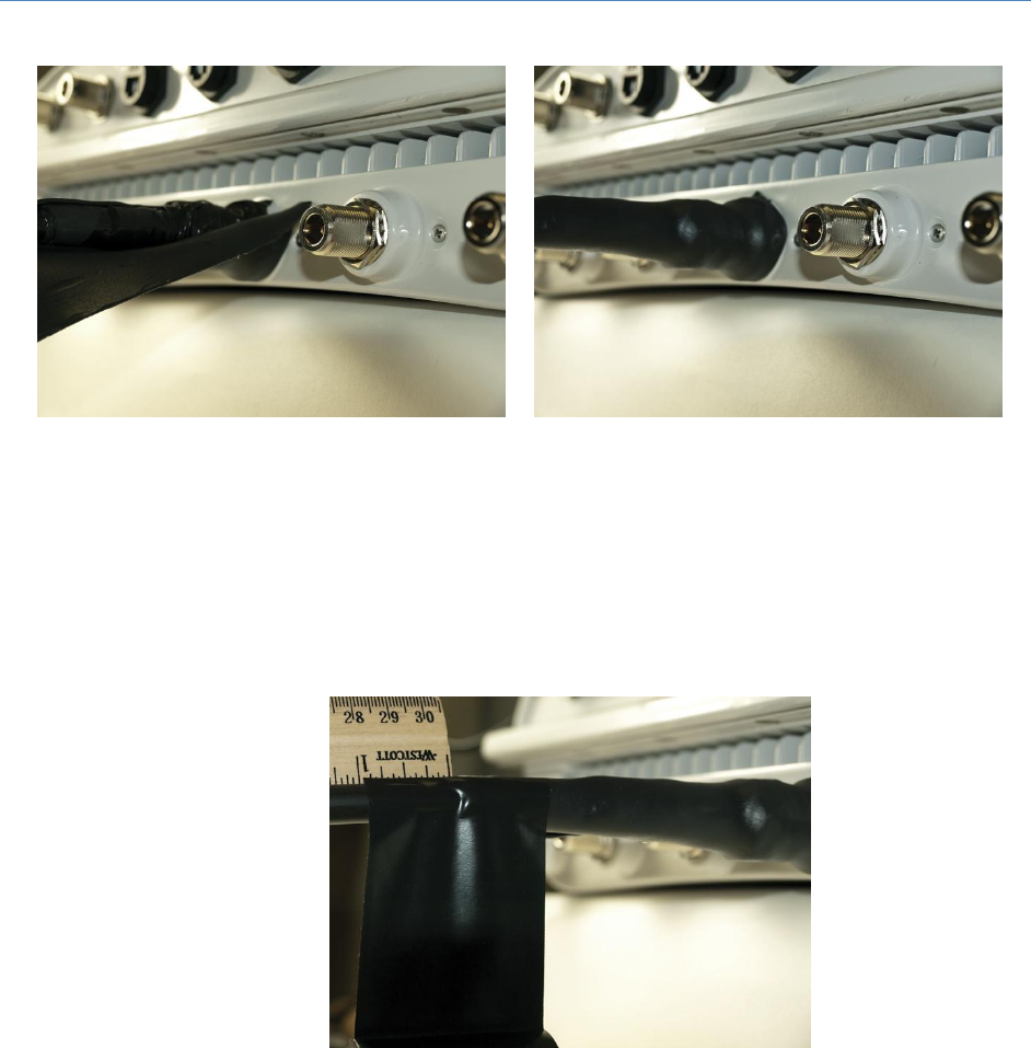
Quantum 2200 Installation Guide v2.1
Page 40
Figure 35: First Rubber Tape Layer
Step 4:
Start wrapping a layer of 2” (50-mm) plastic tape 1” (25 mm) below the rubber tape,
overlapping at half width (Figure 36). Finish the wrap at the flange of the antenna connector
and cut the tape.
Figure 36: Wrapping Plastic Tape on Top of the Rubber Tape
Step 5:
Start wrapping three layers of 3/4” (19-mm) plastic tape, 1” (25 mm) below the previous 2”
(50-mm) wrap, overlapping at half width (Figure 37) until the entire connector is wrapped.
The tape should be applied in one strip if possible. A strip can be coiled onto an applicator
such as a pencil. Apply only enough tension to get good adhesion and keep the tape smooth.
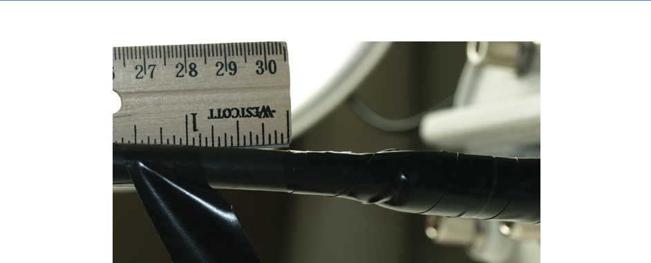
Quantum 2200 Installation Guide v2.1
Page 41
Figure 37: Wrapping ¾”Plastic Tape 1” Below Previous Wrap
Step 6:
Inspect your weatherproofing job for quality. Any exposed areas will quickly become
problematic. Repeat for all remaining connectors.

Quantum 2200 Installation Guide v2.1
Page 42
Appendix B Warranty Statements
Hardware
PureWave, Inc (“PureWave” or the “Company”) warrants to the end-user (“Customer”) that this
hardware product will conform in all material respects to the specifications provided with the hardware
and will be free from defects in workmanship and materials, under normal use and service, for a period
of 365 days from the date of original shipment by PureWave.
PureWave's sole obligation under this limited warranty shall be, at PureWave's option, to repair the
defective product or part, deliver to Customer an equivalent product or part to replace the defective
item, or if neither of the two foregoing options is reasonably possible, refund to Customer the purchase
price paid for the defective product. All products that are replaced will become the property of
PureWave. Replacement products may be new or reconditioned. PureWave's obligations hereunder
are conditioned upon the returned of affected articles in accordance with PureWave's Return Material
Authorization (RMA) procedures.
Subject to the limitations and conditions herein and in the Supply Agreement, after Customer has
completed the steps outlined below, PureWave will evaluate each returned Product and will use
reasonable commercial efforts to either, in its discretion, repair or replace products confirmed by
PureWave as non-conforming that are covered under the warranty provided in the Supply Agreement.
PureWave shall be responsible for shipping the repaired or replaced Product to Customer. PureWave
will use reasonable commercial efforts to ship repaired or replacement Product within thirty (30)
business days of its receipt, however, the allegedly non-conforming Product must be received by
PureWave before any replacement unit will be shipped.
The above warranty will also apply to any replaced or repaired product for 90 days from the date of
shipment from PureWave of the replaced or repaired product, or the remainder of the initial warranty
period, whichever is longer.
Software
PureWave warrants to the Customer that for a period of ninety (90) days from your receipt of the
Product (the “Warranty Period”) the Software will perform substantially in accordance with the
Documentation.
If the Software fails to comply with the warranty set forth above, your exclusive remedy will be, at the
option of PureWave (i) a reasonable effort by PureWave to make the Software perform substantially in
accordance with the Documentation, or (ii) return of the purchase price. This limited warranty applies
only if you return all copies of the Product, together with proof of purchase, to PureWave during the
Warranty Period.

Quantum 2200 Installation Guide v2.1
Page 43
This limited warranty is VOID if failure of the Software is due to modification of the Software not made
by PureWave, or the abuse or misapplication of the Software. PureWave does not warrant that the
Software is error free, that the Customer will be able to operate the Software without problems or
interruptions or that the Software or any equipment, system or network on which the Software is used
will be free of vulnerability to intrusion or attack.
Additional Conditions
Notwithstanding anything else herein or otherwise, PureWave reserves the right to establish
amendments to this RMA Policy from time to time. Further, PureWave Technical Support may prefer to
troubleshoot the wireless link with an onsite Customer technician while the Products are in their original
non-conforming state. This process might assist Customer in understanding and troubleshooting the
issue. If PureWave was not afforded the opportunity to troubleshoot an allegedly non-conforming
Product in original non-conforming state, PureWave may approve or reject the RMA request in its sole
discretion, and such Products are not eligible for advance replacement.
No Fault Found
Notwithstanding sections above, if PureWave cannot duplicate any alleged non-conformity, the Product
will be returned to the Customer as "No Fault Found." PureWave reserves the right to charge a testing
fee in connection with a returned product that PureWave determines as “No Fault Found,” and any such
payment must be received by PureWave prior to return shipment of the applicable Product to
Customer.
Warranty Limitations
PureWave’s warranties do not apply to any product (hardware or software) which has (a) been
subjected to abuse, misuse, neglect, accident, or mishandling, (b) been opened, repaired, modified, or
altered by anyone other than PureWave, (c) been used for or subjected to applications, environments,
or physical or electrical stress or conditions other than as intended and recommended by PureWave, (d)
been improperly stored, transported, installed, or used, or (e) had its serial number or other
identification markings altered or removed.
Warranty Disclaimer
PURWAVE’S SPECIFIC WARRANTIES SUMMARIZED ABOVE ARE THE ONLY WARRANTIES GIVEN BY
PUREWAVE WITH RESPECT TO ITS PRODUCTS (HARDWARE AND SOFTWARE) AND ARE GIVEN IN LIEU OF
ANY AND ALL OTHER WARRANTIES, WHETHER EXPRESS, IMPLIED, STATUTORY, OR ARISING BY CUSTOM,
TRADE USAGE, OR COURSE OF DEALING, INCLUDING WITHOUT LIMITATION ANY IMPLIED WARRANTIES
OF MERCHANTABILITY OR FITNESS FOR A PARTICULAR PURPOSE, AND PUREWAVE DISCLAIMS ANY AND
ALL OTHER WARRANTIES TO THE MAXIMUM EXTENT PERMITTED BY LAW. Without limiting the

Quantum 2200 Installation Guide v2.1
Page 44
generality of the foregoing sentence, PureWave makes no warranty or representation, either expressed
or implied, as to, and disclaims all liability and responsibility for, (a) the operation, compliance, labeling,
or packaging of any of its products under the laws of any jurisdiction outside of the United States of
America and (b) the regulatory compliance of any products in any jurisdiction in which it has not
specifically identified compliance or the use of any product in any jurisdiction in any manner other than
as contemplated in the regulatory certifications and approvals for that product in that jurisdiction. To
the extent an implied warranty cannot be excluded, such warranty is limited in duration to the warranty
period. The disclaimer and exclusion applies even if the express warranty fails of its essential purpose.
Obtaining Warranty Service
Customer must contact the Company, by sending an e-mail to support@pwnets.com to obtain warranty
service authorization. When contacting PureWave for support, please be prepared to provide the
product description and serial number and a description of the problem. The Customer will be expected
to complete a “Return Material Authorization (RMA)” form to initiate the request. Full instructions as to
how to complete and where to send the form are provided on the form. Date of proof of purchase from
PureWave will be required.
Products returned to PureWave Inc must be pre-authorized by PureWave with a Return Material
Authorization (RMA) number and sent prepaid and packaged appropriately for safe shipment. The
Customer requesting the RMA will be the exporter. The exporter is responsible to ship RMA equipment
to PureWave’s address and has to bear the cost and risk involved in bringing the goods to PureWave’s
location.
Risk of loss in return shipment will be borne by Customer, and it is recommended that returned goods
be insured and/or sent by a method that provides for tracking of the package. Responsibility for loss or
damage does not transfer to PureWave until the returned item is received by PureWave. Provided that
PureWave determines that the item is actually defective, the repaired or replaced item will be shipped
to Customer, at PureWave's expense, (1) not later than thirty (30) days after PureWave receives the
defective product or (2) to the terms of a separate written agreement with PureWave.
If the allegedly non-conforming Product is not received by PureWave within thirty (30) days of Customer
initiating the RMA request, the RMA process for that Product will be deemed cancelled.
Customer may also obtain the status of their RMA request(s) by sending an e-mail to
support@pwnets.com referencing their assigned RMA Number(s).
No product will be accepted for repair or replacement by PureWave without a RMA number. The
product must be returned to PureWave, properly packaged to prevent damage, shipping and handling
charges prepaid, with the RMA number prominently displayed on the outside of the container. If
PureWave determines that a returned product is not defective or is not covered by the terms of the
warranty, the Customer will be charged a service charge and return shipping charges.

Quantum 2200 Installation Guide v2.1
Page 45
Table 9 summarizes the conditions and charges that PureWave reserves the right to levy.
RMA Related Issue
Under Warranty
Repair and return
No charge, PureWave pays
Shipment of unit to PureWave
Customer pays
Regular Shipment to Customer
No charge, PureWave pays
Expedited shipment to Customer
Customer pays the additional cost of the expedited
shipping
No Fault Found
PureWave reserves the right to levy a charge
Warranty for repaired and or replaced product
Remainder of the original warranty or 90 days
Table 9: Summary of PureWave RMA Conditions and Charges
Out of Box Failure (OBF) / Dead on Arrival (DOA)
In the event a product becomes entirely inoperable within the first forty-eight (48) hours of the initial
installation of the product, and such installation takes place within ninety (90) days after the date of
shipment from PureWave, the Customer may request that the unit be considered as an “Out Box Failure
(OBF) or “Dead on Arrival (DOA).
PureWave will consider an OBF or DOA as being eligible to be considered for an advance replacement
request. The conditions for such a request are as outlined below.
Advanced Replacement
In some unique situations, PureWave may consider, at its sole discretion on a case-by-case basis, an
advance replacement request for a non-conforming Product that is still covered under its warranty
period.
The following conditions apply to advance replacements:
(i) PureWave has a suitable “equivalent” replacement unit available.
(ii) Customer’s network is experiencing a severe degradation or a complete outage.
(iii) Customer has complied with the RMA procedures provided herein
(iv) PureWave reserves the right to levy a charge for the processing and handling of the advance
replacement request. To waive this charge will be the sole discretion of the Senior VP of Sales.
(v) If expedited shipping is required then Customer pays for all expedited shipping and handling
charges that are in excess of the regular shipment charges. To waive this charge will be the sole
discretion of the Senior VP of Sales.

Quantum 2200 Installation Guide v2.1
Page 46
(vi) When an advance replacement is provided and Customer fails to return the original product to
PureWave within fifteen (15) days after shipment of the replacement, PureWave will charge the
Customer for the replacement product, at list price.
(vii) The shipment of advance replacement products is subject to local legal requirements and may
not be available in all locations.
PureWave will use reasonable commercial efforts to ship advance replacement Products within five (5)
business days after PureWave’s confirmation that advance replacement is appropriate. PureWave shall
not be responsible for shipping delays if any of conditions herein are not met.
For products that are out of warranty, the repair of such products will be subject to a repair fee. In
addition, any request for the Advance Replacement of product that is out of warranty will be subject to
not only the repair fee but additional fees as well. Please contact PureWave for further details.
PureWave does offer extended warranties and enhanced service options for its Customers who desire
those enhanced features. Please contact PureWave for further information about these options
Assistance
For assistance, contact your nearest PureWave Networks Sales and Service office.
Additional information is available on the PureWave Networks website at http://www.pwnets.com.
For Customer Service call: 650-528-5200, or Email: support@pwnets.com.
