Merrytek Technology MC603S Microwave Motion Sensor User Manual 2AI53 MC603S MC603S Manual
Shenzhen Merrytek Technology CO., LTD Microwave Motion Sensor 2AI53 MC603S MC603S Manual
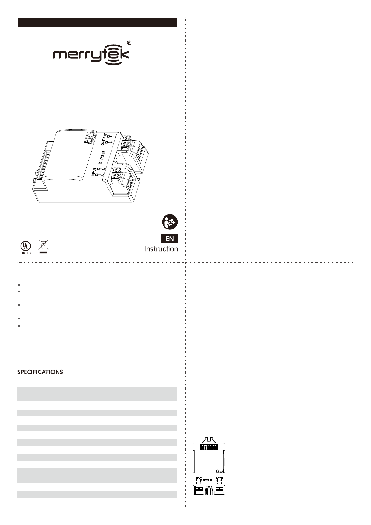
2AI53-MC603S_MC603S Manual
Model No.: MC603S
MC603S
GENERALGUIDELINESFORINSTALLATION
INSTALLATION & WIRING
The sensor has 7-position terminal block as Pic 1:
L(Phase) N(Neutral) L (Switched phase / control)
1-10V (Connected to 1-10V interface) Sync
(synchronization)
The sensor is designed for installation at 2.5-12m in height.
Pic 1
MICROWAVE MOTION SENSOR USER’S MANUAL
FEATURES
1, The sensor should be installed by a qualified electrician. And ensure
that the electricity supply is switched off before installing or servicing
the product.
2, The sensor should not be modified in any way. Any modifications
made for this product will immediately invalidate any warranties issued.
3, The company does not accept responsibility for any consequences
resulting from unauthorized modification of the product.
4, The sensor should be connected to a stable power supply of 220-
240Vac 50Hz/60Hz.
5, Microwaves cannot pass through metal or brick walls if thicker than
20cm. They will pass through thinner walls but there will be some
attenuation.
6, Installation inside a glass or plastic housing will result in a reduction of
detection sensitivity. Expect a reduction of approximately 20% for every
3mm of thickness.
C US
Automatic switching based on motion and light level.
Zero-crossing point operation helps protect the sensor against
in-rush current.
Super Compact size makes it suitable to fix within most
luminaires.
4-pole press-in terminal (L, N, N, L'), easy assembly.
Detection area, time delay and daylight threshold can be
precisely set via DIP switch.
Operating voltage 120/277Vac, 50/60Hz
Rated load 200W@120Vac 400W@277Vac-Ballast
400W@120Vac 800W@ 277Vac-Resistive
HF system 5.8GHz±75MHz, ISM wave band
Transmitting power <0.5mW
Power consumption ≤0.5W(standby)
Detection zone Max.(D x H): 10m x 6m
Detection sensitivity 10% / 50% / 75% / 100%
Hold time 5s / 30s / 90s / 3min / 20min / 30min
Daylight sensor 2lux / 10lux / 25lux / 50lux / Disable
Mounting height 6m Max.
Motion detection 0.5~3m/s
Detection angle 150°(wall installation)
360°(ceiling installation)
Operating temperature -25℃~60℃
IP rating IP20
FCC Warnning:
This equipment has been tested and found to comply with the limits for
a Class B digital device, pursuant to part 15 of the FCC Rules. These
limits are designed to provide reasonable protection against harmful
interference in a residential installation. This equipment generates, uses
and can radiate radio frequency energy and, if not installed and used in
accordance with the instructions, may cause harmful interference to
radio communications. However, there is no guarantee that
interference will not occur in a particular installation. If this equipment
does cause harmful interference to radio or television reception, which
can be determined by turning the equipment off and on, the user is
encouraged to try to correct the interference by one or more of the
following measures:
• Reorient or relocate the receiving antenna.
• Increase the separation between the equipment and receiver.
• Connect the equipment into an outlet on a circuit different from that
to which the receiver is connected.
• Consult the dealer or an experienced radio/TV technician for help.
Caution: Any changes or modifications to this device not explicitly
approved by manufacturer could void your authority to operate this
equipment.
This device complies with part 15 of the FCC Rules. Operation is subject
to the following two conditions: (1) This device may not cause harmful
interference, and (2) this device must accept any interference received,
including interference that may cause undesired operation.
This equipment complies with FCC radiation exposure limits set forth
for an uncontrolled environment. This equipment should be installed
and operated with minimum distance 20cm between the radiator &
your body.

Detection area, hold time and daylight sensor can be set by using DIP switches
on the sensor. Note that reducing the detection area will also reduce the sensitivity.
SETTINGS
1, Detection area
I: up to 100%
II: up to 75%
III: up to 50%
IV: up to 10%
2, Hold time
Refers to the time period the lamp remains at
100% illumination after no motion is detected.
I: 5s
II: 30s
III: 90s
IV: 3min
V: 20min
VI:30min
When set to 30min,The sensor function will be inactive,
the light will go back to normal one.
3,Daylight sensor
The sensor can be set to only allow the lamp to
illuminate below a defined ambient brightness
threshold. The settings are as follows:
I: 2lux, darkness operation only
II: 10lux, darkness operation only
III: 25lux, twilight operation
IV: 50lux, twilight operation
V: Disable
*When set to Disable, the daylight sensor will switch on the lamp when motion
is detected regardless of ambient light levels.
*It should be set to Disable mode if the motion sensor is connected to
stand-alone daylight sensors.
Shenzhen Merrytek Technology Co..Ltd
No.3 Building, 380 Xiangshan Avenue, No.3 Industrial Park Luotian, Songgang Town, Bao’an District, Shenzhen 518105, Guangdong, China
www.merrytek.com Email:sales@merrytek.com
ON ON
ON
ON
ON Ⅰ
Ⅱ
Ⅲ
Ⅳ
1 2
100%
75%
50%
10%
ON ON ON
ON ON
ON ON
ON
ON ON
ON
Ⅰ
Ⅱ
Ⅲ
Ⅳ
Ⅴ
3 4 5
Ⅳ
5s
30s
90s
3min
20min
30min
ON ON ON
ON ON
ON
ON
ON Ⅰ
Ⅱ
6 7 8
Disable
50lux
10lux
2lux
25lux
Ⅲ
Ⅳ
Ⅴ
FOR ON/OFF FUNCTION :
Connect to normal control gears (normal LED drivers or ballasts), the wiring as
following:
WIRING SCHEME
LN
L
LL
N
NN
Control gear
Max. 400W
L
LL
L
LL
N
NN
N
NN
Control gear Control gear
DETECTION PATTERN
10%
50%
75%
100%
0
2
4
8
6
2
4
6
8
10 1 2 14
10
12
14
10
12
14
10%
50%
75%
100%
1 2 3 4 55 4 3 2 1
Ceiling mounting pattern (Unit: m)
Suggested installation height: 2.5-6m
Wall mounting pattern (Unit: m)
Suggested installation height: 1-1.8m
Question
The load will
not illuminate
Incorrect daylight
sensor setting selected.
Load has failed.
Power is switched off. Switch on.
Adjust setting.
Replace load.
Continuous movement in the
detection area.
The lamp (containing sensor) is
installed in an area too close to
reflective surfaces, i.e. metal,
glass or concrete walls.
Check detection area setting.
1, Make sure installation area
suitable with at least 30cm space
between lamp and surrounding
reflective surfaces.
2, Reduce sensitivity (detection area).
The load is
permanently
illuminated.
The load will
not illuminate
despite
movement.
Speed of moving object is not in
the range of 0.5-3m/s or the
detection radius is too small.
Check detection area setting.
Cause Remedy
FAQ
ON
Const-
ant ON
When set to “Const-ant ON”, the microwave
sensor function is inactive, lights turns on or
off by switch.
When set to Sensor, the microwave sensor
function is active.
4,Stand-by dimming level