Mertik Maxitrol and KG G6RH Handset of remote electronic ignition and control system for gas applications User Manual GV60 B II OI EN FR 09 2014 Manual
Mertik Maxitrol GmbH & Co. KG Handset of remote electronic ignition and control system for gas applications GV60 B II OI EN FR 09 2014 Manual
User Manual
GV60
Remote Electronic Ignition and Control System
Exclusive Distributor for Maxitrol Company
Precision Engineering for Multiple Markets
ENGLISH – INSTALLATION AND OPERATING INSTRUCTIONS .......................................................................... 2
DEUTSCH – INSTALLATIONS- UND BEDIENUNGSANLEITUNG ..................................................................... 22
FRANCAIS – INSTRUCTIONS D’INSTALLAT ION ET DE SERVICE ...............................................................42
NEDERLANDS – INSTALLAT IEHANDLEIDING EN BEDIENINGSHANDLEIDING ...............................64
0085

2 / 84
© 2014 Mertik Maxitrol GmbH & Co. KG, All Rights Reserved.
ENGLISH
CONTENTS
IMPORTANT SAFETY INFORMATION ............................................3
NEW GV60 HANDSET DESIGN ......................................................3
INSTALLATION INSTRUCTIONS
Application ................................................................................. 4
Components .............................................................................. 4
Technical Specifications ............................................................ 5
Gas Connections ....................................................................... 6
Perform Gas Leak Test .............................................................. 7
Wiring Connections ................................................................... 7
Gas Control Knob Settings ...................................................... 13
Adjustment .............................................................................. 13
Final Check ............................................................................. 14
OPERATING INSTRUCTIONS
General Notes ......................................................................... 15
Setting the Electronic Code ..................................................... 15
To turn ON Appliance .............................................................. 16
To turn OFF Appliance ............................................................ 16
Flame Height Adjustment ........................................................ 16
To open and close Solenoid Valve/Burner ............................... 17
Light/Dimmer Operation .......................................................... 17
Circulating Fan Operation ....................................................... 17
Modes of Operation ................................................................. 17
Setting °C/24 Hour or °F/12 Hour Clock ...................................18
Setting the Time ...................................................................... 18
Setting the ON/OFF Temperatures .......................................... 18
Setting Program Timers .......................................................... 19
Manual Operation .................................................................... 19
Turn OFF Gas to Appliance ..................................................... 20
Automatic Turn Down .............................................................. 20
Automatic Shut Off .................................................................. 20
3 / 84
© 2014 Mertik Maxitrol GmbH & Co. KG, All Rights Reserved.
ENGLISH
damage, personal injury, or loss of life. The product must be installed and operated according to all codes and local regulations.
Damper position must be in accordance with Manufacturer’s Installation Instructions and all applicable Standards. Failure to
follow these Instructions and/ or Standards may cause property damage, personal injury, or loss of life.
Do NOT
WHAT TO DO IF YOU SMELL GAS
NOT operate any appliance.
NOT touch any electrical switch; do NOT use any phone in your building.
with local codes, or in the absence of local codes, in accordance with the National Fuel Gas Code ANSI Z223.1/NFPA 54 or the
IFGC or CSA B149.1. All piping and tubing must comply with local codes and ordinances.
Do NOT-
ELECTRIC SHOCK HAZARD
must be performed by a trained, experienced service technician.
DO NOT use the control if you suspect it may be damaged.
IMPORTANT SAFETY INFORMATION
NOTICE
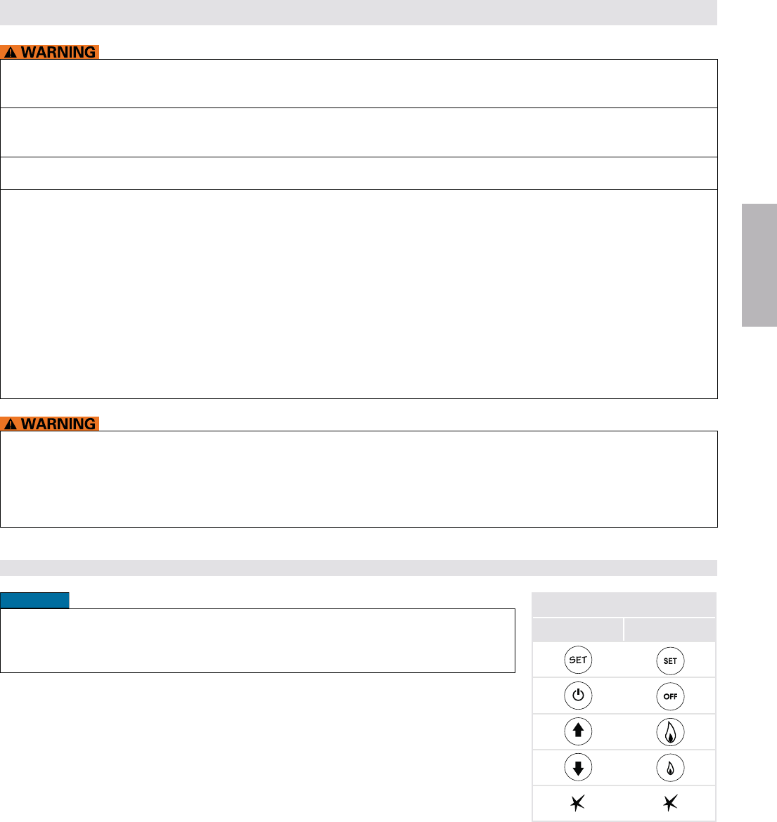
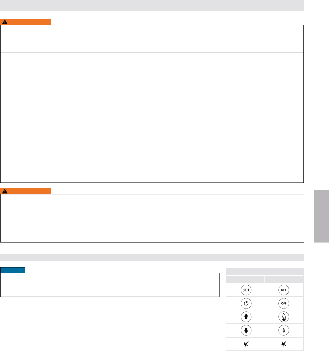
The redesigned GV60 handsets G6R-H...FB and G6R-H...FW operate exactly the same as
the previous handset G6R-H... Only the symbols on the buttons have been changed (see
“KEY ASSIGNMENTS” for corresponding symbols).
KEY ASSIGNMENTS
G6R-H...FB(W) G6R-H...
=
=
=
=
=
NEW GV60 HANDSET DESIGN (2012)
4 / 84
© 2014 Mertik Maxitrol GmbH & Co. KG, All Rights Reserved.
ENGLISH
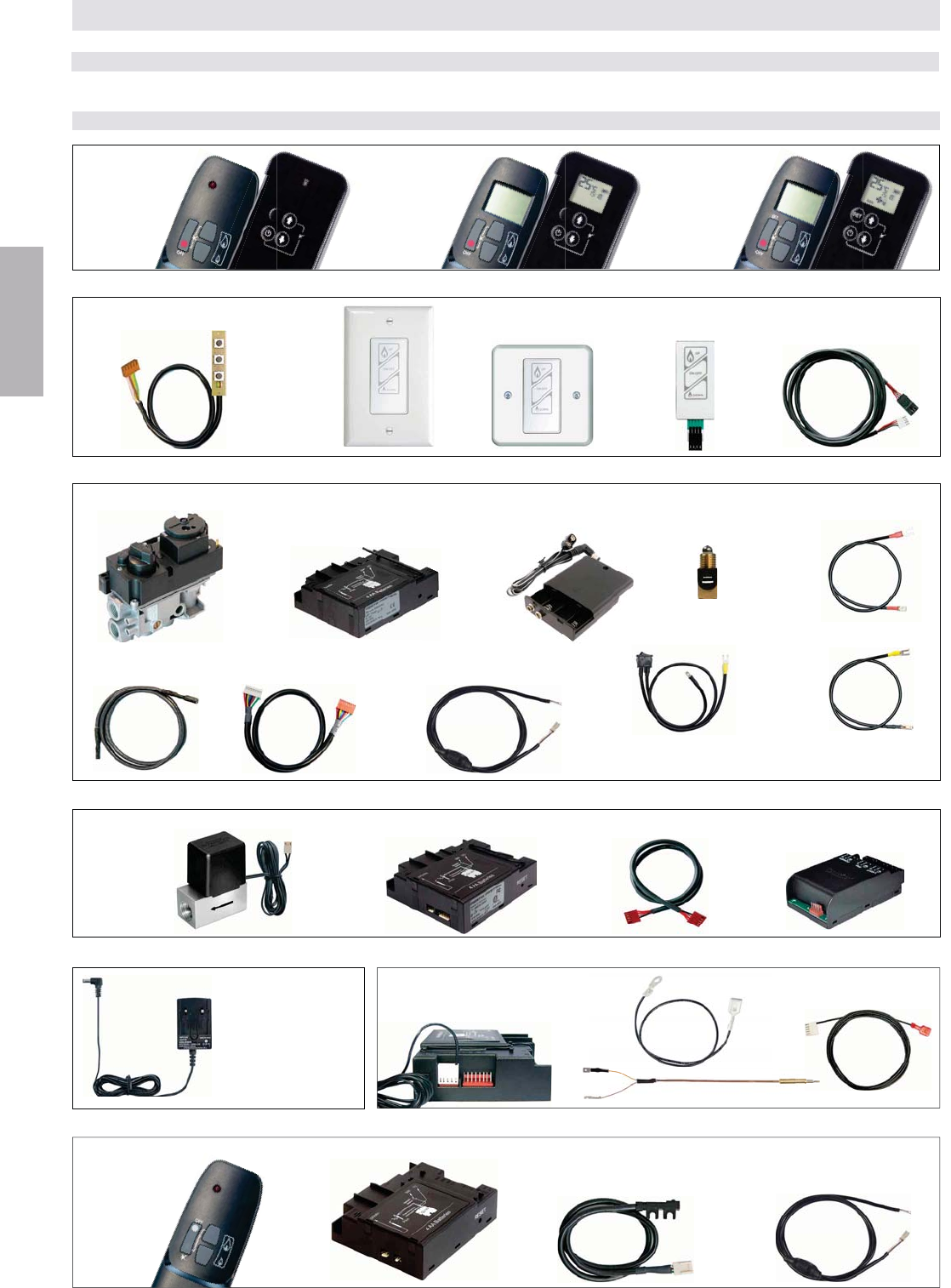
G60-ZMA3 with
connections for
EU, UK, and U.S.
Figure 4: Additional Function RF: FAN – Light/Dimmer – Latching Solenoid
INSTALLATION INSTRUCTIONS FOR OEM USE ONLY
Figure 2: Operation
Switch Panel
with cable
G6R-SPN-...
Wall Switch US
G6R-ZWSN..-... Wall Switch EU
G6R-ZWSE-...
Touchpad
G6R-TPN-...
Cable Wall Switch/Touchpad
G6R-CWSN-...
Figure 3: Basic RF
Standard Receiver
G6R-R3(4)AM...
Ignition Cable
G60-ZKIS...
8 Wire Cable GV-Receiver
G6R-C...
Interrupter Block
G60-ZUS...
Thermocurrent Cable
Interrupter-Receiver TC
G60-ZKIRSS/...
Combination Control
GV60
Thermocurrent Cable Interrupter-Receiver SW
without ON/OFF switch
G60-ZKIRSWS/...
or
Universal Receiver
G6R-R3(4)AU...
Cable with Relay
G6R-CD..., G6R-CDB (optional)
or
The
r
Battery Box
G60-ZB90/...
with ON/OFF switch
G60-ZSKSS/..., G60-ZSKLS/...
Latching Solenoid Valve
(with cable)
GV-S60
Cable V Module-Receiver
G6R-CBV...
V Module
G6R-BU..., G6R-BE...
Receiver
G6R-R3(4)AU...
Figure 6: RF 2nd Thermocouple Option
Figure 5: Mains Adapter
Receiver
G6R-R3(4)AUT
2nd Thermocouple Cable
G60-ZCTC...
Ground Cable
G60-ZCGTC/…
d
C
able
CG
T
C/
…
Cable with Relay
G6R-CL... (optional)
Infrared Handset
G6R-HIO…
(FB(W))
Infrared Sensor
G6R-IRC
Receiver
G6R-RIAE
Figure 7: Infrared (IR)
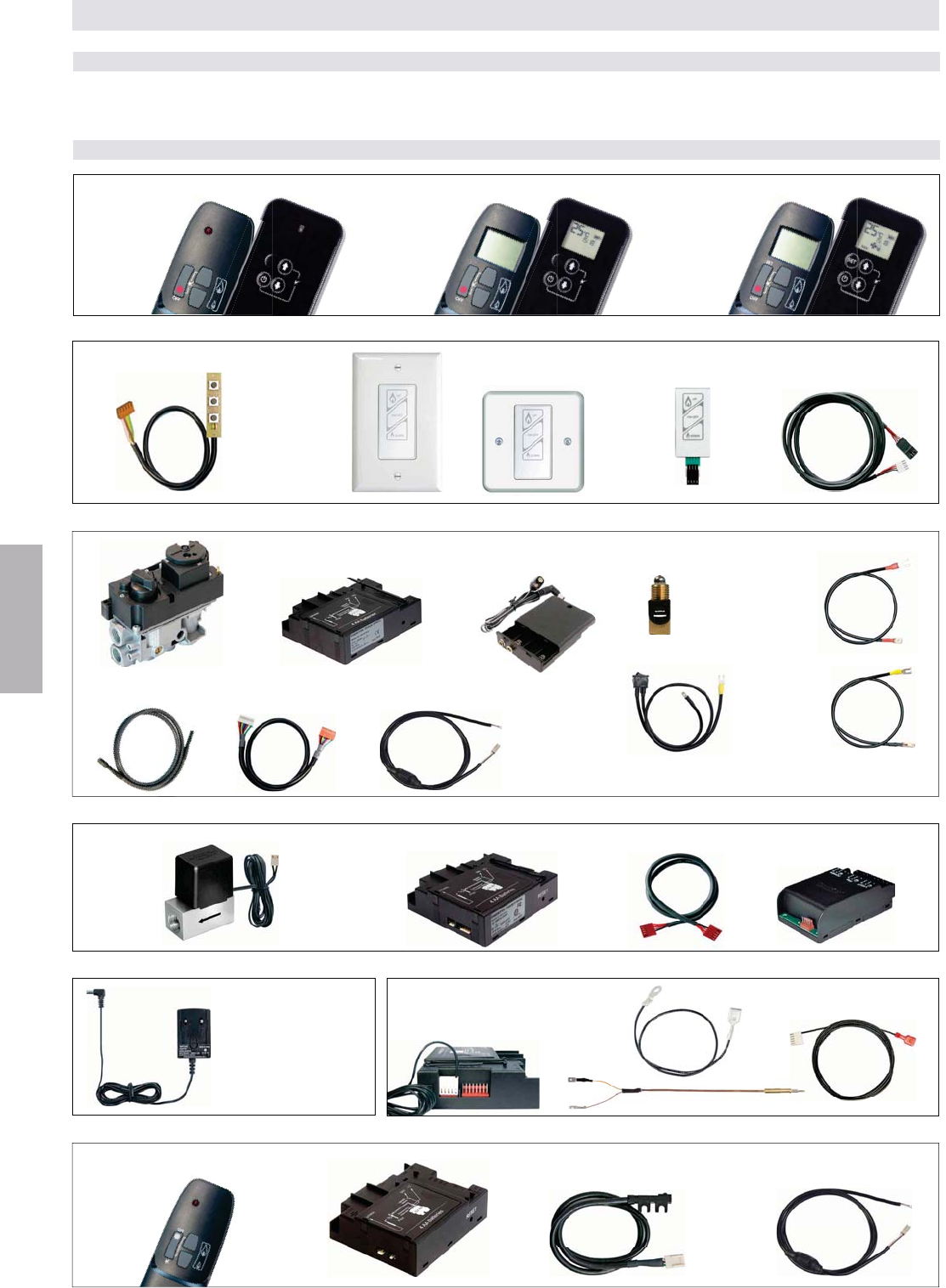
APPLICATION
GV60 is a battery-powered electronic remote ignition and control system for gas appliances with pilot burners and ODS systems.
Standard RF Handset
G6R-H3S...(FB(W))
G6R-H4S...(FB(W))
Display RF Handset
G6R-H3D...(FB(W))
G6R-H4D...(FB(W))
Timer/Thermostat RF
Handset
G6R-H3T...(FB(W))
G6R-H4T...(FB(W))
H
Figure 1: Remotes, on the right side each the redesigned models
COMPONENTS
2nd Thermocouple G60-ZPT…

5 / 84
© 2014 Mertik Maxitrol GmbH & Co. KG, All Rights Reserved.
ENGLISH
Receiver infrared with/without batteries: 131 °F (55°C)
Handset: 140 °F (60 °C)
Wall switch/Touchpad: 176 °F (80 °C)
Switch panel: 221 °F (105 °C)
Module: 176 °F (80 °C)
Ignition cable: 302 °F (150 °C)
Misc. cables: 221 °F (105 °C)
Infrared sensor: 176 °F (80 °C)
Cable with relay: 158 °F (70 °C)
HANDSETS
NOTICE
The handsets, receivers, wall switches, switch panels
and touchpads are not interchangeable with previous
electronics.
RADIO FREQUENCY
CSA: 315 MHz for U.S. and for Canada.
For FCC ID:
a) User Information acc. to FCC15.21: Changes or
responsible for compliance could void the user’s
For Canada - IC:
Statement acc. RSS Gen Issue 3, Sect. 7.1.3
This device complies with Part 15 of the FCC Rules
and with Industry Canada license-exempt RSS
standard(s). Operation is subject to the following two
conditions: (1) this device may not cause harmful in-
terference, and (2) this device must accept any in-
terference received, including interference that may
cause undesired operation.
CE: 433.92 MHz for Europe
BATTERIES – HANDSET
1 x 9 V, new design 2012: 3 x 1,5 V „AAA“
(alkaline recommended)
BATTERIES – RECEIVER
4 x 1.5 V “AA” (alkaline recommended)
An AC Mains Adapter may be used instead of batteries.
NOTICE
Only the Mertik Maxitrol AC Mains Adapter or one pre-
approved by Mertik Maxitrol can be used. Use of other
adaptors can render the system inoperable.
V MODULE
CSA: Inlet: 115 VAC/60 Hz; 210 VA
Outlet: 115 VAC/60 Hz; 100 VA
Built-in fuse: 2.5 A
CE: Inlet: 230 VAC/50 Hz; 210 VA
Outlet: 230 VAC/50 Hz; 100 VA
Built-in fuse 2,5 A
LOCATION
Locate the combination gas valve where it is not exposed
to steam cleaning, high humidity, dripping water, corrosive
chemicals, dust or grease accumulation, or excessive heat.
To assure proper operation, follow these guidelines:
INSTALLATION INSTRUCTIONS FOR OEM USE ONLY
TECHNICAL SPECIFICATIONS
Gas combination control according to CSA or CE ap-
FUELS
CSA: Suitable for natural, manufactured, mixed gases,
CE: Suitable for use with gases of EN 437 gas family 1,
2 and 3.
APPROVALS
CSA: ANSI Z21.78/CSA 6.20 for U.S. & Canada,
ANSI Z21.20/CSA 6.20 for U.S. & Canada
CE: Gas Appliances Directive 2009/142/EG and EN
298-2003, DIN EN 126
Infrared Handset: GADAC Guidance Sheet B12
PRESSURE DROP/CAPACITY
CSA: 1” W.C. at 65,000 BTU/hr
CE: 2.5 mbar at 1.2 m³/h air
RANGE OF REGULATION
CSA: 10,000 to 85,000 BTU/hr
CE: Class C according EN 88
REGULATOR ADJUSTMENT
CSA: 3” W.C. to 5” W.C. (7.5 to 12.5 mbar); 8” W.C. to 12”
W.C. (20 to 30 mbar)
CE: 5 to 40 mbar
CE+CSA: 3” W.C. to 12” W.C. (7.5 to 30 mbar)
Convertible Regulator: 3 to 4.5” NG/8.5 to 11.5” LP
MOUNTING POSITION
Mount valve 0° to 90°, in any direction (including vertically)
from the upright position of the gas control knob.
MAXIMUM INLET PRESSURE
CSA: ½ psi (34.5 mbar)
CE: 50 mbar (20” W.C.)
MAIN GAS CONNECTION
10 mm, 8 mm, 6 mm outside diameter tube.
8 mm, 6 mm outside diameter tube.
INLET AND OUTLET CONNECTION
Side or Bottom
MAXIMUM ALLOWED TORQUE INLET AND OUTLET
CSA: 280 inch-pounds
CE: 35 Nm
PILOT GAS CONNECTION
CE: M10x1 for 4 mm or 6 mm tubing
THERMOCOUPLE/INTERRUPTER BLOCK
11/32-32 UNS, M10x1, M9x1, M8x1
AMBIENT TEMPERATURE RANGE
Combination control: 32 °F to 176 °F (0 °C to 80 °C)
Latching solenoid valve: 32 °F to 176 °F (0 °C to 80 °C)
Receiver RF without batteries: 176 °F (80 °C)
Receiver RF with batteries: 131 °F (55°C)
16
6 / 84
© 2014 Mertik Maxitrol GmbH & Co. KG, All Rights Reserved.
ENGLISH
Connection Main Gas
(Pipe Connections)
1. Do NOT®/PTFE tape.
2. Pipe to be inserted into the valve must be the proper
thread length and to gauge. Thread that is cut too long can
cause distortion or malfunction if inserted too deeply.
3. Apply a moderate amount of approved pipe sealant to the
pipe only, leaving the two end threads bare.
4. Connect pipe to valve inlet and outlet.
Connection Pilot Gas (Tubing connections)
1. Do NOT®/PTFE tape.
2. Slip one-piece(
nut
with ferrule/olive) over tubing.
3. Insert pilot tubing into pilot outlet until it bottoms. Turn
4. Turn with a wrench until you shear off the ferrule/olive from
the nut. Turn an additional ¾ turn to make a gastight seal.
5. Connect other end of tubing to pilot burner.
The main gas valve must be disconnected from the gas
supply piping system during any pressure testing of the gas
supply piping system at test pressures in excess of ½ psi
(3.5 kPa CSA; 50 mbar CE). Overpressurizing can dam-
age the control resulting in leakage or control malfunction.
-
ambient temperature ratings for each component.
GV60 standard version is suitable for indoor use only.
It is the appliance manufacturer’s responsibility to deter-
Do NOT remove screws from the gas valve. Do NOT adjust
and/or alter any components marked with tamper indicating
paint. Motor knob is not to be removed.
1. Turn off gas supply at the appliance service valve before
starting installation, and perform a Gas Leak Test after
the installation is complete.
supply line to prevent contamination of the gas valve
3. Use only your hand to push in or turn the gas control
knobs. Never use tools. If a knob will not push in or turn
by hand, do NOT
technician. Force or attempted repair will void warranty
GAS CONNECTIONS
Fire or Explosion Hazard. Can cause property dam-
age, severe injury, or death. Do NOT bend tubing at gas
tightened. This can result in gas leakage at the connection.
Use new, properly reamed pipe free from metal or material
deburred and clean. All tubing bends must be smooth and
free of distortion.
Do NOT overtighten connections. Overtightening can damage
the control body resulting in leakage or control malfunction.
When threads are tightened, the valve must be held at the
NOT apply
pressure to top casting or plastic cover.
Connection Main Gas (Tubing connections)
1. Do NOT®/PTFE tape.
2. Slip nut and ferrule/olive over tubing.
3. Slide nut and ferrule/olive into place, and insert tubing into
INSTALLATION INSTRUCTIONS FOR OEM USE ONLY
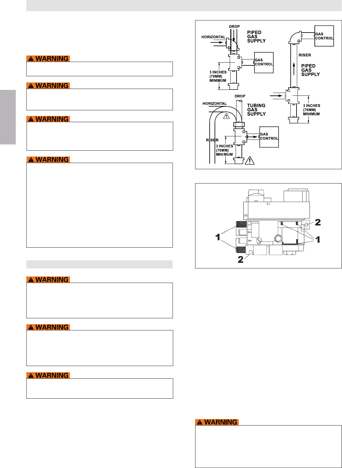
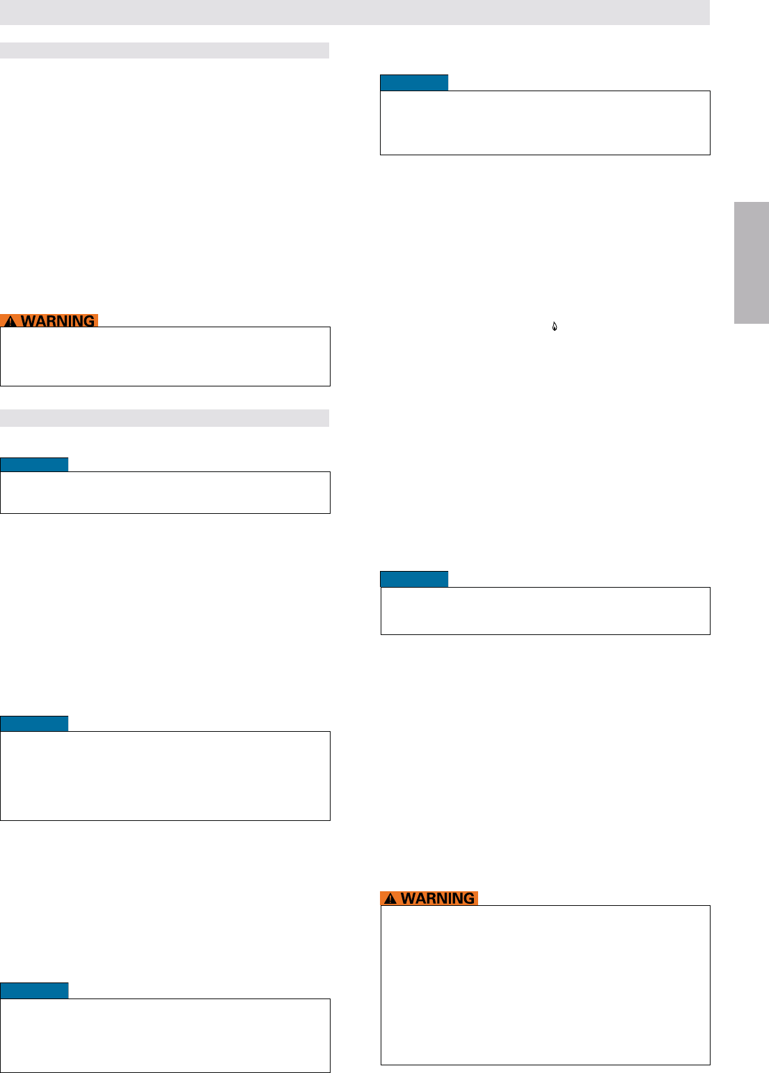
Figure 9: 1 = Clamping Areas, 2 = Mounting Points
Sediment Trap
Sediment Trap
Sediment Trap
Figure 8: Sediment Trap (where required)
7 / 84
© 2014 Mertik Maxitrol GmbH & Co. KG, All Rights Reserved.
ENGLISH
Receiver
NOTICE
To keep the receiver free from debris, dirt, and humidity,
do NOT remove the receiver from the plastic bag until all
construction is complete.
1. Insert batteries or connect AC mains power. The mod-
ule for circulating fan and light/dimmer includes a mains
adapter. With mains adapter, batteries can be used for
backup (RF only).
ON position.
3. The receiver has to learn the handset code:
page 8) until you hear two (2) beeps. After the second,
longer beep, release the reset button. Within the subse-
code is set.
NOTE:
when changing the batteries in the handset or re-
ceiver.
4. Check the reception. For better reception straighten the
antenna and move it to a position
that allows for better reception (see notice below).
5. When the RF-receiver is placed in the appliance, the sur-
rounding metal can reduce reception considerably. The
reception.
NOTICE
The antenna must not cross or come into contact with
the ignition wire. This will render the receiver inoperable.
IR Versions
Place the infrared eye in a suitable position. The infrared
V Module
-
wires with core cable ends to the pluggable screw terminals.
2-
ure 11, page 9).
supply.
ELECTRIC SHOCK HAZARD
could result in property damage, personal injury, or loss
of life.
accordance with all codes and local regulations. Service
and installation must be performed by a trained, experi-
enced service technician.
NOT use the module if you suspect it may be damaged.
PERFORM GAS LEAK TEST
1. Check carefully for gas leaks immediately after the valve
has been installed and the gas turned on. Do this be-
fore attempting to operate the appliance or other gas
burning device.
2. Use an approved -
er approved leak detection method, around the diaphragm
Bubbles indicate a leak.
3. If no leakage is detected, light the main burner.
4. With the main burner in operation, apply an approved leak test
solution to all tubing and pipe connections (including adapt-
ers) and the valve inlet and outlet. Bubbles indicate a leak.
5. If a leak is detected, tighten pipe connections (including
adapters) according to “GAS CONNECTIONS” (page 6).
Absolutely no leakage should occur, otherwise there is a
Never use if leakage is detected.
WIRING CONNECTIONS
NOTICE
Wiring of valve and receiver must be completed before start-
ing ignition. Failure to do so could damage the electronics.
-
ing diagram.
not exposed to dirt, oil, grease or other chemical agents.
NOT permit foreign particles under plastic cover.
-
cessible for the user.
Thermocouple Circuit
Total resistance of thermocouple circuit should be minimized
to ensure proper operation.
NOTICE
The use of the Mertik Maxitrol interrupter block is rec-
ommended. Keep connection of interrupter block and
thermocouple clean and dry. Avoid severe bending of the
thermocouple tubing during installation (min. 1” radius;
2.5 cm) as this may cause it to fail.
tight (2...3 Nm).
(2...3 Nm).
Ignition Cable
Do NOT damage the ignition cable while attaching it to the
ignition electrode. When the cable is in place, avoid contact
with sharp objects or edges. With cables longer than 900 mm,
avoid contact with metal parts, as this could decrease spark.
NOTICE
INSTALLATION INSTRUCTIONS FOR OEM USE ONLY
8 / 84
© 2014 Mertik Maxitrol GmbH & Co. KG, All Rights Reserved.
ENGLISH
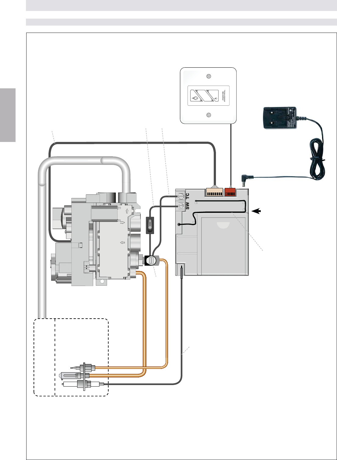
BASIC (RF)
INSTALLATION INSTRUCTIONS FOR OEM USE ONLY
ON-OFF
UP
DOWN
Figure 10
Pilot Burner
Wall Switch
(optional)
Thermocurrent Cable SW
with ON/OFF Switch
Thermocurrent Cable TC
8 Wire Cable
Interrupter Block
Mains Adapter
(optional)
Ignition Cable
RESET Button
GV60 Valve
W
all
S
w
i
tc
h
(
optional
)
M
ai
a
a
(
op
t
n
Main Burner
Receiver
G6R-R3(4)AM...
or
G6R-R3(4)AU...
Antenna
9 / 84
© 2014 Mertik Maxitrol GmbH & Co. KG, All Rights Reserved.
ENGLISH
12
12 12 12
12 12
12 12 12
12 12 12
12 1212
12 12 12
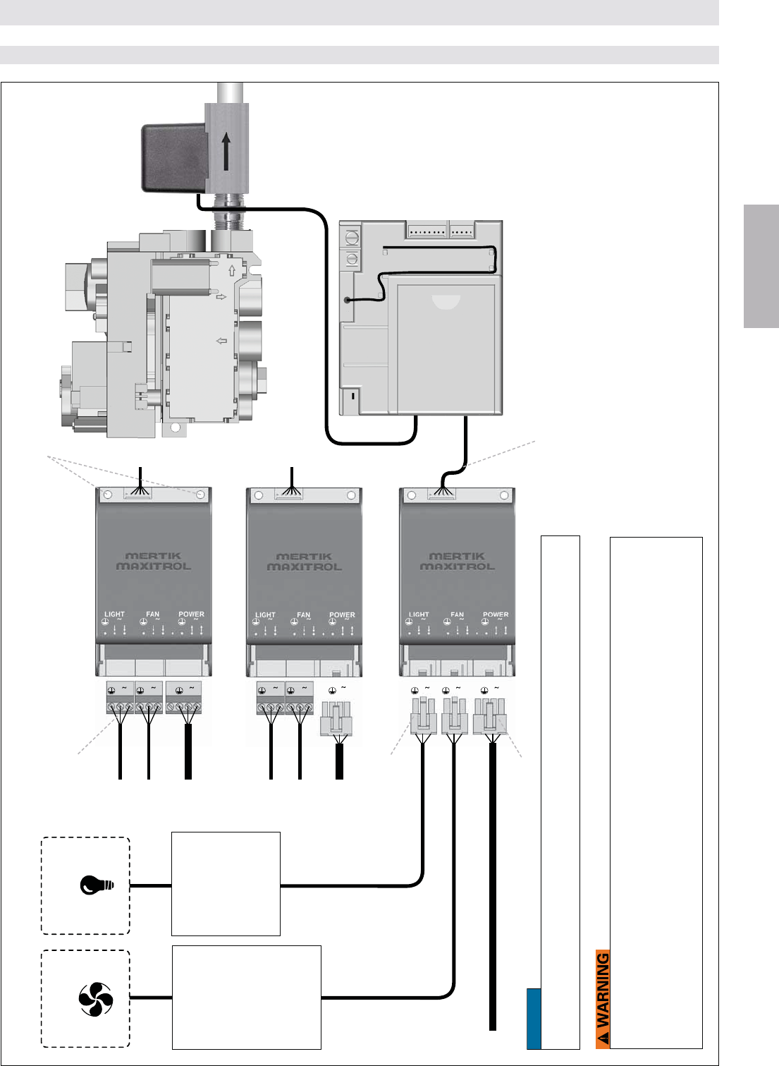
Figure 11
ADDITIONAL FUNCTION RF: FAN – LIGHT/DIMMER – LATCHING SOLENOID
INSTALLATION INSTRUCTIONS FOR OEM USE ONLY
Receiver
G6R-R3(4)AU...
G6R-BU(E)AV2
G6R-BU(E)SV2
G6R-BU(E)MV2
NOTICE
Hand tighten M4 screws (not provided) to secure the module via the two pre-drilled screw holes. Use
only M4 screws to secure the module.
Max. AWG 12/2.5 mm2
GV60 Valve
ELECTRIC SHOCK HAZARD
injury, or loss of life.
-
tions. Service and installation must be performed by a trained, experienced service technician.
NOT use the module if you suspect it may be damaged.
4 levels from
60 % to 100 %
14 to 100 Watt
The appliance
manufacturer must
test levels with fan.
Levels may vary
with fan
characteristics.
20 % to 100 %
14 to 100 Watt
Not for LED and
not for energy
saving lamp. Latching Solenoid
Valve
Latching solenoid
as shown shuts off
burner 2, leaving
burner 1 on.
For other options con-
sult Mertik Maxitrol.
Cable V Module-Receiver
Molex 39-01-4031
Molex 39-01-4041
Screw holes for use with M4 screws
(not provided)
10 / 84
© 2014 Mertik Maxitrol GmbH & Co. KG, All Rights Reserved.
ENGLISH
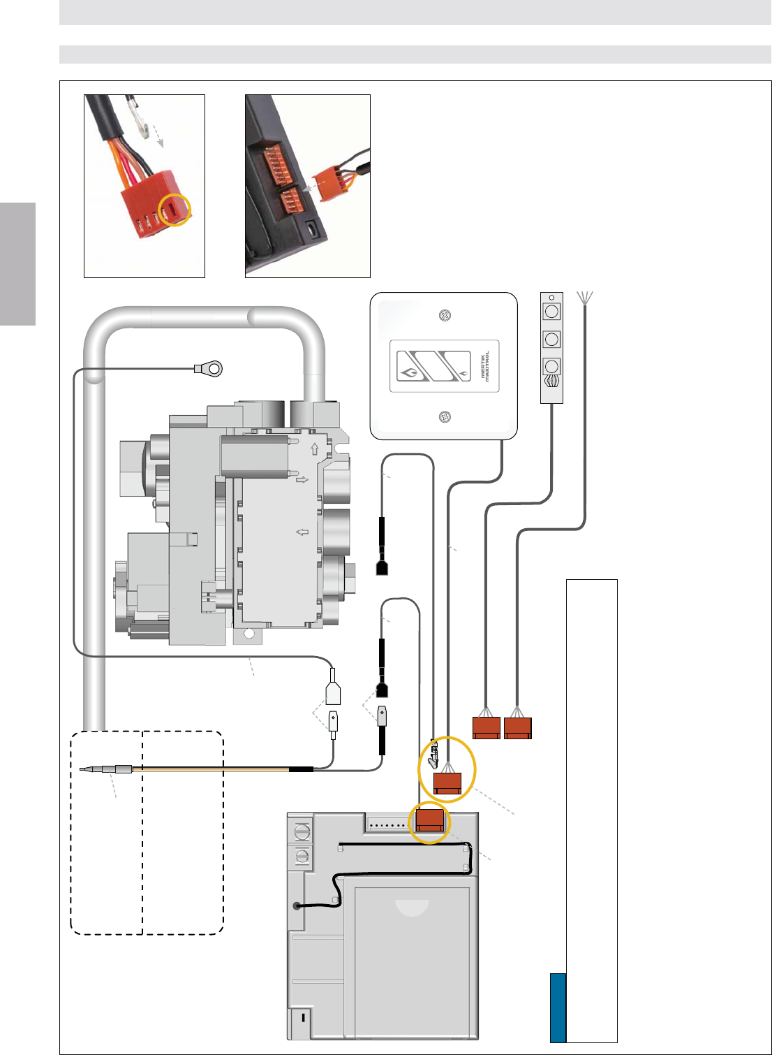
Figure 12
RF 2ND THERMOCOUPLE OPTION (RF)
INSTALLATION INSTRUCTIONS FOR OEM USE ONLY
ON-OFF
UP
DOWN
nd thermocouple is placed in the main burner to check that the main gas is ignited within
a certain time after opening.
opening main gas.
nd
operate without the thermocouple connected. Other versions will not operate if the thermo-
couple is connected.
ZCTCR/2000 is needed.
Combination with Wall Switch
1. Remove G60-ZCTC/2000 cable and replace with Wall Switch/Touchpad G6R-CWSN… cable.
2. Insert the MOLEX crimp terminal of the G60-ZCTCR… cable into the open connector hole
of the plug (see image 1). Listen for a “click”.
3. Insert the insulated receptacle into the insulated 2nd thermocouple terminal.
4. Insert the plug connector into the receiver (see image 2).
2nd thermocouple
G60-ZPT300
2nd Thermocouple cable
G60-ZCTC… 2nd Thermocouple cable
G60-ZCTCR…
Cable connection for
combination with Wall Switch
Standard connection
Ground cable
G60-ZCGTC/…
Wall Switch (optional)
Image 1: Lock MOLEX crimp terminal (G60-
ZCTCR…) inside connector hole of the plug.
Image 2: Insert plug connector into the receiver.
Switch Panel (optional)
External Operation (optional)
GV60 Valve
Insulated cable
Non-insulated
cable
Wall Switch/Touchpad cable
G6R-CWSN…
NOTICE
To install the 2nd thermocouple make sure that the insulated male spade is connected to the
insulated female spade. The non-insulated male spade must be connected to the female spade
ground cable. The ground cable should be connected to the ground at the valve or the heater.
Receiver
G6R-R3(4)AU..T
Main Burner
Pilot Burner
(not shown here)
11 / 84
© 2014 Mertik Maxitrol GmbH & Co. KG, All Rights Reserved.
ENGLISH
ON-OFF
UP
DOWN
Figure 13
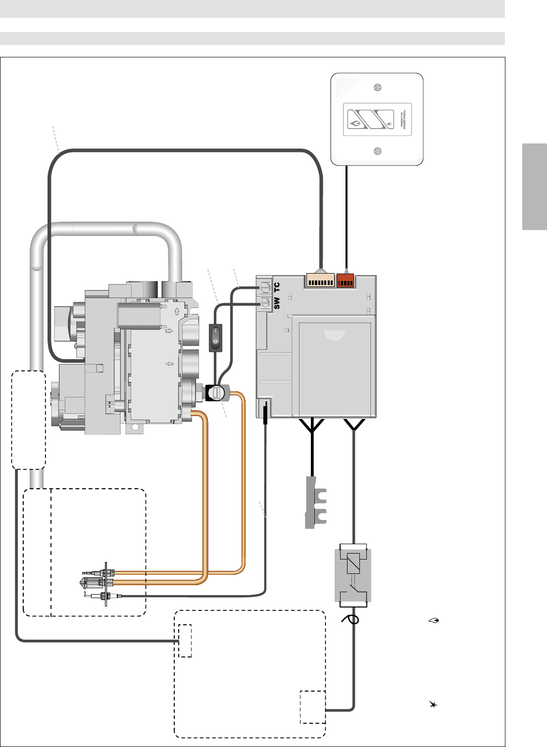
(star) button and the
once the exhaust control establishes a positive draft, the solenoid valve will open supplying main gas to the burner.
-
ditional switch should be added to the system to turn off the fan.
START
IN
Infrared Sensor
Wall Switch
(optional)
Power Flue Control
(optional)
Receiver
G6R-RIAE
8 Wire Cable
Interrupter Block
Ignition Cable
INFRARED (IR)
INSTALLATION INSTRUCTIONS FOR OEM USE ONLY
Relay with Cable
G6R-CL... (optional)
GV60 Valve
Pilot Burner
Main Burner
Solenoid Valve
Flue Control)
Thermocurrent Cable SW
with ON/OFF Switch
Thermocurrent Cable TC
12 / 84
© 2014 Mertik Maxitrol GmbH & Co. KG, All Rights Reserved.
ENGLISH
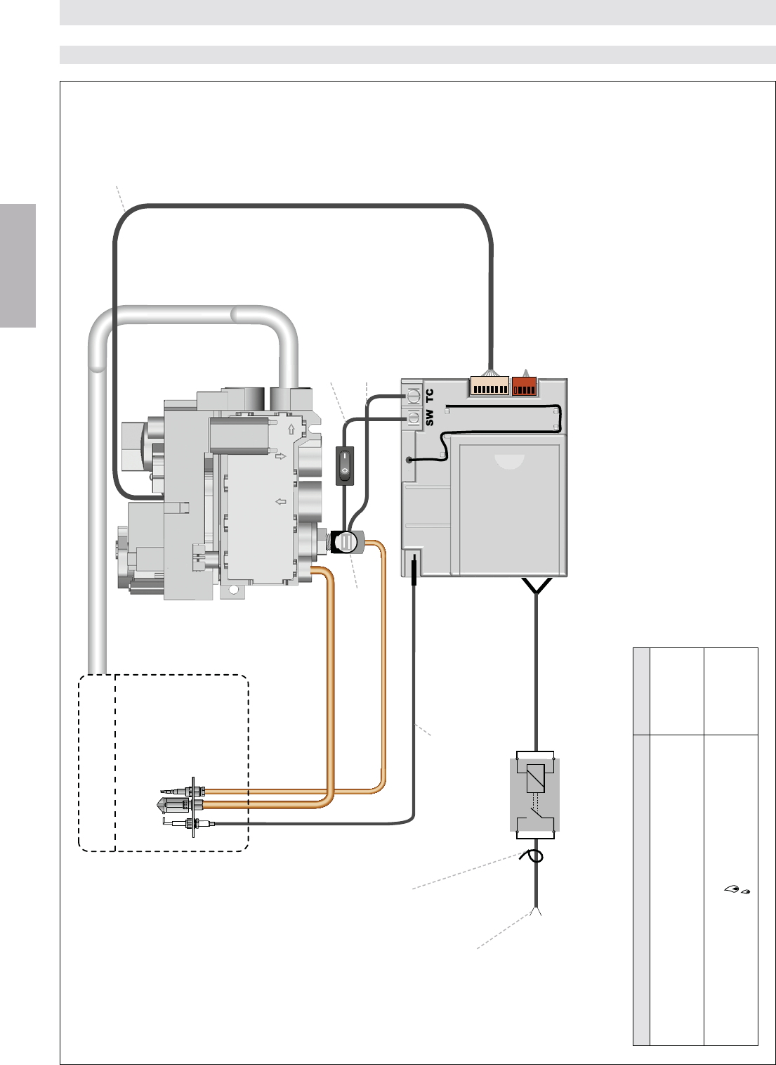
RELAY OPERATION (VOLT FREE CONTACT) (RF, IR)
Figure 14
Function Handset
G6R-H3(4)D15
G6R-H3(4)T16
G6R-H3(4)DV13
G6R-H3(4)TV14
!!!"
# $ $%!&'
# $ $$%!&
G6R-H3(4)D10
G6R-H3(4)T7
G6R-H3(4)DV11
G6R-H3(4)TV12
INSTALLATION INSTRUCTIONS FOR OEM USE ONLY
Pilot Burner
Receiver
G6R-R3(4)AU
Relay with Cable
G6R-CD (50 V/0,6 A)
G6R-CDB (240 V/5 A)
Ignition Cable
8 Wire Cable
Thermocurrent Cable SW
with ON/OFF Switch
Thermocurrent Cable TC
Interrupter Block
Depending on the handset version (see table) the auxiliary contact is switched
Auxiliary contact
to switch ON/OFF
an electrical load
For cable G6R-CDB
(to be mounted by installer)
GV60 Valve
Main Burner
13 / 84
© 2014 Mertik Maxitrol GmbH & Co. KG, All Rights Reserved.
ENGLISH
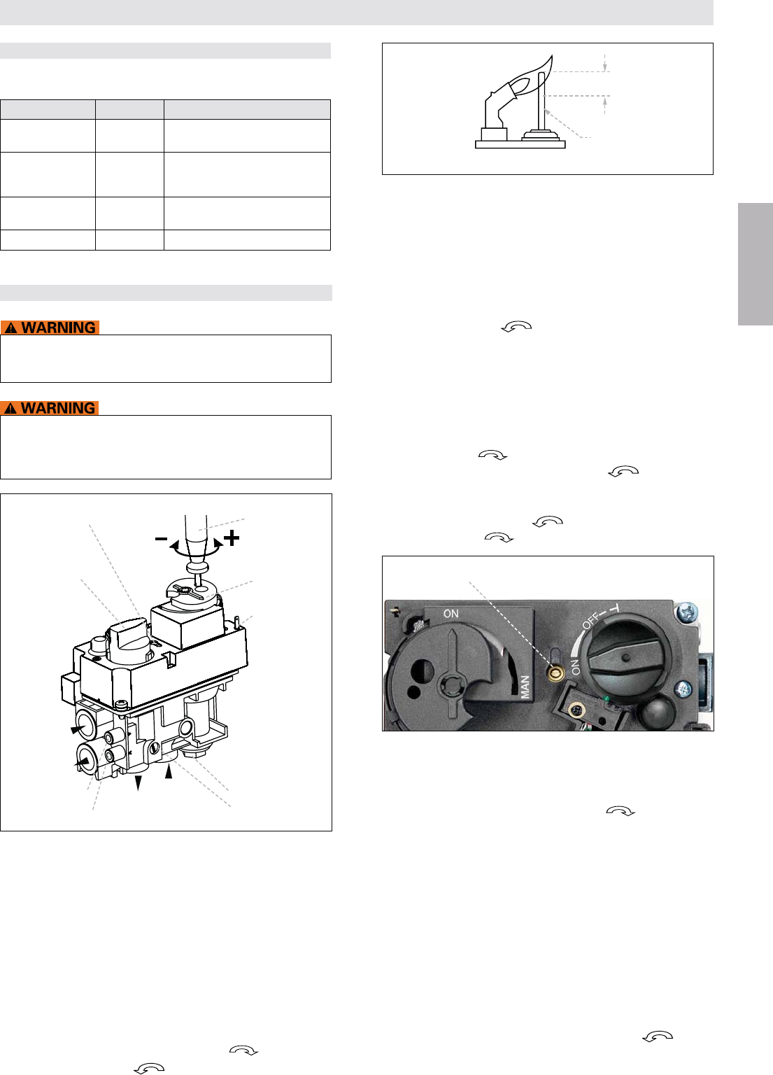
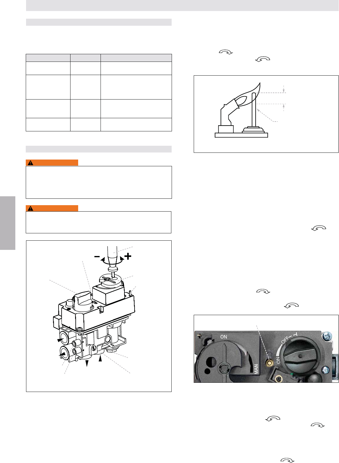
Pilot Flame Adjustment
(Vented Units Only)
-
-
1. The adjustment screw can be reached through a hole in
2. Turn the MANUAL knob to the ON position.
a screwdriver to reach the adjustment screw beneath.
4. Turn the adjustment screw clockwise to decrease
or counter-clockwise
Outlet Pressure Adjustment
(Vented Units Only)
STANDARD REGULATOR OR THROTTLE
(Throttle CE only)
1. Connect a pressure manometer to the valve outlet pres-
sure tap. Pressure tap is opened by turning the screw
counter-clockwise .
Pressure regulator or throttle are located under the cover
and 17).
2. Turn MANUAL knob and main valve knob to the ON posi-
tion.
-
ing clockwise (pressure regulator models), or de-
creased by turning counter-clockwise .
NOTE: Throttle model’s pressure is increased by turning
counter-clockwise ; or decreased by turning
clockwise .
Figure 17: Combination Control GV60, Cover
Pressure regulator or throttle
4. After adjustment, replace the plug.
by turning the screw(s) full clockwise .
Check all connections/pressure tap(s) for leaks.
by adjusting the gas valve, check the gas valve inlet pres-
sure using a manometer at the valve inlet pressure tap. If
the inlet pressure is in the normal range, replace the gas
valve; otherwise, take necessary steps to assure proper
gas pressure to the valve.
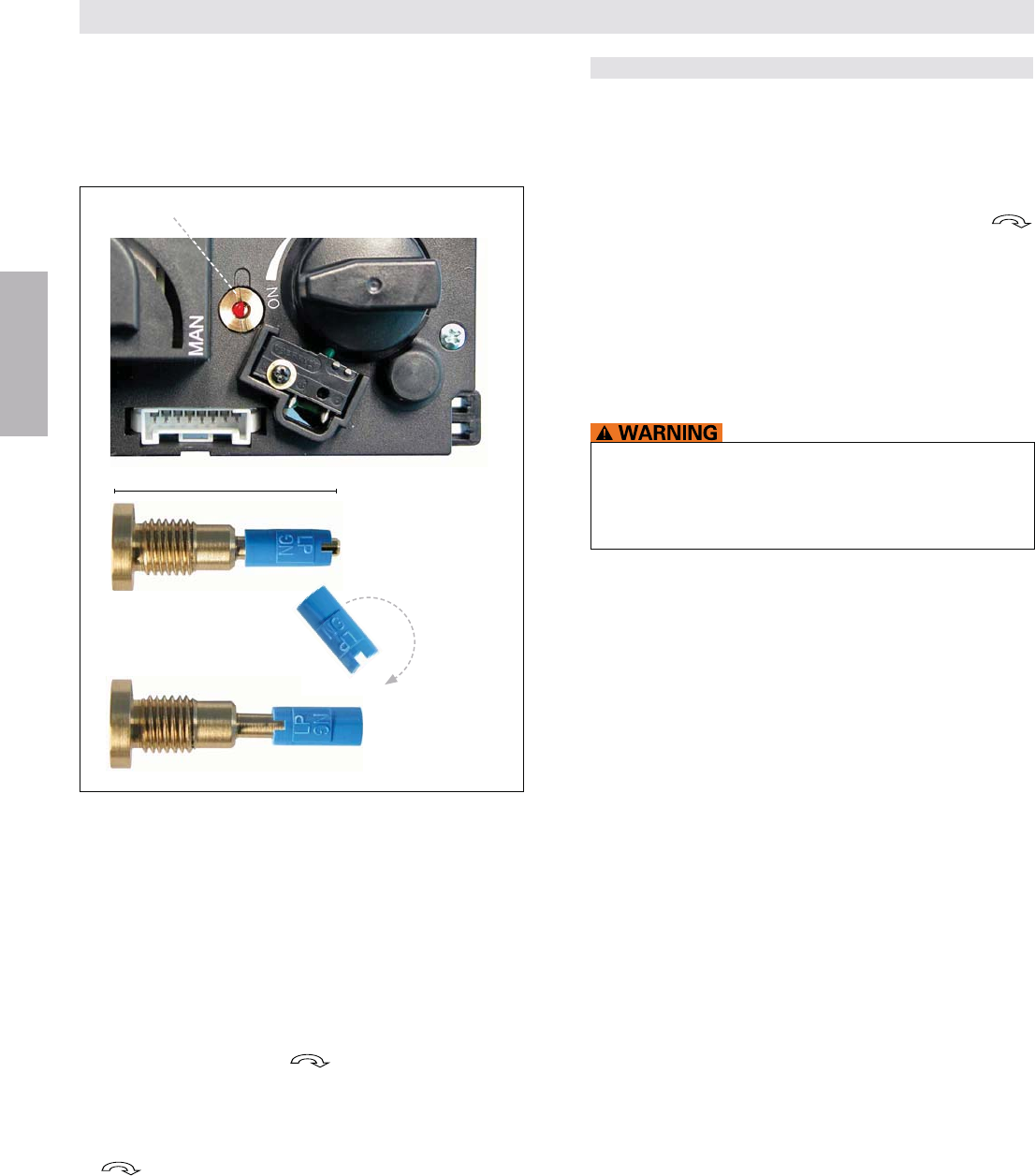
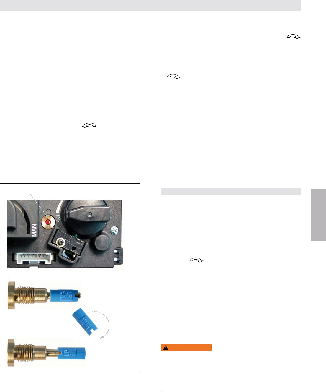
CONVERTIBLE PRESSURE REGULATOR
(optional)
Convertible regulators are designed to deliver either of two
change from one gas to the other, turn the conversion plug
to re-
move. Unsnap and remove the plastic part, rotate it 180°,
and then slide it back on the conversion plug until it snaps.
Vented gas appliances
Figure 16: Proper Flame Impingement on Thermocouple
Figure 15: GV60, Connections and Adjustment Options
Side Outlet
Side Inlet
Main Valve Knob MANUAL Knob
Bottom Outlet
Bottom Inlet
Pressure Regulator
or Throttle
$*+
Inlet Pressure Tap
Outlet Pressure Tap
Pilot Gas Adjust-
ment Screw (turn
with screwdriver)
Magnet Unit
;$$&+
Connection
Piezo Igniter
Tab 2.8 x 0.8 mm
KNOB POSITION FUNCTION
Main valve OFF <*$!!
valve.
Main valve ON
<$$!!**
if the pilot is lit and thermocouple is
+
MANUAL knob MAN Allows the pilot to be manually ignited
*$
MANUAL knob ON Allows for automatic ignition.
ADJUSTMENT
It is the appliance manufacturer’s responsibility to deter-
Do NOT attempt to remove screws from the top of gas
valve. Do NOT change any adjustments marked with
tamper indicating paint. Motor knob is not to be removed.
INSTALLATION INSTRUCTIONS FOR OEM USE ONLY
GAS CONTROL KNOB SETTINGS
>?
(10 to 13 mm)
Thermocouple
14 / 84
© 2014 Mertik Maxitrol GmbH & Co. KG, All Rights Reserved.
ENGLISH
FINAL CHECK
Observe several complete cycles to ensure proper opera-
tion. During these cycles the electronics will determine the
1. STOP! Read the safety information included before pro-
ceeding.
2. Turn main valve knob to the OFF, full clockwise
position.
O (OFF position).
gas is in the area around the appliance, including near the
If you detect gas STOP! Follow “WHAT TO DO IF
YOU SMELL GAS” in the safety information (page 3).
If no gas is present, proceed according to the Mertik Maxi-
trol Operating Instructions.
Minimum Gas Flow Adjustment
(Vented Units Only)
knob to OFF position and back until the valve opens.
2. The minimum rate can be set either by screwing in a cali-
minimum rate screw. Controls with adjustable screws
-
3. Turn the screw clockwise to decrease the minimum
stops.
5. Close pressure tap(s) by turning the screw(s) full clockwise
. Check all connections/pressure tap(s) for leaks.
Changing the Fuel Type
(Vented Units Only)
GV60 is suitable for all gas types and can be converted to
Adjustments of pressure regulator, minimum rate and pilot
gas are according to above-mentioned instructions. To con-
vert for LPG CE it is necessary to block the pressure regulator
by turning the regulator adjustment screw fully to the bottom
limit (or the throttle adjustment screw fully to the upper limit).
INSTALLATION INSTRUCTIONS FOR OEM USE ONLY
FIRE OR EXPLOSION HAZARD. Attempted disassembly
or repair can cause property damage, severe injury or
death. Do NOT disassemble the gas valve; it contains no
serviceable components.
Figure 18: Conversion from one gas to another
Conversion Plug
NG position
LP position
180°
Conversion Plug
Reinstate the conversion plug by screwing it clockwise until
it bottoms out.
NOTE: Do NOT adjust and/or alter any components marked
with tamper indicating paint.
15 / 84
© 2014 Mertik Maxitrol GmbH & Co. KG, All Rights Reserved.
ENGLISH
GENERAL NOTES
Radio Frequency Handset
433.92 MHz for Europe; 315 MHz for U.S. and for Canada.
This device complies with part 15 of the FCC Rules. Op-
eration is subject to the following two conditions: (1) This
device may not cause harmful interference, and (2) This
device must accept any interference received, including in-
terference that may cause undesired operation. Changes or
-
sible for compliance could void the user’s authority to oper-
NOTICE
Wiring of valve and receiver must be completed before start-
ing ignition. Failure to do so could damage the electronics.
Batteries – Handset
Batteries – Receiver
motor turns.
-
cludes mains power together with batteries in the receiver
for automatic backup in case of power outage.
-
ommended at the beginning of each heating season.
NOTICE
Only the Mertik Maxitrol AC Mains Adapter or one pre-
approved by Mertik Maxitrol can be used. Use of other
adaptors can render the system inoperable.
NOTICE
The handsets, receivers, wall switches, switch panels and
touchpads are not interchangeable with previous electron-
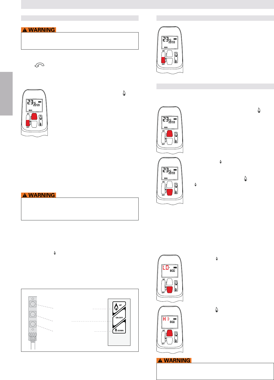
Figure 21: Receiver Reset Button
NOTICE
Replacement handsets for CSA models also must have
the same part number (see label).
SETTING THE ELECTRONICS CODE
(First time use only.)
Radio Frequency Handset
A code is selected automatically for all Mertik Maxitrol elec-
tronics from among 65,000 random codes available.The re-
ceiver has to learn the code of the handset:
second beep is long. After the second beep, release the
reset button.
(small
or the wiring is incorrect.
NOTE: -
ter changing the batteries of the handset or receiver.
OPERATING INSTRUCTIONS FOR OEM USE ONLY
Figure 20: Previous Handset
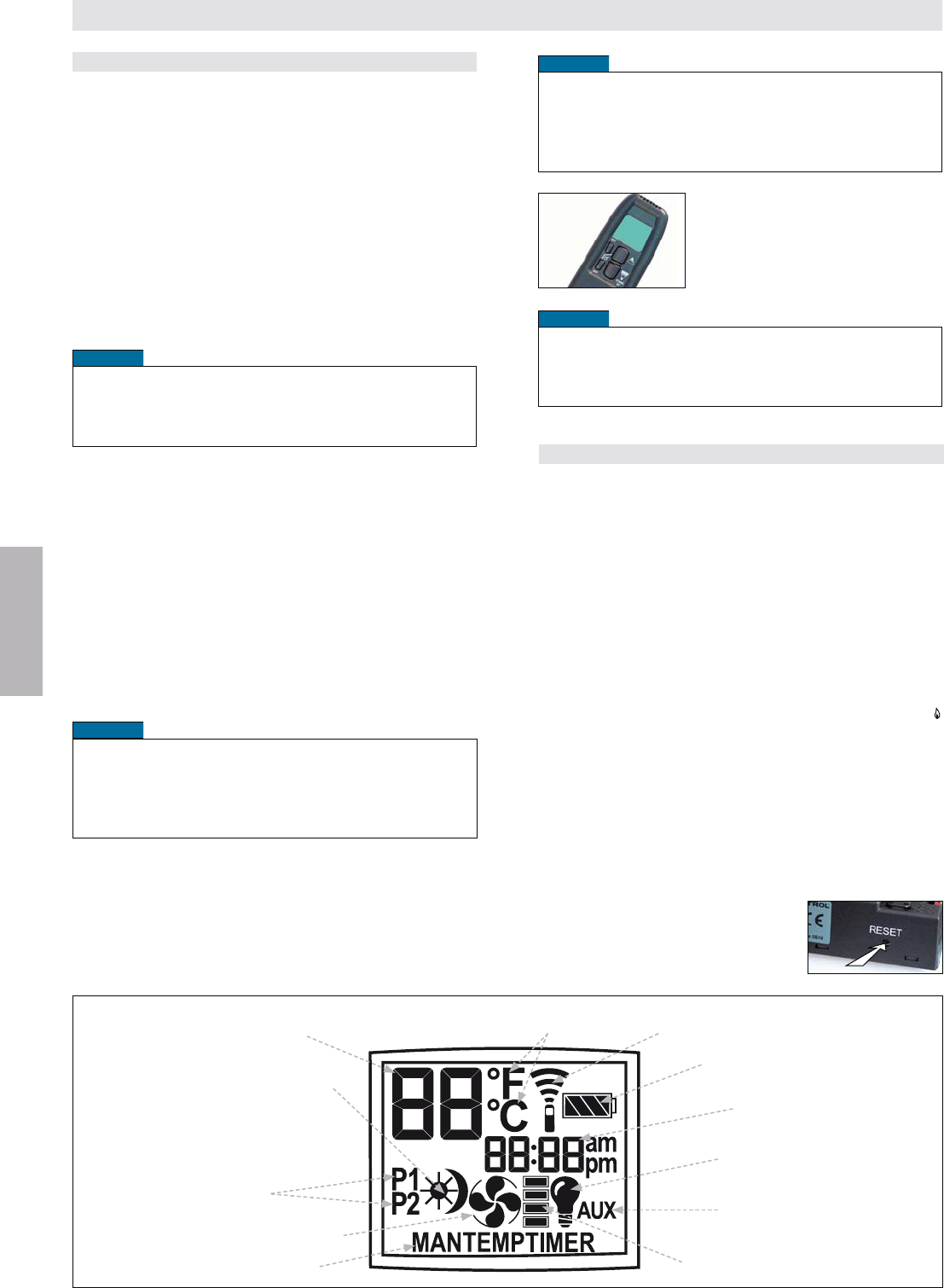
Light/Dimmer operation (page 17)
Fan operation (page 17)
Time setting (page 18)
Program timer setting (page 19)
Temperature
°C/24 hour or °F/12 hour Clock
setting (page 18)
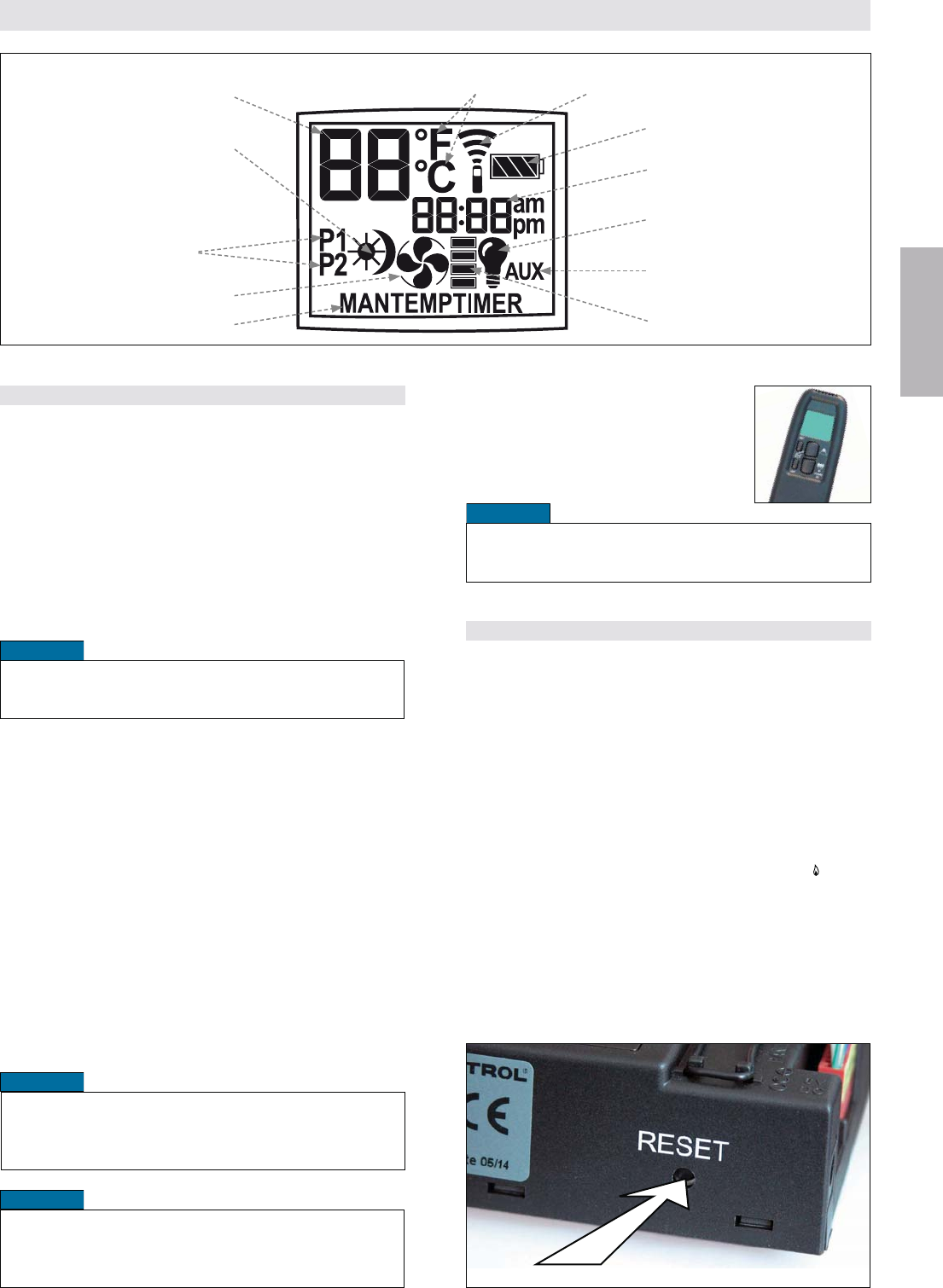
Fan level icon (page 17)
Solenoid Valve/Burner
OPEN and CLOSE (page 17)
ON/OFF Temperatures setting (page 18)
Battery status
Signal indicator
Modes of operation (page 17)
Figure 19
16 / 84
© 2014 Mertik Maxitrol GmbH & Co. KG, All Rights Reserved.
ENGLISH
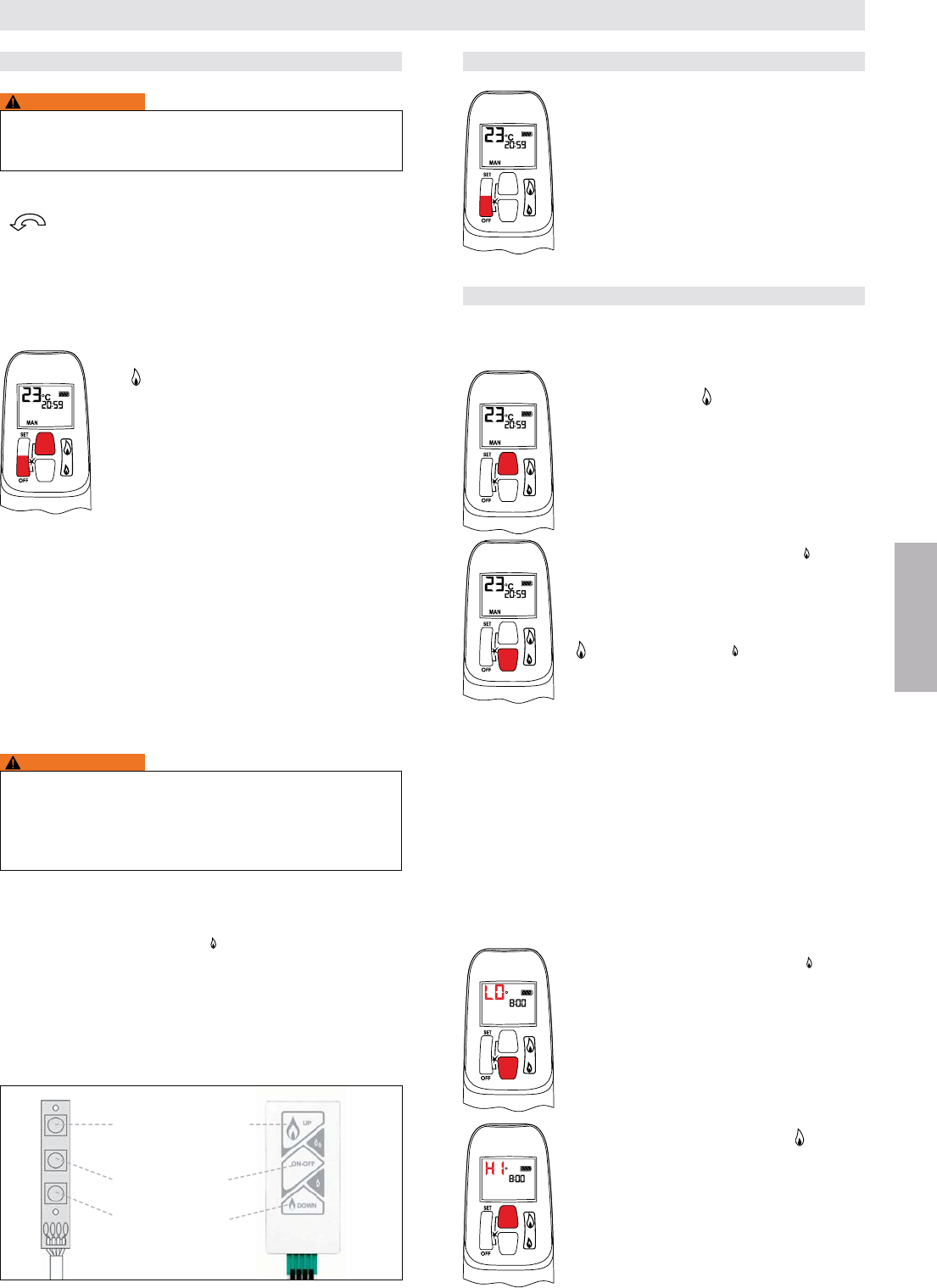
TO TURN OFF APPLIANCE
Handset
OFF button.
Wall Switch / Touchpad / Switch Panel
FLAME HEIGHT ADJUSTMENT
Handset
In standby mode: Press and hold (large
-
or
Wall Switch/Touchpad/Switch Panel
Designated Low Fire and High Fire
MAN
C
will be displayed.
NOTE:
MAN
C
displayed.
If the appliance will not operate, follow the instructions
“TURN OFF GAS TO APPLIANCE” (page 20).
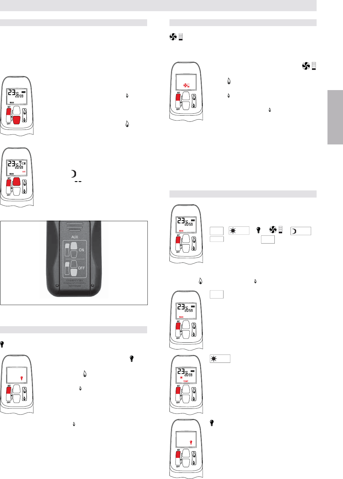
TO TURN ON APPLIANCE
on valve to the ON, full counter-clock-
wise position .
I (ON position).
Handset
(large
-
tons.
process.
automatically go into manual mode (CSA
version, CE version).
Wall Switch / Touchpad / Switch Panel
Press button “B”
If the pilot does not stay lit after several tries, turn the main
valve knob to OFF and follow the instructions “TURN OFF
GAS TO APPLIANCE” (page 20).
STANDBY MODE (Pilot Flame)
Handset
Press and hold
Wall Switch / Touchpad / Switch Panel
22) to set appliance
Figure 22: Switch Panel and Wall Switch/Touchpad
B) ON/OFF
OPERATING INSTRUCTIONS FOR OEM USE ONLY
17 / 84
© 2014 Mertik Maxitrol GmbH & Co. KG, All Rights Reserved.
ENGLISH
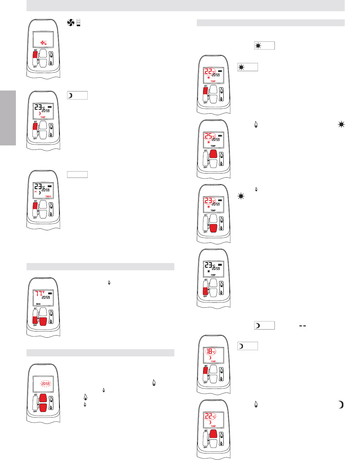
TO OPEN AND CLOSE SOLENOID VALVE/BURNER
NOTE: The latching solenoid valve cannot operate manu-
ally. If the battery runs down it will remain in the last
operating position. During normal operation the sole-
noid valve will be reset to the ON position when the
GV60 is switched OFF remotely.
Burner are ON.
SET and (small
Printed instructions are on the battery cover
SET and (large
AUX symbol on the display indicates the so-
lenoid valve is OPEN.)
NOTE: The operation of the AUX is blocked
in timer OFF mode, when the setting
of the Nighttime Setback Tempera-
ture is “ ”.
Figure 23: Instructions for Latching Solenoid Valve (on battery cover)
Burner OFF
Burner ON
LIGHT/DIMMER OPERATION
Light/Dimmer
(light
turn ON the light or increase brightness.
-
crease brightness.
shuts OFF the light.
and hold the
NOTE: The light bulb icon is displayed during light/dim-
mer setting only. 8 seconds after the light/dimmer
has been set, the handset will automatically go into
temperature control mode (CSA version) or manual
mode (CE version).
OPERATING INSTRUCTIONS FOR OEM USE ONLY
CIRCULATING FAN OPERATION
Circulating Fan
The circulating fan has 4 speed levels from low (1 bar) to
high (4 bars).
and increase fan speed.
fan speed.
-
ton until all 4 speed level bars disappear.
NOTE: 8 seconds after the fan has been set, the handset
will automatically go into temperature control mode
(CSA version) or manual mode (CE version). The
fan starts 4 minutes after the gas opens (from OFF
or from pilot) at maximum speed and goes to the
displayed level after 10 seconds. The fan stops 10
minutes after the gas is OFF or at pilot.
MODES OF OPERATION
mode of operation in the following order:
MAN
TEMP
TEMP
TIMER
MAN
.
NOTE: Manual mode can also be reached by pressing either
the
MAN
Manual Mode
TEMP
Daytime Temperature Mode
(Appliance must be in standby mode; pilot
ignited)
The room temperature is measured and
compared to the set temperature. The
to achieve the Daytime Set Temperature.
Light/Dimmer Setting Mode
Turns light/dimmer ON and OFF and ad-
justs brightness.
18 / 84
© 2014 Mertik Maxitrol GmbH & Co. KG, All Rights Reserved.
ENGLISH
OPERATING INSTRUCTIONS FOR OEM USE ONLY
Circulating Fan Setting Mode
Turns circulating fan ON and OFF and ad-
justs fan speed.
TEMP
Nighttime Setback Temperature
Mode
(Appliance must be in standby mode; pilot
ignited)
The room temperature is measured and
compared to the Nighttime Setback Tem-
-
matically adjusted to achieve the Nighttime
Setback Temperature.
TIMER
Timer Mode
(Appliance must be in standby mode; pilot
ignited)
The Timers P1 and P2 (Program 1, Pro-
gram 2) each can be programmed to go ON
see Timer Programming Mode.
NOTE: The display shows the set tempera-
ture every 30 seconds.
SETTING °C/24 HOUR OR °F/12 HOUR CLOCK
OFF and
display changes from Fahrenheit/12 hour
clock to Celsius/24 hour clock and vice ver-
sa.
SETTING THE TIME
a) Installing the battery or
b) Simultaneously pressing the (large
-
ute.
-
ual mode.
SETTING THE ON/OFF TEMPERATURES
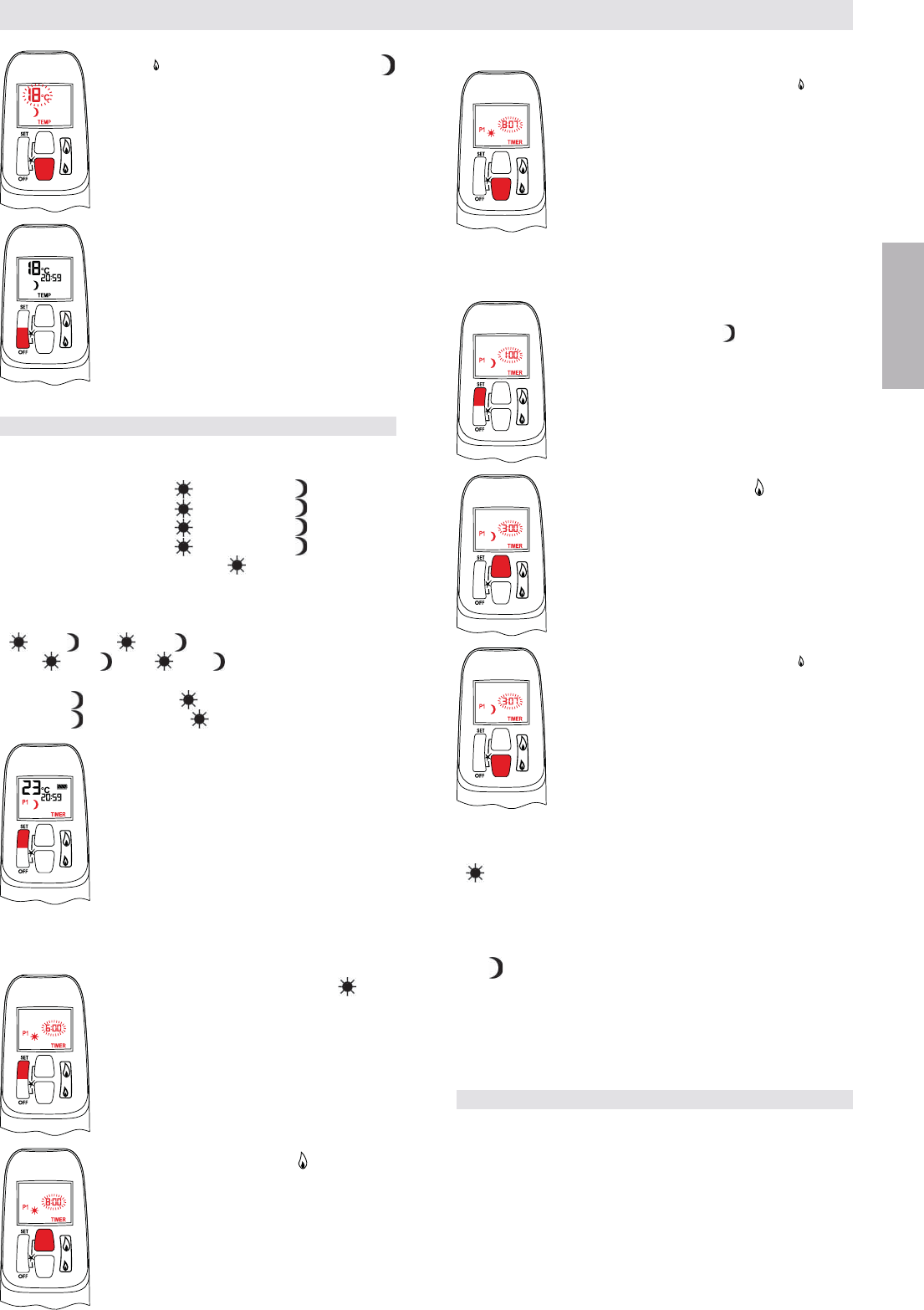
Setting the “DAYTIME” Temperature
DEFAULT SETTINGS:
TEMP
(sun), 23 °C/74 °F
SET button to scroll to TEMP
TEMP
(sun) mode. Hold the SET button
until the TEMP
Daytime Set Temperature.
Daytime Set Temperature.
OFF or simply wait to complete pro-
gramming.
Setting the “NIGHTTIME SETBACK” Temperature
DEFAULT SETTINGS:
TEMP
(moon), “ ” (OFF)
SET button to scroll to TEMP
TEMP
(moon) mode. Hold the SET button
Nighttime Setback Temperature.
19 / 84
© 2014 Mertik Maxitrol GmbH & Co. KG, All Rights Reserved.
ENGLISH
Nighttime Setback Temperature.
-
gramming.
SETTING PROGRAM TIMERS
Default Settings
CE: Program 1: P1 : 6:00 P1 : 8:00
Program 2: P2 : 23:50 P2 : 23:50
CSA: Program 1: P1 : 6:00am P1 : 8:00am
Program 2: P2 : 11:50pm P2 : 11:50pm
per day.
am, ends at 11:50pm.
< P2 .
= P1 or P2 = P2 the timer is deactivated.
CE: P2 23:50 and P1 0:00
CSA: P2 11:50am and P1 12:00am
SET button.
Setting P1 ON Time
SET button until P1 and (sun)
button.
OPERATING INSTRUCTIONS FOR OEM USE ONLY
(small
Setting P1 OFF Time
SET button to scroll to setting
P1 OFF time. P1 and (moon) are dis-
button.
(small
Setting P2 ON Time
SET button to scroll to setting P2 ON time. P2
Setting P2 OFF Time
SET button to scroll to setting P2 OFF time.
P2
OFF or wait. The handset will automatically save your
changes.
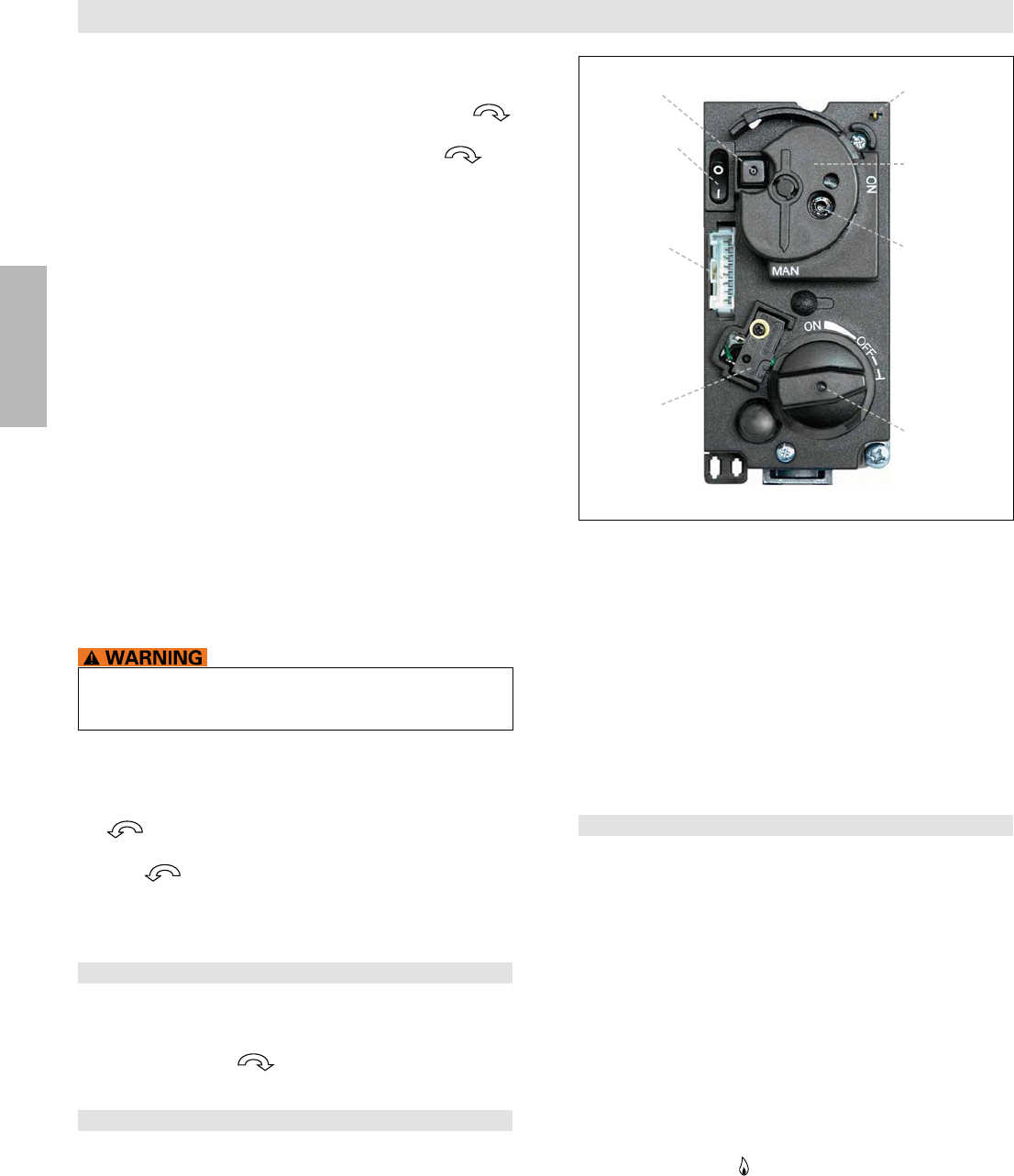
MANUAL OPERATION
(Only possible, when MANUAL knob is used)
match.
When turning main valve knob, do NOT force. Knob has a
slip clutch that clicks until the end stops are reached. This
-
ment to pilot standby position.
20 / 84
© 2014 Mertik Maxitrol GmbH & Co. KG, All Rights Reserved.
ENGLISH
OPERATING INSTRUCTIONS FOR OEM USE ONLY
1. STOP! Read the safety information included before pro-
ceeding.
2. Turn main valve knob to the OFF, full clockwise
position.
3. Turn MANUAL knob to the MAN, full clockwise po-
sition.
4. Place ON/OFFO (OFF position).
gas is in the area around the appliance, including near
If you detect gas STOP! Follow “WHAT TO
DO IF YOU SMELL GAS” in the safety information on
page 2. If no gas is present, proceed to step 6.
6. Place ON/OFFI (ON position).
7. With the MANUAL knob in MAN position a manual pilot
valve operator and piezo ignitor (optional) are accessible.
8. Fully push down manual pilot valve operator and hold in,
IGNITION WITH MATCH:
Immediately light the pilot with a match, while continuing
to hold in the manual pilot valve operator for about one
(1) minute after the pilot is lit. Release manual pilot valve
repeat.
IGNITION WITH PIEZO IGNITOR:
Change the ignition cable from the receiver to the valve
If the pilot does not stay lit after several tries, turn the main
valve knob to OFF and proceed to step 12.
9. If applicable, replace pilot access panel before proceed-
ing.
10. Turn MANUAL knob to the ON, full counter-clockwise
position.
11. Turn main valve knob to the full ON, full counter-clock-
wise position.
12. If the appliance will not operate, follow the instructions
“TURN OFF GAS TO APPLIANCE”.
TO TURN OFF GAS TO APPLIANCE
O (OFF position).
2. If gas control is accessible turn main valve knob to the
OFF full clockwise position.
AUTOMATIC TURN DOWN
6 Hour no Motor Movement
(CSA version)
a 6 hour period. In Temperature/Timer Mode if the ambi-
continue to function normally. The valve will turn to pilot
-
perature remain the same over a 6 hour period.
Figure 24: Combination control, cover
8 Wire
Receiver jack
Micro switch
MANUAL knob
in MAN position
Main valve knob
in OFF position
Manual pilot
valve operator
Piezo ignitor
(optional)
ON/OFF switch
(optional) in
ON Position
Connection
piezo ignitor
tab 2.8 x 0.8 mm
Receiver Overheating
(only if module is connected)
is higher than 140 °F (60 °C). The main burner comes back
on only when the temperature is below 140 °F (60 °C).
1 Hour Turn Down for Special Receiver
AUTOMATIC SHUT OFF
Low Battery Receiver
is interrupted.
Five Day Shut Off
(CSA version)
Second Thermocouple Shut Off
(optional)
completely ignite approximately 20 seconds after ignition
or after pushing the
NOTE: Before the next ignition there is a 2 minute waiting
period. If the thermocouple is still too hot, then you
will hear a long beep.

42 / 84
© 2014 Mertik Maxitrol GmbH & Co. KG, tous droits réservés.
FRANCAIS
SOMMAIRE
IMPORTANT INSTRUCTIONS DE SÉCURITÉ ............................. 43
NOUVELLE CONCEPTION DE
LA TÉLÉCOMMANDE INFORMATIONS ........................................43
INSTRUCTIONS D’INSTALLATION
Application ............................................................................... 43
Composants ............................................................................ 43
........................................................ 45
Branchements du gaz ............................................................. 46
Effecteur un test de fuite de gaz .............................................. 47
Connexions des fils ................................................................. 47
Paramètres du bouton de commande du gaz ......................... 54
Ajustage .................................................................................. 54
Contrôle final ........................................................................... 55
INSTRUCTIONS DE SERVICE
Notes Générales ..................................................................... 56
........................................... 56
Allumer l’appareil ..................................................................... 57
Arrêter l’appareil ...................................................................... 57
Ajustage de la hauteur de flamme .......................................... 57
Pour ouvrir et fermer l’électrovanne/le brûleur ........................ 58
Fonctionnement éclairage/variateur ........................................ 58
Fonctionnement du ventilateur circulant ................................. 58
Modes de fonctionnement ....................................................... 58
Paramètre horloge °C/24 heures ou °F/12 heures .................. 59
Réglage de l’heure .................................................................. 59
Configuration des températures ON/OFF ............................... 59
Réglage du programme des horloges ..................................... 60
Fonctionnement Manuel .......................................................... 61
Arrêter l’alimentation en gaz vers l’appareil ............................ 61
..................................................... 62
.................................................................... 62
43 / 84
© 2014 Mertik Maxitrol GmbH & Co. KG, tous droits réservés.
FRANCAIS
AVERTISSEMENT
AVERTISSEMENT
IMPORTANT INSTRUCTIONS DE SÉCURITÉ
selon toutes les normes et réglements locaux.
QUE FAIRE EN CAS D’ODEUR DE GAZ
-
tenance, ou par le fournisseur de gaz.
L’installation doit être conforme aux législations locales, ou en l’absence de législation locale, au Code national du gaz com-
tuyauteries et conduites doivent être conformes aux législations et ordonnances locales.
RISQUE D’ÉLECTROCUTION
ou la mort.
-
tations locales. La maintenance et l’installation doivent être effectuées par un technicien formé et expérimenté.
NOUVELLE CONCEPTION DE LA TÉLÉCOMMANDE
La nouvelle version de la télécommande GV60 (G6R-H...FB, G6R-H... FW) fonctionne exac-
tement comme la version précedente (G6R-H...). Seuls les symboles sur les touches ont été
changées (voir le tableau «Attributions de touches» pour la correspondance des symboles).
INDICATION ATTRIBUTIONS DES TOUCHES
G6R-H...FB(W) G6R-H...
=
=
=
=
=
44 / 84
© 2014 Mertik Maxitrol GmbH & Co. KG, tous droits réservés.
FRANCAIS
INSTRUCTIONS D’INSTALLATION UNIQUEMENT POUR UTILISATION SELON
LES DIRECTIVES DU FABRICANT
Figure 7: Infrarouges (IR)
Câble avec relais
G6R-CL... (en option)
Télécommande à infrarouge
G6R-HIO...
(FB(W))
Capteur d’infrarouges
G6R-IRC
Récepteur
G6R-RIAE
Figure 4: Fonction supplémentaire RF: VENTILATEUR – éclairage/variateur – électroaimant de verrouillage
Électrovanne
(avec câble)
GV-S60
Câble récepteur-module V
G6R-CBV...
Module V
G6R-BU..., G6R-BE...
Récepteur
G6R-R3(4)AU...
Figure 6: RF 2e Thermocouple OptionFigure 5: Adaptateur principal
G60-ZMA3
avec branchements pour
Europe, Royaume-Uni et
États-Unis
Récepteur
G6R-R3(4)AUT Câble de 2e thermocouple
G60-ZCTC...
Figure 2: Exploitation
Panneau de commande
avec câble G6R-SPN-... Commutateur
mural américain
G6R-ZWSN..-...
Commutateur mural
européen G6R-ZWSE-... Pavé de touches
G6R-TPN-...
Commutateur mural/pavé de
touches à câble G6R-CWSN-...
Figure 3: RF de base
Câble d’allumage
G60-ZKIS...
@J%QY+
récepteur-GV G6R-C...
Bloc interrupteur
G60-ZUS... Câble thermoélectrique pour
interrupteur-récepteur TC
G60-ZKIRSS/...
Bloc gaz
GV60
Câble thermoélectrique interrupteur-récepteur SW …
sans bouton ON/OFF
G60-ZKIRSWS/...
ou
avec bouton ON/OFF
G60-ZSKSS/..., G60-ZSKLS/...,
Câble avec relais
G6R-CD..., G6R-CDB (en option)
K
IS.
..
Caisson de batteries
G60-ZB90/...
Récepteur standard
G6R-R3(4)AM...
Récepteur universel
G6R-R3(4)AU...
ou
2e thermocouple G60-ZPT…
Câble de mise
à la terre
G60-ZCGTC/…
d
e mise
r
e
C
GTC
/…
APPLICATION
gaz dotés de veilleuses et de systèmes ODS.
COMPOSANTS
Figure 1: Télécommande, chacun sur le côté droit est la nouvelle version
Télécommande à fréquence radioélectrique
standard
G6R-H3S...(FB(W))
G6R-H4S...(FB(W))
Télécommande à fréquence radioélectrique
Q+!
G6R-H3D... (FB(W))
G6R-H4D... (FB(W))
Télécommande à fréquence radio électrique
pour minuterie/thermostat
G6R-H3T...(FB(W))
G6R-H4T...(FB(W))
tr
iqu
e
r
iqu
ctr
iqu
e
G
e
ctr
iqu
e
e
ct
45 / 84
© 2014 Mertik Maxitrol GmbH & Co. KG, tous droits réservés.
FRANCAIS
INSTRUCTIONS D’INSTALLATION
SPÉCIFICATIONS TECHNIQUES
Récepteur RF sans piles: 176 °F (80 °C)
Récepteur RF avec piles: 131 °F (55 °C)
Récepteur infrarouge avec/sans piles: 131 °F (55 °C)
Télécommande: 140 °F (60 °C)
Commutateur mural/pavé de touches: 176 °F (80 °C)
Panneau de commande: 221 °F (105 °C)
Module: 176 °F (80 °C)
Capteur d’infrarouges: 176 °F (80 °C)
CE: 433,92 MHz pour l’Europe
CSA: 315 MHz pour les Etats-Unis et pour le Canada.
Le présent appareil est conforme aux CNR d'Industrie
Canada applicables aux appareils radio exempts de
licence. L'exploitation est autorisée aux deux condi-
tions suivantes: (1) l'appareil ne doit pas produire
de brouillage, et (2) l'utilisateur de l'appareil doit
si le brouillage est susceptible d'en compromettre le
fonctionnement.
1 x 9 V, nouvelle conception 2012: 3 x 1,5V „AAA“
INDICATION
Seul l’adaptateur secteur Mertik Maxitrol ou un model
approuvé par Mertik Maxitrol peuvent être utilisés. L’uti-
lisation d’autres adaptateurs peut empêcher le fonction-
nement du système.
MODULE V
CE: Entrée: 230 VCA/50 Hz; 210 VA
Sortie: 230 VCA/50 Hz; 100 VA
Fusible intégré: 2,5 A
CSA: Entrée: 115 VCA/60 Hz; 210 VA
Sortie: 115 VCA/60 Hz; 100 VA
Fusible intégré: 2,5 A
Commande de combinaison du gaz selon les autorisa-
COMBUSTIBLES
EN 437 1, 2 et 3.
LP-air.
HOMOLOGATIONS
2009/142/EG et EN
298-2003, DIN EN 126
CSA: ANSI Z21.78/CSA 6.20 pour les Etats-Unis & le
Canada
Télécommande: Fiche explicative GADAC B12
CE: 2,5
m³/h
d’air
BTU/h
CE: Classe C selon EN 88
BTU/h
mbar)
mbar)
POSITION DE MONTAGE
commande du gaz.
CE: 50 mbar (20” W.C.)
CSA: ½ psi (34,5 mbar)
RACCORDEMENT PRINCIPAL AU GAZ
extérieur de 12
mm, 10
mm, 8
mm, 6
mm.
mm, 10
mm, 8
mm, 6
mm.
Flanc ou fond
ET À LA SORTIE
CE: 35 Nm
CSA: 280 pouces par livre
RACCORDEMENT DE GAZ SUR LA VEILLEUSE
CE: M10x1 pour les conduites 4 mm ou 6 mm
THERMOCOUPLE/BOC INTERRUPTEUR
11/32-32 UNS, M10x1, M9x1, M8x1
INDICATION
Les télécommandes, récepteurs, les commutateurs muraux,
les panneaux de commandes et les pavés de touche ne
précédents.
UNIQUEMENT POUR UTILISATION SELON
LES DIRECTIVES DU FABRICANT
16
46 / 84
© 2014 Mertik Maxitrol GmbH & Co. KG, tous droits réservés.
FRANCAIS
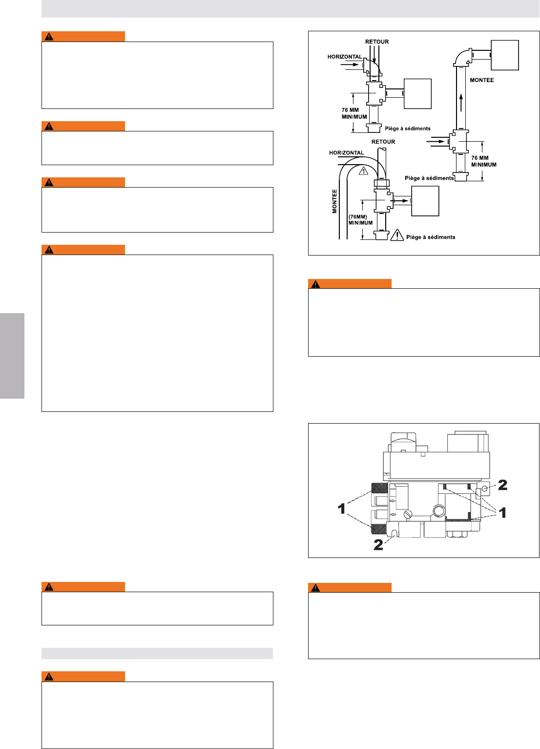
Figure 8: Piège à sédiments (si nécessaire)
ALIMENTATION
GAZ
ALIMENTATION
GAZ
ALIMENTATION
GAZ
BLOC GAZ
BLOC GAZ
BLOC GAZ
AVERTISSEMENT
Utiliser des conduites neuves et correctement alésées
soient carrées, ébavurées et propres. Tous les raccords
de tuyauterie doivent être droits et non tordus.
-
Figure 9: 1 = Zones de serrage, 2 = Points de montage
AVERTISSEMENT
Ne pas serrer excessivement les branchements. Un
serrage excessif peut endommager le corps du bloc
(voir «COUPLE DE ROTATION MAXI ADMISSIBLE À
», page 45).
Raccordement principal au gaz
(branchements des tuyauteries)
®/PTFE.
3. Faire glisser l’écrou et la virole et insérer la conduite
AVERTISSEMENT
Veuillez lire soigneusement les présentes instructions. Tout
Le produit doit être installé et exploité selon tous les codes
et réglements locaux.
AVERTISSEMENT
AVERTISSEMENT
manipulation; le bouton du moteur ne doit pas être démonté.
AVERTISSEMENT
1. Arrêter l’alimentation en gaz au robinet de service de
l’appareil avant de démarrer l’installation et effectuer un
test de fuite de gaz une fois l’installation terminée.
d’alimentation en gaz pour éviter toute contamination du
3. Enclencher ou ouvrir les boutons de commande du gaz
n’est pas possible d’enclencher ni d’ouvrir un bouton
incendie ou une explosion.
Emplacement
graisse ou une chaleur excessive.
Pour assurer un fonctionnement correct, veuillez respecter
les consignes suivantes:
toute inondation ou exposition aux éclaboussures d’eau.
AVERTISSEMENT
l’utilisation en intérieur.
BRANCHEMENTS DU GAZ
AVERTISSEMENT
Risques d’incendie ou d’explosion. Peut entraîner des
dommages matériels, des blessures graves ou la mort.
Ne pas raccorder la conduite sur le branchement du robinet
INSTRUCTIONS D’INSTALLATION UNIQUEMENT POUR UTILISATION SELON
LES DIRECTIVES DU FABRICANT
47 / 84
© 2014 Mertik Maxitrol GmbH & Co. KG, tous droits réservés.
FRANCAIS
Raccordement principal au gaz
(branchements des conduites)
®/PTFE.
s’il est inséré trop profondément.
Raccordement de gaz sur la veilleuse
(branchements des tuyauteries)
1. Ne pas utiliser de combinaison de joints pour tuyauterie ni
®/PTFE.
3. Insérer la tuyauterie de la veilleuse dans la sortie de celle-ci
encore ¾ de tour pour obtenir un joint étanche au gaz.
5. Brancher l’autre extrémité de la conduite au brûleur de la
veilleuse.
AVERTISSEMENT
Le bloc gaz doit être débranché du système de conduites
d’alimentation en gaz pendant tout contrôle de pression
½ psi (3,5 kPa CSA; 50 mbar CE). Un excès de pression
un dysfonctionnement.
EFFECTUER UN TEST DE FUITE DE GAZ
-
diatement après l’installation du bloc gaz et l’ouverture
du gaz. Effectuer cette action avant d’essayer d’exploiter
test anti-fuite autorisée sur les branchements des conduites
3. Si aucune fuite n’est détectée, allumer le brûleur principal.
solution de test anti-fuite autorisée sur tous les branche-
ments des conduites et tuyauteries (adaptateurs inclus) et
sur l’entrée et la sortie du bloc gaz. La présence de bulles
5. Si une fuite est détectée, resserrer les branchements des
RAN-
CHEMENT DU GAZ» (page 46).
AVERTISSEMENT
Il ne doit se produire absolument aucune fuite, sinon il y a
jamais utiliser si une fuite est détectée.
INSTRUCTIONS D’INSTALLATION UNIQUEMENT POUR UTILISATION SELON
LES DIRECTIVES DU FABRICANT
CONNEXIONS DES FILS
INDICATION
de démarrer l’allumage. Tout non-respect peut endomma-
approprié.
Empêcher la pénétration de particules externes au-dessous
le plus facilement accessible pour l’utilisateur.
Circuit de thermocouple
La résistance totale du circuit de thermocouple doit être
réduire pour assurer un fonctionnement correct.
INDICATION
L’utilisation du bloc interrupteur Mertik Maxitrol est recom-
mandée. Conserver le branchement du bloc interrupteur
serré de la conduite de thermocouple pendant l’installation
tomber en panne.
Installer le bloc interrupteur en le serrant ¼ de tour de plus
laiton du bloc interrupteur.
-
serrage manuel (2…3 Nm).
Câble d’allumage
INDICATION
contact avec des objets ou des bords tranchants.
étincelles.
Récepteur
INDICATION
Pour garder le récepteur exempt de poussières, de crasse
et d’humidité, ne pas retirer le récepteur du sac en plas-
1. Insérer les piles ou brancher l’adaptateur principal de CA.
Le module de ventilateur circulant/variateur d’éclairage
comprend un adaptateur principal.

48 / 84
© 2014 Mertik Maxitrol GmbH & Co. KG, tous droits réservés.
FRANCAIS
L’adaptateur principal permet d’utiliser les piles pour la
réserve (RF seulement).
-
tion ON.
3. Le récepteur doit apprendre le code de la télécommande:
-
-
tialisation. Dans les 20 secondes suivantes, appuyer sur le
bouton
est réglé.
NOTE:
cas de remplacement des piles dans la télécom-
mande ou le récepteur.
-
ser l’antenne et la déplacer dans une
ci-dessous).
métal environnant peut réduire considérablement la récep-
également la réception.
INDICATION
L’antenne ne doit pas se croiser ni entrer en contact avec
pas fonctionner.
Versions IR
Placer l’aiguille infrarouge dans une position convenable. La
transmission du signal infrarouge nécessite une ligne de vue.
AVERTISSEMENT
RISQUE D’ÉLECTROCUTION:
-
riels, corporels, ou la mort.
réglementations locales. La maintenance et l’installation
doivent être effectuées par un technicien de service formé
et expérimenté.
présente un dommage.
Module V
page 50
2
50).
Commencer par brancher l’éclairage et le ventilateur, puis
INSTRUCTIONS D’INSTALLATION UNIQUEMENT POUR UTILISATION SELON
LES DIRECTIVES DU FABRICANT
49 / 84
© 2014 Mertik Maxitrol GmbH & Co. KG, tous droits réservés.
FRANCAIS
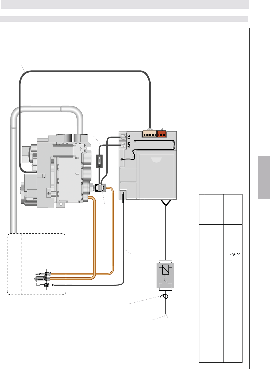
ON-OFF
UP
DOWN
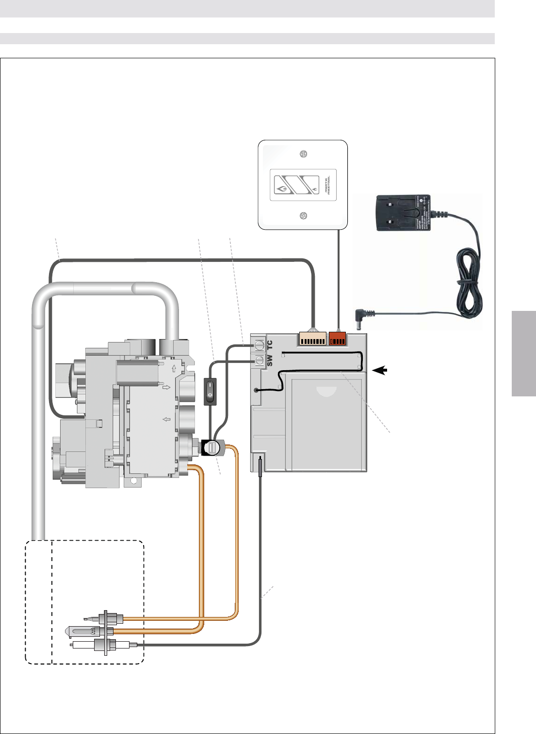
Figure 10
BASE (RF)
Brûleur principal
Bloc gaz GV60
Commutateur
mural
(en option)
Récepteur
G6R-R3(4)AM...
ou
G6R-R3(4)AU...
Câble thermoélectrique SW
avec bouton ON/OFF
Câble thermoélectrique TC
Bloc interrupteur
Bouton RESET Adaptateur principal
(en option)
Câble d’allumage
INSTRUCTIONS D’INSTALLATION UNIQUEMENT POUR UTILISATION SELON
LES DIRECTIVES DU FABRICANT
Brûleur pilote
Antenne
50 / 84
© 2014 Mertik Maxitrol GmbH & Co. KG, tous droits réservés.
FRANCAIS
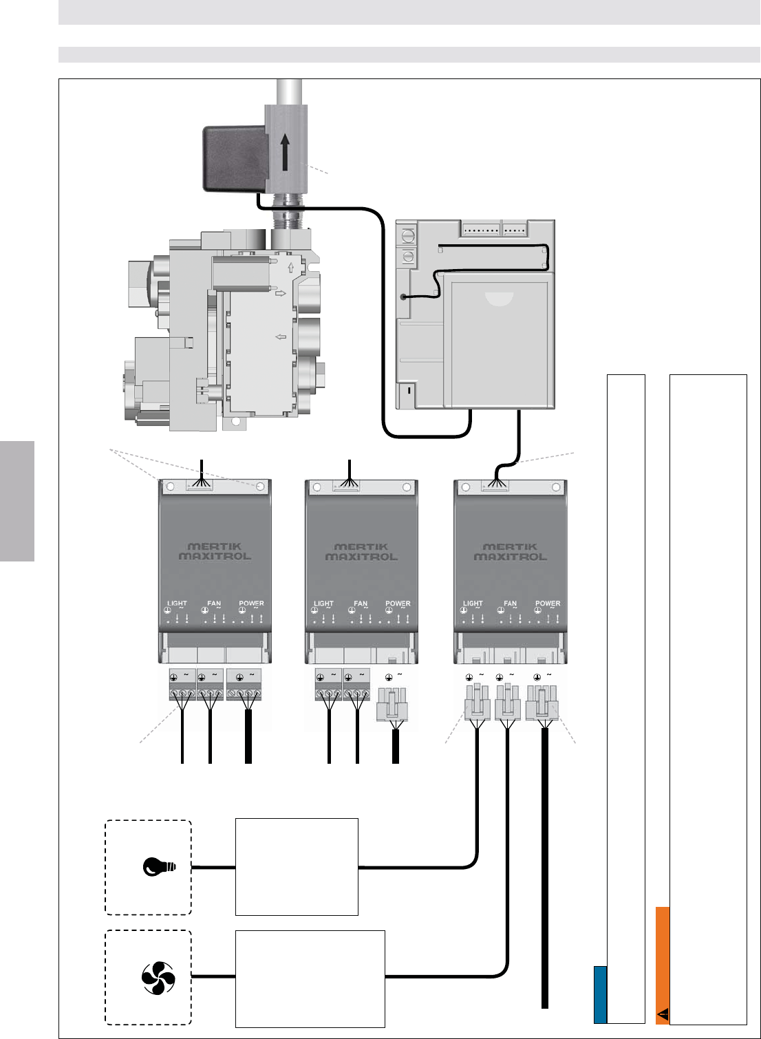
12
12 12 12
12 12
12 12 12
12 12 12
12 1212
12 12 12
Figure 11
Récepteur
G6R-R3(4)AU...
Câble V pour récepteur de module
Électrovanne
L'électrovanne
-
guration éteint le
brûleur secondaire
en laissant le
brûleur première
allumé. Consulter
Mertik Maxitrol pour
-
rations.
G6R-BU(E)AV2
G6R-BU(E)SV2
G6R-BU(E)MV2
Molex 39-01-4031
Molex 39-01-4041
FONCTION SUPPLEMENTAIRE: VENTILATEUR – ECLAIRAGE/VARIATEUR – ÉLECTROVANNE (RF)
AWG maxi: 12/2,5 mm2
AVERTISSEMENT
RISQUE D’ÉLECTROCUTION
locales. La maintenance et l’installation doivent être effectuées par un technicien de service formé et expérimenté.
Pas pour une
diode électrolumi-
nescente (LED)
et pas pour une
-
mie d’énergie
INSTRUCTIONS D’INSTALLATION UNIQUEMENT POUR UTILISATION SELON
LES DIRECTIVES DU FABRICANT
4 niveaux de
60
%
W
Le fabricant de
l’appareil doit faire
des essais avec
le ventilateur. Les
niveaux peuvent
varier selon les
du ventilateur.
Bloc gaz GV60
Serrer fermement les vis M4 (non fournies) pour sécuriser le module. Utiliser pour ce faire les deux trous pré-percés. Utiliser seu-
lement les vis M4 prévues pour le module.
INDICATION
Percer des trous pour utilisation avec
des vis M4 (non fournies)
51 / 84
© 2014 Mertik Maxitrol GmbH & Co. KG, tous droits réservés.
FRANCAIS
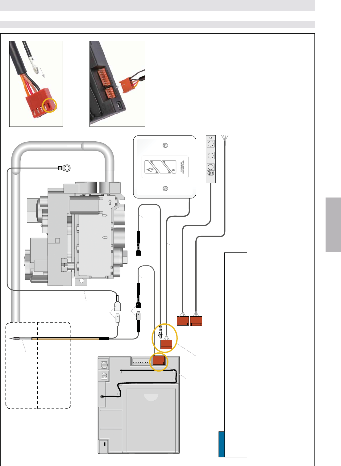
mis en route dans un certain laps de temps après ouverture.
et 1 minute après l’échec d’ouverture du gaz principal.
-
tionneront pas si le thermocouple est connecté.
ZCTCR/2000 est nécessaire pour utiliser l’interrupteur mural.
Association avec le tableau
pavé de touches G6R-CWSN.
connecteur de la prise (voir image 1). Un « clic » doit se faire entendre.
3. Insérer le réceptacle isolé dans le 2e terminal thermocouple isolé.
4. Insérer le connecteur dans le récepteur (voir image 2).
Figure 12
RF 2E OPTION DE THERMOCOUPLE (RF)
INSTRUCTIONS D’INSTALLATION UNIQUEMENT POUR UTILISATION SELON
LES DIRECTIVES DU FABRICANT
ON-OFF
UP
DOWN
2e thermocouple
G60-ZPT300
Câble 2e thermocouple
G60-ZCTC…
Câble 2e thermocouple
G60-ZCTCR…
Câble de connexion
pour combinaison avec
interrupteur mural
Connexion standard
Câble de mise
à la terre
G60-ZCGTC/…
Commutateur mural (en option)
Image 1: Fermer le contact à sertir MOLEX
(G60-ZCTCR…) à l’intérieur du trou du connecteur
de la prise.
Panneau de commande (en option)
Fonctionnement externe (en option)
Bloc gaz GV60
Câble isolé
Câble non-isolé
Image 2: Insérer le connecteur dans le récepteur.
Câble du commutateur mural/
pavé de touches G6R-CWSN
INDICATION
Récepteur
G6R-R3(4)AU..T
Brûleur principal
Brûleur pilote
(non représenté)
52 / 84
© 2014 Mertik Maxitrol GmbH & Co. KG, tous droits réservés.
FRANCAIS
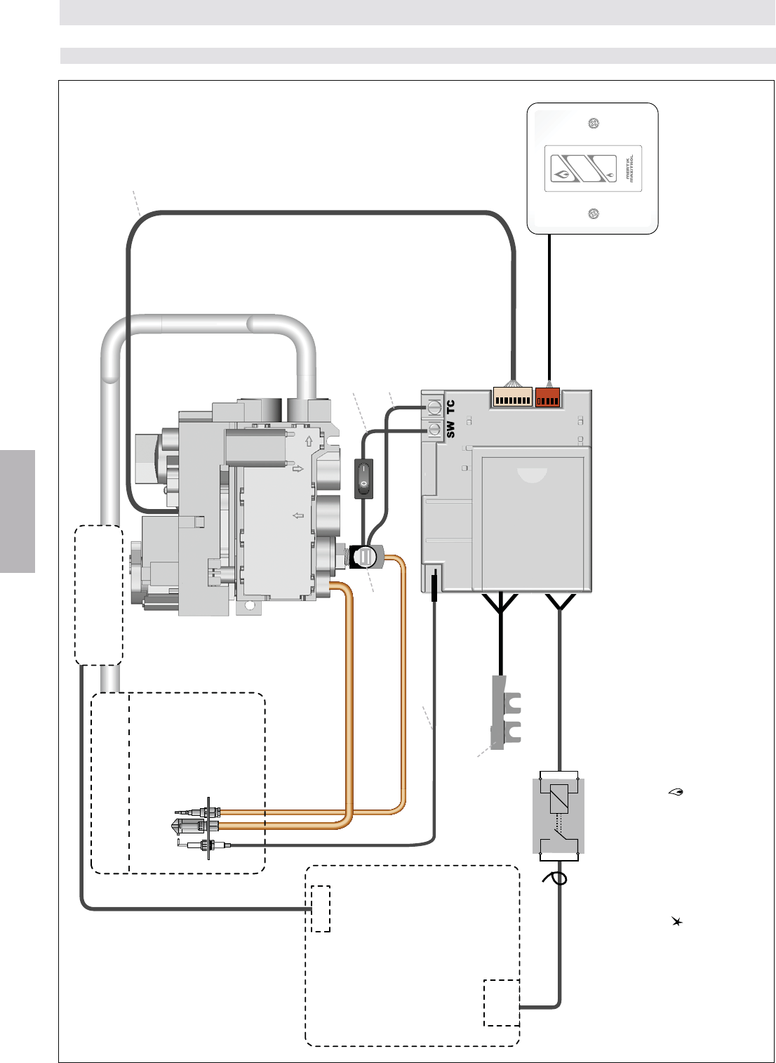
ON-OFF
UP
DOWN
Figure 13
DEMAR-
RAGE
Électrovanne
verrouillage
(Nécessité pour la
commande de VMC)
Capteur d’infrarouges
Commutateur mural
(en option)
VMC
(ventilation mécanique contrôlée)
(en option)
Récepteur
G6R-RIAE
Câble avec relais (en option)
G6R-CL...
Câble thermoélectrique SW
avec bouton ON/OFF
Câble thermoélectrique TC
Bloc interrupteur
Câble d’allumage
(étoile) et sur le bouton
-
il faut ajouter un commutateur supplémentaire au système pour éteindre le ventilateur.
INSTRUCTIONS D’INSTALLATION UNIQUEMENT POUR UTILISATION SELON
LES DIRECTIVES DU FABRICANT
INFRAROUGE (IR)
Brûleur principal
Brûleur pilote
Bloc gaz GV60
53 / 84
© 2014 Mertik Maxitrol GmbH & Co. KG, tous droits réservés.
FRANCAIS
Contact auxiliaire pour
commuter une charge
électrique ON/OFF.
INSTRUCTIONS D’INSTALLATION UNIQUEMENT POUR UTILISATION SELON
LES DIRECTIVES DU FABRICANT
Figure 14
FONCTION RELAIS (CONTACT LIBRE DE POTENTIEL) (RF, IR)
Fonction Télécommande
[\$];@*+^
G6R-H3(4)D15
G6R-H3(4)T16
G6R-H3(4)DV13
G6R-H3(4)TV14
*\\$$\_`"
#<$$&'$\$%{|% $$
#<$$&$\$%{|% $$
G6R-H3(4)D10
G6R-H3(4)T7
G6R-H3(4)DV11
G6R-H3(4)TV12
Récepteur
G6R-R3(4)AU
Câble avec relais
G6R-CD (50 V/0,6 A)
G6R-CDB (240 V/5 A)
Câble d‘allumage
Câble thermoélectrique SW
avec bouton ON/OFF
Câble thermoélectrique TC
Bloc interrupteur
(voir tableau pt. 1) ou se commande manuellement avec la télécommande (voir tableau pt. 2)
Décharge de traction, min. 30N,
nécessaire pour le câble G6R-CDB
(monté par l‘installateur)
Bloc gaz GV60
Brûleur principal
Brûleur pilote
54 / 84
© 2014 Mertik Maxitrol GmbH & Co. KG, tous droits réservés.
FRANCAIS
1. La vis d’ajustage est accessible par un trou dans le bouton
ON (MARCHE).
Figure 15: GV60, branchements et options d’ajustage
Ajustage de la pression de sortie
(Soupape d’étranglement CE seulement)
sortie du robinet. La prise de pression s’ouvre en tournant
la vis dans le sens des aiguilles d’une montre .
Le régulateur de pression ou la soupape d’étranglement
sont situés au-dessous du chapeau et ils sont acces sibles
2. Mettre le bouton MANUEL et le bouton de soupape princi-
ON (MARCHE).
3. Tourner la vis d’ajustage du régulateur de pression pour
La pression augmente en tournant la vis dans le sens des
aiguilles d’une montre (modèles de régulateur de
pression) ou elle se réduit en tournant la vis dans le sens
inverse des aiguilles d’une montre .
Côté sortie
Côté entrée
Bouton de
la soupape
principale Bouton MANUEL
Fond sortie
Fond entrée
Régulateur de pression ou
soupape d’étranglement
(commencer par débrancher)
Prise de pression
d’entrée Prise de pression
de sortie
Ajustage du gaz
de la veilleuse vis
(tourner avec un
tournevis)
Dispositif
magnétique
&+\%$$
Branchement
Allumeur piézo
Fiche 2.8 x 0.8 mm
NOTE: La pression du modèle de soupape d’étranglement est
augmentée en la tournant dans le sens inverse des
aiguilles d’une montre ou réduite en la tournant
dans le sens des aiguilles d’une montre .
5. Si aucun autre ajustage n’est nécessité, fermer la/les
prise(s) de pression en tournant le(s) vis complètement dans
le sens des aiguilles d’une montre
de fuite sur toutes les connexions/prise(s) de pression.
Figure 17: Commande de combinaison GV60, chapeau
Régulateur de pression ou soupape d’étranglement
INSTRUCTIONS D’INSTALLATION UNIQUEMENT POUR UTILISATION SELON
LES DIRECTIVES DU FABRICANT
réglage au-dessous.
4. Tourner la vis de réglage dans le sens des aiguilles d’une
montre pour réduire ou dans le sens inverse des
aiguilles d’une montre
la veilleuse.
Les boutons de commande du gaz fonctionnent comme suit
BOUTON POSITION FONCTION
Bouton de la soupape
principale OFF (ARRÊT) {$}!_`Q
travers la soupape.
Bouton de la soupape
principale
ON
(MARCHE)
<$_`Q
travers la soupape si la veilleuse est
allumée et si le thermocouple génère
+$$~\\
Bouton MANUEL MAN
Permet à la veilleuse d’être allumée
$$$}!_
gaz principal.
Bouton MANUEL ON
(MARCHE) Permet l’allumage automatique.
AJUSTAGE
AVERTISSEMENT
Ne pas essayer de démonter des vis du chapeau du bloc
signalisation anti-manipulation; le bouton du moteur ne
doit pas être démonté.
AVERTISSEMENT
PARAMÈTRES DU BOUTON
Dispositifs à gaz vides
"$$!$
>Q?
(10 à 13 mm)
Thermocouple
55 / 84
© 2014 Mertik Maxitrol GmbH & Co. KG, tous droits réservés.
FRANCAIS
Position NG
Bouchon de conversion gaz
Position LP
180°
obtenus en ajustant le bloc gaz, contrôler la pression
d’entrée sur le bloc gaz en utilisant un manomètre sur la
prise de pression de l’entrée du bloc gaz. Si la pression
d’entrée se trouve dans une gamme normale, remplacer
le bloc gaz; sinon, procéder aux étapes nécessaires pour
assurer la pression de gaz propre vers le bloc gaz.
(en option)
(NG) et celle pour le GPL (LP).
Pour passer du gaz naturel (NG) au GPL (LP) ou inversement,
inverse des aiguilles d’une montre et l’enlever.
Tourner le bouchon de conversion dans le sens complet des
NOTE: La vis sous la couleur de sécurité ne doit pas être
réglé.
INSTRUCTIONS D’INSTALLATION UNIQUEMENT POUR UTILISATION SELON
LES DIRECTIVES DU FABRICANT
le bouton du moteur dans la position OFF (ARRÊT), puis
s’ouvre.
2. Le niveau minimal peut être réglé soit en effectuant un
soit sur une vis de niveau minimal réglable. Les commandes
3. Tourner la vis dans le sens des aiguilles d’une montre
5. Fermer la/les prise(s) de pression en tournant complète-
ment la/les vis dans le sens des aiguilles d’une montre
prise(s) de pression.
pour répondre aux exigences du fabricant con cernant un type
du niveau minimal et du gaz de la veilleuse s’effectuent selon
les instructions mentionnées ci-dessus. Pour convertir au GPL
la limite du bas (ou en tournant complètement la vis d’ajustage
CONTRÔLE FINAL
une exploitation correcte. Pendant ces cycles, le système
optimal d’allumage.
1. STOP! Lire les informations de sécurité ci-jointes avant
d’agir.
2. Tourner le bouton de la soupape principale en position OFF
(ARRÊT) , dans le sens complet des aiguilles d’une
montre.
3. Mettre le bouton ON/OFF (MARCHE/ARRÊT), si dans
O (ARRÊT).
y compris au niveau du sol. Si vous détectez du gaz,
ARRETEZ l’installation ! Observer la rubrique «QUE
FAIRE EN CAS D’ODEUR DE GAZ» aux informations
de sécurité (page 24). Si aucun gaz n’est présent, veuillez
procéder selon les instructions de service Mertik Maxitrol
pour l’installation.
AVERTISSEMENT
mages matériels, des blessures graves, ou la mort. Ne pas
démonter le bloc gaz; il ne contient aucuns composants
Figure 18: Conversion entre gaz naturel et GPL
Bouchon de conversion gaz
56 / 84
© 2014 Mertik Maxitrol GmbH & Co. KG, tous droits réservés.
FRANCAIS
INDICATION
INDICATION
INDICATION
NOTES GENERALES
avant de démarrer l’allumage. Tout non-respect peut
Télécommande Fréquence Radio
433,92 MHz pour l’Europe; 315 MHz pour les Etats-Unis (code
FCC:RTD-G6R) et pour le Canada (IC: 4943A-G6R).
L’exploitation doit s’effectuer obligatoirement dans les deux
d’interférences importantes, et (2) Cet appareil doit accepter
non approuvées expressément par la partie responsable
Piles – télécommande
écran
Piles – récepteur
-
l’éclairage/variateur comprennent ensemble une alimenta-
en cas de panne de tension.
Figure 20: Télécommande précédente
Les télécommande, récepteurs, les commutateurs muraux,
les panneaux de commandes et les pavés de touche ne
peuvent pas être remplacés par les dispositifs électro-
Figure 21: Bouton de
réinitia lisation du récepteur
Télécommande Fréquence radio
aléatoires de disponibles. Le récepteur doit apprendre le code
de la télécommande:
est plus court et le second bip plus long. Après le second
incorrect.
NOTE:
le remplacement des piles dans la télécommande
ou le récepteur.
INSTRUCTIONS DE SERVICE UNIQUEMENT POUR UTILISATION SELON
LES DIRECTIVES DU FABRICANT
INDICATION
Seul l’adaptateur principal Mertik Maxitrol AC ou un
approuvé préalablement par Mertik Maxitrol peuvent être
utilisés. L’utilisation d’autres adaptateurs peut empêcher
le fonctionnement du système.
Fonction Eclairage/
variateur activée (page 58)
Ventilation active (page 58)
Changement de la programma-
tion des horloges (page 60)
Température
ou °F/12 heures (page 59)
Indicateur de niveau de ventilation (page 58)
Electrovanne brûleur,
ouverture/fermeture (page 58)
ON/OFF (page 59)
Indicateur de signal
Modes de fonctionnement (page 58)
Figure 19
PARAMÈTRES DU CODE ÉLECTRONIQUE
Les télécommandes en rechange des modèles CSA
doivent porter le même numéro de référence (voir éti-
57 / 84
© 2014 Mertik Maxitrol GmbH & Co. KG, tous droits réservés.
FRANCAIS
Figure 22: Panneau de commande et commutateur mural/pavé de touches
Commutateur mural/pavé de touches/
panneau de commande
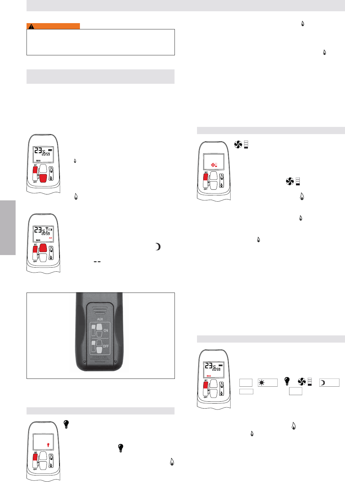
Appuyer et maintenir enfoncé le bouton A pour augmenter
Appuyer et maintenir enfoncé le bouton C pour réduire la
de veilleuse.
MAN
C
(petite
NOTE:
-
gnée.
MAN
C
(grande
-
AVERTISSEMENT
ALLUMER L’APPAREIL
ON (MARCHE)
, dans le sens inverse complet des aiguilles d’une
montre
ON/OFF (MARCHE/ARRÊT), si dans
sur le I (MARCHE).
Télécommande
Appuyer simultanément sur les boutons OFF
et
La poursuite des bips c -
mage est en cours.
Après l’allumage du brûleur principal,la
mode manuel (version CSA, version CE).
Commutateur mural/pavé de touches/
panneau de commande
gaz principal.
AVERTISSEMENT
Si la veilleuse ne reste pas allumée après plusieurs essais,
mettre le bouton de la soupape principale en position
OFFARRÊTER
L’ALIMENTATION EN GAZ VERS L’APPAREIL» (page 61).
Télécommande
Appuyer et maintenir enfoncé
Commutateur mural/pavé de touches/
panneau de commande
ARRÊTER L’APPAREIL
Télécommande
Appuyer sur le bouton OFF.
Commutateur mural/pavé de touches/
panneau de commande
AJUSTAGE DE LA HAUTEUR DE FLAMME
Télécommande
En mode de veille: appuyer et maintenir
enfoncé le bouton
(petite
veilleuse.
INSTRUCTIONS DE SERVICE UNIQUEMENT POUR UTILISATION SELON
LES DIRECTIVES DU FABRICANT
A) Augmenter la hauteur
$$
B) MARCHE/ARRÊT
C) Réduire la hauteur
$$
58 / 84
© 2014 Mertik Maxitrol GmbH & Co. KG, tous droits réservés.
FRANCAIS
AVERTISSEMENT
Si l’installation ne fonctionne pas, suivre les instructions de
ARRÊTER L’ALIMENTATION EN GAZ VERS
L’APPAREIL» (page 61).
POUR OUVRIR ET FERMER L’ÉLECTROVANNE/LE
BRÛLEUR
NOTE: L’électrovanne ne peut pas fonctionner manuellement.
de fonctionnement. Pendant le fonctionnement nor-
principal et le brûleur décoratif sont sur ON.
Appuyer simultanément sur les boutons SET
et
en position OFF. Les instructions imprimées
se trouvent sur le couvercle du compartiment
et
OUVERTE.)
NOTE: Le fonctionnement de la fonction AUX
tem-
pérature de remise en heure de nuit
est “ ”.
Figure 23: Instructions relatives à l‘électrovanne (sur le couvercle du compartiment
à piles)
FONCTIONNEMENT ÉCLAIRAGE/VARIATEUR
naviguer au mode (ampoule). L’icône
d’ampoule clignote.
ou augmenter la clarté.
pour réduire la clarté.
l’éclairage. Si vous voulez ALLUMER l’éclairage mais sans
(basse
NOTE:
réglage du mode éclairage/variateur. 8 se condes
après le réglage de l’éclairage/variateur, la télécom-
-
mande de température (version CSA) ou au mode
manuel (version CE).
FONCTIONNEMENT DU VENTILATEUR CIRCULANT
– Ventilateur circulant
Le ventilateur circulant a 4 niveaux de vitesse
naviguer au mode (ventilateur). Les
icônes de ventilateur et de niveau clignotent.
pour ALLUMER et augmenter la vitesse du
ventilateur.
pour réduire la vitesse du venti lateur. Pour
ARRETER le ventilateur, appuyer sur le
bouton
4 barres de niveau disparaissent.
NOTE: 8 secondes après le réglage du ventilateur, la
de commande de température (version CSA) ou au
mode manuel (version CE). Le ventilateur démarre
4 minutes après l’ouverture du gaz (de OFF ou de
ou en veilleuse.
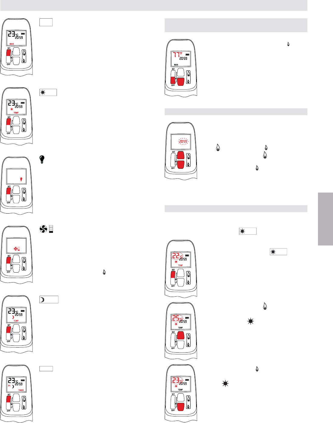
MODES DE FONCTIONNEMENT
l’ordre suivant:
MAN
TEMP
TEMP
TIMER
MAN
.
NOTE: Il est également possible d’accéder au mode manuel
en appuyant soit sur le bouton
sur le bouton
Brûleur ARRÊT
INSTRUCTIONS DE SERVICE UNIQUEMENT POUR UTILISATION SELON
LES DIRECTIVES DU FABRICANT
Brûleur MARCHE
59 / 84
© 2014 Mertik Maxitrol GmbH & Co. KG, tous droits réservés.
FRANCAIS
MAN
– Mode manuel
TEMP
– Mode de température en heure
de jour (l’installation doit être en mode de
veille; veilleuse allumée)
La température ambiante est mesurée et
-
-
heure de jour.
– Mode de réglage éclairage/variateur
ALLUMER et ETEINDRE l’éclairage/varia-
teur et ajuster la clarté.
– Mode de paramétrage du ventila-
teur circulant
ALLUME et ETEINT le ventilateur circulant
et ajuste la vitesse du ventilateur.
NOTE: Pour ARRETER le ventilateur, ap-
puyer sur le bouton
disparaissent.
TEMP
– Mode de température de remise
en heure de nuit (l’installation doit être en
mode de veille; veilleuse allumée)
La température ambiante est mesurée et
la température de remise en heure de nuit.
TIMER
– Mode d’horloge (L’installation doit
être en mode de veille; veilleuse allumée)
Les horloges P1 et P2 (programme 1,
programme 2) peuvent être programmés
chacun pour s’ALLUMER et s’ETEINDRE
-
tions, consulteur le mode de programmation
d’horloge.
NOTE: L’écran affiche la température réglée toutes les
30 secondes.
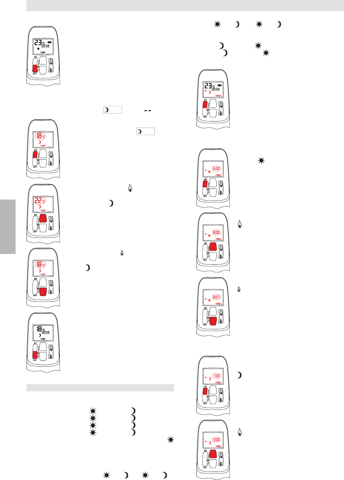
PARAMÈTRE HORLOGE °C/24 HEURES
OU °F/12 HEURES
OFF et (petite
Celsius/24 heures et inversement.
RÉGLAGE DE L’HEURE
a. l’installation de la pile, soit
b. en appuyant simultanément sur les bou-
tons
pour régler l’heure.
régler les minutes.
OFF ou attendre simplement
pour retourner au mode manuel.
CONFIGURATION DES TEMPÉRATURES ON/OFF
PARAMETRES PAR DEFAUT:
TEMP
(soleil),
23 °C/74 °F
naviguer au mode TEMP
TEMP
(soleil).
pour augmenter la température de réglage
de l’heure du jour .
réduire la température de réglage de l’heure
du jour .
INSTRUCTIONS DE SERVICE UNIQUEMENT POUR UTILISATION SELON
LES DIRECTIVES DU FABRICANT
60 / 84
© 2014 Mertik Maxitrol GmbH & Co. KG, tous droits réservés.
FRANCAIS
= P1 ou P2 = P2 , l’horloge est désactivée.
comme suit:
CE: P2 23:50 et P1 0:00
CSA: P2 11:50pm et P1 12:00am
seulement si le module est connecté
Sélectionner le mode d’horloge en appuyant
brièvement sur le bouton SET.
Réglage P1 heure ALLUMEE
clignote.
Réglage P1 heure ETEINTE
naviguer au mode P1 heure ETEINTE. P1
pour terminer la programmation.
Réglage de la «REMISE EN HEURE DE NUIT» Température
PARAMETRES PAR DEFAUT:
TEMP
(lune), « » (OFF)
naviguer au mode TEMP
TEMP
(lune).
Appuyer sur le bouton
pour augmenter la température de remise
en heure de nuit .
réduire la température de remise en heure
de nuit .
pour terminer la programmation.
RÉGLAGE DU PROGRAMME DES HORLOGES
Parametres par Defaut
CE: Programme 1: P1 : 6h:0 P1 : 8:00
Programme 2: P2
: 23:50 P2 : 23:50
CSA: Programme 1: P1 : 6:00am P1 : 8:00am
Programme 2: P2 : 23:50pm P2 : 11:50pm
par jour.
ampm
-
mées dans l’ordre suivant: P1
< P2
.
INSTRUCTIONS DE SERVICE UNIQUEMENT POUR UTILISATION SELON
LES DIRECTIVES DU FABRICANT
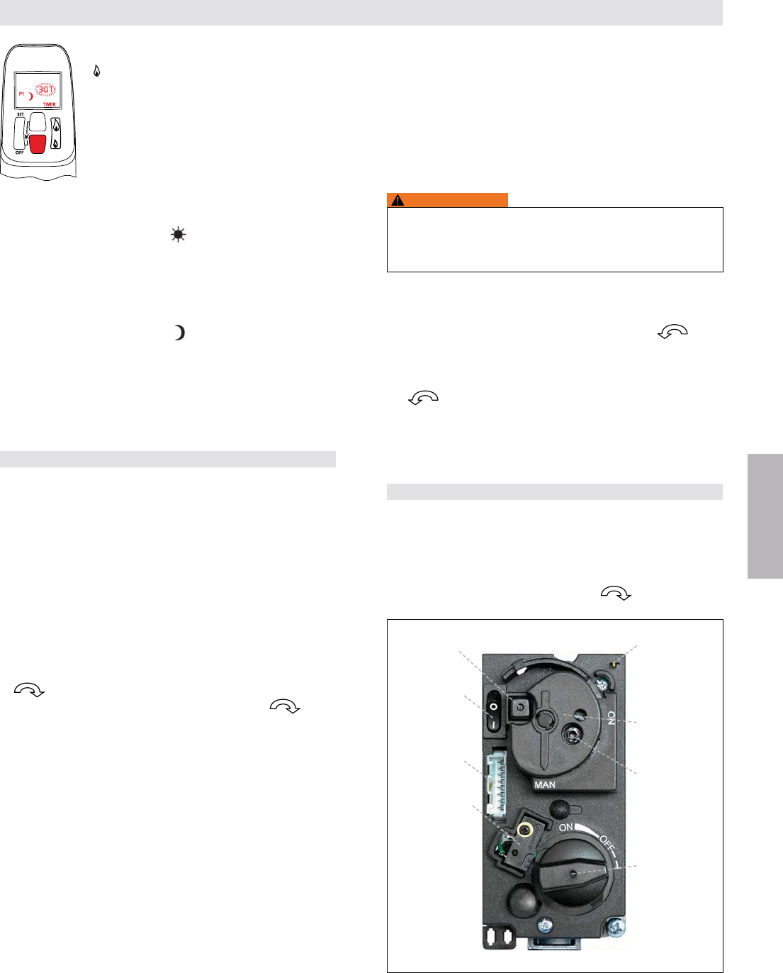
61 / 84
© 2014 Mertik Maxitrol GmbH & Co. KG, tous droits réservés.
FRANCAIS
Réglage P2 heure ALLUMEE
Appuyer brièvement sur le bouton SET pour naviguer au
mode P2 heure ETEINTE. P2
clignote.
Voir les instructions REGLAGE P2 HEURE ALLUMEE.
Réglage P2 heure ETEINTE
Appuyer brièvement sur le bouton SET pour naviguer au
mode P2 heure ETEINTE. P2
clignote.
Voir les instructions REGLAGE P2 HEURE ETEINTE.
La présente partie termine la programmation des horloges
P1 et P2. Appuyer sur le bouton OFF. La télécommande
FONCTIONNEMENT MANUEL
en cas d’allumage avec une allumette.
En tournant le bouton de la soupape principale, ne pas forcer.
les arrêts d’extrémité soient atteints. Ceci permet un ajustage
position de veille de la veilleuse.
1. STOP! Lire les informations de sécurité ci-jointes avant
d’agir.
2. Tourner le bouton de la soupape principale en position OFF
, dans le sens complet des aiguilles d’une montre.
3. Tourner le bouton MANUEL en position MAN , dans
le sens complet des aiguilles d’une montre.
O
(position OFF).
y compris au niveau du sol. Si vous détectez du gaz,
ARRETEZ l’installation ! Observer la rubrique «QUE
FAIRE EN CAS D’ODEUR DE GAZ?» aux informations
de sécurité à la page 43. Si aucun gaz n’est présent,
I
(position ON).
7. Le bouton MANUEL en position MAN permet d’accéder
8. Enfoncer complètement l’élément de manoeuvre manuelle
de la soupape de veilleuse en le gardant enfoncé pour
Allumage avec une allumette:
Allumer immédiatement la veilleuse avec une allumette en
continuant de maintenir l’élément de manoeuvre manuelle
de la soupape de veilleuse pendant environ une (1) minute
de manoeuvre manuelle de la soupape de veilleuse. Si la
répéter l’opération.
Allumage avec allumeur piézo:
et répéter l’opération.
AVERTISSEMENT
Si la veilleuse ne reste pas allumée après plusieurs
essais, mettre le bouton de la soupape principale en posi-
tion OFF
9. Si cette opération est applicable, remplacer le panneau
10. Tourner le bouton MANUEL en position ON , dans
le sens inverse complet des aiguilles d’une montre.
11. Tourner bouton de la soupape principale en position ON,
dans le sens inverse complet des aiguilles d’une montre
.
12. Si l’installation ne fonctionne pas, suivre les instructions
ARRÊTER L’ALIMENTATION EN GAZ
VERS L’INSTALLATION».
ARRÊTER L’ALIMENTATION EN GAZ VERS L’APPAREIL
O
(position OFF).
2. Si la commande de gaz est accessible, tourner le bouton
de la soupape principale en position OFF, dans le sens
complet des aiguilles d’une montre .
INSTRUCTIONS DE SERVICE UNIQUEMENT POUR UTILISATION SELON
LES DIRECTIVES DU FABRICANT
Figure 24: Bloc gaz GV60, chapeau
Allumeur piézo
(en option)
Bouton ON/OFF
(en option) en
position ON
Prise récepteur
Y+
Microcommutateur
Branchement
Allumeur
piézo Fiche
2.8 x 0.8 mm
Bouton MANUEL
en position MAN
Elément de
manoeuvre
manuelle
soupape de
veilleuse
Bouton de
la soupape
principale en
position OFF

62 / 84
© 2014 Mertik Maxitrol GmbH & Co. KG, tous droits réservés.
FRANCAIS
MISE AU REPOS AUTOMATIQUE
6 heures sans fonction de communication
(version CSA)
6 heures. Au mode température/horloge, si la température
-
rature réglée et la température ambiante de la pièce restent
Surchauffe du récepteur
-
1 heure d’arrêt pour les récepteurs spéciaux
-
de 1 heure.
ARRET AUTOMATIQUE
Recepteur de pile dechargee
Avec une basse puissance de pile dans le récepteur, le
Arrêt cinq jours
(version CSA)
Le système arrête complètement le feu si aucun changement
Arrêt du second thermocouple
(en option)
Option du second thermocouple: Le système arrête le feu si
le brûleur principal ne s’allume pas complètement environ
20 secondes après l’allumage ou après avoir appuyé sur le
bouton
NOTE: Avant l’allumage suivant, il y a une période d’attente de
2 minutes. Si le thermocouple est encore trop chaud,
vous entendrez un bip long.
INSTRUCTIONS DE SERVICE UNIQUEMENT POUR UTILISATION SELON
LES DIRECTIVES DU FABRICANT

63 / 84
© 2014 Mertik Maxitrol GmbH & Co. KG, tous droits réservés.
FRANCAIS
R R
Exclusive Distributor North America
for Mertik Maxitrol
Maxitrol Company, Inc.
23555 Telegraph Rd., PO Box 2230
Southfield, MI 48037-2230
USA
Tel: +1 248-356-1400
Fax: +1 248-356-0829
www.maxitrol.com
Exclusive Distributor Europe
for Maxitrol Company
Mertik Maxitrol GmbH & Co. KG
Warnstedter Str. 3
06502 Thale
Germany
Tel: + 49 3947 400-0
Fax: + 49 3947 400-200
www.mertikmaxitrol.com
GV60-B-II.OI-EN-12.2014
© 2014 Mertik Maxitrol GmbH & Co. KG, All Rights Reserved./Alle Rechte vorbehalten./Tous droits réservés./Alle rechten voorbehouden.