Meru Networks AP150 Wireless Access Point (Dual Radio Version) User Manual AP Install
Meru Networks Inc. Wireless Access Point (Dual Radio Version) AP Install
UserManual.wiki
>
Meru Networks
>
AP150 User Manual
>
users manual
Contents
1.
users manual
2.
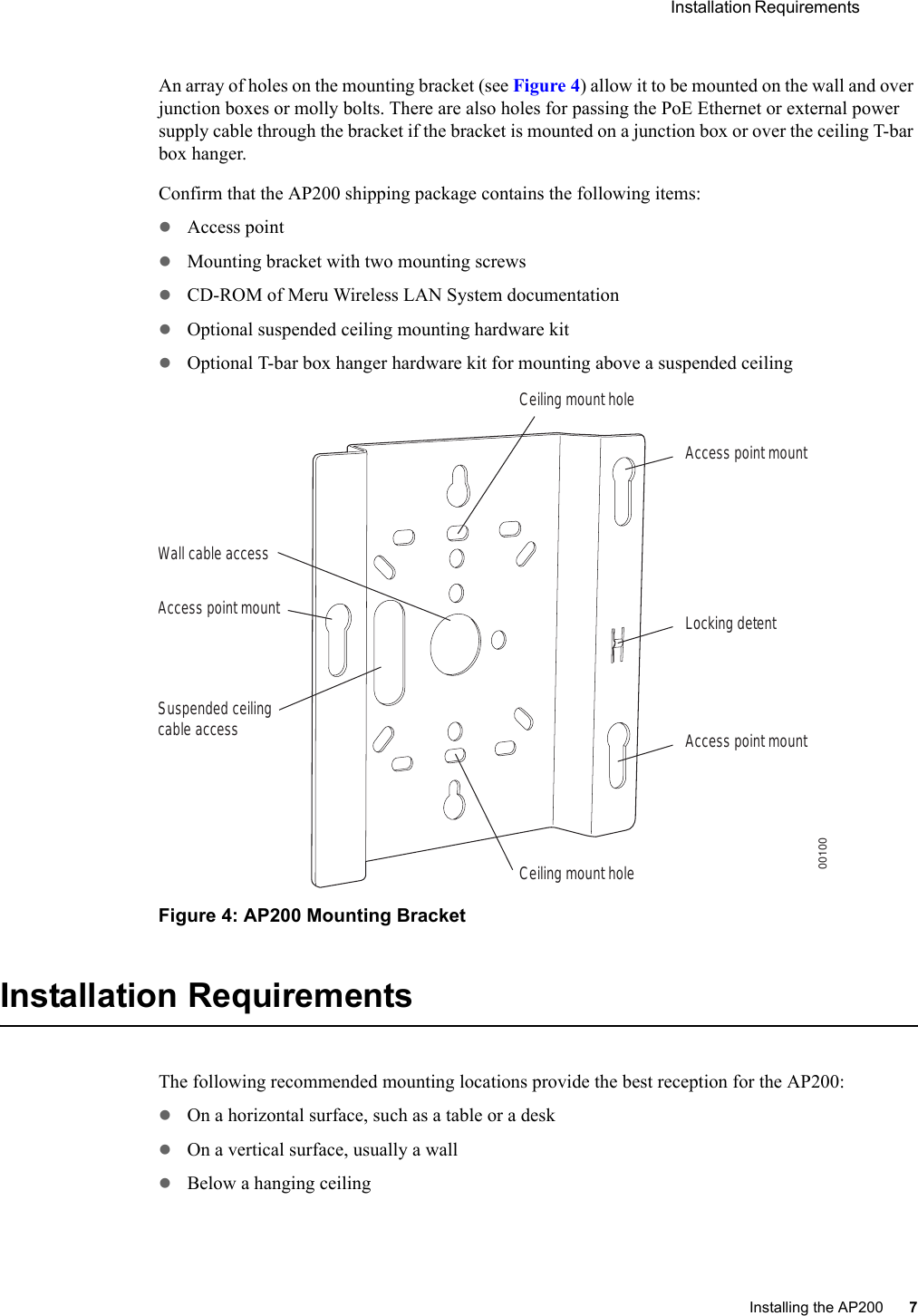
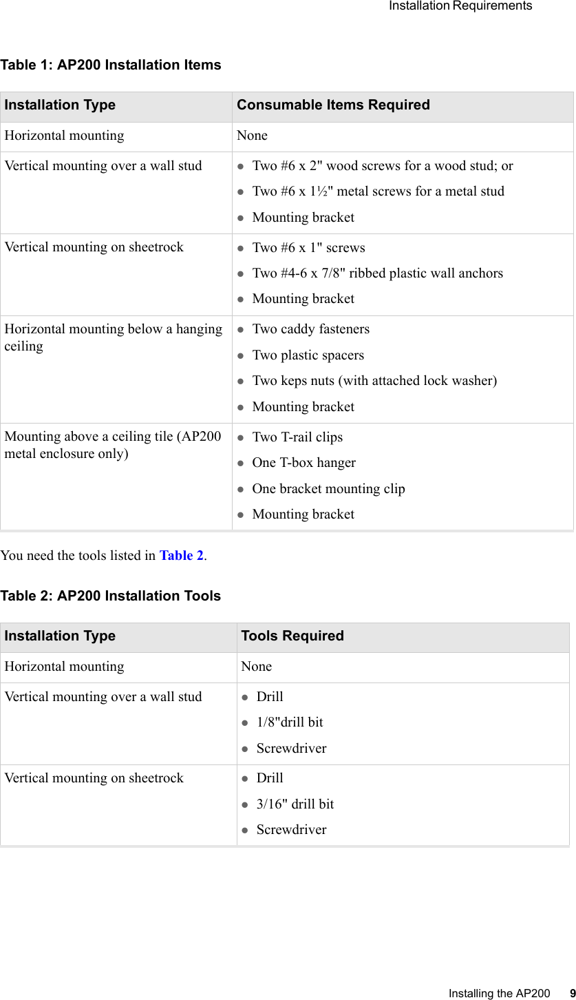
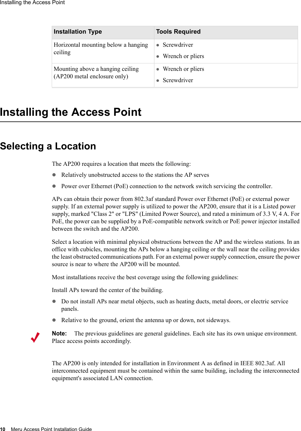
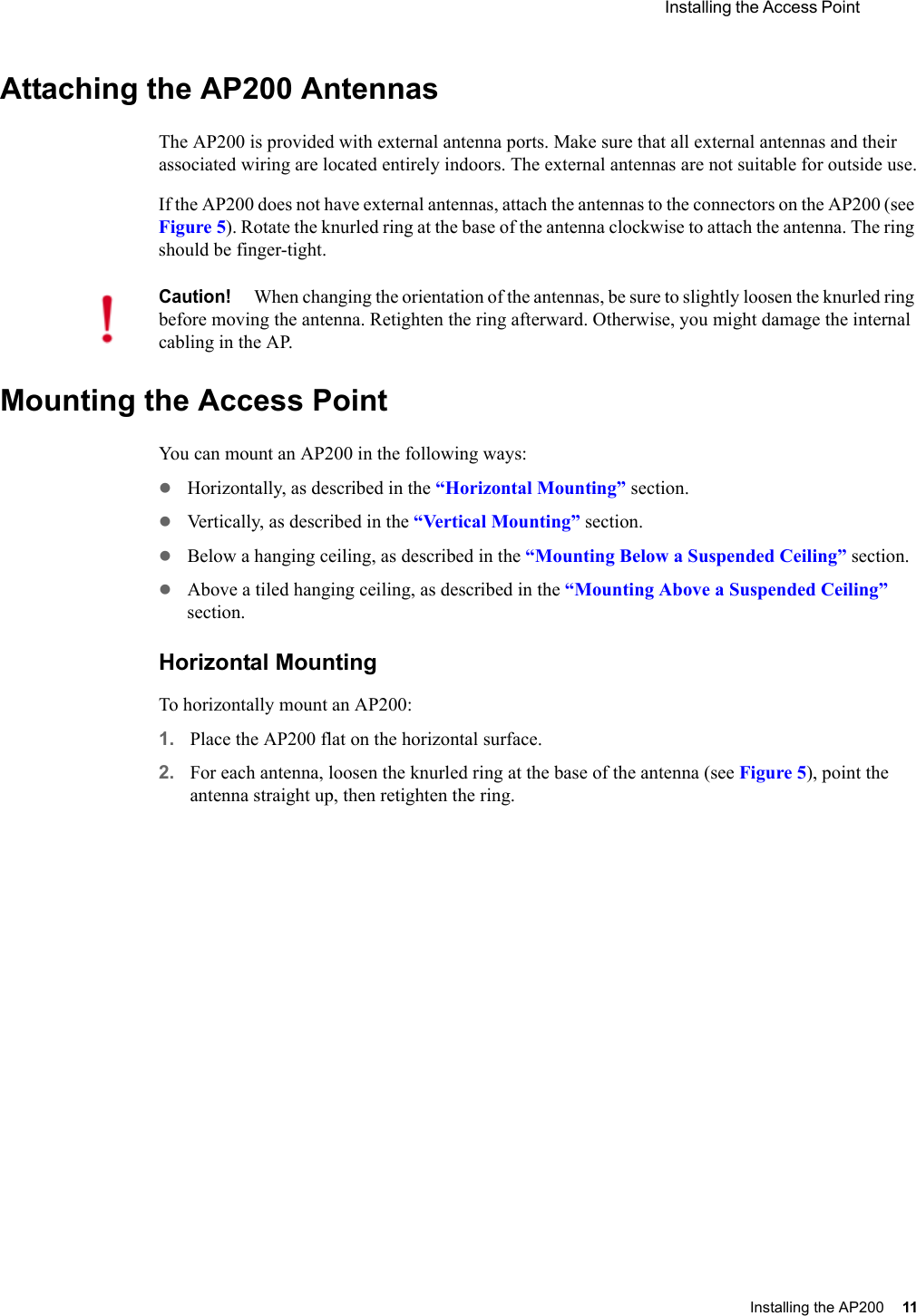
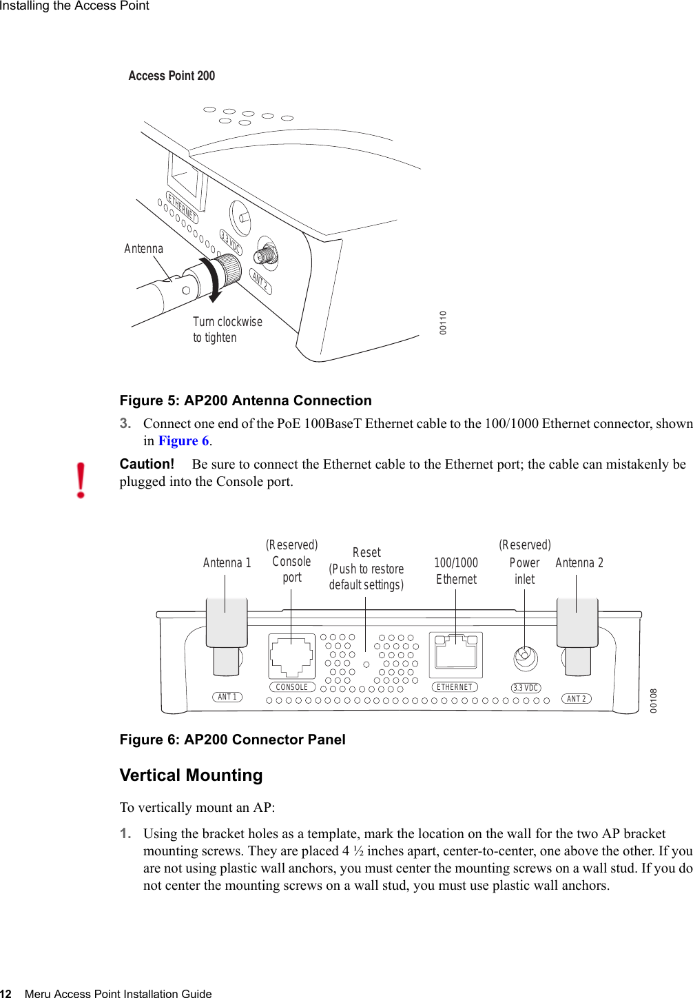
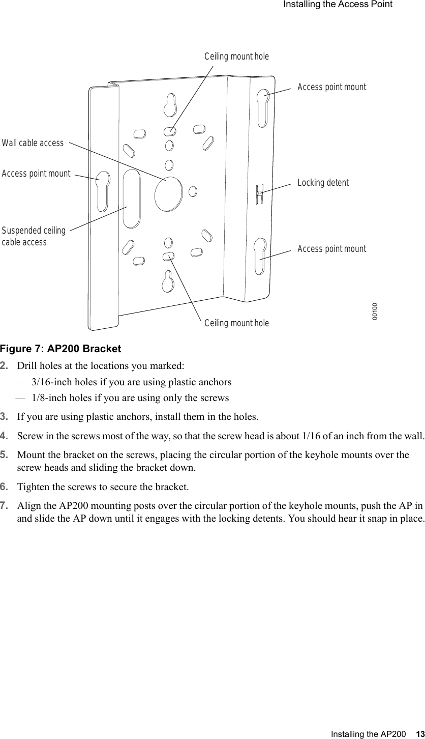
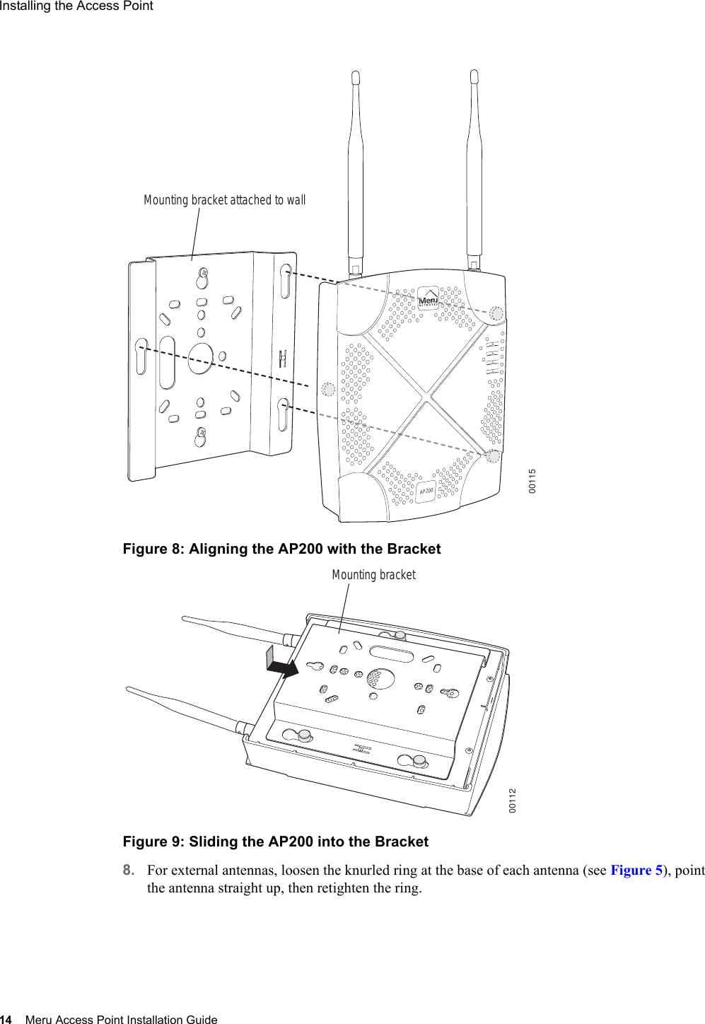
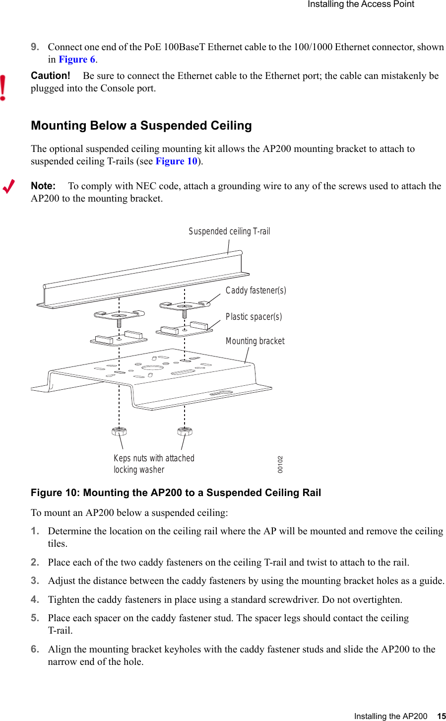
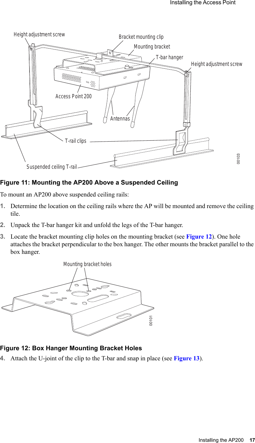
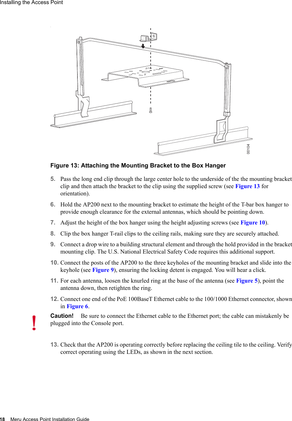
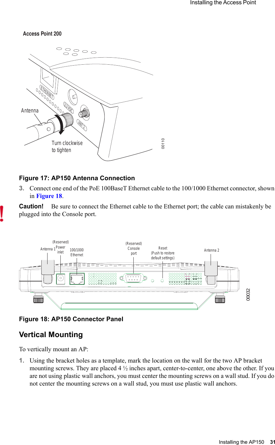
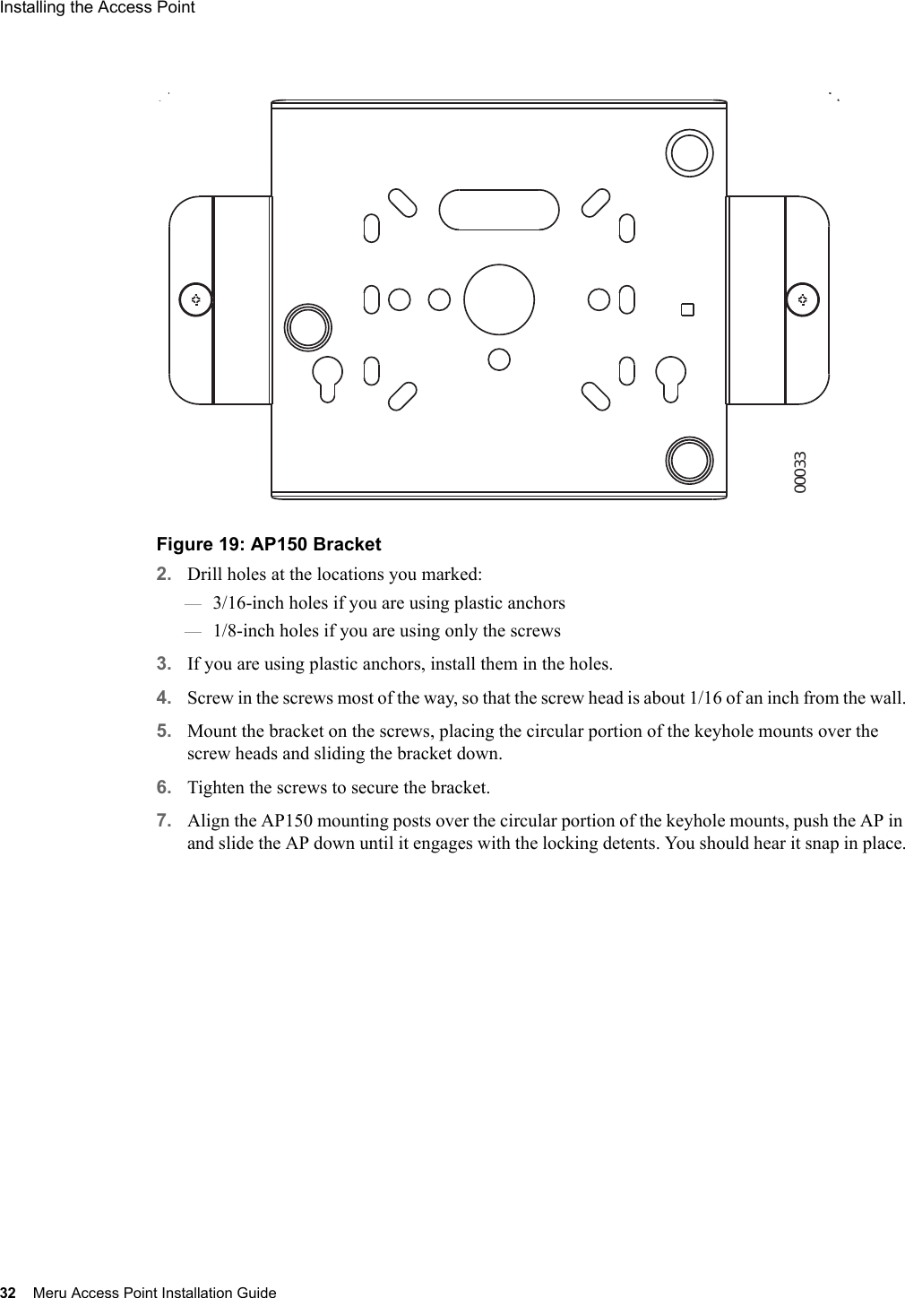
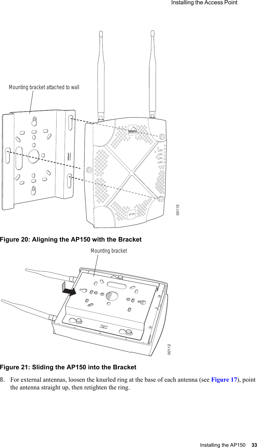
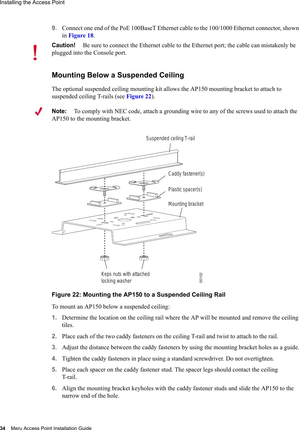
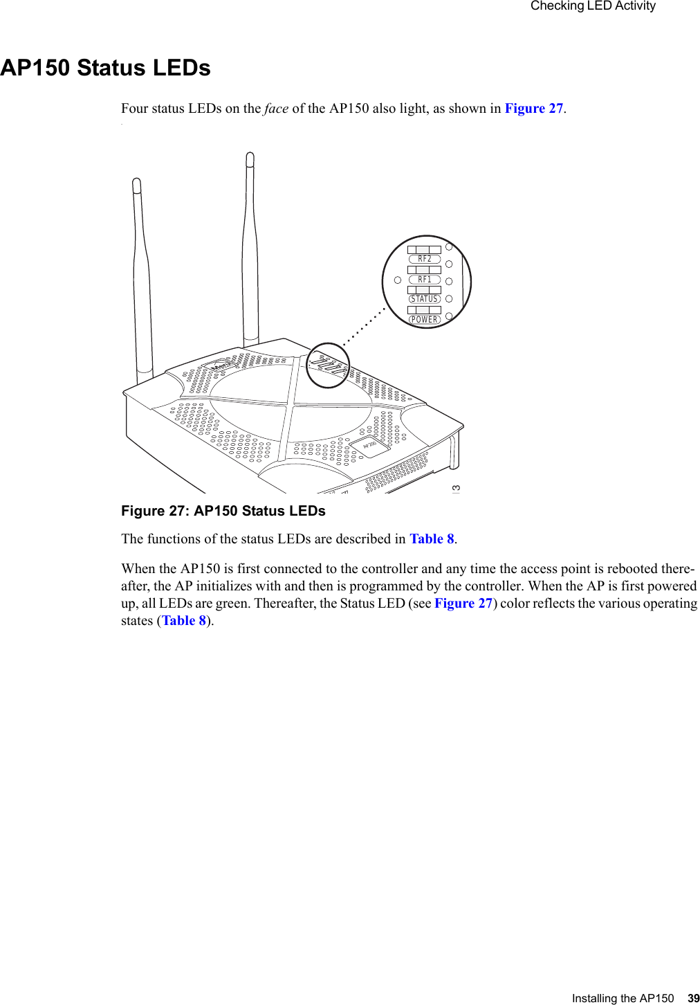
Installation Guide
users manual
Navigation menu
Upload a User Manual
Namespaces
Wiki Guide
HTML
PDF
Info
Views
User Manual
Discussion / Help
Navigation

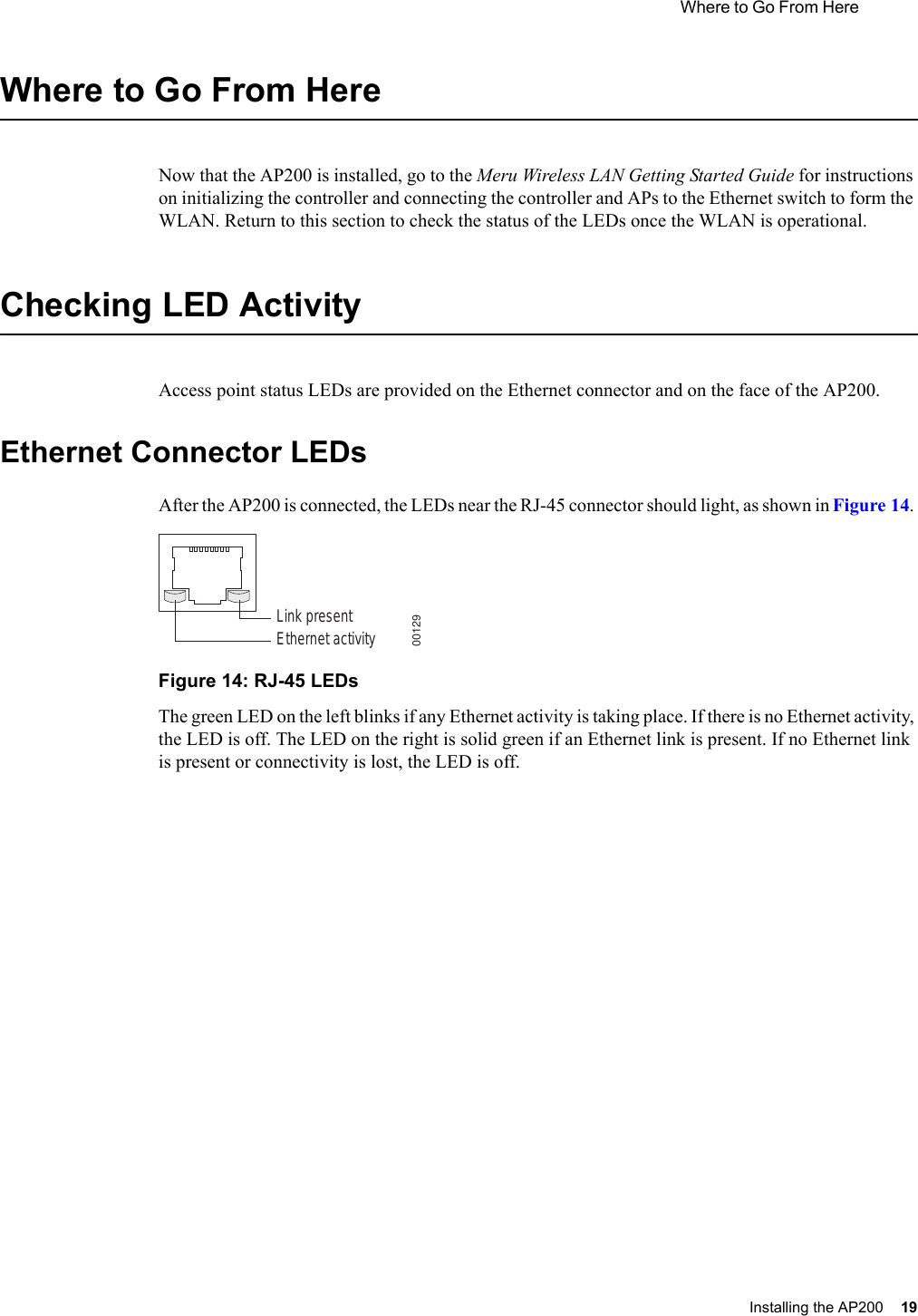
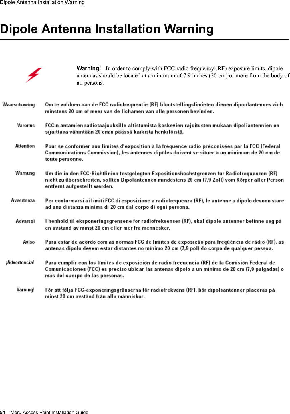
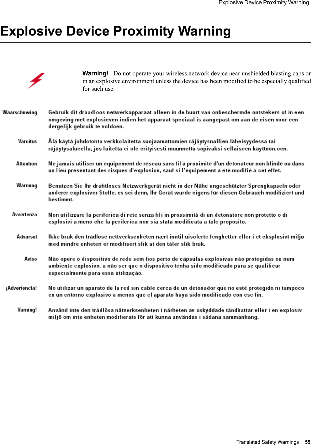
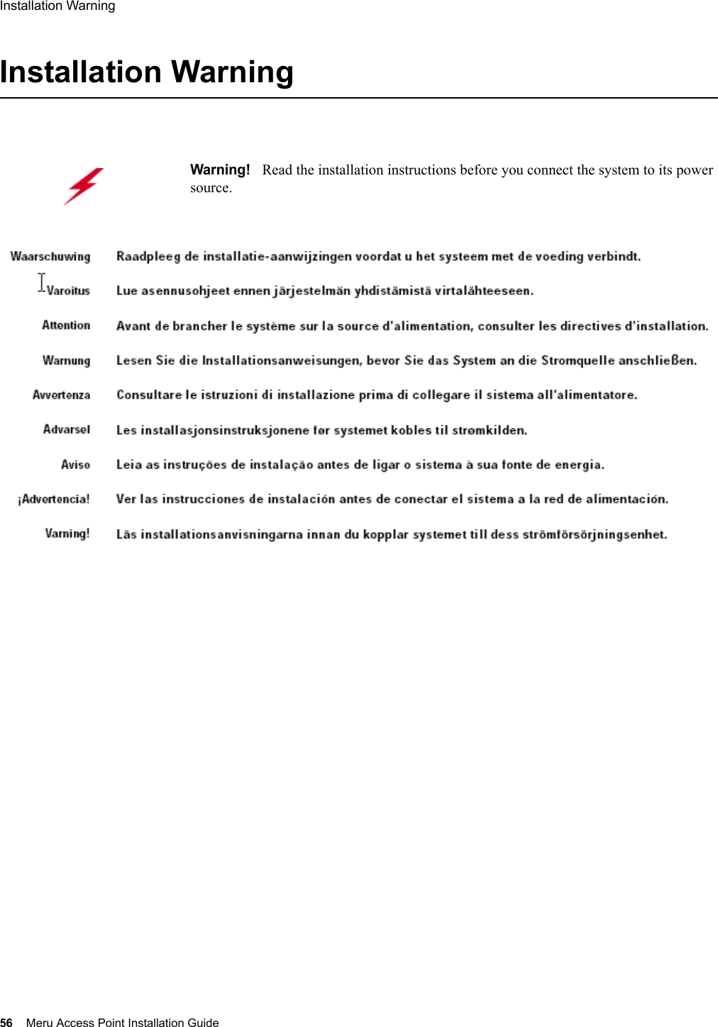
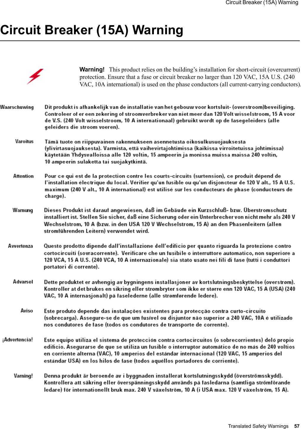
![Federal Communications Commission (FCC) Declaration of Conformity (DoC) & Instructions Regulatory Information 49 We, the responsible party, Meru Networks Inc., declare that the above-listed product, Wireless Access Point AP200 Rev. 2 Model Nos. 202 & 209, was tested to conform to the applicable FCC Rules and regulations. The method of testing was in accordance to the most accurate measurement standards possible, and that all necessary steps have been enforced to assure that all production units of the same equipment will continue to comply with the Federal Communications Commission’s requirements.Issue Date: [TBD]Srinath Sarang VP, Product ManagementInstructionsWarnings This equipment generates, uses, and can radiate radio frequency energy. If not installed and used in accordance with the instructions, these products may cause harmful interference to radio communications. However, there is no guarantee that interference will not occur in a particular installation. If this equipment does cause harmful interference to radio or television reception, which can be determined by turning the equipment off and on, the user is encouraged to try and correct the interference by one or more of the following measures: 1. Reorient or relocate the receiving antenna.2. Increase the distance between the equipment and the receiver. 3. Connect the equipment to an AC outlet on a circuit different from that to which the receiver is connected. 4. Consult the dealer or an experienced radio/TV technician for help. Address 1309 S. Mary Ave. Sunnyvale, CA 94087Contact Person/Title Mohammad Sa-id Senior Regulatory Compliance Manager Phone - (408) 215-5300 Fax - (408) 215-5301EUT Certification SummaryEquipment Class Class BReport References [TBD] Issue Date [TBD] Tested by Bay Area Compliance LabCompany Information](https://usermanual.wiki/Meru-Networks/AP150.users-manual/User-Guide-620290-Page-61.png)