Meru Networks OAP180R2 Outdoor Access Point, Model OAP-180 User Manual AP Install
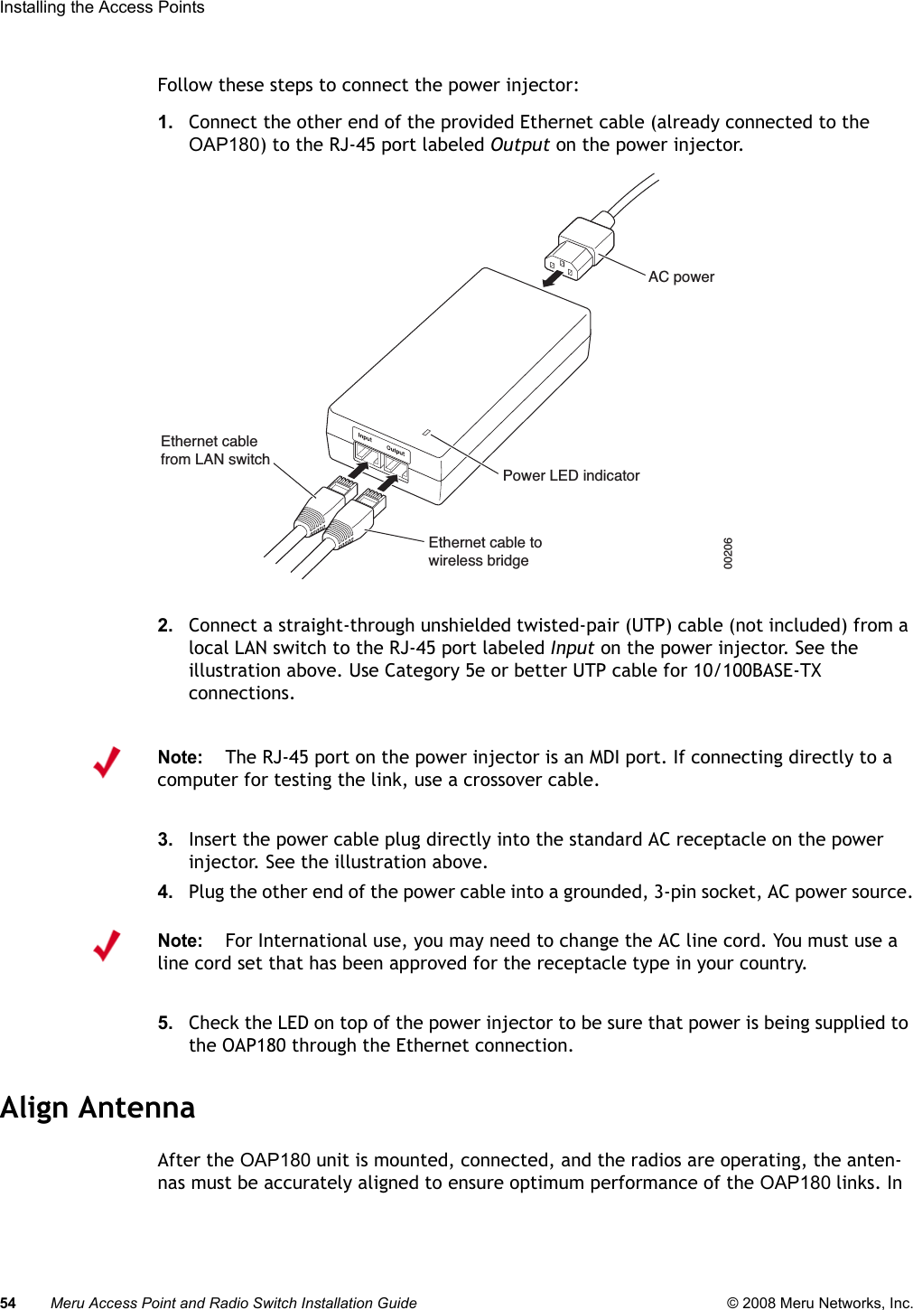
Meru Networks Inc. Outdoor Access Point, Model OAP-180 AP Install
UserManual.wiki
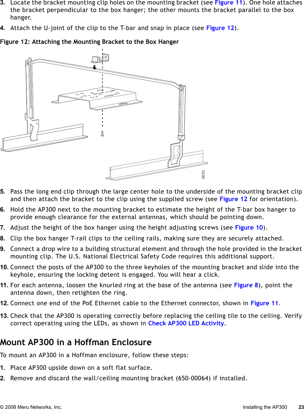
>
Meru Networks
>
OAP180R2 User Manual
User Manual
Navigation menu
Upload a User Manual
Namespaces
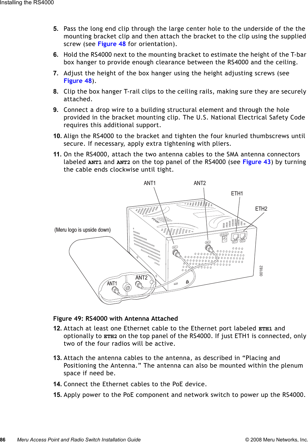
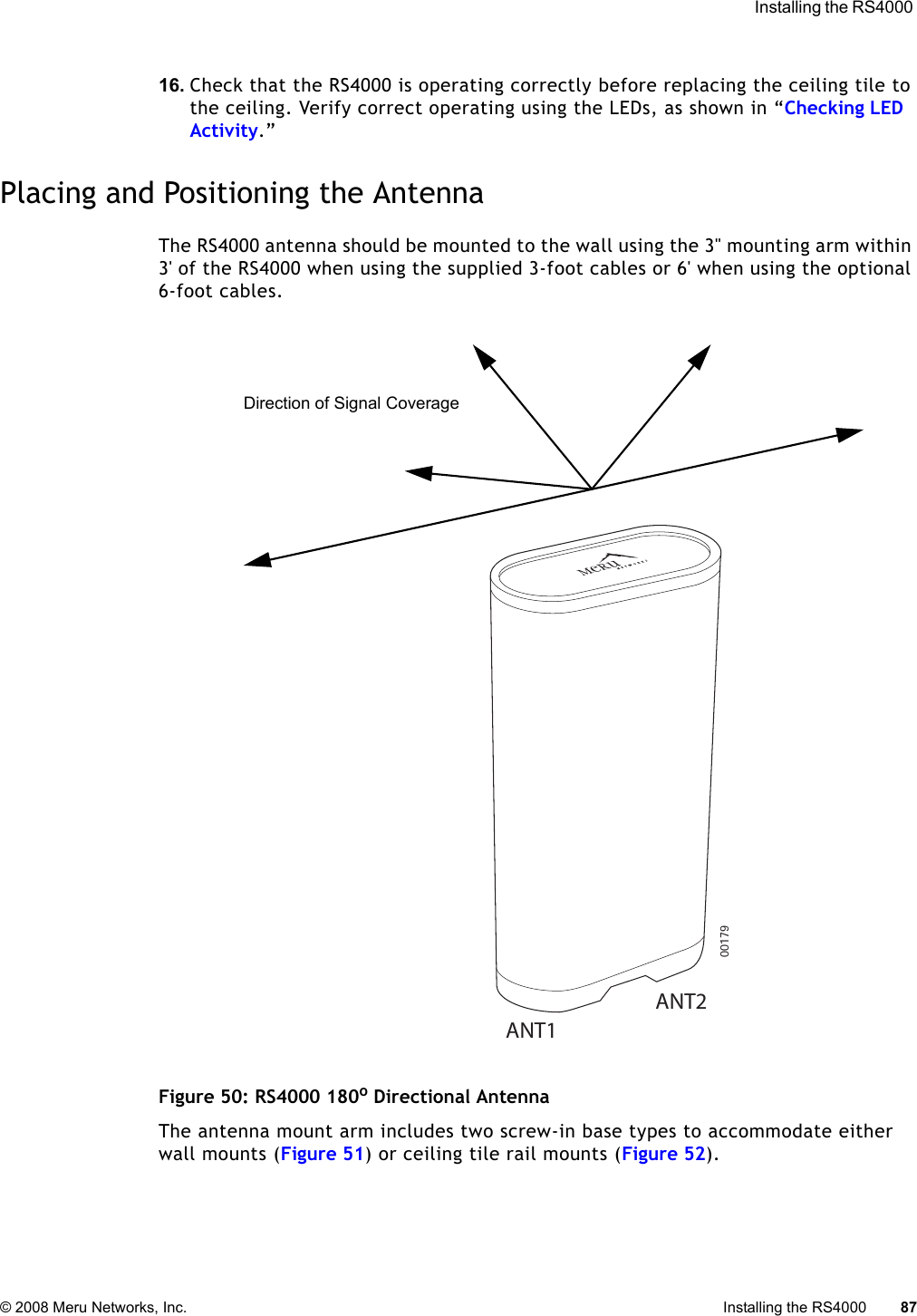
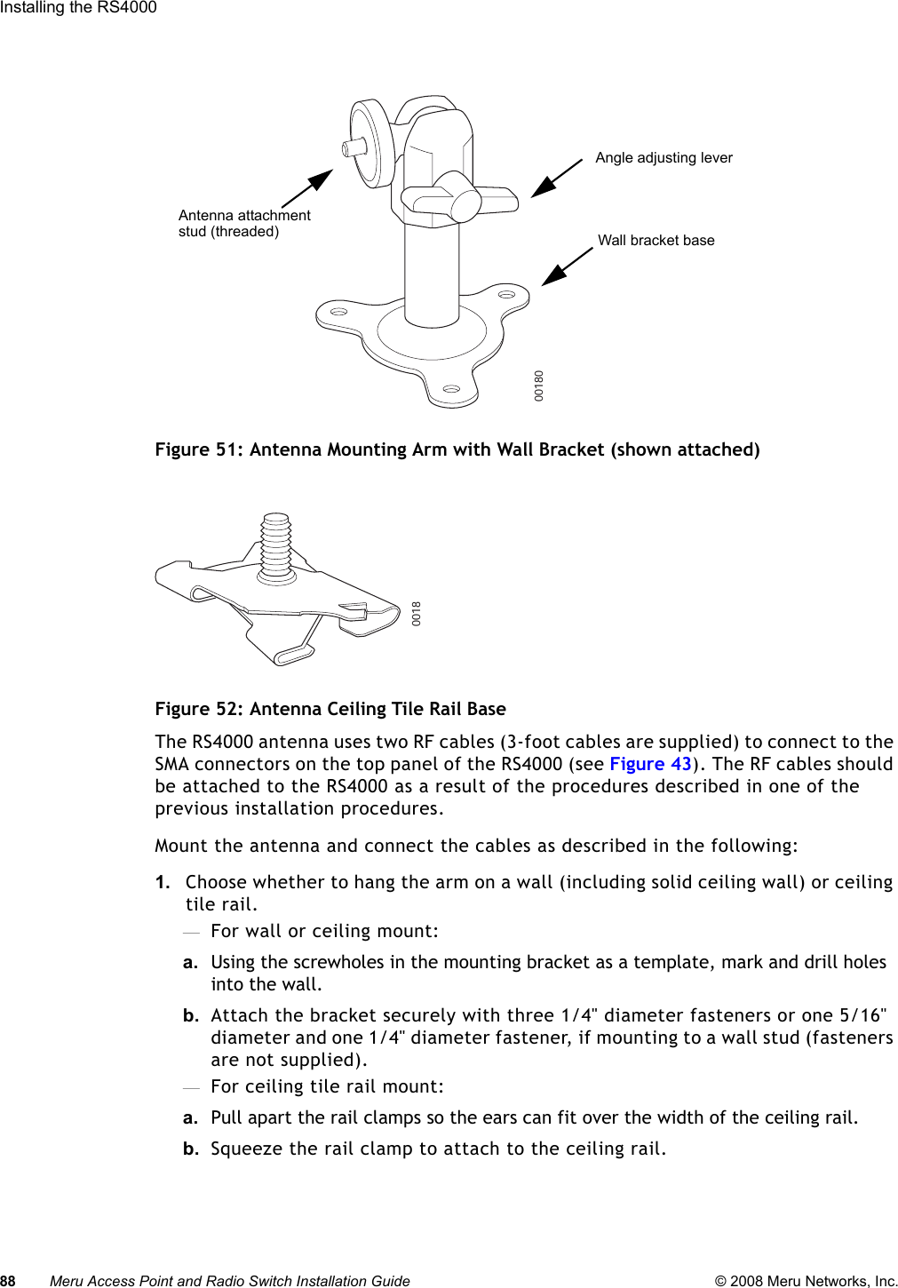
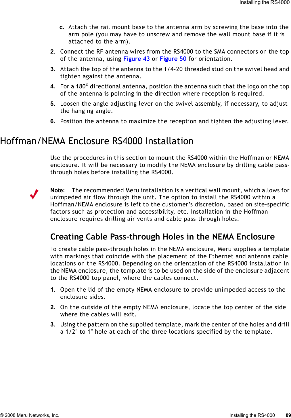
Wiki Guide
HTML
PDF
Info
Views
User Manual
Discussion / Help
Navigation