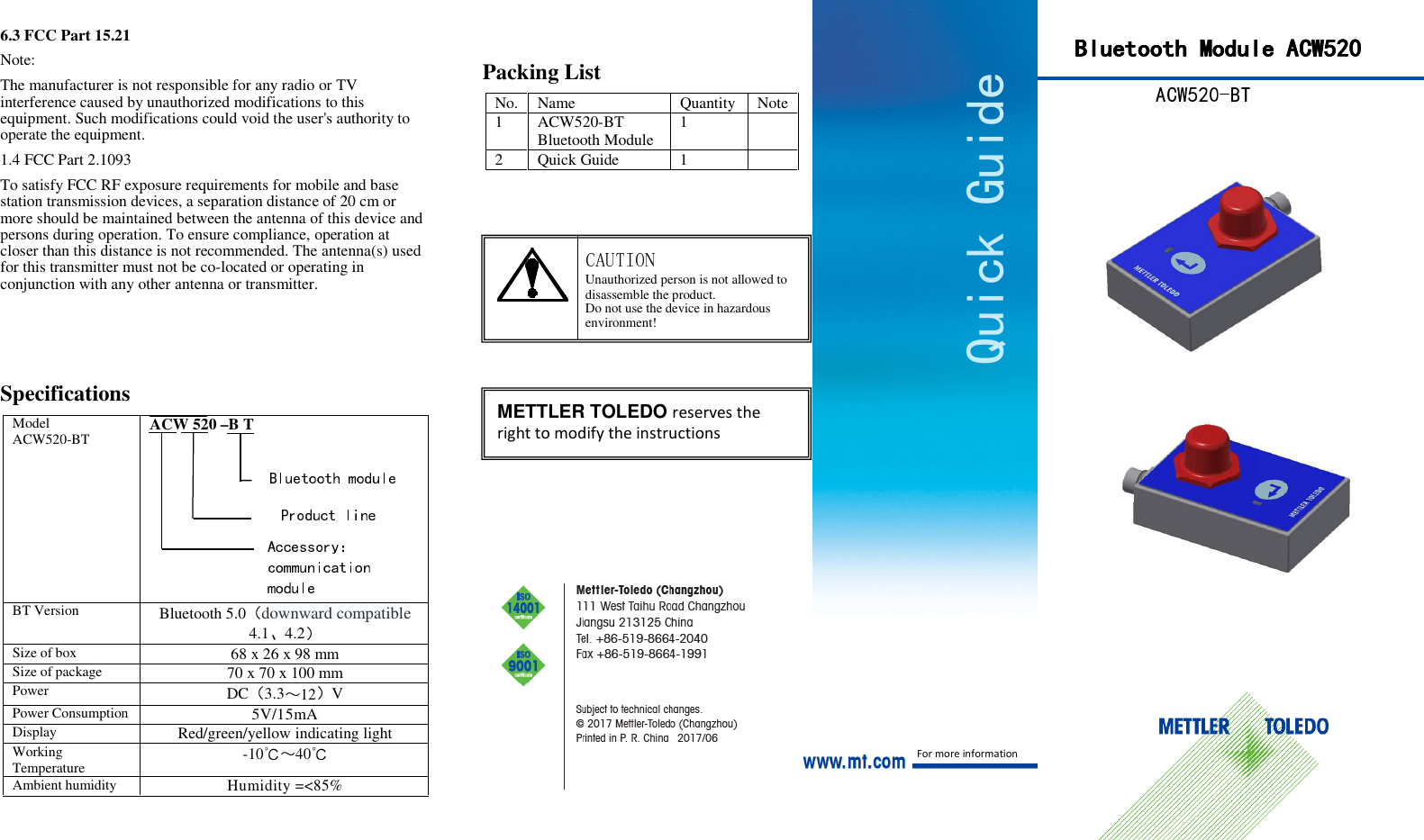
Mettler Toledo 2018MT102 Bluetooth Module ACW520 User Manual

Mettler Toledo (Changzhou) Measurement Technology Ltd. Bluetooth Module ACW520 Users Manual

User Manual

Quick Guide 6.3 FCC Part 15.21 Note: The manufacturer is not responsible for any radio or TV interference caused by unauthorized modifications to this equipment. Such modifications could void the user's authority to operate the equipment. 1.4 FCC Part 2.1093 To satisfy FCC RF exposure requirements for mobile and base station transmission devices, a separation distance of 20 cm or more should be maintained between the antenna of this device and persons during operation. To ensure compliance, operation at closer than this distance is not recommended. The antenna(s) used for this transmitter must not be co-located or operating in conjunction with any other antenna or transmitter. Specifications  Model ACW520-BT ACW 520 –B T BT Version Bluetooth 5.0 downward compatible 4.1 4.2  Size of box 68 x 26 x 98 mm Size of package 70 x 70 x 100 mm Power DC 3.312V Power Consumption 5V/15mA Display Red/green/yellow indicating light Working Temperature -10 40 Ambient humidity Humidity =<85%   Packing List  No. Name  Quantity Note 1 ACW520-BT Bluetooth Module  1  2  Quick Guide  1                                                                                 METTLER TOLEDO reserves the right to modify the instructions Unauthorized person is not allowed to disassemble the product. Do not use the device in hazardous environment! For more information BlueBlueBlueBluetooth Moduletooth Moduletooth Moduletooth Module    ACW520ACW520ACW520ACW520
1. Assemble Plug the joint of ACW520-BT directly into the joint of the device that need to be connected, and then the adapter will start automatically The red light of ACW520-BT will flash once when starting. * How to ensure the ACW520-BT has started After the connection, short press the multi-function button. If the indicating light flashes, that means the Bluetooth has started.  PairingOperating as below after confirmed the starting of  ACW520-BT: 1 Long press the ACW520-BT in the scale until the yellow indicating light flash once.  2 Long press the ACW520-BT which is connected to terminal, until the yellow indicating light flash twice.  3 once the two adapters connect successfully, the green lights of  both flash once. How to determine master and slaven the operation shown above, the ACW520-BT connected to scale is slave and the ACW520-BT connected to terminal is master. Slave: can be connected by other master devices and will record the address of the master in default when first connected. After that, it will not receive the query from other master.  Master: will connect to one of the other paired slaves automatically.  Configuration of master and slave: Configuration type slave  master 1 In the scale With the terminal  search for the corresponding paired ACW520-BT through ACW520-BT After power on the adapter, single click the multi-function button, the indication light of paired adapter will flash at the same time.  Yellow light flashing means salve and green light flashing means master.3. Working mode Bluetooth adapter ACW520-BT can work in the mode of transparent transmission:  Working mode  Description Transparent transmission Data transmitted in both directions between the serial port and the ACW520-BT interface directly * Working mode and slave and master inquiring Single click the multi-function button, the times of  flashing indicates the working mode and the color indicates slave or master.  Indication light flashing  Working mode  Salve or master  yellow twice transparent transmission  slave  green twice transparent transmission  master 4. Transmission mode The function is to turn on or off the multiple to one transmission function. In the multiple to one transmission mode, the devices should be set to multi masters and one slave. Choose one as the slave and connect it with other masters in turn.Transmission mode inquiringTriple slick the multi-function button, and the flashing times correspond to different modes.flashing  transmission mode   red  color once one to one   red  color twice Multiple to one (caution: this function is not available to wireless floor scale)  After power on the ACW520-BT, the transmission mode can be switched.  To switch the transmission mode, long press the multi-function button until the yellow light flashes three times. Then triple click the button to switch in 5 seconds.  After the transmission mode is switched successfully, the adapter will restart automatically and the red light will flash once Caution: the slave and master should be set to the same transmission mode. 5. Restore factory settings Shortcut: when the ACW520-BT is powered on, double click the multi-function button. Then the ACW520-BT will be reset to factory settings and the red light flashes once to tell you the reset has been done. Standard mode: when the ACW520-BT is powered on, long press the paired ACW520-BT until the yellow light flashes three times. Then, short press the multi-function button four times instantly and immediately. The ACW520-BT will also be reset and the red light flashes once. The parameters shown below will be reset to default: Parameter  Keep  Reset to default  Default pairing info.  √ None Master and slave info.  √ Slave Working mode    √  Transparent transmission Transmission mode  √ One to One Baud rate  √ 115200 Name √  Factory preset 6. FCC STATEMENT: This device complies with part 15 of the FCC rules. Part 15C 6.1 FCC Part 15.105 (b) This equipment has been tested and found to comply with the limits for a Class B digital device, pursuant to Part 15 of the FCC Rules. These limits are designed to provide reasonable protection against harmful interference in a residential installation. This equipment generates, uses, and can radiate radio frequency energy, and if not installed and used in accordance with the instructions, may cause harmful interference to radio communications. However, there is no guarantee that interference will not occur in a particular installation. If this equipment does cause harmful interference to radio or television reception, which can be determined by turning the equipment OFF and ON, the user is encouraged to try to correct the interference by one or more of the following measures: - Reorient or relocate the receiving antenna - Increase the separation between the equipment and receiver - Connect the equipment into an outlet on a circuit different from that to which the receiver is connected - Consult the dealer or an experienced radio/TV technician for help . 6.2 FCC Part 15.19(a)(3) Conditions for Use: This device complies with Part15 of the FCC Rules. Operation is subject to the following two conditions: (1) This device may not cause harmful interference, and (2) This device must accept any interference received, including interference that may cause undesired operation.

Navigation menu