Microchip Technology A090667 Zigbit Amp 2.4GHz, Unbalanced Output User Manual AVR appnote nr title
Atmel Norway AS Zigbit Amp 2.4GHz, Unbalanced Output AVR appnote nr title
Contents
- 1. Manual
- 2. Manual-Cert Guide
Manual-Cert Guide
FCC Certification Scenarios for Atmel ZigBits on
Customers' products
Features
• Covers FCC certification scenarios for Atmel ZigBits’ usage
• Analyzes the custom products possibilities and likely-hoods for successful
certification
1 Introduction
Atmel’s Wireless applications play vital role in providing IEEE 802.15.4 –
compliant, ZigBee, and 6LoWPAN wireless solutions using family of RF devices
such as ZigBits, AT86RFxxx,and MegaRF single chip solutions.
These devices are purely based on Atmel’s wide range of high performance,
low-power IEEE 802.15.4-compliant transceivers for the regional 700/800/900MHz
frequency bands available in Europe and North America, and the 2.4GHz band
available world wide.
8-bit
Microcontrollers
Application Note
Rev. [0.5]-AVR-[09/10]
2
AVR[appn
ote nr]
[doc nr]-AVR-[mm]/[yy]
2 Overview
This application note describes an overview of the Certification Scenarios possible
when a designer uses the Atmel ZigBits portfolio. It also covers the changes that
affect Atmel’s existing certification due to minor or major changes on designer’s
hardware.
3 Atmel’s Range of ZigBit Modules and usage scenarios in customer products
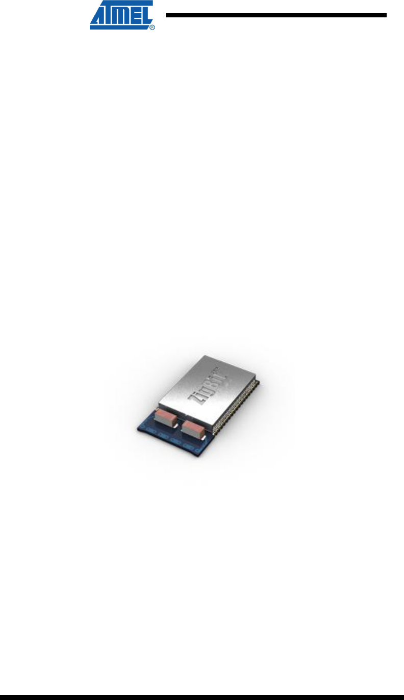
3.1 ATZB-24-A2
It is a ZigBit Module with Dual Chip Antenna, a low-power, 802.15.4 ZigBee module
combination with the popular ATmega1281V MCU and the Atmel AT86RF230 radio
transceiver.
The ATZB-24-A2 comes with a Dual Chip Antenna and eliminates the need for costly
and time-consuming RF development and shortens time to market, while embedded
802.15.4/ZigBee software ensures standards-based wireless connectivity for a wide
range of applications.
Figure 3-1. ATZB-24-A2
3.1.1 Certification scenarios
The following scenario explains the usage of the ATZB-24-A2 module with the
customer’s base board.
3.1.2 Scenario # 1
The ATZB-24-A2 module is bought by a designer and used on the base board.
When designers use the ATZB-24-A2 module on their base board and if the product
does not have any other radiating circuits, the designer need not re-certify the
complete product. In this case the designer has to mention on a visible area in their
product that “Product carries FCC module with FCC ID – VW4A090664”.
AVR[appnote
nr]
3
[doc nr]-AVR-[mm]/[yy]
3.1.3 Scenario # 2
When designers use the ATZB-24-A2 module on their base board and if there are
additional circuits on the base board, with the additionally added circuits comprising of
another radio or switching circuits, the radiations caused by the new circuits may or
may not affect the performance of the ATZB-24-A2. If the ATZB-24-A2 does not get
affected by the additional circuits, still there are possibilities that there could be
emissions from these circuits that are out of limits specified by part 15.247. If these
additional circuits are designed to operate within compliance limits, then the
probability of successful certification is high. For more information on the type of
additional circuits, please refer appendix A.
The FCC ID of ATZB-24-A2 is VW4A090664. Customers have to mention “Product
carries Module with FCC ID VW4A090664” on their product containing the ATZB-24-
A2 ZigBits. The ZigBit’s FCC ID cannot be used in replacement of the final product’s
FCC ID, if there is a requirement to have separate FCC ID for the entire product.
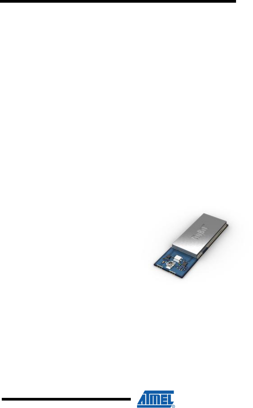
3.2 ATZB-A24-UFL
ZigBit Amp ATZB-A24-UFL is an amplified IEEE 802.15.4/ZigBee module. Its unique
RF design achieves a rare combination of the industry-leading range performance
and low power consumption. The ATZB-A24-UFL module’s small footprint of less
than a square inch of space makes the integration easy, with the built-in U.FL
antenna connector.
Figure 3-2. ATZB-A24-UFL
3.2.1 Certification scenarios
The following scenarios explain the usage of the ATZB-A24-UFL module on
customer’s base board.
3.2.2 Scenario # 1
The ATZB-A24-UFL module is bought by a designer and used on the base board.
When a designer uses ATZB-A24-UFL module on a base board with an antenna
whose gain is less than or equal to 0dBi, and if the product does not have any other
radiating circuit, the designer need not get the product re-certified. In this case the
designer has to mention on a visible area of the product that “Product carries module
FCC ID VW4A090665”

4
AVR[appn
ote nr]
[doc nr]-AVR-[mm]/[yy]
If there are additional circuits on the base board, with the additionally added circuits
comprising of another radio or switching circuits, the radiations caused by the new
circuits may or may not affect the performance of the ATZB-A24-UFL. If the ATZB-
A24-UFL does not get affected by the additional circuits, still there are possibilities
that there could be emissions from these circuits that are out of limits specified by part
15.247. If these additional circuits are designed to operate within compliance limits,
then the probability of successful certification is high. For more information please
refer appendix A.
3.2.3 Scenario # 2
Designers may want to use the ATZB-A24-UFL on the base board and / or use UFL
antenna adaptor and take out the RF signal to a different antenna connector.
Sometimes customers may have requirement to use higher gain antenna than an
antenna with 0dBi gain as mentioned in sec 3.2.2. In such case designer is expected
to re-certify the product with FCC and ETSI. In addition to having a different antenna
and/or connector, there may be radiating circuits on the base board which will call for
re-certification. Refer appendix A. for detailed information about additional circuits on
base board.
The FCC ID of ATZB-A24-UFL is VW4A090668. Customers have to mention “Product
carries Module with FCC ID VW4A090668” on their product containing the ATZB-
A24-UFL ZigBits. The ZigBit’s FCC ID cannot be used in replacement of the final
product’s FCC ID, if there is a requirement to have separate FCC ID for the entire
product.
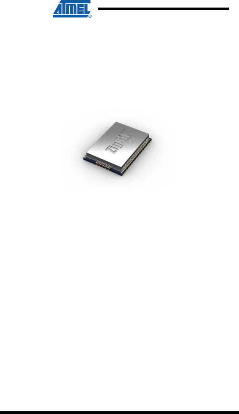
3.3 ATZB-24-B0
ATZB-24-B0 ZigBit Module with Balanced RF Output is a low-power, 802.15.4/
ZigBee module, combination of the ATmega1281V MCU and the AT86RF230 radio
transceiver. ATZB-24-B0 module is very similar to the ATZB-24-A2 module and unlike
ATZB-24-A2 module it offers the flexibility of adding design oriented external antenna
in the application board.
ATZB-24-B0 minimizes bill of materials (BOM) and shortens time to market, while
embedded 802.15.4/ ZigBee software ensures standards-based wireless connectivity
for a wide range of applications.
AVR[appnote
nr]
5
[doc nr]-AVR-[mm]/[yy]
Figure 3-3. ATZB-24-B0
3.3.1 Certification scenarios
The following scenarios explain the usage of the ATZB-24-B0 module on customer’s
base board.
3.3.2 Scenario # 1
The ATZB-24-B0 module is bought by designers and used on a base board.
Atmel’s ATZB-24-B0 Module has been certified under Limited Modular category of
FCC part 15 subpart C. Limited modular certification applies to modules that do not
fully meet the requirements for a single modular certification. The ATZB-24-B0
module meets all but the requirement of having an on-board antenna or connector.
Designers are required to re-certify their products carrying this module as this module
brings out the Balanced RF Output without ending up in any antenna structure on the
module. Since there is RF signal flowing on the designer’s base board in such case,
the entire product has to be re-tested and certified. The new FCC ID obtained by the
designer has to be used to meet regulatory requirements.
By following the recommended design to connect the RF signal from B0 Module pins
to the Antenna, the probability of success in Re-certification tests is very high. This is
because the module has been successfully certified with Atmel’s Base board
reference. The Base board reference design that applies for the ATZB-24-B0 is
ATZB-EVB-24-SMA.
3.3.3 Scenario # 2
In cases were usage explained in Scenario #1 applies and additionally, application
dependent circuits as explained in Appendix A is used on the Base board, this
scenario applies.
If the circuits on the customer’s base board are either Intentional or Unintentional
Radiators or both, then the customer has to certify the entire product carrying the
ATZB-24-B0 Module. The probability of a successful certification lies with how good
or bad, the additional circuits on base board are designed in terms of regulatory
compliance. Atmel’s Base board reference design- ATZB-EVB-24-SMA in this case
can help customers in assuring success in the module related tests alone.
6
AVR[appn
ote nr]
[doc nr]-AVR-[mm]/[yy]
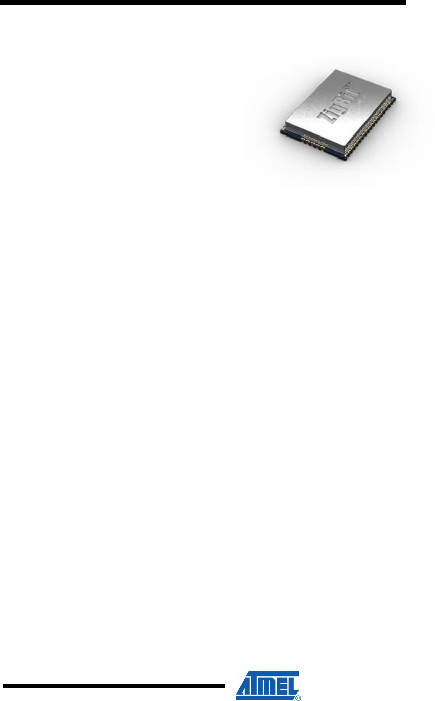
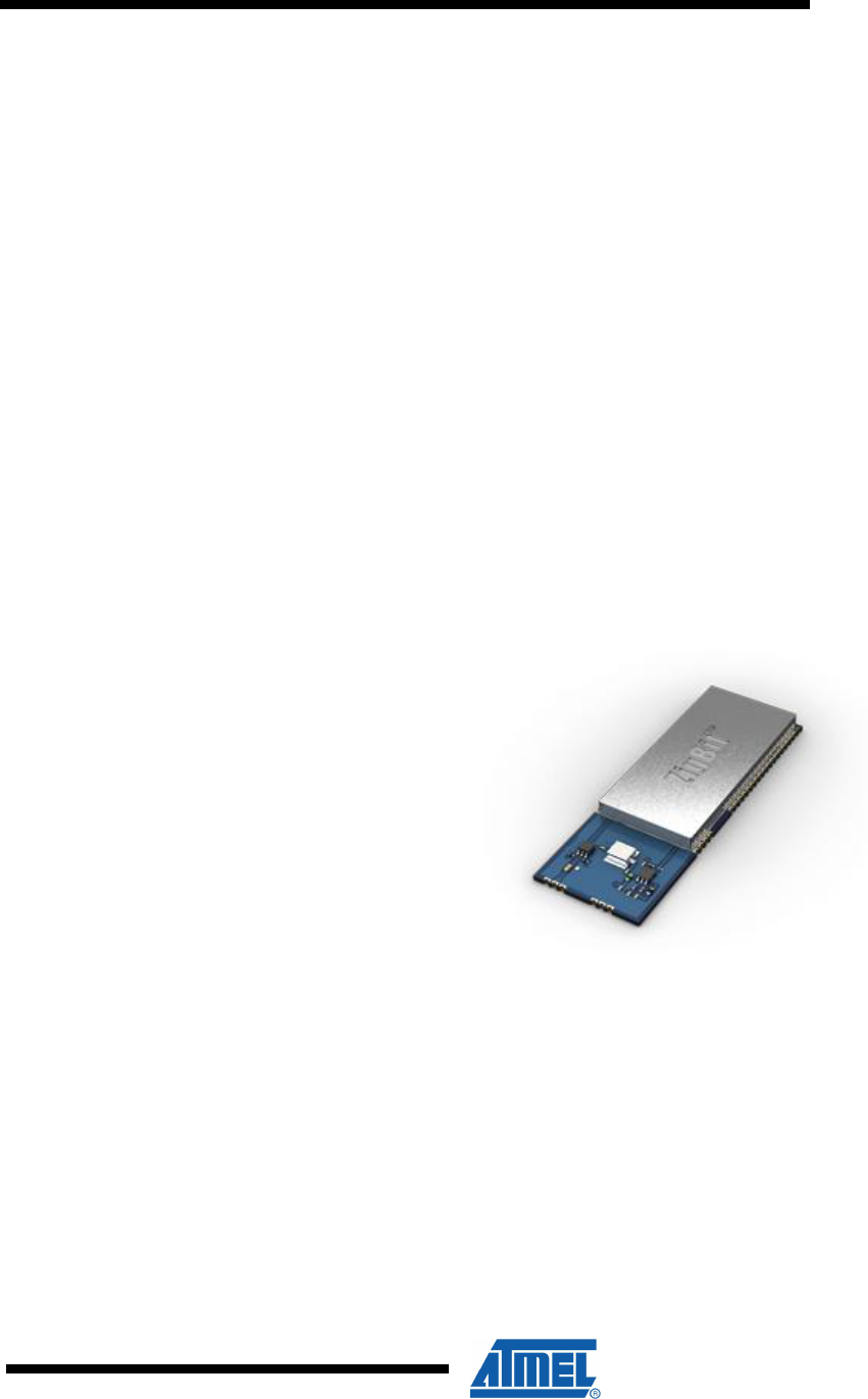
3.4 ATZB-900-B0
ATZB-900-B0 is an ultra-compact, low-power, high-sensitivity 868MHz / 915MHz
802.15.4/ZigBee OEM module from Atmel.
ATZB-900-B0 modules eliminate the need for costly and time-consuming RF
development, minimizes bill of materials (BOM), and shortens time to market for a
wide range of wireless applications, while embedded 802.15.4 / ZigBee software
ensures standards-based wireless connectivity.
Figure 3-4. ATZB-900-B0
3.4.1 Certification scenarios
The following scenarios explain the usage of the ATZB-900-B0 module on customer’s
base board.
3.4.2 Scenario # 1
The ATZB-900-B0 module is bought by designers and used on their base board.
Atmel’s ATZB-900-B0 Module has been certified under Limited Modular category of
FCC part 15 subpart C.
Limited modular certification applies to modules that do not fully meet the
requirements for a single modular certification. The ATZB-900-B0 module meets all
but the requirement of having an on-board antenna or connector.
Designers are required to re-certify their products carrying this module as this module
brings out the Balanced RF Output without ending up in any antenna structure on the
module. Since there is RF signal flowing on the designer’s base board in such case,
the entire product has to be re-tested and certified. The new FCC ID obtained by the
designer has to be used to meet regulatory requirements.
By following the recommended design to connect the RF signal from B0 Module pins
to the Antenna, the probability of success in Re-certification tests is very high. This is
because the module has been successfully certified with Atmel’s Base board
reference. The Base board reference design that applies for the ATZB-900-B0 is
ATZB-EVB-900-SMA.
AVR[appnote
nr]
7
[doc nr]-AVR-[mm]/[yy]
3.4.3 Scenario # 2
In cases were usage explained in Scenario #1 applies and additionally, application
dependent circuits as explained in Appendix A is used on the Base board, this
scenario applies.
If the circuits on the customer’s base board are either Intentional or Unintentional
Radiators or both, then the customer has to certify the entire product carrying the
ATZB-900-B0 Module. The probability of a successful certification lies with how good
or bad, the additional circuits on base board are designed in terms of regulatory
compliance. Atmel’s Base board reference design- ATZB-EVB-900-SMA in this case
can help customers in assuring success in the module related tests alone.
3.5 ATZB-A24-U0
ZigBit Amp ATZB-A24-U0 is an amplified IEEE 802.15.4/ZigBee module with low
power consumption and small footprint of less than a square inch of space.
ATZB-A24-U0 Module with Un-balanced RF Output minimizes bill of materials (BOM)
and shortens time to market, while embedded 802.15.4/ ZigBee software ensures
standards-based wireless connectivity for a wide range of applications.
Figure 3-5. ATZB-A24-U0
3.5.1 Certification scenarios
The following scenarios will explain the changes that can be done on the ATZB-A24-
U0 module and / or on their carrier boards on customer’s base board.
3.5.2 Scenario # 1
The ATZB-A24-U0 module is bought by designers and used on customer’s base
board.
Atmel’s ATZB-A24-U0 Module has been certified under Limited Modular category of
FCC part 15 subpart C.
Limited modular certification applies to modules that do not fully meet the
requirements for a single modular certification. The ATZB-A24-U0 module meets all
but the requirement of having an on-board antenna or connector.

8
AVR[appn
ote nr]
[doc nr]-AVR-[mm]/[yy]
Designers are required to re-certify their products carrying this module as this module
brings out the UnBalanced RF Output without ending up in any antenna structure on
the module. Since there is RF signal flowing on the designer’s base board in such
case, the entire product has to be re-tested and certified. The new FCC ID obtained
by the designer has to be used to meet regulatory requirements.
By following the recommended design to connect the RF signal from U0 Module pin
to the Antenna, the probability of success in Re-certification tests is very high. This is
because the module has been successfully certified with Atmel’s Base board
reference. The Base board reference design that applies for the ATZB-A24-U0 is
ATZB-EVB-A24-SMA. The recommended antenna gain for ATZB-A24-U0 on a
baseboard is less than or equal to 0dBi.
3.5.3 Scenario # 2
In cases were usage explained in Scenario #1 applies and additionally, application
dependent circuits as explained in Appendix A is used on the Base board OR
antenna with gain of more than 0dBi (directional antenna) is used, this scenario
applies.
If the circuits on the customer’s base board are either Intentional or Unintentional
Radiators or both, then the customer has to certify the entire product carrying the
ATZB-A24-U0 Module. The probability of a successful certification lies with how good
or bad, the additional circuits on base board are designed in terms of regulatory
compliance. Atmel’s Base board reference design- ATZB-EVB-A24-SMA in this case
can help customers in assuring success in the module related tests alone.
4 Country Specific certifications
4.1 Japan
The ZigBits that are intended to use in Japan must be certified with TELEC
certification system. TELEC is the major organization providing the certification
services as a registered certification body.
FCC approval and CE declaration are not recognized by TELEC.
TELEC certification requires the ZigBits to be tested and certified in an accredited test
lab within Japan according to TELEC standards.
The probability of getting certified is high if the products already hold FCC / CE
certification, since the TELEC specifications on the limits are similar to FCC/CE.
Refer RF TELEC standard for more details.
4.2 Korea
The ZigBits and the ZigBit’s products that are to be used in Korea must be certified
with KCC (Korea Communications Commission) certification body. KCC is the
institution providing the certification services as a registered certification body.
The product which even passes the FCC / CE certification must undergo in-country
testing and certification. But the probability of getting certified is high in case if the
products already hold FCC / CE certification.

AVR[appnote
nr]
9
[doc nr]-AVR-[mm]/[yy]
4.3 Taiwan
In Taiwan, NCC (National Communications Commission) approval is required for the
end product using ZigBits. In-country testing is required since FCC / CE certifications
are not accepted. ETSI / FCC will be the reference standard for certification
regulations. The probability of getting certified is high in case if the products already
hold FCC / CE certification.
4.4 China
The ZigBits and the ZigBit’s products that are to be used in China must under go in-
country certification as mentioned by SRRC (State Radio Regulatory Committee).
SRRC is a radio management of P.R China.
The product which even passes the FCC / CE certification must undergo in-country
testing and certification. But the probability of getting certified is high in case if the
products already hold FCC / CE certification.
4.5 Australia
RF Products that are used inside Australia must have the C-Tick mark. CE
declaration is recognized in Australia. The ACMA (Australian Communication and
Media Authority) accepts products that are tested for ETSI limits. The product has to
be registered with ACMA for obtaining and using the C-Tick mark.
5 SAR Requirements
SAR, Specific absorption rate, is a measure of radiated RF energy absorbed by a
human body tissue. SAR is expressed in watts per kilogram (W/kg) of biological
tissue. The ZigBit modules must undergo SAR tests and qualification before
commercial release if the device is operating with 20cm distance to the human body.
SAR is measured using special lab equipments and environments. The device under
test is placed in a phantom shell with tissue and checked for RF field exposure. The
phantom is in human body shape and the DUT is positioned in the head part and
body part. Probe positioner and device positioner are used to move the respective
devices and simulated data is acquired and analyzed.
SAR testing requirements on customer’s base board has to be decided, based on the
nature of intended application.
6 Appendix
6.1 Appendix A
Designers can use the ZigBit alone or with additional circuits on the base board. In
this case following points need to be taken care.
The custom product may contain any of the following circuits
1. High Voltage
2. Switching circuits

10
AVR[appn
ote nr]
[doc nr]-AVR-[mm]/[yy]
3. Secondary or another radio part
When the above mentioned blocks are bought out items and are already pre-certified
individually, the designer is expected to verify the entire product with FCC accredited
Lab. The ZigBit’s FCC ID is still valid but cannot be used as a final product’s FCC ID
because there are additional circuits in the product. But since ZigBits already carry
FCC ID and are certified, the likelihood of getting the entire product certified is high,
since the rest of circuits in the product are pre-certified too.
If circuits listed above are not present in Customer’s base board and if customer’s
base board is only for carrying the ZigBit ATZB-24-A2 or ATZB-A24-UFL module,
then there is no need for re-certification
When all or any of the above mentioned blocks are not pre-certified / non-compliant,
irrespective of the scenarios mentioned for all of the ZigBits, the designers must
certify the entire product and the likelihood of successful certification depends on the
circuit design of the extra circuits added apart from the ZigBit.
Testing and maintaining reports will be useful in a case when FCC / ETSI conducts
audit on the product and asks the product owner for test reports and affiliated
documents in a short notice
AVR[appnote
nr]
11
[doc nr]-AVR-[mm]/[yy]
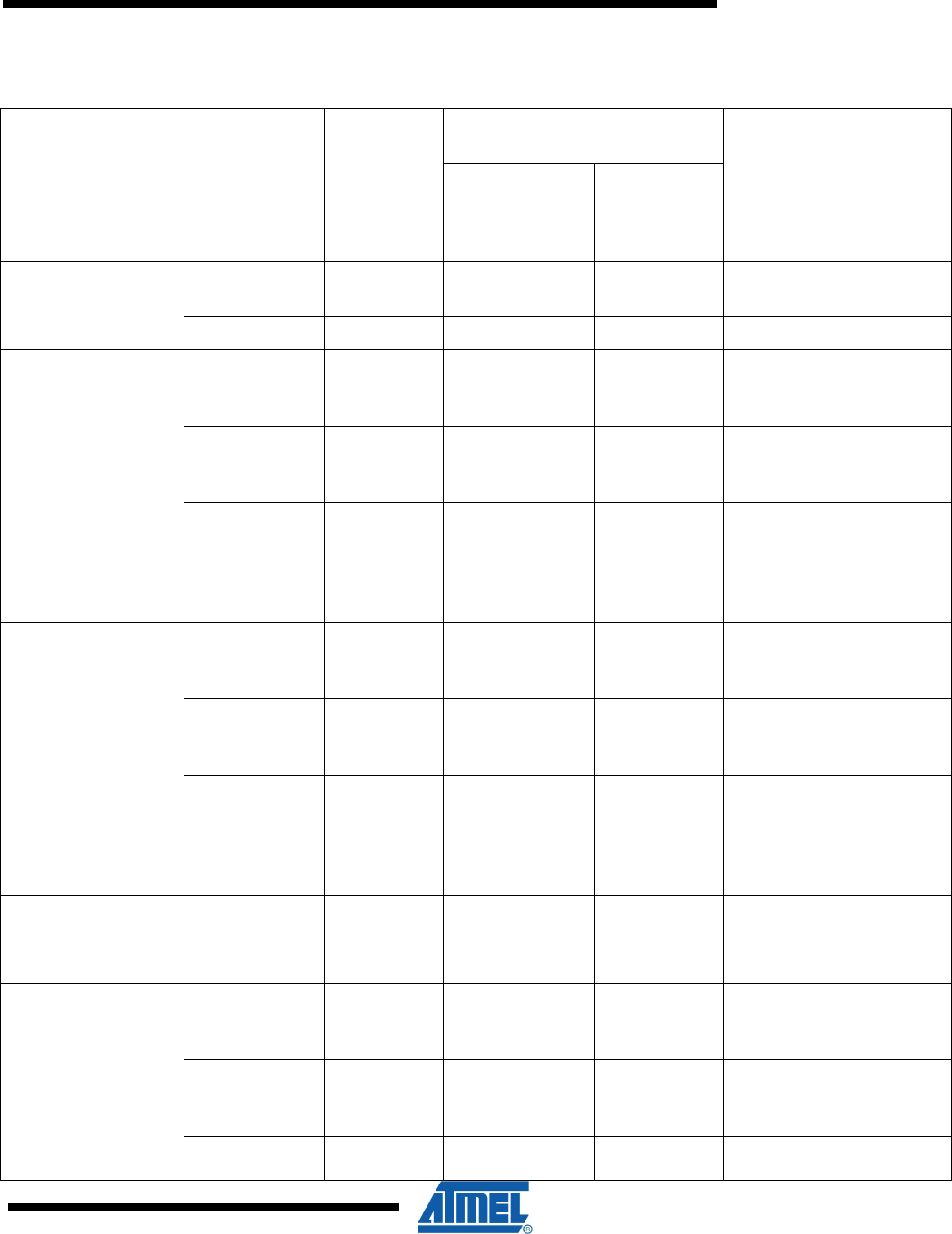
6.2 Appendix B
Constraints /
ZigBits
Scenario 1
Scenario 2
Additional Circuits in Base
board
FCC approval
Requirement
Non compliant
circuits /
Uncertified
circuits
Compliant
circuits /
Pre-certified
circuits
ATZB-24-A2
√
√
Mention FCC ID on Label
of product
√
√
Recertification
ATZB-24-B0
√
Recertification;
Probability of successful
certification is high
√
√
Recertification;
Probability of successful
certification is high
√
√
Recertification;
Probability of successful
certification depends on
Additional circuits on
baseboard.
ATZB-900-B0
√
Recertification;
Probability of successful
certification is high
√
√
Recertification;
Probability of successful
certification is high
√
√
Recertification;
Probability of successful
certification depends on
Additional circuits on
baseboard.
ATZB-A24-UFL
√
√
Mention FCC ID on Label
of product
√
√
Recertification
ATZB-A24-U0
√
Recertification;
Probability of successful
certification is high
√
√
Recertification;
Probability of successful
certification is high
√
√
Recertification;
Probability of successful

12
AVR[appn
ote nr]
[doc nr]-AVR-[mm]/[yy]
certification depends on
Additional circuits on
baseboard.

[doc nr]-AVR-[mm]/[yy]
Disclaimer
Headquarters
International
Atmel Corporation
2325 Orchard Parkway
San Jose, CA 95131
U.S.A.
Tel: (+1) (408) 441-0311
Fax: (+1) (408) 487-2600
Atmel Asia Limited
Unit 01-5 & 16, 19F
BEA Tower, Millennium City 5
418 Kwun Tong Road
Kwun, Tong, Kowloon
HONG KONG
Tel: (852) 2245-6100
Fax: (852) 27232-1369
Product Contact
Atmel Munich GmbH
Business Campus
Parkring 4
D- 85748 Garching b.
MUNICH
Tel.: (+49) 89-31970-111
Fax: (+49) 89-3194621
Atmel Japan
9F, Tonetsu Shinkawa Bldg.
1-24-8 Shinkawa
Chuo-ku, Tokyo 104-003
JAPAN
Tel: (+81) 3-3523-3551
Fax: (+81) 3-3523-7581
Web Site
http://www.atmel.com/
Technical Support
avr@atmel.com
Sales Contact
www.atmel.com/contacts
Literature Request
www.atmel.com/literature
Disclaimer: The information in this document is provided in connection with Atmel products. No license, express or implied, by estoppel or otherwise, to any
intellectual property right is granted by this document or in connection with the sale of Atmel products. EXCEPT AS SET FORTH IN ATMEL’S TERMS AND
CONDITIONS OF SALE LOCATED ON ATMEL’S WEB SITE, ATMEL ASSUMES NO LIABILITY WHATSOEVER AND DISCLAIMS ANY EXPRESS, IMPLIED
OR STATUTORY WARRANTY RELATING TO ITS PRODUCTS INCLUDING, BUT NOT LIMITED TO, THE IMPLIED WARRANTY OF MERCHANTABILITY,
FITNESS FOR A PARTICULAR PURPOSE, OR NON-INFRINGEMENT. IN NO EVENT SHALL ATMEL BE LIABLE FOR ANY DIRECT, INDIRECT,
CONSEQUENTIAL, PUNITIVE, SPECIAL OR INCIDENTAL DAMAGES (INCLUDING, WITHOUT LIMITATION, DAMAGES FOR LOSS OF PROFITS,
BUSINESS INTERRUPTION, OR LOSS OF INFORMATION) ARISING OUT OF THE USE OR INABILITY TO USE THIS DOCUMENT, EVEN IF ATMEL HAS
BEEN ADVISED OF THE POSSIBILITY OF SUCH DAMAGES. Atmel makes no representations or warranties with respect to the accuracy or completeness of the
contents of this document and reserves the right to make changes to specifications and product descriptions at any time without notice. Atmel does not make any
commitment to update the information contained herein. Unless specifically provided otherwise, Atmel products are not suitable for, and shall not be used in,
automotive applications. Atmel’s products are not intended, authorized, or warranted for use as components in applications intended to support or sustain life.
© 2010 Atmel Corporation. All rights reserved. Atmel®, logo and combinations thereof, AVR® and others, are the registered trademarks or
trademarks of Atmel Corporation or its subsidiaries. Other terms and product names may be trademarks of others.