Microlise ML10 ML10 Tracking Unit User Manual ML10 Technical Manual
Microlise Limited ML10 Tracking Unit ML10 Technical Manual
UserManual.wiki
>
Microlise
>
ML10 User Manual
>
User Manual
Contents
1.
QOQWT32I Module - User Manual
2.
User Manual
3.
QOQBLE113 Module - User Manual
4.
QIPEHS6 Module - User Manual
User Manual
Navigation menu
Upload a User Manual
Namespaces
Wiki Guide
HTML
PDF
Info
Views
User Manual
Discussion / Help
Navigation
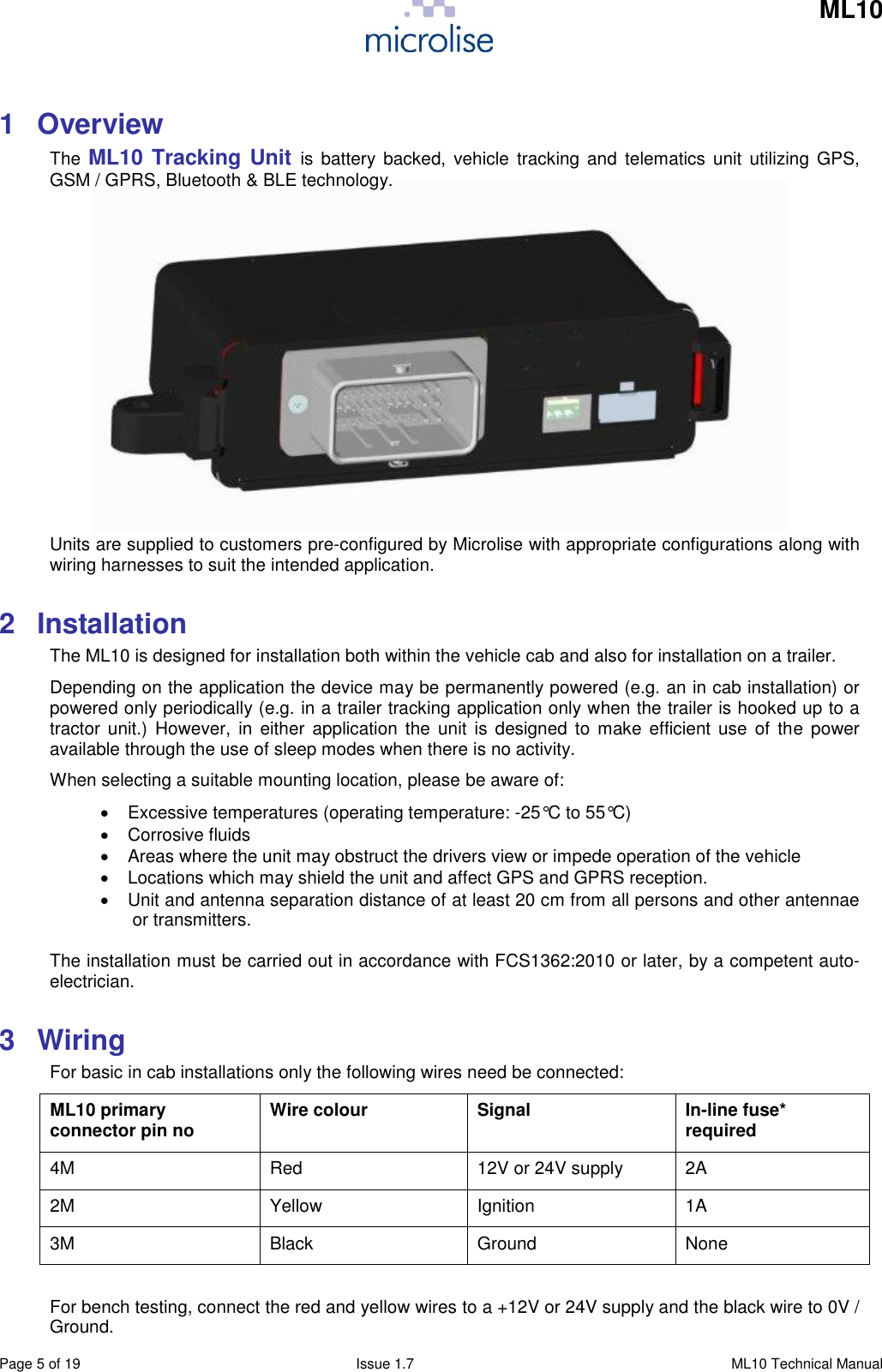
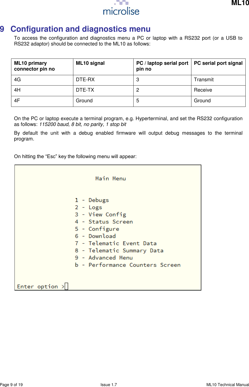
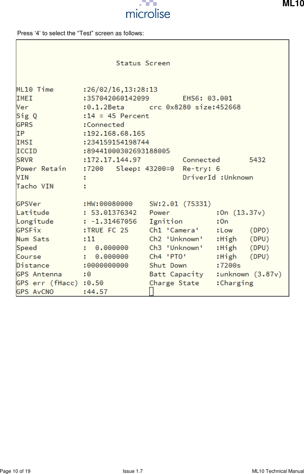
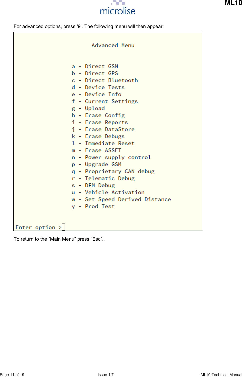
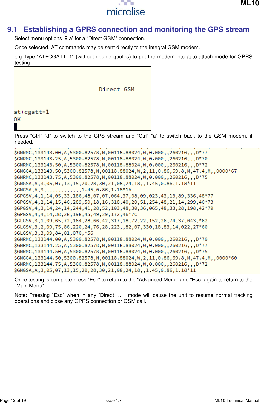
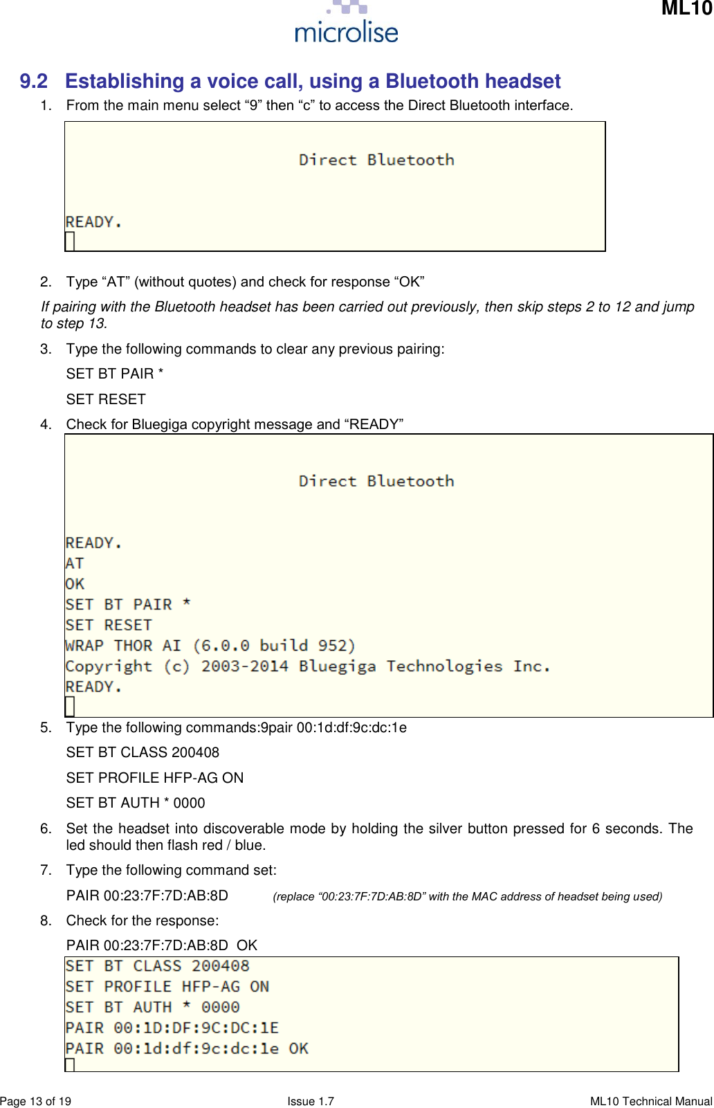
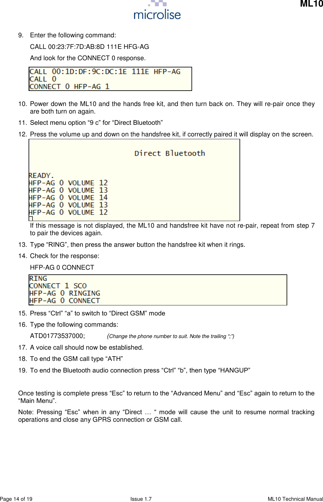
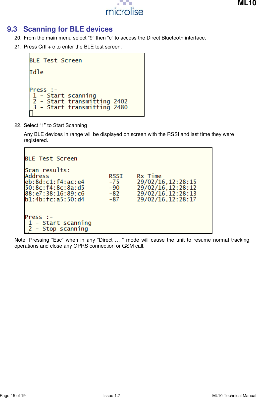
![ML10 Page 16 of 19 Issue 1.7 ML10 Technical Manual 9.4 Setting Bluetooth in permanent transmit mode 1. From the main menu select “9” then “c” to access the Direct Bluetooth interface. 2. Type “AT” (without quotes) and check for response “OK” 3. Type “TEST TXSTART [channel frequency] 0xFF3F [modulation frequency]” Where channel frequency is expressed in MHz (2402 – 2480) And modulation frequency is in a range from 0 – 327676, expressed in values between 0 – 256 Eg. “TEST TXSTART 2402 0xFF3F 0” 4. To stop transmiting type “PAUSE” into the Direct Bluetooth screen. Note: Pressing “Esc” when in any “Direct … “ mode will cause the unit to resume normal tracking operations and close any GPRS connection or GSM call. 9.5 Setting BLE in permanent transmit mode 1. From the main menu select “9” then “c” to access the Direct Bluetooth interface. 2. Press Crtl + c to enter the BLE test screen. 3. Select option 2 to transmit at 2402 MHz, and option 3 to transmit at 2480MHz Note: Pressing “Esc” when in any “Direct … “ mode will cause the unit to resume normal tracking operations and close any GPRS connection or GSM call.](https://usermanual.wiki/Microlise/ML10.User-Manual/User-Guide-3202930-Page-16.png)