Microsoft NSD-3AW Dual Band Tri Mode CDMA Cellular Phone User Manual EE1 EPS
Microsoft Mobile Oy Dual Band Tri Mode CDMA Cellular Phone EE1 EPS
Contents
- 1. Manual
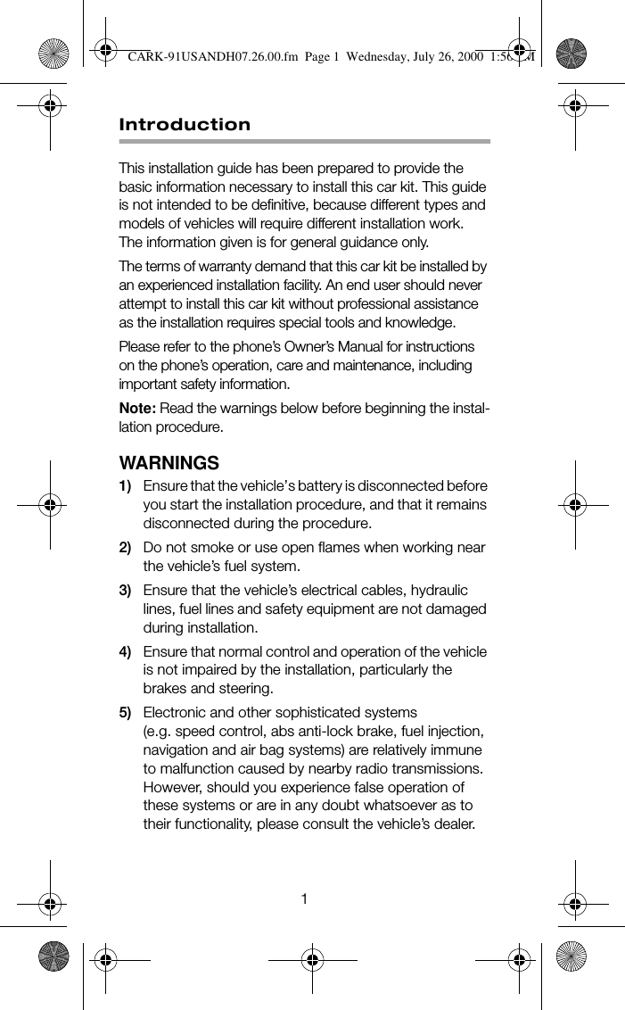
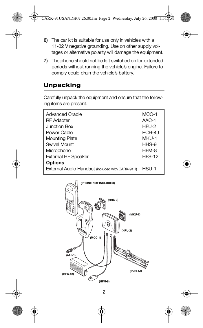
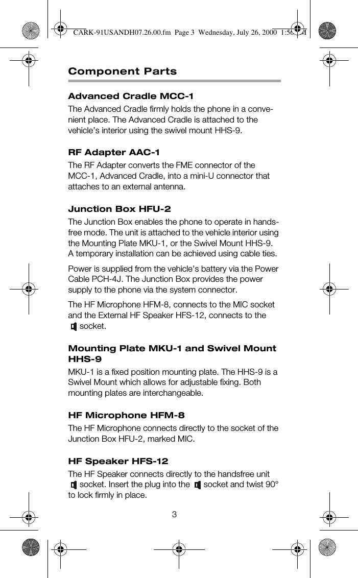
- 2. Car Kit Installation Guide
- 3. Modified Car Kit Instructions
- 4. Body Warn Statement
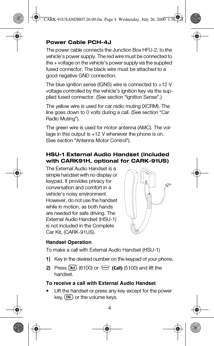
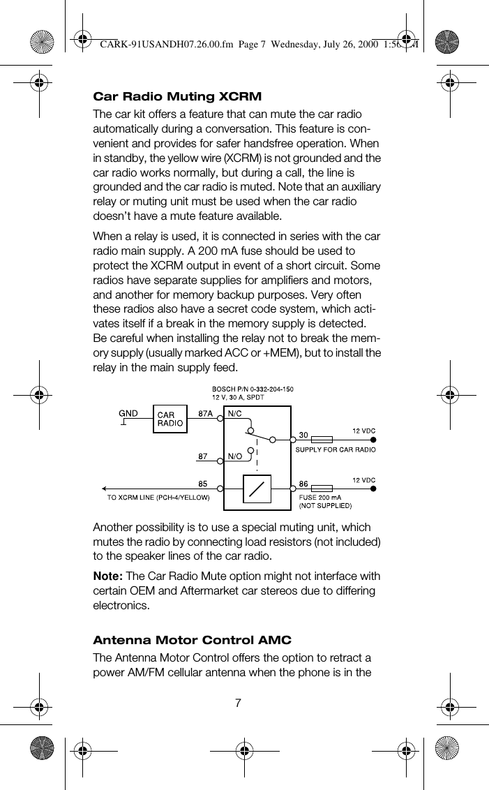
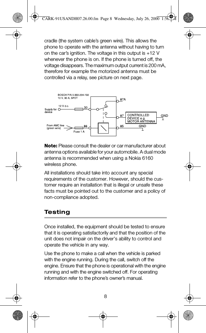
Modified Car Kit Instructions