Microsoft NSD-3AW Dual Band Tri Mode CDMA Cellular Phone User Manual EE1 EPS
Microsoft Mobile Oy Dual Band Tri Mode CDMA Cellular Phone EE1 EPS
Contents
- 1. Manual
- 2. Car Kit Installation Guide
- 3. Modified Car Kit Instructions
- 4. Body Warn Statement
Modified Car Kit Instructions
0
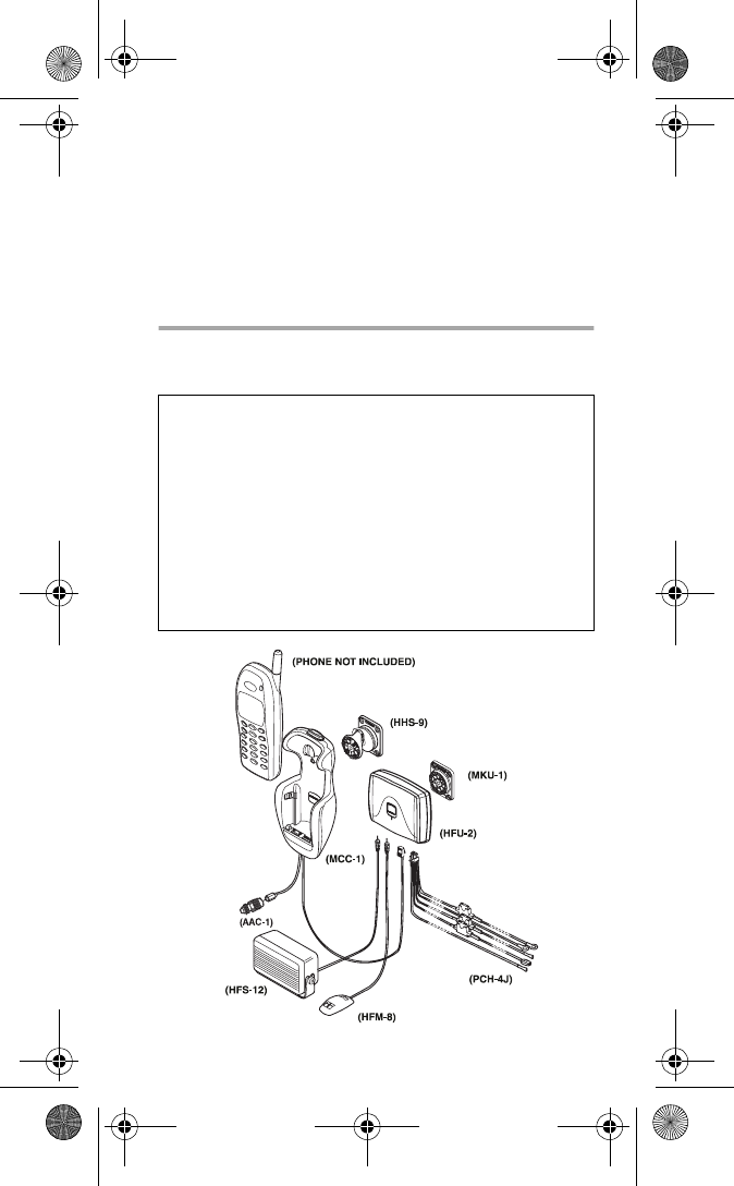
Complete Car Kit
(CARK-91US/CARK-91H)
For use with Nokia 5100 and 6100 Series
Wireless Phones
CARK-91USANDH07.26.00.fm Page 0 Wednesday, July 26, 2000 1:56 PM
1
Introduction
This installation guide has been prepared to provide the
basic information necessary to install this car kit. This guide
is not intended to be definitive, because different types and
models of vehicles will require different installation work.
The information given is for general guidance only.
The terms of warranty demand that this car kit be installed by
an experienced installation facility. An end user should never
attempt to install this car kit without professional assistance
as the installation requires special tools and knowledge.
Please refer to the phone’s Owner’s Manual for instructions
on the phone’s operation, care and maintenance, including
important safety information.
Note: Read the warnings below before beginning the instal-
lation procedure.
WARNINGS
1) Ensure that the vehicle’s battery is disconnected before
you start the installation procedure, and that it remains
disconnected during the procedure.
2) Do not smoke or use open flames when working near
the vehicle’s fuel system.
3) Ensure that the vehicle’s electrical cables, hydraulic
lines, fuel lines and safety equipment are not damaged
during installation.
4) Ensure that normal control and operation of the vehicle
is not impaired by the installation, particularly the
brakes and steering.
5) Electronic and other sophisticated systems
(e.g. speed control, abs anti-lock brake, fuel injection,
navigation and air bag systems) are relatively immune
to malfunction caused by nearby radio transmissions.
However, should you experience false operation of
these systems or are in any doubt whatsoever as to
their functionality, please consult the vehicle’s dealer.
CARK-91USANDH07.26.00.fm Page 1 Wednesday, July 26, 2000 1:56 PM
2
6) The car kit is suitable for use only in vehicles with a
11-32 V negative grounding. Use on other supply vol-
tages or alternative polarity will damage the equipment.
7) The phone should not be left switched on for extended
periods without running the vehicle’s engine. Failure to
comply could drain the vehicle’s battery.
Unpacking
Carefully unpack the equipment and ensure that the follow-
ing items are present.
Advanced Cradle MCC-1
RF Adapter AAC-1
Junction Box HFU-2
Power Cable PCH-4J
Mounting Plate MKU-1
Swivel Mount HHS-9
Microphone HFM-8
External HF Speaker HFS-12
Options
External Audio Handset (included with CARK-91H) HSU-1
CARK-91USANDH07.26.00.fm Page 2 Wednesday, July 26, 2000 1:56 PM
3
Component Parts
Advanced Cradle MCC-1
The Advanced Cradle firmly holds the phone in a conve-
nient place. The Advanced Cradle is attached to the
vehicle’s interior using the swivel mount HHS-9.
RF Adapter AAC-1
The RF Adapter converts the FME connector of the
MCC-1, Advanced Cradle, into a mini-U connector that
attaches to an external antenna.
Junction Box HFU-2
The Junction Box enables the phone to operate in hands-
free mode. The unit is attached to the vehicle interior using
the Mounting Plate MKU-1, or the Swivel Mount HHS-9.
A temporary installation can be achieved using cable ties.
Power is supplied from the vehicle’s battery via the Power
Cable PCH-4J. The Junction Box provides the power
supply to the phone via the system connector.
The HF Microphone HFM-8, connects to the MIC socket
and the External HF Speaker HFS-12, connects to the
socket.
Mounting Plate MKU-1 and Swivel Mount
HHS-9
MKU-1 is a fixed position mounting plate. The HHS-9 is a
Swivel Mount which allows for adjustable fixing. Both
mounting plates are interchangeable.
HF Microphone HFM-8
The HF Microphone connects directly to the socket of the
Junction Box HFU-2, marked MIC.
HF Speaker HFS-12
The HF Speaker connects directly to the handsfree unit
socket. Insert the plug into the socket and twist 90°
to lock firmly in place.
CARK-91USANDH07.26.00.fm Page 3 Wednesday, July 26, 2000 1:56 PM
4
Power Cable PCH-4J
The power cable connects the Junction Box HFU-2, to the
vehicle’s power supply. The red wire must be connected to
the + voltage on the vehicle’s power supply via the supplied
fused connector. The black wire must be attached to a
good negative GND connection.
The blue ignition sense (IGNS) wire is connected to +12 V
voltage controlled by the vehicle’s ignition key via the sup-
plied fused connector. (See section “Ignition Sense”.)
The yellow wire is used for car radio muting (XCRM). The
line goes down to 0 volts during a call. (See section “Car
Radio Muting”).
The green wire is used for motor antenna (AMC). The vol-
tage in this output is +12 V whenever the phone is on.
(See section “Antenna Motor Control”).
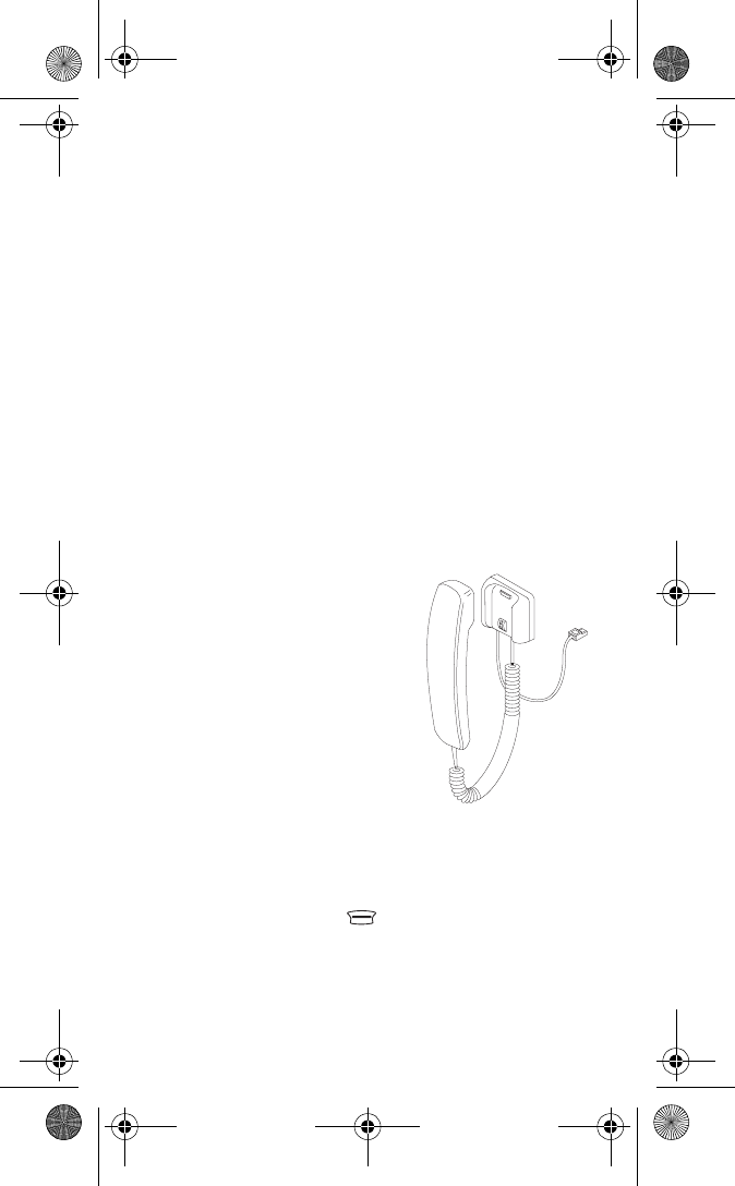
HSU-1 External Audio Handset (included
with CARK91H, optional for CARK-91US)
The External Audio Handset is a
simple handset with no display or
keypad. It provides privacy for
conversation and comfort in a
vehicle’s noisy environment.
However, do not use the handset
while in motion, as both hands
are needed for safe driving. The
External Audio Handset (HSU-1)
is not included in the Complete
Car Kit, (CARK-91US).
Handset Operation
To make a call with External Audio Handset (HSU-1)
1) Key in the desired number on the keypad of your phone.
2) Press ó (6100) or +&DOO, (5100) and lift the
handset.
To receive a call with External Audio Handset
• Lift the handset or press any key except for the power
key, ô or the volume keys.
CARK-91USANDH07.26.00.fm Page 4 Wednesday, July 26, 2000 1:56 PM
5
When you lift the Audio Handset from its holder, the
HF-loudspeaker and HF-microphone will be muted and
you can speak in privacy.
To end a call with External Audio Handset
• Replace the handset or press ô (6100) or #
+(QG, (5100).
To switch from handsfree (HF) operation to handset
operation
•Lift the handset
To switch from handset operation to handsfree (HF)
operation
• Press the left ñ 2SWLRQV soft key (6100) or
+2SWLRQV, (5100) once and replace the handset in
5 seconds. If you do not press the left ñ 2SWLRQV
(6100) or #+2SWLRQV, (5100) the call will
terminate!
External Mobile Antenna (not included)
The wireless phone is designed to operate with a high quality
external antenna. Due to many different types of antennas,
an antenna is NOT included as part of this kit. Please, con-
sult the dealer to find out which is the most suitable
antenna type for your installation. Please note that the
antenna is required for proper operation.
Installation
Special attention must be given to the positioning of the car
kit accessories.
The positioning of the Active Cradle MCC-1 is the most im-
portant factor when trying to achieve the most comfortable
position for the user. The location of the cradle should be
selected so that the visibility of the phone’s display is good
under all lighting conditions, but not so that the driver’s
attention is easily distracted. The cradle should be located
so that the driver can easily reach the keypad. Under no
circumstances should the cradle prevent the driver from
CARK-91USANDH07.26.00.fm Page 5 Wednesday, July 26, 2000 1:56 PM
controlling or operating the vehicle in any way or obstruct
the driver’s view of traffic.
The Junction Box HFU-2 can be installed in a hidden loca-tion
since there is no need to disconnect cables during
normal operation. Ensure that the microphone is as close
to the driver’s mouth as possible, and attached to a surface
that is mechanically quiet. The microphone should be
mounted at least 3 ft/1 m away from the handsfree unit
speaker to avoid acoustic feedback.
Ensure that cables are routed as far away as possible from
the vehicle’s electronic systems (refer to WARNINGS)*.
Also, ensure that cables are not subjected to undue
mechanical stress e.g. under seats or against sharp edges.
The external antenna unit should always be connected to
the antenna via a non-radiating cable (e.g. coax).
* To prevent disturbance, cables should be routed as far
away from the interference source as possible
Caution: In order to comply with FCC RF exposure requirements
for mobile transmitting devices, install the antenna so that a
minimum distance of 20 cm can be maintained between the
antenna and all persons, with antenna gain not exceeding 3 dBi.
Ignition Sense IGNS
The ignition sense feature prevents the transceiver from
draining the car battery by executing an auto power off in
20 seconds after the ignition key has been turned off. The
blue wire of the power cable is used for the ignition sense
feature. The use of ignition sense is recommended to pre-vent
accidental draining of the car’s battery. The wire is
connected via a 1 A fuse to a 12/24 volt potential that is
controlled by the ignition key. Do not connect it directly to
the high voltage sections of the ignition circuit.
7
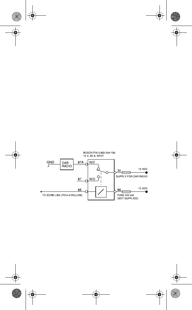
Car Radio Muting XCRM
The car kit offers a feature that can mute the car radio
automatically during a conversation. This feature is con-
venient and provides for safer handsfree operation. When
in standby, the yellow wire (XCRM) is not grounded and the
car radio works normally, but during a call, the line is
grounded and the car radio is muted. Note that an auxiliary
relay or muting unit must be used when the car radio
doesn’t have a mute feature available.
When a relay is used, it is connected in series with the car
radio main supply. A 200 mA fuse should be used to
protect the XCRM output in event of a short circuit. Some
radios have separate supplies for amplifiers and motors,
and another for memory backup purposes. Very often
these radios also have a secret code system, which acti-
vates itself if a break in the memory supply is detected.
Be careful when installing the relay not to break the mem-
ory supply (usually marked ACC or +MEM), but to install the
relay in the main supply feed.
Another possibility is to use a special muting unit, which
mutes the radio by connecting load resistors (not included)
to the speaker lines of the car radio.
Note: The Car Radio Mute option might not interface with
certain OEM and Aftermarket car stereos due to differing
electronics.
Antenna Motor Control AMC
The Antenna Motor Control offers the option to retract a
power AM/FM cellular antenna when the phone is in the
CARK-91USANDH07.26.00.fm Page 7 Wednesday, July 26, 2000 1:56 PM
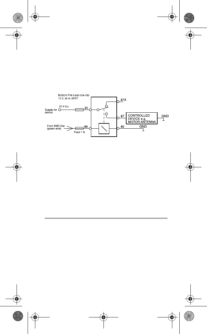
8
cradle (the system cable’s green wire). This allows the
phone to operate with the antenna without having to turn
on the car’s ignition. The voltage in this output is +12 V
whenever the phone is on. If the phone is turned off, the
voltage disappears. The maximum output current is 200 mA,
therefore for example the motorized antenna must be
controlled via a relay, see picture on next page.
Note: Please consult the dealer or car manufacturer about
antenna options available for your automobile. A dual mode
antenna is recommended when using a Nokia 6160
wireless phone.
All installations should take into account any special
requirements of the customer. However, should the cus-
tomer require an installation that is illegal or unsafe these
facts must be pointed out to the customer and a policy of
non-compliance adopted.
Te s t i n g
Once installed, the equipment should be tested to ensure
that it is operating satisfactorily and that the position of the
unit does not impair on the driver’s ability to control and
operate the vehicle in any way.
Use the phone to make a call when the vehicle is parked
with the engine running. During the call, switch off the
engine. Ensure that the phone is operational with the engine
running and with the engine switched off. For operating
information refer to the phone’s owner’s manual.
CARK-91USANDH07.26.00.fm Page 8 Wednesday, July 26, 2000 1:56 PM
9
NOTES
CARK-91USANDH07.26.00.fm Page 9 Wednesday, July 26, 2000 1:56 PM

10
NOTES
CARK-91USANDH07.26.00.fm Page 10 Wednesday, July 26, 2000 1:56 PM
11
© 1998 Nokia Mobile Phones. All rights reserved.
Nokia, Connecting People and the Original Accessories logos are
trademarks of Nokia Corporation and/or its affiliates.
Version 3 Printed in Canada 07/00 9358455
CARK-91USANDH07.26.00.fm Page 11 Wednesday, July 26, 2000 1:56 PM