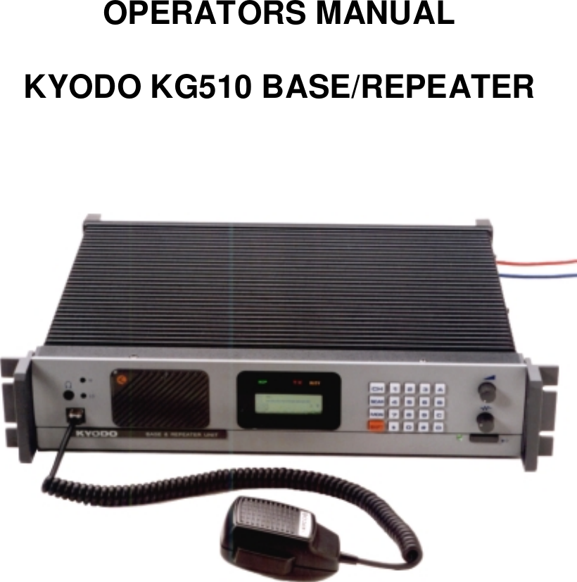
Midland Radio 710150C VHF Base Station/ Repeater User Manual users manual
Midland Radio Corporation VHF Base Station/ Repeater users manual
UserManual.wiki
>
Midland Radio
>
710150C User Manual
users manual
Navigation menu
Upload a User Manual
Namespaces
Wiki Guide
HTML
PDF
Info
Views
User Manual
Discussion / Help
Navigation
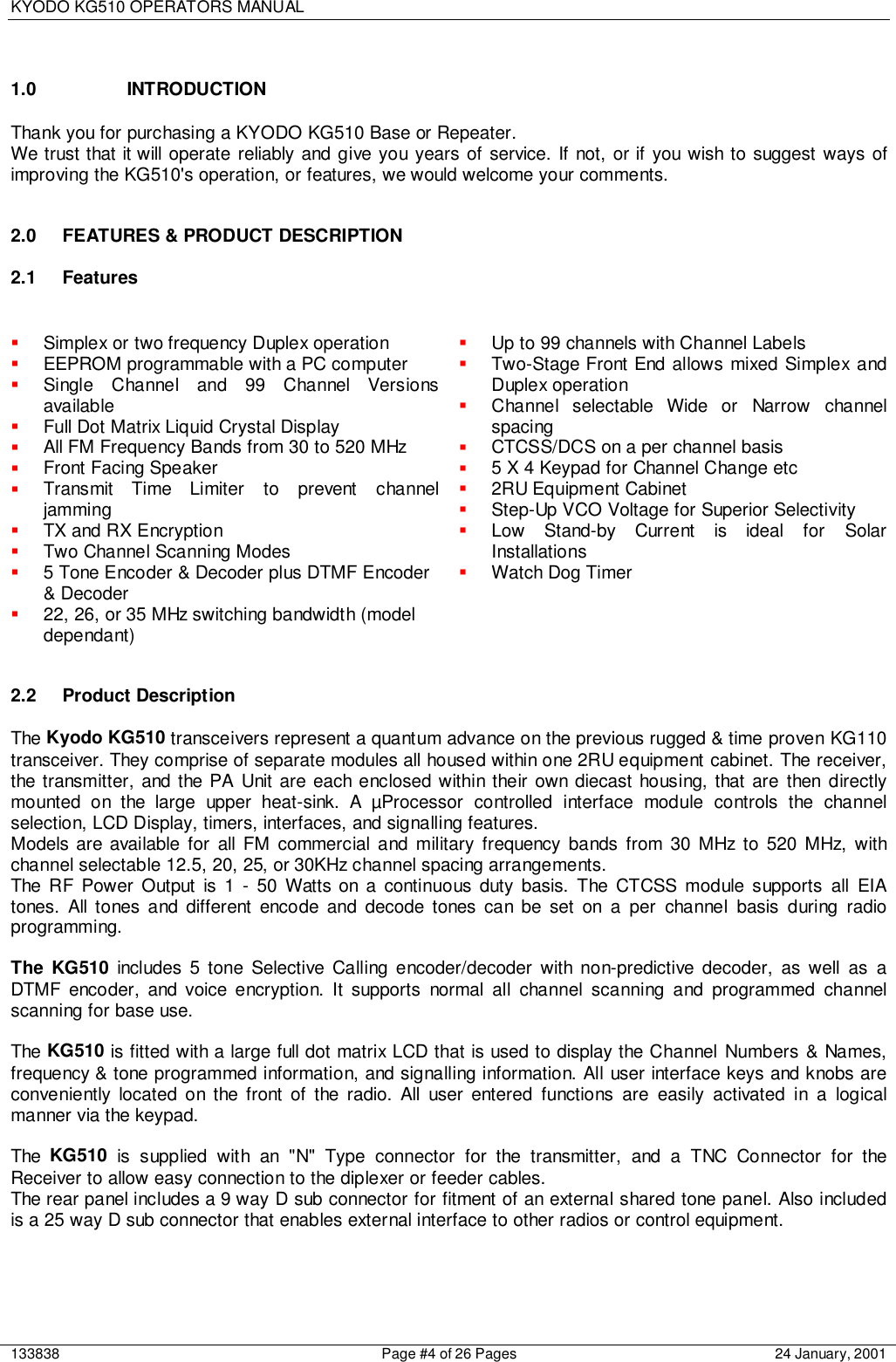
![KYODO KG510 OPERATORS MANUAL133838 Page #6 of 26 Pages 24 January, 20017.7.7.7. Transmit Mode Indicator LEDThe Transmit Mode Indicator LED will illuminate "TX" in Red colour whenever the KG510 istransmitting.8.8.8.8. Busy Mode Indicator LEDThe Busy Mode Indicator LED will illuminate "RX" in Green colour whenever the KG510 receivesa carrier signal on the selected channel that is greater then the Squelch setting.9.9.9.9. Keypad*The 5x4 key Keypad is used to enter channel selection, tone information, and other data into theKG510. Specific key sequences are described fully in section 4 of this document. It includes thefollowing keys: CH, SCAN, MON, SHIFT, 1, 2, 3, 4, 5, 6, 7, 8, 9, 0, , #, A, B, C, and D.10.10.10.10. Volume Control*The Volume Control is used to set the audio output level from the loudspeaker. Rotate this knobclockwise to increase the audio level, or counter-clockwise to reduce the audio level.11.11.11.11. Squelch Control*The Squelch Control is used to set the squelch threshold. Select a channel that is not being usedand slowly rotate this knob clockwise until the annoying background noise ceases. It may bedesirable to rotate this knob clockwise slightly past the squelch threshold to compensate forvarying background noise levels.12.12.12.12. Power ON/OFF SwitchThe Power ON/OFF Switch is used to switch the KG510 "ON" or "OFF". Press this knob to switchthe KG510 "ON". Press this knob again to switch the KG510 "OFF". This knob is slightly moredepressed when in the "ON" position.13.13.13.13. Power On Indicator LEDThe Power ON Indicator LED will illuminate in Green colour whenever the Power ON/OFF switchis switched to the "ON" position.14.14.14.14. Liquid Crystal Display (LCD)*The LCD comprises of four (4) lines each of which is capable of displaying twenty-one (21)characters.The first line, in normal operating condition, displays the strength of the signal being received onthe selected channel as a bar graph.The second line displays the strength of the transmitting power as a bar graph.The third line displays the selected channel number (up to four characters) in the first five lefthand character spaces, and displays the channel name (up to eight characters) in the next eightcharacter spaces.The following characters may be used in the channel name:0-9, A-Z, a-z, / + - # ! $ % ( ) = [ ] < > ? and spaceThis area of the LCD is left blank when channel names are not used.](https://usermanual.wiki/Midland-Radio/710150C/User-Guide-133838-Page-6.png)
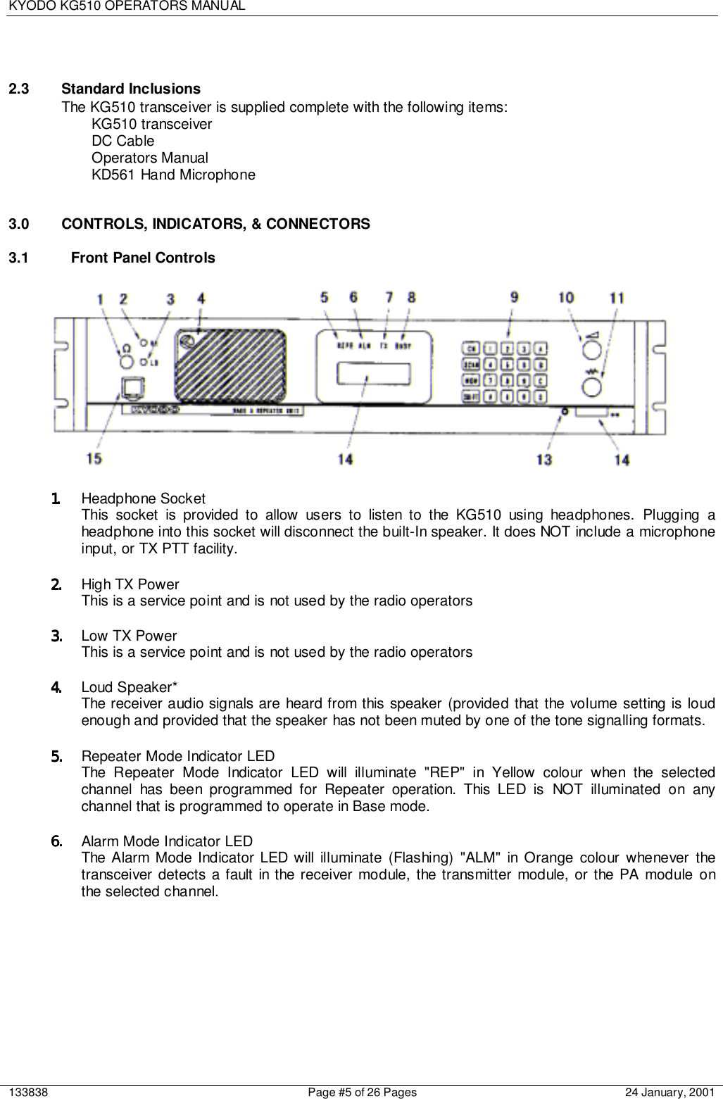
![KYODO KG510 OPERATORS MANUAL133838 Page #7 of 26 Pages 24 January, 2001The six character spaces on the right hand side of this line are used to display status symbols asfollows:a. The monitor status. --- symbol is b. The key lock status. --- symbol isc. The tone encode status. --- symbol is ϕd. The scan mode status. --- symbol is e. The high power transmit status. --- symbol is f. The [SHIFT] key status. ---This symbol is displayed whenever the [SHIFT] key is held depressed.The fourth line displays (in the left hand four character spaces) the type of tone signalling systemselected by the user. e.g. "5TON" means 5 Tone signalling while DTMF means Dual Tone MultiFrequency signalling.The right hand sixteen character spaces are used to display data that the user enters (e.g. 5Tone calling sequences). These character spaces are also used by the KG510 to displaymessages and information directed to the user.15.15.15.15. Microphone Input SocketConnect the supplied Kyodo KD561 microphone into this socket.* Not used on the Single Channel Model3.2 Rear Panel Connectors16.16.16.16. 25 way External Options Connector17.17.17.17. 9 way Programming Connector18.18.18.18. DC Input Fuse Holder19.19.19.19. 3 way DC Input Socket20.20.20.20. TX/Antenna Connector (N type)21.21.21.21. Ventilation Slots22.22.22.22. RX Connector (BNC type)](https://usermanual.wiki/Midland-Radio/710150C/User-Guide-133838-Page-7.png)
![KYODO KG510 OPERATORS MANUAL133838 Page #8 of 26 Pages 24 January, 20014.0 OPERATION4.1 Installation and ProgrammingAs the KG510 can be installed to operate as either a Base Station or as a Repeater, some of theinstructions in this document may apply to one application only, some may apply in both cases, whileothers may only apply if the particular function has been enabled during programming of the KG510.The KG510 must be programmed before it will operate correctly. This is best done by the equipmentsupplier or a competent radio tradesman. They will require the Kyodo 51BS programming software todo this correctly.It is important that the KG510 be correctly installed at its working location. It is recommended that thisbe done by a competent radio tradesman.As a minimum, it is necessary to:• Connect the DC Input power lead to a suitable 13.8 Volt Regulated DC Power supply thathas sufficient capacity. (Ensure that the DC Polarity is correct).• Connect the two antenna connectors to suitable antennas. (Ensure that the VSWR of theantennas is correct).• Insert the Kyodo KD561 Microphone into the microphone connector on the front panel.4.2 Basic Operation4.2.1 Switch OnSwitch the KG510 "ON" by pressing the knob (12) and then check that the LED indicator (13)is illuminated.4.2.2 Adjust the Volume SettingRotate the Volume Knob (10) clockwise (from the fully counterclockwise position) until theaudio level from the speaker is suitable.4.2.3 Adjust the Squelch SettingRotate the Squelch Knob clockwise (from the fully counter clockwise position) slowly until thebackground noise can no longer be heard. It is wise to slightly rotate the knob further in theclockwise direction (so that variations in the background noise level do not "break" thesquelch setting and cause annoying squelch noises to be heard from the speaker).4.2.4 Select the ChannelSelect the required channel by pressing the [SHIFT] key followed by the channel numberkeys within two seconds. E.g. [SHIFT] + [0] + [1] to select channel #1. The LCD Displayshould now display CH01 and (if programmed with a channel label) the channel name:"CH01 Kyodo-co".4.2.5 ReceivingYou should now be able to hear any radio traffic that occurs on channel #1 on the KG510. Itmay be necessary to further slightly adjust the Volume setting to suit your listeningrequirements.4.2.6 TransmittingDepending on the legal requirements in your country, and the operating requirements withinyour organisation, it may be necessary to announce your Call Sign, and will probably benecessary to announce the Call Sign of the party you are calling at the start of yourtransmission.When transmitting, it is necessary to hold the microphone about 75mm (3") from your mouthand speak clearly into the grill of the microphone.It is also necessary to press and hold the Press To Talk (PTT) bar on the side of themicrophone depressed while speaking into the microphone.](https://usermanual.wiki/Midland-Radio/710150C/User-Guide-133838-Page-8.png)
![KYODO KG510 OPERATORS MANUAL133838 Page #9 of 26 Pages 24 January, 20014.3 Front Panel OperationThis section describes most signalling and other advanced features that are available on the KG510Transceiver. The availability of some features is dependent on the programming of the transceiver.You may find it worthwhile to discuss these features in detail with your radio supplier to obtain a fullunderstanding of their benefits.4.3.1 Keypad OperationThe Keypad is the interface between the user and the KG510 and is used to enable ordisable various functions, and to enter the required data for signalling purposes.(5-Tone) or (DTMF) shown after the described feature indicates that the described featureapplies to the particular signalling format.The following keys are used for these purposes:[0] - [9] Entering new channel numbersEntering the "KILL" passwordEntering signalling encoding numbers (5-Tone) (DTMF)Entering DTMF numbers (DTMF)[A] Advancing the KG510 to the next higher channelEntering the signalling "A" tone (5-Tone) (DTMF)Encodes the "A" Tone (DTMF)[B] Advancing the KG510 to the next lower channelEntering the signalling "B" tone (5-Tone) (DTMF)Encodes the "B" Tone (DTMF)[C] Entering the signalling "C" tone (5-Tone) (DTMF)Encodes the "C" Tone (DTMF)[D] Entering the signalling "D" tone (5-Tone) (DTMF)Encodes the "D" Tone (DTMF)[ ] Displays the previously entered encode numbers (5-Tone)(DTMF)Encodes the " " -Tone (DTMF)[#] Encodes the signalling numbers that are displayed in the LCD display (5-Tone)(DTMF)Encodes the "#"-Tone (DTMF)[CH] Used with two channel numbers [0] - [9] to change the active channel on theKG510. E.g. [CH]+[9]+[0] will change the active channel to Channel 90 (providedCh 90 has been programmed into the KG510.[SCN] Used to place the KG510 into the "All-Scan" mode where the KG510 will scan allprogrammed channels. Pressing the [SCN] key again will cause the KG510 to exitfrom the "All-Scan" mode.[MON] Switches the KG510 between "Monitor ON" mode and "Monitor OFF" mode and isused to "Un-mute" the radio when using selective calling (depending on theprogramming of the KG510 transceiver).](https://usermanual.wiki/Midland-Radio/710150C/User-Guide-133838-Page-9.png)
![KYODO KG510 OPERATORS MANUAL133838 Page #10 of 26 Pages 24 January, 20014.3.2 Keypad Operation using the [SHIFT] KeySome of the KG510's features and how it operates can be changed by using the [SHIFT]key. To make these changes, it is necessary to firstly press the [SHIFT] key followed by theother keys within a two second timeframe.The following key sequences are used for these purposes:[SHIFT]+[0] Toggles the tone system between 5-Tone signalling and DTMF signalling.[SHIFT]+[1] Switches the LCD back-light ON or OFF.[SHIFT]+[2] Toggles the transmitting power between High power and Low power.[SHIFT]+[3] Invalid Key.[SHIFT]+[4] Toggles between "Single Tone Encoding" mode and "5-Tone" or "DTMF"signalling mode.[SHIFT]+[5] Invalid Key[SHIFT]+[6] Enters the KILL mode to allow entry of the KILL password.[SHIFT]+[7] Displays the programmed information for the selected (active) channel inthe LCD display.[SHIFT]+[8] Locks or Unlocks the KG510's Keypad.[SHIFT]+[9] Toggles the KG510 between "Normal Channel Scanning" mode and "PriorityChannel Scanning" mode.[SHIFT]+[A] Restores a channel to the Channel Scanning List. (The user must firstlyselect the channel to be restored as the active channel).[SHIFT]+[B] Invalid Key[SHIFT]+[C] Indicates to the KG510 that you have entered the last number of a DTMFencoding sequence.[SHIFT]+[D] Invalid Key[SHIFT]+[ ] Deletes the active channel from the Channel Scanning List.[SHIFT]+[#] Will attach the "R-Number" data to the active encode number and transmitthe whole sequence.[SHIFT]+[CH] Will start or stop the display of the TX and RX bar graphs in the LCD display.[SHIFT]+[SCN] Will place the KG510 in the Program Scan mode or exit from the ProgramScan mode.[SHIFT]+[MON] Invalid Key.](https://usermanual.wiki/Midland-Radio/710150C/User-Guide-133838-Page-10.png)
![KYODO KG510 OPERATORS MANUAL133838 Page #11 of 26 Pages 24 January, 20014.3.3 Changing ChannelsTo change to another channel, simply press the [CH] key followed by the number of therequired channel within two seconds.e.g. To select Channel # 8, press [CH] [0] [8]To select Channel # 99, press [CH] [9] [9]Note that it is always necessary to enter two digits for the Channel Number.The channel # location displayed in the LCD will become blank as soon as the [CH] key ispressed, and the cursor will blink at the location of the channel number, and display the newnumbers as they are entered.It is also possible to change channels by using the [A] and [B] keys instead of entering thechannel numbers.Pressing the [A] key will advance the channel to the next higher programmed channel, whilepressing [B] will advance the channel to the next lower programmed channel.Note that this action will ignore channels that have not been programmed into the KG510.Accordingly, the LCD display may appear to advance more than one channel if the missedchannel is not programmed into the KG510.4.4 SignallingThe KG510 includes some very sophisticated signalling capabilities. We suggest that you have yourradio supplier conduct some training on the use of these capabilities prior to using them.While it is possible to use these signalling capabilities in both repeater mode, and in base stationmode, many will only be useful in practice when the KG510 is used in base station configuration.The KG510 supports the 5-Tone sequential, and/or the DTMF, and the Single Tone signalling formats.The required signalling format(s) must be enabled when the KG510 is programmed.4.4.1 5-Tone Signalling4.4.1.1 Available Tones5-Tone signalling is commonly referred to as Selective Calling (or Selcall) and usuallycomprises of a series of 5 tones sequentially transmitted or received in accordance withcertain international standards. It is possible to use longer sequences to enhance thesignalling capabilities and to provide further functions.Accordingly, the KG510 will encode up to sixteen (16) tones and decode up to eight (8)tones.These tones can be any of the following:[0] - [9], and [A] - [D]The most recently entered tone can be recalled and deleted by pressing the [ ] keyrepeatedly.4.4.1.2 Entering a 5-Tone Encode SequenceWhen switched "ON", the KG510 carries out its self-test routine, and then waits ready toaccept 5-Tone encode numbers. Accordingly, it is only necessary to enter the required 5-Tone digits directly using the keypad, and then pressing the [#] key to transmit the 5-Tonesequence. (Up to sixteen digits can be entered).If it is necessary to enter the "R" number sequence to activate the repeater, the [SHIFT] keymust be pressed before pressing the [#] key.If a 5-Tone number is NOT displayed in the LCD, and the [#] key is pressed, then the KG510will recall the most recent 5-Tone number and transmit it.](https://usermanual.wiki/Midland-Radio/710150C/User-Guide-133838-Page-11.png)
![KYODO KG510 OPERATORS MANUAL133838 Page #12 of 26 Pages 24 January, 20014.4.1.3 Recalling the last encode sequencePressing the [ ] will recall the most recent 5-Tone encode sequence and display thesequence in the LCD display. Further presses of the [ ] key will delete the last digit of thesequence until all digits are deleted. In practice users will usually delete the last one or twodigits before entering the new digits.4.4.2 DTMF Signalling4.4.2.1 Available TonesThe following DTMF tones can be used:[0] - [9], [A] - [D], [ ], and [#]NOTE: Tone [B] is NOT available if the "Attach Decode No" field in the DTMF Encode Menuhas been set to "ON".Up to sixteen (16) DTMF digits can be encoded in one calling sequence.4.4.2.2 DTMF Tone EntryThere are two methods of entering DTMF tones. The specific tone encoding format isselected during the programming of the KG510 transceiver in the <Main Menu><EncodeSet><DTMF Encode><Attach Decode No.> field.4.4.2.2.1 Attach Decode No. "OFF" formatPressing the PTT lever first automatically selects the DTMF encoding format and allowsdirect entry of DTMF tones.Hold the PTT lever on the microphone depressed while pressing the required DTMF tones.The tones will be transmitted as the keys are being pressed.4.4.2.2.2 Attach Decode No. "ON" formatAttach Decode No. "ON" automatically encodes the users DTMF decode number after theencode number. This can be used for ANI purposes.Enter the required DTMF tones (up to sixteen tones except "B" tone) and then transmit thetotal tone sequence (including the users decode number) by pressing the [#] key. All toneswill be transmitted in one continuous sequence after pressing the [#] key.Pressing the [ ] key will delete the last entered number.Always confirm that the LCD is clear before proceeding as it may take up to 5 seconds forthe tones to be sent.e.g. Assume that your decode number is 12345, and that you wish to encode number 12346. You will input 12346, and then press the [#] key. The KG510 will encode 12346B12345. The called radio will display 12345 in their LCD indicating the calling party's number is 12345.NOTE: The "B" tone is used as the delimiter in this encoding format and therefore CANNOT be used as a DTMF tone.Pressing the [SHIFT] key and then the [#] will encode ONLY the encode number (and not thedecode number).](https://usermanual.wiki/Midland-Radio/710150C/User-Guide-133838-Page-12.png)
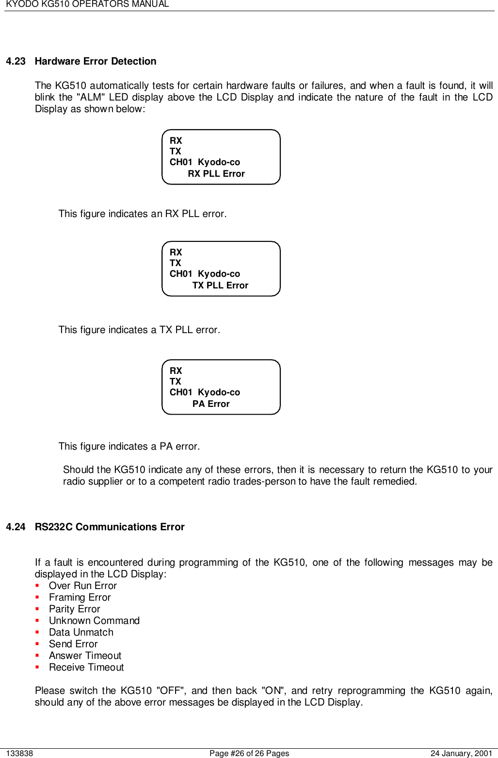
![KYODO KG510 OPERATORS MANUAL133838 Page #13 of 26 Pages 24 January, 20014.4.2.3 Redialling with DTMFIf during the programming of the KG510, the <Attach Decode No> field has been set to"OFF", the redialling function operates as follows:Press [SHIFT], then press [#] and the KG510 will redial the last encoded DTMF number.If during the programming of the KG510, the <Attach Decode No> field has been set to"ON", the redialling function operates as follows:Press [#] and the KG510 will redial the last encoded DTMF number with the KG510'sprogrammed decode number.Press [SHIFT], and then press [#] and the KG510 will redial the last encoded DTMF numberwithout the KG510's programmed decode number.4.4.2.4 Restoring the last DTMF number to the LCD DisplayIt is possible to restore the last encoded DTMF number to the LCD display, provided the<Attach Decode No> field has been set to "ON" during the programming of the KG510transceiver.Confirm that the LCD is NOT displaying any DTMF numbers, then press [✶] and the lastencoded DTMF number will be displayed in the LCD display.It is possible to edit this number at this time by pressing the [✶] key (which will erase the lastnumber) or by pressing the required keys to add additional numbers.4.4.2.5 Encoding DTMF numbers with the 5-Tone system enabledIt is possible to enter DTMF numbers even with the 5-Tone system enabled. This functionmust be enabled during the programming of the KG510 by setting the <DTMF Encode> fieldin the <5Tone Encode Menu> to "ENABLE".To enter a DTMF number (with 5-Tone signalling enabled), the user must press the PTTlever while entering the first DTMF number. Second and subsequent numbers do NOTrequire the PTT lever to be pressed provided all numbers are entered within a few seconds(before the display reverts to 5-Tone mode and displays "5TON" in the LCD display).4.4.3 Single Tone EncodingThe KG510 has the ability to encode one of six single tone frequencies for 1, 2, 3, or 4seconds. This function is enabled during programming of the KG510 by selecting the <SingleTone ON> field in the <Encode Menu> and setting the encode period.Press the [SHIFT] and the [4] keys to put the KG510 into Single Tone Encoding mode. "S1"and the tone frequency ("xxxxHz") will be displayed in the tone area of the LCD display forabout 4 seconds until the KG510 reverts back to the normal signalling mode.While the KG510 is in Single Tone Encoding mode, it is possible to advance to the next tonefrequency by pressing the [A] key, or to return to the previous tone by pressing the [B] key.Pressing the [#] key will encode the displayed tone (for the programmed time period) andautomatically exits the Single Tone Encoding mode and returns the KG510 to the normalsignalling mode.](https://usermanual.wiki/Midland-Radio/710150C/User-Guide-133838-Page-13.png)
![KYODO KG510 OPERATORS MANUAL133838 Page #14 of 26 Pages 24 January, 20014.4.4 KILL SignallingThe KG510 has the ability to transmit a specially coded signalling sequence that will disable("KILL") another radio. This feature is particularly useful when transceivers becomemisplaced, are stolen, if they are used in an incorrect manner, or if they are used for thewrong purposes.To prevent accidental or mischievous "KILLING" of radios, several security features are inplace.Firstly, the KG510 must have this function enabled during programming.Secondly, the user must know the required password and enter it correctly into the KG510,and,Thirdly, the user must know the required "KILL" number (of the radio to be "KILLED", andenter it correctly into the KG510.The "KILL" password has four numerical digits. [0] to [9].With 5-Tone signalling systems, the "KILL" number for a particular radio comprises of theradio's decode number + D + the radio's KILL number.With DTMF signalling systems, the "KILL" number for a particular radio comprises of theradio's decode number + A + the radio's KILL number. In the case of DTMF signalling, boththe decode number and the KILL number must have more than four digits.4.4.4.1 Kill Signalling OperationPress [SHIFT] and the press [6] to place the KG510 into the KILL mode.The LCD display will indicate that the KG510 is in the KILL modeEnter the required password by entering the correct four digit number.If the password has been correctly entered, the LCD display will show this message:Then enter the "KILL" data from the keyboard that comprises of the decode number + D +the KILL number of the radio to be "KILLED". (In the case of DTMF signalling, it will benecessary to substitute the "A" tone instead of the "D" tone).Then press [#] to transmit the data.RXTXCH01 Kyodo-co Kill Pass OKRXTXCH01 Kyodo-co Kill Pass --](https://usermanual.wiki/Midland-Radio/710150C/User-Guide-133838-Page-14.png)
![KYODO KG510 OPERATORS MANUAL133838 Page #15 of 26 Pages 24 January, 2001If the incorrect password has been entered, the LCD display will show the followingmessage:If you enter the "KILL" data prior to entering the KILL password, and then press the [#] key,the LCD display will show the following message:If the incorrect password has been entered more than the allowed number of tries, then theKG510 becomes disabled and the following message is displayed in the LCD display:In such cases, it is necessary to return the KG510 to your radio supplier to have the KG510repaired.4.5 ScanningThe KG510 is supplied with two scanning modes. These are All Channel Scan mode in which theKG510 will scan all channels that are programmed into the KG510, and the Program Channel Scanmode in which the KG510 will scan only the channels that have been designated during theprogramming of the KG510 transceiver.Furthermore, one HIGH priority, and one LOW priority scan channel can be set for each scan modeduring the programming of the radio.4.5.1 All Channel Scan OperationPressing the [SCAN] key places the KG510 into All Channel Scan mode and the Scan modesymbol " " is displayed in the LCD display. Also the LCD will display "All Scan Mode-in" fortwo seconds as shown below:RX ======TXCH01 Kyodo-co • All Scan Mode-inRXTXCH01 Kyodo-co Input Password Not ReadyRXTXCH01 Kyodo-co Kill Pass NG](https://usermanual.wiki/Midland-Radio/710150C/User-Guide-133838-Page-15.png)
![KYODO KG510 OPERATORS MANUAL133838 Page #16 of 26 Pages 24 January, 20014.5.2 Program Channel Scan OperationPressing the [SHIFT] and then the [SCAN] key places the KG510 into Program ChannelScan mode and the Scan mode symbol " " is displayed in the LCD display. Also the LCD willdisplay "PRG Scan Mode-in" for two seconds as shown below:4.5.3 Exiting All Channel Scan and Program Channel Scan modesPressing the [SCAN] key will take the KG510 out of either scanning mode and return theKG510 to normal mode. The scan symbol " " will be removed from the LCD display and theLCD will display "Scan Mode-out" for two seconds as shown below:4.5.4 Priority ScanningThe KG510 allows users to firstly enter the required scanning mode, and then they canenable Priority Scanning for the particular scanning mode chosen.Pressing the [SHIFT] key and then the [9] key places the KG510 into Priority Scanning modeas shown below:Pressing the [SHIFT] and the [9] keys again will take the KG510 out of Priority Scan modeand return to the Normal Scan mode as shown below:RX =====TXCH01 Kyodo-co • Normal ScanRX ======TXCH01 Kyodo-co • Priority ScanRX ======TXCH01 Kyodo-co Scan Mode-outRX ======TXCH01 Kyodo-co • Prg Scan Mode-in](https://usermanual.wiki/Midland-Radio/710150C/User-Guide-133838-Page-16.png)
![KYODO KG510 OPERATORS MANUAL133838 Page #17 of 26 Pages 24 January, 20014.5.5 Removing an Active Channel from the Scan ListIt is possible to temporarily delete an active channel from the scan list by pressing [SHIFT]and the [ ] key and holding the [SHIFT] and the [ ] keys depressed for more than onesecond. More than one channel can be deleted from the Scan list, provided that at least onechannel remains in the Scan List.A "beep" sound from the radio confirms correct deletion of the channel from the scan list.This function CANNOT be used in the Priority Scan mode.The KG510 automatically restores all channels to their respective scanning list as soon asthe KG510 exits from the scan mode.4.5.6 Restoring Channels to the Scan ListChannels can be restored to the scanning list without exiting from the scan mode bypressing the [SHIFT] key and pressing and holding the [A] key depressed for more than onesecond.This action will restore all channels to the scan list.This action CANNOT be used in the Priority Scan mode.4.6 Locking the KeypadPressing the [SHIFT] key and then the [8] key will lock all keys (except the [SHIFT] and [MON] keys)on the KG510's keypad to prevent accidental or inadvertent entry of data.After pressing the [SHIFT] and [8] keys the keypad becomes locked and the Key-Lock symbol isdisplayed in the LCD display. The display also shows "Key-Lock" for two seconds as shown below:Pressing [SHIFT] and [8] again will Unlock the keypad, remove the Key-Lock symbol from the LCDdisplay, and display "Key-Unlock" in the LCD display for two seconds as shown below:RX ======TXCH01 Kyodo-co Key UnlockRX ======TXCH01 Kyodo-co • Key Lock](https://usermanual.wiki/Midland-Radio/710150C/User-Guide-133838-Page-17.png)
![KYODO KG510 OPERATORS MANUAL133838 Page #18 of 26 Pages 24 January, 20014.7 Changing Tone Signalling SystemsIt is possible to switch the KG510's tone signalling system among 5-Tone sequential signalling,DTMF signalling and Non(No-Tone system) (providing the <Miscellaneous Menu> <Tone SystemChange> field was set to "ENABLE" during the programming of the KG510).Press [SHIFT] and keep depressed the [0] key for more than one second to change among 5-Tonesystem, DTMF system and Non and indicate new signalling system in the LCD display as follows:Pressing [SHIFT] and pressing the [0] key for more than one second again will change next thesignalling system and indicate new signalling system in the LCD display as shown below:4.8 Displaying the Channel InformationThe KG510 can display information pertaining to the selected channel (provided that the<Miscellaneous Menu> <Information Display> field was set to "ENABLE" during the programming ofthe radio.This information is:! The RX frequency of the selected channel.! The TX frequency of the selected channel.! The channel spacing for the selected channel (Wide or Narrow).! The operating mode for the selected channel (Base, Repeater, simplex, duplex)! The RX CTCSS/DCS tone for the selected channel (provided CTCSS/DCS has beenprogrammed for use on the selected channel).! The TX CTCSS/DCS tone for the selected channel (provided CTCSS/DCS has beenprogrammed for use on the selected channel).! The tone encoding format (providing 5-Tone signalling was selected during programming of theKG510).! The tone set (providing 5-Tone signalling was selected during programming of the KG510).! The ANI mode.! The tone decoding set (provided 5-Tone or DTMF signalling was selected during programming ofthe KG510).! The decode number (provided 5-Tone or DTMF signalling was selected during programming ofthe KG510).RX =======TXCH01 Kyodo-co System is NonRX ======TXCH01 Kyodo-co System is DTMF](https://usermanual.wiki/Midland-Radio/710150C/User-Guide-133838-Page-18.png)
![KYODO KG510 OPERATORS MANUAL133838 Page #19 of 26 Pages 24 January, 2001To view this information in the LCD display, firstly select the required channel. Then press the [SHIFT]key and then the [7] key. You will need to keep the [7] key pressed until the KG510 has cycled throughthe information steps.This function is NOT available if the <Miscellaneous Menu> <Information Display> field has been setto "DISABLE" during the programming of the KG510.4.9 Display of Received Tone Frequencies.It is possible to set the KG510 to display the received tone frequencies in the LCD display in the areanormally used to display the strength of the received signals.Press [SHIFT] and then press [D] to enable this function.Once enabled, the LCD will show "RCV" in the area of the LCD display that normally shows thestrength of the received signal, as well as "Tone Display on" for two seconds as shown below:Then, whenever a tone frequency is decoded, the frequency number will be displayed in the LCDdisplay to the right of "RCV" as shown below:Pressing the [SHIFT] key and then the [D] key once again will disable this function and return the LCDdisplay to normal as shown below:RCVTXCH01 Kyodo-co Tone Display OnRCV 12345TXCH01 Kyodo-co5TONRXTXCH01 Kyodo-co Tone Display Off](https://usermanual.wiki/Midland-Radio/710150C/User-Guide-133838-Page-19.png)
![KYODO KG510 OPERATORS MANUAL133838 Page #20 of 26 Pages 24 January, 20014.10 Bar Graph DisplaysThe KG510 will normally show the strength of the received signal to the right of "RX" in the LCDdisplay, and the strength of the transmitted signal to the right of "TX" in the LCD display, both in theform of a bar graph.This function can be disabled by pressing the [SHIFT] key and then the [CH] key. The LCD display willindicate "RX Display Off" and "TX Display Off" as shown below:Pressing the [SHIFT] key and then the [CH] key once again will return the KG510 to normal and theLCD display will show the normal bar graph display for both the RX signal strength and TX signalstrength.4.11 LCD Display Back LightThe LCD Display has a Back-Light to illuminate the display. It normally switches "ON" whenever anykey or the PTT lever is pressed, and will remain illuminated for five seconds after the most recent keypress. Some users may prefer the Back-Light to remain illuminated to assist viewing the LCD displayin poor viewing situations.Press the [SHIFT] key and then press the [1] key for more than one second and the LCD Back-lightwill remain illuminated.Once again, press the [SHIFT] key and then press the [1] key for more than one second and the LCDBack-light will revert to normal operation.4.12 Transmit Power ChangeIt is possible to change the KG510's transmit power from the high power setting to the low powersetting from the keypad and vice versa (provided that this function has been enabled during theprogramming of the KG510).To enable this function, the <Miscellaneous Menu> <TX Power Change> field must be set to"ENABLE".Press the [SHIFT] key and the [2] key and the KG510 will change from the high transmit power settingto the low transmit power setting, and the " “symbol will be removed from the third line of the LCDdisplay.Press the [SHIFT] key and the [2] key a second time, and the KG510 will change from the low transmitpower setting to the high transmit power setting, and the " " symbol will be displayed in the third line ofthe LCD display.If this function is NOT required, the <Miscellaneous Menu> <TX Power Change> field must be set to"DISABLE".RX Display OffTX Display OffCH01 Kyodo-co](https://usermanual.wiki/Midland-Radio/710150C/User-Guide-133838-Page-20.png)
![KYODO KG510 OPERATORS MANUAL133838 Page #21 of 26 Pages 24 January, 20014.13 Calling Party ID DisplayThe KG510 has the capability to display a calling radio's ID (ANI) number after being called. When theKG510 is called, "CALL" will be displayed on the fourth line of the LCD display (and continue to flash)and the calling radio's ID number will be displayed to the right of "CALL" as shown below:If the KG510 user presses the [#] key (when "CALL" is flashing and the caller's ID number isdisplayed), the KG510 will automatically call the identified radio.In the case of 5-Tone signalling systems, this function is enabled in the <5Tone Encode Menu><Encode Format> field, by selecting one of the following parameters:"Encode + B + Decode""Encode + A.Pause + Decode""Decode + A.Pause + Encode""Encode + ANI"In the case of DTMF signalling systems, this function is enabled by setting the <DTMF Encode Menu><Attach Decode No> field to "ON" during the programming of the KG510.4.14 Displaying any Radio's ID NumberThe KG510 has the capability to display any calling radio's ID (ANI) number. When the KG510receives an ANI number, "DISP" will be displayed on the fourth line of the LCD display (and continueto flash) and the radio's ID number will be displayed to the right of "DISP" as shown below:In the case of 5-Tone signalling systems, this function is enabled by setting the <5Tone DecodeMenu> <ANI Receive> field to "ON" during the programming of the KG510.In the case of DTMF signalling systems, this function is enabled by setting the <DTMF Decode Menu><ANI Receive> field to "ON" during the programming of the KG510.RXTXCH01 Kyodo-coCALL 12346RXTXCH01 Kyodo-coDISP 1234](https://usermanual.wiki/Midland-Radio/710150C/User-Guide-133838-Page-21.png)
![KYODO KG510 OPERATORS MANUAL133838 Page #22 of 26 Pages 24 January, 20014.15 Emergency Caller DisplayThe KG510 has the ability to accept and display emergency calls from other radios within the radiosystemThis function is enabled by setting the <Emg Call Receive> field to "ON" in the <5Tone Decode Menu>or <DTMF Decode Menu> during the programming of the radio.The calling (Emergency) radio must encode its emergency data in the following format:"000" + the calling radio's ID (decode number).This format applies to both 5 Tone and DTMF signalling systems.When the KG510 receives an emergency call, the KG510 will sound a warning tone from the speaker,display "EMG" (flashing) in the fourth line of the LCD display, and display the emergency radio's ID tothe right of "EMG" as shown below:Upon receipt of an emergency call, the KG510 will automatically respond to the emergency radio bysending the emergency radio's ID number to it.If the KG510 user presses the [#] key, the KG510 will resend the emergency radio's ID number.While the KG510 is in the Emergency Mode, all keys (except the [#] key) on the keyboard becomedisabled.Pressing the [SHIFT] key and the [ ] key will return the KG510 to the normal operating mode.4.16 Automatic Transmit in Repeater ModeThe KG510 can be programmed to automatically repeat valid incoming messages. Firstly, the activechannel of the KG510 must be programmed to operate as a repeater. It must then receive a carrierfrequency on the designated channel. If the KG510 has been programmed for CTCSS or DCSoperation, it must also receive a valid CTCSS or DCS tone. It will then automatically retransmit anyreceived signals.When the KG510 ceases to receive a carrier frequency, or a valid CTCSS or DCS tone, it activates the<Auto TX Reset Time> timer. This will keep the KG510 repeating (for up to 9.9 seconds depending onthe programming of the KG510), and allow other users with a valid CTCSS or DCS tone to access therepeater.RXTXCH01 Kyodo-coEMG 12346](https://usermanual.wiki/Midland-Radio/710150C/User-Guide-133838-Page-22.png)
![KYODO KG510 OPERATORS MANUAL133838 Page #23 of 26 Pages 24 January, 20014.17 TX Test ModeThe KG510 is provided with a TX (Transmit) Test Mode. When the KG510 is placed in the TX TestMode, it will transmit a carrier frequency modulated with a 1KHz tone on the selected active channel. Itis possible to change channels while in TX Test Mode.Pressing the [SHIFT] key and then the [B] key places the KG510 in TX Test Mode and displays themessage in the LCD as shown below:Pressing the [SHIFT] key and the [B] key a second time will return the KG510 to normal mode anddisplays the message in the LCD as shown below:4.18 Keypad Test ModeThe KG510 is provided with a Keypad Test Mode that allows the user to electrically test all keypadkeys as well as the PTT Key.Holding the [C] key pressed while switching the POWER SWITCH "ON" places the KG510 in KeypadTest Mode and displays the message in the LCD Display as shown below:Then press the keys to be tested one at a time. The respective key will be displayed in the LCD whenthe key is operating correctly.e.g. If you press the [CH] key, the LCD Display will indicate correct operation as shown below:Switch the KG510 "OFF" to exit this Keypad Test Mode.RXTXCH01 Kyodo-coTXT TX Test Mode-inRXTXCH01 Kyodo-coTXT TX Test Mode-out KEY TEST Please Key-in KEY TEST CH Key](https://usermanual.wiki/Midland-Radio/710150C/User-Guide-133838-Page-23.png)
![KYODO KG510 OPERATORS MANUAL133838 Page #24 of 26 Pages 24 January, 20014.19 Frequency Band Test ModeIt is possible to display the KG510's operating Frequency Band in the LCD display when in FrequencyBand Test Mode.Holding the [B] key pressed while switching the POWER SWITCH "ON" places the KG510 inFrequency Band Test Mode and displays the operating Frequency Band in the LCD Display as shownbelow:"40D" indicates the frequency band for a particular KG510 radio.Switch the KG510 "OFF" to exit the Frequency Band Test Mode.4.20 Starting MessageWhen the KG510 is Switched "ON", it will display a Starting Message in the LCD display for twoseconds. The default Starting Message (using all dots) is shown below:A personalised message for your business may be shown as the Starting Message. If you require apersonalised message, then it should be entered in the <Miscellaneous Menu> <Starting Message>field during the programming of the radio. Such a message is shown below: <PLL Band Check>> 40D OK••••••••••••••••••••••• <51BS V095 510>•••••••••••• Kyodo-co Japan <51BS V095 510>](https://usermanual.wiki/Midland-Radio/710150C/User-Guide-133838-Page-24.png)
![KYODO KG510 OPERATORS MANUAL133838 Page #25 of 26 Pages 24 January, 20014.21 Serial Number DisplayIt is possible to display the KG510's Serial Number in the LCD Display. To do so, the Serial Numbermust be entered into the <Configuration Menu> <Serial No.> field during the programming of theradio. The serial number can be up to eight characters long and can comprise of any of thesecharacters:"A - Z" & "0 - 9".Holding the [D] key pressed while switching the POWER SWITCH "ON" places the KG510 in SerialNumber Display Mode and displays the KG510's Serial Number in the LCD Display as shown below:Switch the KG510 "OFF" to exit from the Serial Number Display Mode.4.22 EEROM Data Check ModeAs soon as the KG510 is switched "ON", it will automatically read and check all the data in theEEROM.If this check finds damaged or corrupted data, the KG510 will automatically enter the ProgrammingMode and display the following message in the LCD Display:Should this happen, it is necessary to return the KG510 to your radio supplier or to a competent radiotrades-person who has the facilities to reprogram the KG510. Serial KY000727 EROM Data Error](https://usermanual.wiki/Midland-Radio/710150C/User-Guide-133838-Page-25.png)