Midland Radio 710150C VHF Base Station/ Repeater User Manual users manual
Midland Radio Corporation VHF Base Station/ Repeater users manual
users manual
OPERATORS MANUAL
KYODO KG510 BASE/REPEATER

KYODO KG510 OPERATORS MANUAL
133838 Page #2 of 26 Pages 24 January, 2001
CONTENTS
SECTION DESCRIPTION PAGE
1 INTRODUCTION 4
2 PRODUCT DESCRIPTION 4
2.1 Features 4
2.2 Product Description 4
2.3 Standard Inclusions 5
CONTROLS, INDICATORS, & CONNECTORS 5
3
3.1 Front Panel Controls 5-7
3.2 Rear Panel Connectors 7
OPERATION
4.1 Installation and Programming
8
4.2 Basic Operation 8
4.2.1 Switch On
4.2.2 Adjust the Volume Setting
4.2.3 Adjust the Squelch Setting
4.2.4 Select the Channel
4.2.5 Receiving
4.2.6 Transmitting
8
8
8
8
8
8
4
4.3 Front Panel Operation
4.3.1 Keypad Operation
4.3.2 Keypad Operation using the SHIFT Key
4.3.3 Changing Channels
9
9
10
11
4.4 Signalling 11
4.4.1 5-Tone Signalling 11
4.4.1.1 Available Tones 11
4.4.1.2 Entering 5-Tone Encoding Sequences 11
4.4.1.3 Recalling the Last Encode Sequence 12
4.4 2 DTMF Signalling 12
4.4.2.1 Available Tones 12
4.4.2.2 DTMF Tone Entry 12

KYODO KG510 OPERATORS MANUAL
133838 Page #3 of 26 Pages 24 January, 2001
CONTENTS
SECTION DESCRIPTION PAGE
4.4.2.3 Redialling with DTMF 13
4.4.2.4 Restoring the Last DTMF Numbers to the LCD Display 13
4.4 3 Single Tone Encoding 13
4.4.4 Kill Signalling 14
4.4.4.1 Kill Signalling Operation 14
4.5 Channel Scanning 15
4.5.1 All Channel Scan Operation 15
4.5 2 Program Channel Scan Operation 16
4.5.3 Exiting Scan Modes 16
4.5.4 Priority Scanning 16
4.5.5 Removing Channels from Scan List 17
4.5.6 Restoring Channels to the Scan List 17
4.6 Locking the Key Pad 17
4.7 Changing Tone Signalling Systems 18
4.8 Displaying Channel Information 18
4.9 Displaying Received Tone Frequencies 19
4.10 Bar Graph Displays 20
4.11 LCD Display Back Light 20
4.12 Transmit Power Change 20
4.13 Calling Party ID Display 21
4.14 Displaying any Radio's ID Number 21
4.15 Emergency Caller Display 22
4.16 Automatic Transmit in Repeater Mode 22
4.17 TX Test Mode 23
4.18 Key Pad Test Mode 23
4.19 Frequency Band Test Mode 24
4.20 Starting Message 24
4.21 Serial Number Display 25
4.22 EEPROM Data Check Mode 25
4.23 Hardware Error Detection 26
4.24 RS232C Communications Error Messages 26

KYODO KG510 OPERATORS MANUAL
133838 Page #4 of 26 Pages 24 January, 2001
1.0 INTRODUCTION
Thank you for purchasing a KYODO KG510 Base or Repeater.
We trust that it will operate reliably and give you years of service. If not, or if you wish to suggest ways of
improving the KG510's operation, or features, we would welcome your comments.
2.0 FEATURES & PRODUCT DESCRIPTION
2.1 Features
! Simplex or two frequency Duplex operation
! EEPROM programmable with a PC computer
! Single Channel and 99 Channel Versions
available
! Full Dot Matrix Liquid Crystal Display
! All FM Frequency Bands from 30 to 520 MHz
! Front Facing Speaker
! Transmit Time Limiter to prevent channel
jamming
! TX and RX Encryption
! Two Channel Scanning Modes
! 5 Tone Encoder & Decoder plus DTMF Encoder
& Decoder
! 22, 26, or 35 MHz switching bandwidth (model
dependant)
! Up to 99 channels with Channel Labels
! Two-Stage Front End allows mixed Simplex and
Duplex operation
! Channel selectable Wide or Narrow channel
spacing
! CTCSS/DCS on a per channel basis
! 5 X 4 Keypad for Channel Change etc
! 2RU Equipment Cabinet
! Step-Up VCO Voltage for Superior Selectivity
! Low Stand-by Current is ideal for Solar
Installations
! Watch Dog Timer
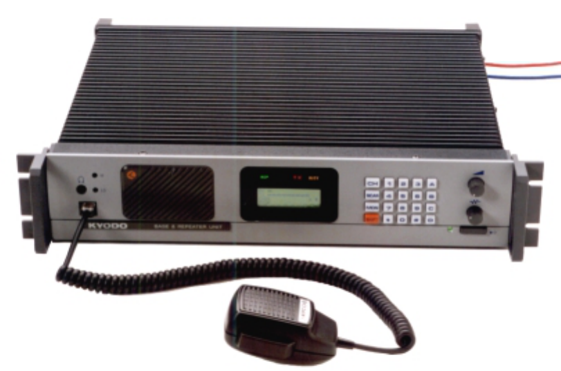
2.2 Product Description
The Kyodo KG510 transceivers represent a quantum advance on the previous rugged & time proven KG110
transceiver. They comprise of separate modules all housed within one 2RU equipment cabinet. The receiver,
the transmitter, and the PA Unit are each enclosed within their own diecast housing, that are then directly
mounted on the large upper heat-sink. A µProcessor controlled interface module controls the channel
selection, LCD Display, timers, interfaces, and signalling features.
Models are available for all FM commercial and military frequency bands from 30 MHz to 520 MHz, with
channel selectable 12.5, 20, 25, or 30KHz channel spacing arrangements.
The RF Power Output is 1 - 50 Watts on a continuous duty basis. The CTCSS module supports all EIA
tones. All tones and different encode and decode tones can be set on a per channel basis during radio
programming.
The KG510 includes 5 tone Selective Calling encoder/decoder with non-predictive decoder, as well as a
DTMF encoder, and voice encryption. It supports normal all channel scanning and programmed channel
scanning for base use.
The KG510 is fitted with a large full dot matrix LCD that is used to display the Channel Numbers & Names,
frequency & tone programmed information, and signalling information. All user interface keys and knobs are
conveniently located on the front of the radio. All user entered functions are easily activated in a logical
manner via the keypad.
The KG510 is supplied with an "N" Type connector for the transmitter, and a TNC Connector for the
Receiver to allow easy connection to the diplexer or feeder cables.
The rear panel includes a 9 way D sub connector for fitment of an external shared tone panel. Also included
is a 25 way D sub connector that enables external interface to other radios or control equipment.
KYODO KG510 OPERATORS MANUAL
133838 Page #5 of 26 Pages 24 January, 2001
2.3 Standard Inclusions
The KG510 transceiver is supplied complete with the following items:
KG510 transceiver
DC Cable
Operators Manual
KD561 Hand Microphone
3.0 CONTROLS, INDICATORS, & CONNECTORS
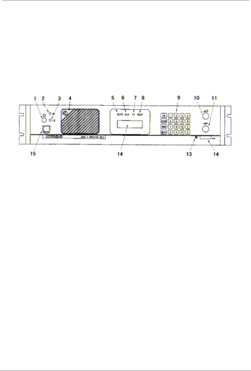
3.1 Front Panel Controls
1.
1.1.
1. Headphone Socket
This socket is provided to allow users to listen to the KG510 using headphones. Plugging a
headphone into this socket will disconnect the built-In speaker. It does NOT include a microphone
input, or TX PTT facility.
2.
2.2.
2. High TX Power
This is a service point and is not used by the radio operators
3.
3.3.
3. Low TX Power
This is a service point and is not used by the radio operators
4.
4.4.
4. Loud Speaker*
The receiver audio signals are heard from this speaker (provided that the volume setting is loud
enough and provided that the speaker has not been muted by one of the tone signalling formats.
5.
5.5.
5. Repeater Mode Indicator LED
The Repeater Mode Indicator LED will illuminate "REP" in Yellow colour when the selected
channel has been programmed for Repeater operation. This LED is NOT illuminated on any
channel that is programmed to operate in Base mode.
6.
6.6.
6. Alarm Mode Indicator LED
The Alarm Mode Indicator LED will illuminate (Flashing) "ALM" in Orange colour whenever the
transceiver detects a fault in the receiver module, the transmitter module, or the PA module on
the selected channel.

KYODO KG510 OPERATORS MANUAL
133838 Page #6 of 26 Pages 24 January, 2001
7.
7.7.
7. Transmit Mode Indicator LED
The Transmit Mode Indicator LED will illuminate "TX" in Red colour whenever the KG510 is
transmitting.
8.
8.8.
8. Busy Mode Indicator LED
The Busy Mode Indicator LED will illuminate "RX" in Green colour whenever the KG510 receives
a carrier signal on the selected channel that is greater then the Squelch setting.
9.
9.9.
9. Keypad*
The 5x4 key Keypad is used to enter channel selection, tone information, and other data into the
KG510. Specific key sequences are described fully in section 4 of this document. It includes the
following keys: CH, SCAN, MON, SHIFT, 1, 2, 3, 4, 5, 6, 7, 8, 9, 0, , #, A, B, C, and D.
10.
10.10.
10. Volume Control*
The Volume Control is used to set the audio output level from the loudspeaker. Rotate this knob
clockwise to increase the audio level, or counter-clockwise to reduce the audio level.
11.
11.11.
11. Squelch Control*
The Squelch Control is used to set the squelch threshold. Select a channel that is not being used
and slowly rotate this knob clockwise until the annoying background noise ceases. It may be
desirable to rotate this knob clockwise slightly past the squelch threshold to compensate for
varying background noise levels.
12.
12.12.
12. Power ON/OFF Switch
The Power ON/OFF Switch is used to switch the KG510 "ON" or "OFF". Press this knob to switch
the KG510 "ON". Press this knob again to switch the KG510 "OFF". This knob is slightly more
depressed when in the "ON" position.
13.
13.13.
13. Power On Indicator LED
The Power ON Indicator LED will illuminate in Green colour whenever the Power ON/OFF switch
is switched to the "ON" position.
14.
14.14.
14. Liquid Crystal Display (LCD)*
The LCD comprises of four (4) lines each of which is capable of displaying twenty-one (21)
characters.
The first line, in normal operating condition, displays the strength of the signal being received on
the selected channel as a bar graph.
The second line displays the strength of the transmitting power as a bar graph.
The third line displays the selected channel number (up to four characters) in the first five left
hand character spaces, and displays the channel name (up to eight characters) in the next eight
character spaces.
The following characters may be used in the channel name:
0-9, A-Z, a-z, / + - # ! $ % ( ) = [ ] < > ? and space
This area of the LCD is left blank when channel names are not used.
KYODO KG510 OPERATORS MANUAL
133838 Page #7 of 26 Pages 24 January, 2001
The six character spaces on the right hand side of this line are used to display status symbols as
follows:
a. The monitor status. --- symbol is
b. The key lock status. --- symbol is
c. The tone encode status. --- symbol is ϕ
d. The scan mode status. --- symbol is
e. The high power transmit status. --- symbol is
f. The [SHIFT] key status. ---This symbol is displayed whenever the [SHIFT] key is
held depressed.
The fourth line displays (in the left hand four character spaces) the type of tone signalling system
selected by the user. e.g. "5TON" means 5 Tone signalling while DTMF means Dual Tone Multi
Frequency signalling.
The right hand sixteen character spaces are used to display data that the user enters (e.g. 5
Tone calling sequences). These character spaces are also used by the KG510 to display
messages and information directed to the user.
15.
15.15.
15. Microphone Input Socket
Connect the supplied Kyodo KD561 microphone into this socket.
* Not used on the Single Channel Model
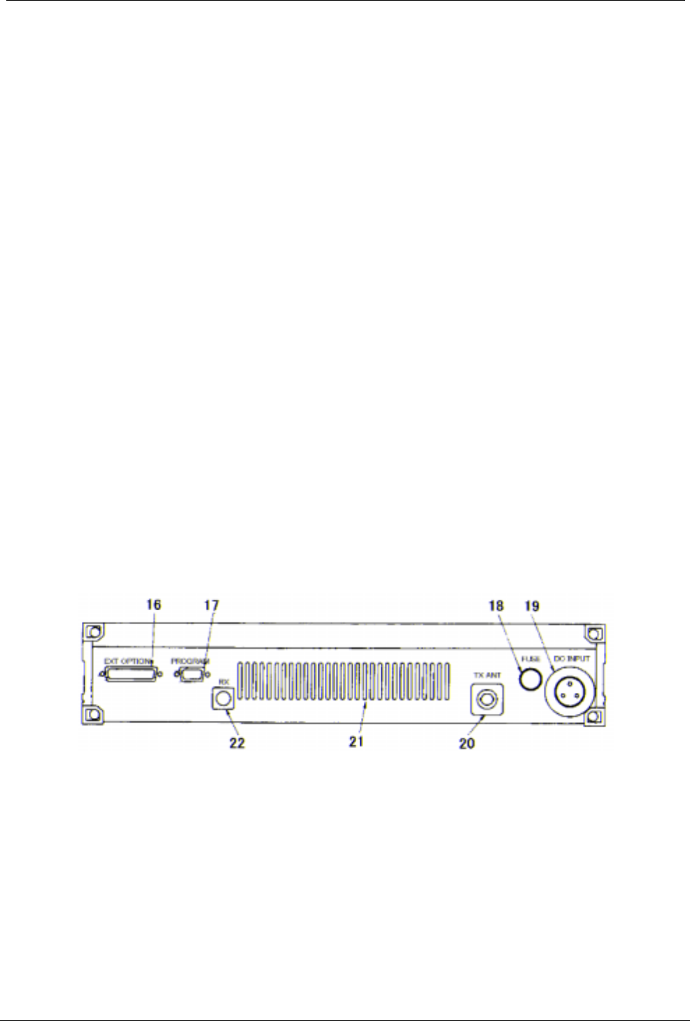
3.2 Rear Panel Connectors
16.
16.16.
16. 25 way External Options Connector
17.
17.17.
17. 9 way Programming Connector
18.
18.18.
18. DC Input Fuse Holder
19.
19.19.
19. 3 way DC Input Socket
20.
20.20.
20. TX/Antenna Connector (N type)
21.
21.21.
21. Ventilation Slots
22.
22.22.
22. RX Connector (BNC type)

KYODO KG510 OPERATORS MANUAL
133838 Page #8 of 26 Pages 24 January, 2001
4.0 OPERATION
4.1 Installation and Programming
As the KG510 can be installed to operate as either a Base Station or as a Repeater, some of the
instructions in this document may apply to one application only, some may apply in both cases, while
others may only apply if the particular function has been enabled during programming of the KG510.
The KG510 must be programmed before it will operate correctly. This is best done by the equipment
supplier or a competent radio tradesman. They will require the Kyodo 51BS programming software to
do this correctly.
It is important that the KG510 be correctly installed at its working location. It is recommended that this
be done by a competent radio tradesman.
As a minimum, it is necessary to:
• Connect the DC Input power lead to a suitable 13.8 Volt Regulated DC Power supply that
has sufficient capacity. (Ensure that the DC Polarity is correct).
• Connect the two antenna connectors to suitable antennas. (Ensure that the VSWR of the
antennas is correct).
• Insert the Kyodo KD561 Microphone into the microphone connector on the front panel.
4.2 Basic Operation
4.2.1 Switch On
Switch the KG510 "ON" by pressing the knob (12) and then check that the LED indicator (13)
is illuminated.
4.2.2 Adjust the Volume Setting
Rotate the Volume Knob (10) clockwise (from the fully counterclockwise position) until the
audio level from the speaker is suitable.
4.2.3 Adjust the Squelch Setting
Rotate the Squelch Knob clockwise (from the fully counter clockwise position) slowly until the
background noise can no longer be heard. It is wise to slightly rotate the knob further in the
clockwise direction (so that variations in the background noise level do not "break" the
squelch setting and cause annoying squelch noises to be heard from the speaker).
4.2.4 Select the Channel
Select the required channel by pressing the [SHIFT] key followed by the channel number
keys within two seconds. E.g. [SHIFT] + [0] + [1] to select channel #1. The LCD Display
should now display CH01 and (if programmed with a channel label) the channel name:
"CH01 Kyodo-co".
4.2.5 Receiving
You should now be able to hear any radio traffic that occurs on channel #1 on the KG510. It
may be necessary to further slightly adjust the Volume setting to suit your listening
requirements.
4.2.6 Transmitting
Depending on the legal requirements in your country, and the operating requirements within
your organisation, it may be necessary to announce your Call Sign, and will probably be
necessary to announce the Call Sign of the party you are calling at the start of your
transmission.
When transmitting, it is necessary to hold the microphone about 75mm (3") from your mouth
and speak clearly into the grill of the microphone.
It is also necessary to press and hold the Press To Talk (PTT) bar on the side of the
microphone depressed while speaking into the microphone.

KYODO KG510 OPERATORS MANUAL
133838 Page #9 of 26 Pages 24 January, 2001
4.3 Front Panel Operation
This section describes most signalling and other advanced features that are available on the KG510
Transceiver. The availability of some features is dependent on the programming of the transceiver.
You may find it worthwhile to discuss these features in detail with your radio supplier to obtain a full
understanding of their benefits.
4.3.1 Keypad Operation
The Keypad is the interface between the user and the KG510 and is used to enable or
disable various functions, and to enter the required data for signalling purposes.
(5-Tone) or (DTMF) shown after the described feature indicates that the described feature
applies to the particular signalling format.
The following keys are used for these purposes:
[0] - [9] Entering new channel numbers
Entering the "KILL" password
Entering signalling encoding numbers (5-Tone) (DTMF)
Entering DTMF numbers (DTMF)
[A] Advancing the KG510 to the next higher channel
Entering the signalling "A" tone (5-Tone) (DTMF)
Encodes the "A" Tone (DTMF)
[B] Advancing the KG510 to the next lower channel
Entering the signalling "B" tone (5-Tone) (DTMF)
Encodes the "B" Tone (DTMF)
[C] Entering the signalling "C" tone (5-Tone) (DTMF)
Encodes the "C" Tone (DTMF)
[D] Entering the signalling "D" tone (5-Tone) (DTMF)
Encodes the "D" Tone (DTMF)
[ ] Displays the previously entered encode numbers (5-Tone)
(DTMF)
Encodes the " " -Tone (DTMF)
[#] Encodes the signalling numbers that are displayed in the LCD display (5-Tone)
(DTMF)
Encodes the "#"-Tone (DTMF)
[CH] Used with two channel numbers [0] - [9] to change the active channel on the
KG510. E.g. [CH]+[9]+[0] will change the active channel to Channel 90 (provided
Ch 90 has been programmed into the KG510.
[SCN] Used to place the KG510 into the "All-Scan" mode where the KG510 will scan all
programmed channels. Pressing the [SCN] key again will cause the KG510 to exit
from the "All-Scan" mode.
[MON] Switches the KG510 between "Monitor ON" mode and "Monitor OFF" mode and is
used to "Un-mute" the radio when using selective calling (depending on the
programming of the KG510 transceiver).

KYODO KG510 OPERATORS MANUAL
133838 Page #10 of 26 Pages 24 January, 2001
4.3.2 Keypad Operation using the [SHIFT] Key
Some of the KG510's features and how it operates can be changed by using the [SHIFT]
key. To make these changes, it is necessary to firstly press the [SHIFT] key followed by the
other keys within a two second timeframe.
The following key sequences are used for these purposes:
[SHIFT]+[0] Toggles the tone system between 5-Tone signalling and DTMF signalling.
[SHIFT]+[1] Switches the LCD back-light ON or OFF.
[SHIFT]+[2] Toggles the transmitting power between High power and Low power.
[SHIFT]+[3] Invalid Key.
[SHIFT]+[4] Toggles between "Single Tone Encoding" mode and "5-Tone" or "DTMF"
signalling mode.
[SHIFT]+[5] Invalid Key
[SHIFT]+[6] Enters the KILL mode to allow entry of the KILL password.
[SHIFT]+[7] Displays the programmed information for the selected (active) channel in
the LCD display.
[SHIFT]+[8] Locks or Unlocks the KG510's Keypad.
[SHIFT]+[9] Toggles the KG510 between "Normal Channel Scanning" mode and "Priority
Channel Scanning" mode.
[SHIFT]+[A] Restores a channel to the Channel Scanning List. (The user must firstly
select the channel to be restored as the active channel).
[SHIFT]+[B] Invalid Key
[SHIFT]+[C] Indicates to the KG510 that you have entered the last number of a DTMF
encoding sequence.
[SHIFT]+[D] Invalid Key
[SHIFT]+[ ] Deletes the active channel from the Channel Scanning List.
[SHIFT]+[#] Will attach the "R-Number" data to the active encode number and transmit
the whole sequence.
[SHIFT]+[CH] Will start or stop the display of the TX and RX bar graphs in the LCD display.
[SHIFT]+[SCN] Will place the KG510 in the Program Scan mode or exit from the Program
Scan mode.
[SHIFT]+[MON] Invalid Key.

KYODO KG510 OPERATORS MANUAL
133838 Page #11 of 26 Pages 24 January, 2001
4.3.3 Changing Channels
To change to another channel, simply press the [CH] key followed by the number of the
required channel within two seconds.
e.g. To select Channel # 8, press [CH] [0] [8]
To select Channel # 99, press [CH] [9] [9]
Note that it is always necessary to enter two digits for the Channel Number.
The channel # location displayed in the LCD will become blank as soon as the [CH] key is
pressed, and the cursor will blink at the location of the channel number, and display the new
numbers as they are entered.
It is also possible to change channels by using the [A] and [B] keys instead of entering the
channel numbers.
Pressing the [A] key will advance the channel to the next higher programmed channel, while
pressing [B] will advance the channel to the next lower programmed channel.
Note that this action will ignore channels that have not been programmed into the KG510.
Accordingly, the LCD display may appear to advance more than one channel if the missed
channel is not programmed into the KG510.
4.4 Signalling
The KG510 includes some very sophisticated signalling capabilities. We suggest that you have your
radio supplier conduct some training on the use of these capabilities prior to using them.
While it is possible to use these signalling capabilities in both repeater mode, and in base station
mode, many will only be useful in practice when the KG510 is used in base station configuration.
The KG510 supports the 5-Tone sequential, and/or the DTMF, and the Single Tone signalling formats.
The required signalling format(s) must be enabled when the KG510 is programmed.
4.4.1 5-Tone Signalling
4.4.1.1 Available Tones
5-Tone signalling is commonly referred to as Selective Calling (or Selcall) and usually
comprises of a series of 5 tones sequentially transmitted or received in accordance with
certain international standards. It is possible to use longer sequences to enhance the
signalling capabilities and to provide further functions.
Accordingly, the KG510 will encode up to sixteen (16) tones and decode up to eight (8)
tones.
These tones can be any of the following:
[0] - [9], and [A] - [D]
The most recently entered tone can be recalled and deleted by pressing the [ ] key
repeatedly.
4.4.1.2 Entering a 5-Tone Encode Sequence
When switched "ON", the KG510 carries out its self-test routine, and then waits ready to
accept 5-Tone encode numbers. Accordingly, it is only necessary to enter the required 5-
Tone digits directly using the keypad, and then pressing the [#] key to transmit the 5-Tone
sequence. (Up to sixteen digits can be entered).
If it is necessary to enter the "R" number sequence to activate the repeater, the [SHIFT] key
must be pressed before pressing the [#] key.
If a 5-Tone number is NOT displayed in the LCD, and the [#] key is pressed, then the KG510
will recall the most recent 5-Tone number and transmit it.

KYODO KG510 OPERATORS MANUAL
133838 Page #12 of 26 Pages 24 January, 2001
4.4.1.3 Recalling the last encode sequence
Pressing the [ ] will recall the most recent 5-Tone encode sequence and display the
sequence in the LCD display. Further presses of the [ ] key will delete the last digit of the
sequence until all digits are deleted. In practice users will usually delete the last one or two
digits before entering the new digits.
4.4.2 DTMF Signalling
4.4.2.1 Available Tones
The following DTMF tones can be used:
[0] - [9], [A] - [D], [ ], and [#]
NOTE: Tone [B] is NOT available if the "Attach Decode No" field in the DTMF Encode Menu
has been set to "ON".
Up to sixteen (16) DTMF digits can be encoded in one calling sequence.
4.4.2.2 DTMF Tone Entry
There are two methods of entering DTMF tones. The specific tone encoding format is
selected during the programming of the KG510 transceiver in the <Main Menu><Encode
Set><DTMF Encode><Attach Decode No.> field.
4.4.2.2.1 Attach Decode No. "OFF" format
Pressing the PTT lever first automatically selects the DTMF encoding format and allows
direct entry of DTMF tones.
Hold the PTT lever on the microphone depressed while pressing the required DTMF tones.
The tones will be transmitted as the keys are being pressed.
4.4.2.2.2 Attach Decode No. "ON" format
Attach Decode No. "ON" automatically encodes the users DTMF decode number after the
encode number. This can be used for ANI purposes.
Enter the required DTMF tones (up to sixteen tones except "B" tone) and then transmit the
total tone sequence (including the users decode number) by pressing the [#] key. All tones
will be transmitted in one continuous sequence after pressing the [#] key.
Pressing the [ ] key will delete the last entered number.
Always confirm that the LCD is clear before proceeding as it may take up to 5 seconds for
the tones to be sent.
e.g. Assume that your decode number is 12345, and that you wish to encode number
12346. You will input 12346, and then press the [#] key. The KG510 will encode
12346B12345. The called radio will display 12345 in their LCD indicating the
calling party's number is 12345.
NOTE: The "B" tone is used as the delimiter in this encoding format and therefore CANNOT
be used as a DTMF tone.
Pressing the [SHIFT] key and then the [#] will encode ONLY the encode number (and not the
decode number).

KYODO KG510 OPERATORS MANUAL
133838 Page #13 of 26 Pages 24 January, 2001
4.4.2.3 Redialling with DTMF
If during the programming of the KG510, the <Attach Decode No> field has been set to
"OFF", the redialling function operates as follows:
Press [SHIFT], then press [#] and the KG510 will redial the last encoded DTMF number.
If during the programming of the KG510, the <Attach Decode No> field has been set to
"ON", the redialling function operates as follows:
Press [#] and the KG510 will redial the last encoded DTMF number with the KG510's
programmed decode number.
Press [SHIFT], and then press [#] and the KG510 will redial the last encoded DTMF number
without the KG510's programmed decode number.
4.4.2.4 Restoring the last DTMF number to the LCD Display
It is possible to restore the last encoded DTMF number to the LCD display, provided the
<Attach Decode No> field has been set to "ON" during the programming of the KG510
transceiver.
Confirm that the LCD is NOT displaying any DTMF numbers, then press [✶] and the last
encoded DTMF number will be displayed in the LCD display.
It is possible to edit this number at this time by pressing the [✶] key (which will erase the last
number) or by pressing the required keys to add additional numbers.
4.4.2.5 Encoding DTMF numbers with the 5-Tone system enabled
It is possible to enter DTMF numbers even with the 5-Tone system enabled. This function
must be enabled during the programming of the KG510 by setting the <DTMF Encode> field
in the <5Tone Encode Menu> to "ENABLE".
To enter a DTMF number (with 5-Tone signalling enabled), the user must press the PTT
lever while entering the first DTMF number. Second and subsequent numbers do NOT
require the PTT lever to be pressed provided all numbers are entered within a few seconds
(before the display reverts to 5-Tone mode and displays "5TON" in the LCD display).
4.4.3 Single Tone Encoding
The KG510 has the ability to encode one of six single tone frequencies for 1, 2, 3, or 4
seconds. This function is enabled during programming of the KG510 by selecting the <Single
Tone ON> field in the <Encode Menu> and setting the encode period.
Press the [SHIFT] and the [4] keys to put the KG510 into Single Tone Encoding mode. "S1"
and the tone frequency ("xxxxHz") will be displayed in the tone area of the LCD display for
about 4 seconds until the KG510 reverts back to the normal signalling mode.
While the KG510 is in Single Tone Encoding mode, it is possible to advance to the next tone
frequency by pressing the [A] key, or to return to the previous tone by pressing the [B] key.
Pressing the [#] key will encode the displayed tone (for the programmed time period) and
automatically exits the Single Tone Encoding mode and returns the KG510 to the normal
signalling mode.

KYODO KG510 OPERATORS MANUAL
133838 Page #14 of 26 Pages 24 January, 2001
4.4.4 KILL Signalling
The KG510 has the ability to transmit a specially coded signalling sequence that will disable
("KILL") another radio. This feature is particularly useful when transceivers become
misplaced, are stolen, if they are used in an incorrect manner, or if they are used for the
wrong purposes.
To prevent accidental or mischievous "KILLING" of radios, several security features are in
place.
Firstly, the KG510 must have this function enabled during programming.
Secondly, the user must know the required password and enter it correctly into the KG510,
and,
Thirdly, the user must know the required "KILL" number (of the radio to be "KILLED", and
enter it correctly into the KG510.
The "KILL" password has four numerical digits. [0] to [9].
With 5-Tone signalling systems, the "KILL" number for a particular radio comprises of the
radio's decode number + D + the radio's KILL number.
With DTMF signalling systems, the "KILL" number for a particular radio comprises of the
radio's decode number + A + the radio's KILL number. In the case of DTMF signalling, both
the decode number and the KILL number must have more than four digits.
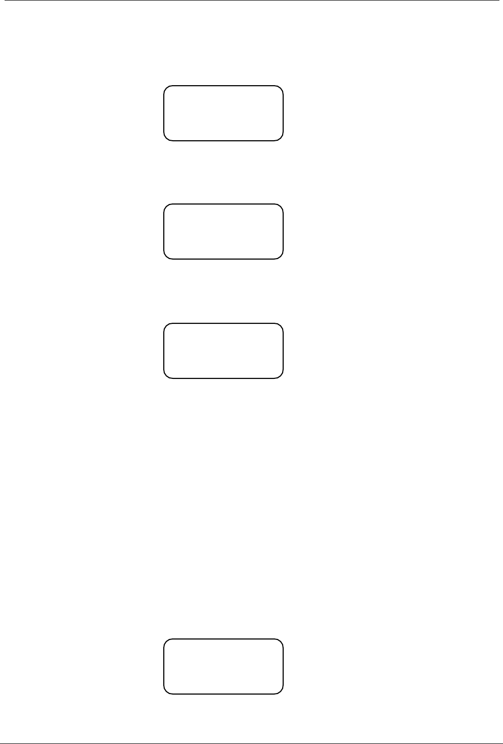
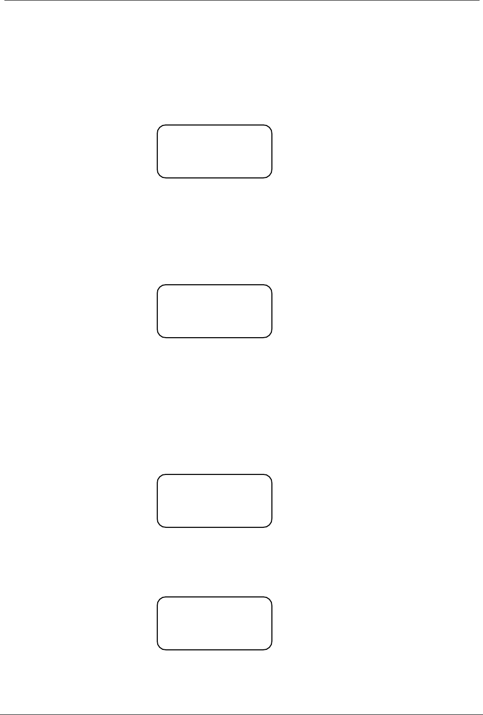
4.4.4.1 Kill Signalling Operation
Press [SHIFT] and the press [6] to place the KG510 into the KILL mode.
The LCD display will indicate that the KG510 is in the KILL mode
Enter the required password by entering the correct four digit number.
If the password has been correctly entered, the LCD display will show this message:
Then enter the "KILL" data from the keyboard that comprises of the decode number + D +
the KILL number of the radio to be "KILLED". (In the case of DTMF signalling, it will be
necessary to substitute the "A" tone instead of the "D" tone).
Then press [#] to transmit the data.
RX
TX
CH01 Kyodo-co
Kill Pass OK
RX
TX
CH01 Kyodo-co
Kill Pass --
KYODO KG510 OPERATORS MANUAL
133838 Page #15 of 26 Pages 24 January, 2001
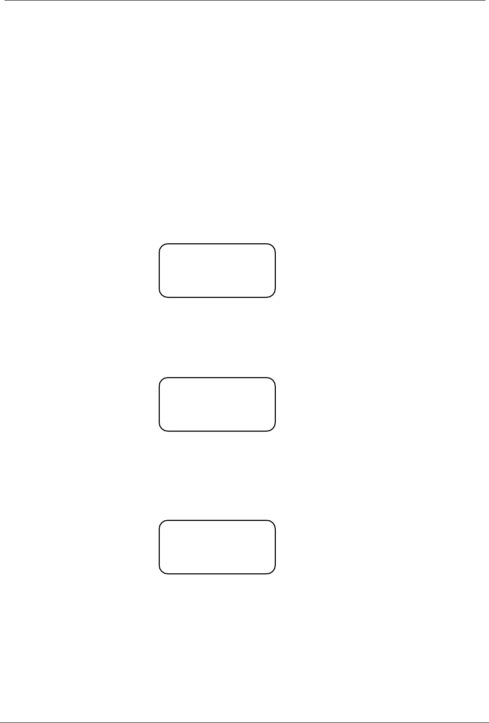
If the incorrect password has been entered, the LCD display will show the following
message:
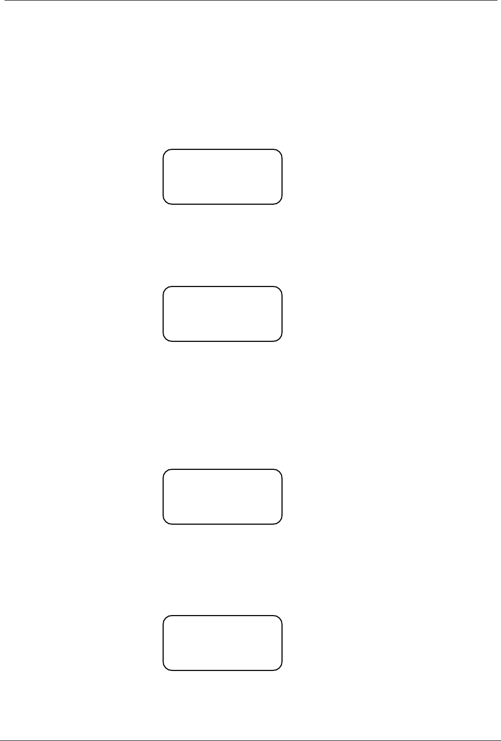
If you enter the "KILL" data prior to entering the KILL password, and then press the [#] key,
the LCD display will show the following message:
If the incorrect password has been entered more than the allowed number of tries, then the
KG510 becomes disabled and the following message is displayed in the LCD display:
In such cases, it is necessary to return the KG510 to your radio supplier to have the KG510
repaired.
4.5 Scanning
The KG510 is supplied with two scanning modes. These are All Channel Scan mode in which the
KG510 will scan all channels that are programmed into the KG510, and the Program Channel Scan
mode in which the KG510 will scan only the channels that have been designated during the
programming of the KG510 transceiver.
Furthermore, one HIGH priority, and one LOW priority scan channel can be set for each scan mode
during the programming of the radio.
4.5.1 All Channel Scan Operation
Pressing the [SCAN] key places the KG510 into All Channel Scan mode and the Scan mode
symbol " " is displayed in the LCD display. Also the LCD will display "All Scan Mode-in" for
two seconds as shown below:
RX ======
TX
CH01 Kyodo-co •
All Scan Mode-in
RX
TX
CH01 Kyodo-co
Input Password
Not Read
y
RX
TX
CH01 Kyodo-co
Kill Pass NG
KYODO KG510 OPERATORS MANUAL
133838 Page #16 of 26 Pages 24 January, 2001
4.5.2 Program Channel Scan Operation
Pressing the [SHIFT] and then the [SCAN] key places the KG510 into Program Channel
Scan mode and the Scan mode symbol " " is displayed in the LCD display. Also the LCD will
display "PRG Scan Mode-in" for two seconds as shown below:
4.5.3 Exiting All Channel Scan and Program Channel Scan modes
Pressing the [SCAN] key will take the KG510 out of either scanning mode and return the
KG510 to normal mode. The scan symbol " " will be removed from the LCD display and the
LCD will display "Scan Mode-out" for two seconds as shown below:
4.5.4 Priority Scanning
The KG510 allows users to firstly enter the required scanning mode, and then they can
enable Priority Scanning for the particular scanning mode chosen.
Pressing the [SHIFT] key and then the [9] key places the KG510 into Priority Scanning mode
as shown below:
Pressing the [SHIFT] and the [9] keys again will take the KG510 out of Priority Scan mode
and return to the Normal Scan mode as shown below:
RX =====
TX
CH01 Kyodo-co •
Normal Scan
RX ======
TX
CH01 Kyodo-co •
Priority Scan
RX ======
TX
CH01 Kyodo-co
Scan Mode-out
RX ======
TX
CH01 Kyodo-co •
Prg Scan Mode-in

KYODO KG510 OPERATORS MANUAL
133838 Page #17 of 26 Pages 24 January, 2001
4.5.5 Removing an Active Channel from the Scan List
It is possible to temporarily delete an active channel from the scan list by pressing [SHIFT]
and the [ ] key and holding the [SHIFT] and the [ ] keys depressed for more than one
second. More than one channel can be deleted from the Scan list, provided that at least one
channel remains in the Scan List.
A "beep" sound from the radio confirms correct deletion of the channel from the scan list.
This function CANNOT be used in the Priority Scan mode.
The KG510 automatically restores all channels to their respective scanning list as soon as
the KG510 exits from the scan mode.
4.5.6 Restoring Channels to the Scan List
Channels can be restored to the scanning list without exiting from the scan mode by
pressing the [SHIFT] key and pressing and holding the [A] key depressed for more than one
second.
This action will restore all channels to the scan list.
This action CANNOT be used in the Priority Scan mode.
4.6 Locking the Keypad
Pressing the [SHIFT] key and then the [8] key will lock all keys (except the [SHIFT] and [MON] keys)
on the KG510's keypad to prevent accidental or inadvertent entry of data.
After pressing the [SHIFT] and [8] keys the keypad becomes locked and the Key-Lock symbol is
displayed in the LCD display. The display also shows "Key-Lock" for two seconds as shown below:
Pressing [SHIFT] and [8] again will Unlock the keypad, remove the Key-Lock symbol from the LCD
display, and display "Key-Unlock" in the LCD display for two seconds as shown below:
RX ======
TX
CH01 Kyodo-co
Key Unlock
RX ======
TX
CH01 Kyodo-co •
Key Lock

KYODO KG510 OPERATORS MANUAL
133838 Page #18 of 26 Pages 24 January, 2001
4.7 Changing Tone Signalling Systems
It is possible to switch the KG510's tone signalling system among 5-Tone sequential signalling,
DTMF signalling and Non(No-Tone system) (providing the <Miscellaneous Menu> <Tone System
Change> field was set to "ENABLE" during the programming of the KG510).
Press [SHIFT] and keep depressed the [0] key for more than one second to change among 5-Tone
system, DTMF system and Non and indicate new signalling system in the LCD display as follows:
Pressing [SHIFT] and pressing the [0] key for more than one second again will change next the
signalling system and indicate new signalling system in the LCD display as shown below:
4.8 Displaying the Channel Information
The KG510 can display information pertaining to the selected channel (provided that the
<Miscellaneous Menu> <Information Display> field was set to "ENABLE" during the programming of
the radio.
This information is:
! The RX frequency of the selected channel.
! The TX frequency of the selected channel.
! The channel spacing for the selected channel (Wide or Narrow).
! The operating mode for the selected channel (Base, Repeater, simplex, duplex)
! The RX CTCSS/DCS tone for the selected channel (provided CTCSS/DCS has been
programmed for use on the selected channel).
! The TX CTCSS/DCS tone for the selected channel (provided CTCSS/DCS has been
programmed for use on the selected channel).
! The tone encoding format (providing 5-Tone signalling was selected during programming of the
KG510).
! The tone set (providing 5-Tone signalling was selected during programming of the KG510).
! The ANI mode.
! The tone decoding set (provided 5-Tone or DTMF signalling was selected during programming of
the KG510).
! The decode number (provided 5-Tone or DTMF signalling was selected during programming of
the KG510).
RX =======
TX
CH01 Kyodo-co
System is Non
RX ======
TX
CH01 Kyodo-co
System is DTMF
KYODO KG510 OPERATORS MANUAL
133838 Page #19 of 26 Pages 24 January, 2001
To view this information in the LCD display, firstly select the required channel. Then press the [SHIFT]
key and then the [7] key. You will need to keep the [7] key pressed until the KG510 has cycled through
the information steps.
This function is NOT available if the <Miscellaneous Menu> <Information Display> field has been set
to "DISABLE" during the programming of the KG510.
4.9 Display of Received Tone Frequencies.
It is possible to set the KG510 to display the received tone frequencies in the LCD display in the area
normally used to display the strength of the received signals.
Press [SHIFT] and then press [D] to enable this function.
Once enabled, the LCD will show "RCV" in the area of the LCD display that normally shows the
strength of the received signal, as well as "Tone Display on" for two seconds as shown below:
Then, whenever a tone frequency is decoded, the frequency number will be displayed in the LCD
display to the right of "RCV" as shown below:
Pressing the [SHIFT] key and then the [D] key once again will disable this function and return the LCD
display to normal as shown below:
RCV
TX
CH01 Kyodo-co
Tone Display On
RCV 12345
TX
CH01 Kyodo-co
5TON
RX
TX
CH01 Kyodo-co
Tone Display Off

KYODO KG510 OPERATORS MANUAL
133838 Page #20 of 26 Pages 24 January, 2001
4.10 Bar Graph Displays
The KG510 will normally show the strength of the received signal to the right of "RX" in the LCD
display, and the strength of the transmitted signal to the right of "TX" in the LCD display, both in the
form of a bar graph.
This function can be disabled by pressing the [SHIFT] key and then the [CH] key. The LCD display will
indicate "RX Display Off" and "TX Display Off" as shown below:
Pressing the [SHIFT] key and then the [CH] key once again will return the KG510 to normal and the
LCD display will show the normal bar graph display for both the RX signal strength and TX signal
strength.
4.11 LCD Display Back Light
The LCD Display has a Back-Light to illuminate the display. It normally switches "ON" whenever any
key or the PTT lever is pressed, and will remain illuminated for five seconds after the most recent key
press. Some users may prefer the Back-Light to remain illuminated to assist viewing the LCD display
in poor viewing situations.
Press the [SHIFT] key and then press the [1] key for more than one second and the LCD Back-light
will remain illuminated.
Once again, press the [SHIFT] key and then press the [1] key for more than one second and the LCD
Back-light will revert to normal operation.
4.12 Transmit Power Change
It is possible to change the KG510's transmit power from the high power setting to the low power
setting from the keypad and vice versa (provided that this function has been enabled during the
programming of the KG510).
To enable this function, the <Miscellaneous Menu> <TX Power Change> field must be set to
"ENABLE".
Press the [SHIFT] key and the [2] key and the KG510 will change from the high transmit power setting
to the low transmit power setting, and the " “symbol will be removed from the third line of the LCD
display.
Press the [SHIFT] key and the [2] key a second time, and the KG510 will change from the low transmit
power setting to the high transmit power setting, and the " " symbol will be displayed in the third line of
the LCD display.
If this function is NOT required, the <Miscellaneous Menu> <TX Power Change> field must be set to
"DISABLE".
RX Display Off
TX Display Off
CH01 Kyodo-co

KYODO KG510 OPERATORS MANUAL
133838 Page #21 of 26 Pages 24 January, 2001
4.13 Calling Party ID Display
The KG510 has the capability to display a calling radio's ID (ANI) number after being called. When the
KG510 is called, "CALL" will be displayed on the fourth line of the LCD display (and continue to flash)
and the calling radio's ID number will be displayed to the right of "CALL" as shown below:
If the KG510 user presses the [#] key (when "CALL" is flashing and the caller's ID number is
displayed), the KG510 will automatically call the identified radio.
In the case of 5-Tone signalling systems, this function is enabled in the <5Tone Encode Menu>
<Encode Format> field, by selecting one of the following parameters:
"Encode + B + Decode"
"Encode + A.Pause + Decode"
"Decode + A.Pause + Encode"
"Encode + ANI"
In the case of DTMF signalling systems, this function is enabled by setting the <DTMF Encode Menu>
<Attach Decode No> field to "ON" during the programming of the KG510.
4.14 Displaying any Radio's ID Number
The KG510 has the capability to display any calling radio's ID (ANI) number. When the KG510
receives an ANI number, "DISP" will be displayed on the fourth line of the LCD display (and continue
to flash) and the radio's ID number will be displayed to the right of "DISP" as shown below:
In the case of 5-Tone signalling systems, this function is enabled by setting the <5Tone Decode
Menu> <ANI Receive> field to "ON" during the programming of the KG510.
In the case of DTMF signalling systems, this function is enabled by setting the <DTMF Decode Menu>
<ANI Receive> field to "ON" during the programming of the KG510.
RX
TX
CH01 Kyodo-co
CALL 12346
RX
TX
CH01 Kyodo-co
DISP 1234

KYODO KG510 OPERATORS MANUAL
133838 Page #22 of 26 Pages 24 January, 2001
4.15 Emergency Caller Display
The KG510 has the ability to accept and display emergency calls from other radios within the radio
system
This function is enabled by setting the <Emg Call Receive> field to "ON" in the <5Tone Decode Menu>
or <DTMF Decode Menu> during the programming of the radio.
The calling (Emergency) radio must encode its emergency data in the following format:
"000" + the calling radio's ID (decode number).
This format applies to both 5 Tone and DTMF signalling systems.
When the KG510 receives an emergency call, the KG510 will sound a warning tone from the speaker,
display "EMG" (flashing) in the fourth line of the LCD display, and display the emergency radio's ID to
the right of "EMG" as shown below:
Upon receipt of an emergency call, the KG510 will automatically respond to the emergency radio by
sending the emergency radio's ID number to it.
If the KG510 user presses the [#] key, the KG510 will resend the emergency radio's ID number.
While the KG510 is in the Emergency Mode, all keys (except the [#] key) on the keyboard become
disabled.
Pressing the [SHIFT] key and the [ ] key will return the KG510 to the normal operating mode.
4.16 Automatic Transmit in Repeater Mode
The KG510 can be programmed to automatically repeat valid incoming messages. Firstly, the active
channel of the KG510 must be programmed to operate as a repeater. It must then receive a carrier
frequency on the designated channel. If the KG510 has been programmed for CTCSS or DCS
operation, it must also receive a valid CTCSS or DCS tone. It will then automatically retransmit any
received signals.
When the KG510 ceases to receive a carrier frequency, or a valid CTCSS or DCS tone, it activates the
<Auto TX Reset Time> timer. This will keep the KG510 repeating (for up to 9.9 seconds depending on
the programming of the KG510), and allow other users with a valid CTCSS or DCS tone to access the
repeater.
RX
TX
CH01 Kyodo-co
EMG 12346
KYODO KG510 OPERATORS MANUAL
133838 Page #23 of 26 Pages 24 January, 2001
4.17 TX Test Mode
The KG510 is provided with a TX (Transmit) Test Mode. When the KG510 is placed in the TX Test
Mode, it will transmit a carrier frequency modulated with a 1KHz tone on the selected active channel. It
is possible to change channels while in TX Test Mode.
Pressing the [SHIFT] key and then the [B] key places the KG510 in TX Test Mode and displays the
message in the LCD as shown below:
Pressing the [SHIFT] key and the [B] key a second time will return the KG510 to normal mode and
displays the message in the LCD as shown below:
4.18 Keypad Test Mode
The KG510 is provided with a Keypad Test Mode that allows the user to electrically test all keypad
keys as well as the PTT Key.
Holding the [C] key pressed while switching the POWER SWITCH "ON" places the KG510 in Keypad
Test Mode and displays the message in the LCD Display as shown below:
Then press the keys to be tested one at a time. The respective key will be displayed in the LCD when
the key is operating correctly.
e.g. If you press the [CH] key, the LCD Display will indicate correct operation as shown below:
Switch the KG510 "OFF" to exit this Keypad Test Mode.
RX
TX
CH01 Kyodo-co
TXT TX Test Mode-in
RX
TX
CH01 Kyodo-co
TXT TX Test Mode-out
KEY TEST
Please Key-in
KEY TEST
CH Key

KYODO KG510 OPERATORS MANUAL
133838 Page #24 of 26 Pages 24 January, 2001
4.19 Frequency Band Test Mode
It is possible to display the KG510's operating Frequency Band in the LCD display when in Frequency
Band Test Mode.
Holding the [B] key pressed while switching the POWER SWITCH "ON" places the KG510 in
Frequency Band Test Mode and displays the operating Frequency Band in the LCD Display as shown
below:
"40D" indicates the frequency band for a particular KG510 radio.
Switch the KG510 "OFF" to exit the Frequency Band Test Mode.
4.20 Starting Message
When the KG510 is Switched "ON", it will display a Starting Message in the LCD display for two
seconds. The default Starting Message (using all dots) is shown below:
A personalised message for your business may be shown as the Starting Message. If you require a
personalised message, then it should be entered in the <Miscellaneous Menu> <Starting Message>
field during the programming of the radio. Such a message is shown below:
<PLL Band Check>>
40D OK
•••••••••••
•••••••••••
• <51BS V095 510>•
•••••••••••
Kyodo-co Japan
<51BS V095 510>

KYODO KG510 OPERATORS MANUAL
133838 Page #25 of 26 Pages 24 January, 2001
4.21 Serial Number Display
It is possible to display the KG510's Serial Number in the LCD Display. To do so, the Serial Number
must be entered into the <Configuration Menu> <Serial No.> field during the programming of the
radio. The serial number can be up to eight characters long and can comprise of any of these
characters:
"A - Z" & "0 - 9".
Holding the [D] key pressed while switching the POWER SWITCH "ON" places the KG510 in Serial
Number Display Mode and displays the KG510's Serial Number in the LCD Display as shown below:
Switch the KG510 "OFF" to exit from the Serial Number Display Mode.
4.22 EEROM Data Check Mode
As soon as the KG510 is switched "ON", it will automatically read and check all the data in the
EEROM.
If this check finds damaged or corrupted data, the KG510 will automatically enter the Programming
Mode and display the following message in the LCD Display:
Should this happen, it is necessary to return the KG510 to your radio supplier or to a competent radio
trades-person who has the facilities to reprogram the KG510.
Serial KY000727
EROM Data Error

KYODO KG510 OPERATORS MANUAL
133838 Page #26 of 26 Pages 24 January, 2001
4.23 Hardware Error Detection
The KG510 automatically tests for certain hardware faults or failures, and when a fault is found, it will
blink the "ALM" LED display above the LCD Display and indicate the nature of the fault in the LCD
Display as shown below:
This figure indicates an RX PLL error.
This figure indicates a TX PLL error.
This figure indicates a PA error.
Should the KG510 indicate any of these errors, then it is necessary to return the KG510 to your
radio supplier or to a competent radio trades-person to have the fault remedied.
4.24 RS232C Communications Error
If a fault is encountered during programming of the KG510, one of the following messages may be
displayed in the LCD Display:
! Over Run Error
! Framing Error
! Parity Error
! Unknown Command
! Data Unmatch
! Send Error
! Answer Timeout
! Receive Timeout
Please switch the KG510 "OFF", and then back "ON", and retry reprogramming the KG510 again,
should any of the above error messages be displayed in the LCD Display.
RX
TX
CH01 Kyodo-co
RX PLL Error
RX
TX
CH01 Kyodo-co
TX PLL Error
RX
TX
CH01 Kyodo-co
PA Error