MilDef Crete RT9 13" Notebook User Manual UM
MilDef Crete Inc. 13" Notebook UM
UserManual.wiki
>
MilDef Crete
>
RT9 User Manual
Users Manual
Navigation menu
Upload a User Manual
Namespaces
Wiki Guide
HTML
PDF
Info
Views
User Manual
Discussion / Help
Navigation


![Chapter Two - 12Operating Information Keyboard Backlight (Optional) Press [Fn] [F5] key for approximately 1 second to turn the keyboard backlight ON or OFF. Hard Disk Drive (HDD) The Hard Disk Drive (HDD) is a 2.5” type/ 9.5mm height standard SATA interface data storage device. HDD and ODD are removable. This design provides convenience and security. They can ONLY be removed when the power is OFF. ODD (Optical Disk Device) There is a 5.25” type/ 12.7mm height standard SATA interface ODD. The actual device will depend on the model you purchased. The ODD may be used as a boot device if properly set in the BIOS. The ODD accepts a variety of standard 12cm CDs, DVD-ROM (Single Layer, Dual Layer), DVD-Video, DVD-R*10 (1.4 GB, 2.8 GB, 4.7GB), DVD-RW (Ver.1.1/1.2 1.4 Gx`B, 2.8 GB, 4.7 GB, 9.4 GB), DVD-R DL (8.5 GB), DVD-RAM (1.4 GB, 2.8 GB, 4.7 GB, 9.4 GB), +R (4.7 GB), +R DL (8.5 GB), +RW (4.7 GB), CD-Audio, CD-ROM (XA compatible), CD-R, Photo CD (multiple session compatible), Video CD, CD EXTRA, CD-RW, CD-TEXT and etc. Do not use the IDE-interface ODD; it may cause the computer malfunction. Note: NEVER drop your HDD, ODD or expose them to high temperature, high humidity, or any hazardous environment. NEVER try to disassemble the module. Static discharge may destroy your device and data. Always pick up the modules by touching the case only.](https://usermanual.wiki/MilDef-Crete/RT9/User-Guide-1316477-Page-22.png)
![Chapter Four - 26BIOS SetupChapter Four- BIOS Setup Press [F2] at boot up to enter BIOS setup. Use arrow keys to select options and [+/-] to modify them. When finished, move to” Exit” and press [Enter] then confirm save by pressing [Y]. Main Menu Phoenix SecureCore (tm) Setup Utility Main Advanced Security Boot Exit Item Specific Help System Time: [15:48:04] System Date: [10/02/2010] ► SATA Port 1 [Auto] ► SATA Port 2 [Auto] System Memory: 632 KB Extended Memory: 1012736KB <Tab>, <Shift-Tab>, or <Enter> selects field. F1 Help ↑↓ Select Item –/+ Change Values F9 Setup Defaults Esc Exit ↔ Menu Enter Select ► Sub-Menu F10 Save and Exit Main Menu Selections You can make the following selections on the Main Menu. Use the sub-menus for other selections. Feature Options Description System Time HH:MM:SS Set the system time Hour, Minute, Second. System Date MM/DD/YYYY Set the system date Month, Day, Year. SATA Port 1~2 None Auto-detect the device, then show the device. Note: ¾ The contents may vary depending on computer configurations.](https://usermanual.wiki/MilDef-Crete/RT9/User-Guide-1316477-Page-36.png)
![Chapter Four - 28BIOS Setup SATA Port 1 Sub-Menu Phoenix SecureCore (tm) Setup Utility Main SATA Port 1 [Auto)] Item Specific Help Type: [Auto] LBA Format Total Sectors: 78140160 Maximum Capacity: 40008MB Multi-Sector Transfers: [16 Sectors] LBA Mode Control: [Enabled] 32 Bit I/O: [Disabled] Transfer Mode: [FPIO 4/ DMA 2 ] Ultra DMA Mode: [Mode 5] User = you enter parameters of hard-disk drive installed at this connection. Auto = autotypes hard-disk drive installed here. CD-ROM = a CD-ROM drive is installed here. ATAPI Removable = removable disk drive is installed here. F1 Help ↑↓ Select Item –/+ Change Values F9 Setup Defaults Esc Exit ↔ Menu Enter Select ► Sub-Menu F10 Save and Exit SATA Port 1 Sub-Menu Selections You can make the following selections on the SATA Port 1 Sub-Menu. Feature Options Description 32 Bit I/O: Enabled Disabled This setting enables or disables 32 bit IDE data transfers.](https://usermanual.wiki/MilDef-Crete/RT9/User-Guide-1316477-Page-38.png)
![Chapter Four - 29BIOS Setup SATA Port 2 Sub-Menu Phoenix SecureCore (tm) Setup Utility Main SATA Port 2 [Auto] Item Specific Help Type: [Auto] Multi-Sector Transfers: [Disabled] LBA Mode Control: [Disabled] 32 Bit I/O: [Disabled] Transfer Mode: [Standard ] Ultra DMA Mode: [Mode 5] SMART Monitoring: Disabled User = you enter parameters of hard-disk drive installed at this connection. Auto = autotypes hard-disk drive installed here. CD-ROM = a CD-ROM drive is installed here. ATAPI Removable = removable disk drive is installed here. F1 Help ↑↓ Select Item –/+ Change Values F9 Setup Defaults Esc Exit ↔ Menu Enter Select ► Sub-Menu F10 Save and Exit SATA Port 2 Sub-Menu Selections You can make the following selections on the SATA Port 2 Sub-Menu. Feature Options Description 32 Bit I/O Enabled Disabled This setting enables or disables 32 bit IDE data transfers.](https://usermanual.wiki/MilDef-Crete/RT9/User-Guide-1316477-Page-39.png)
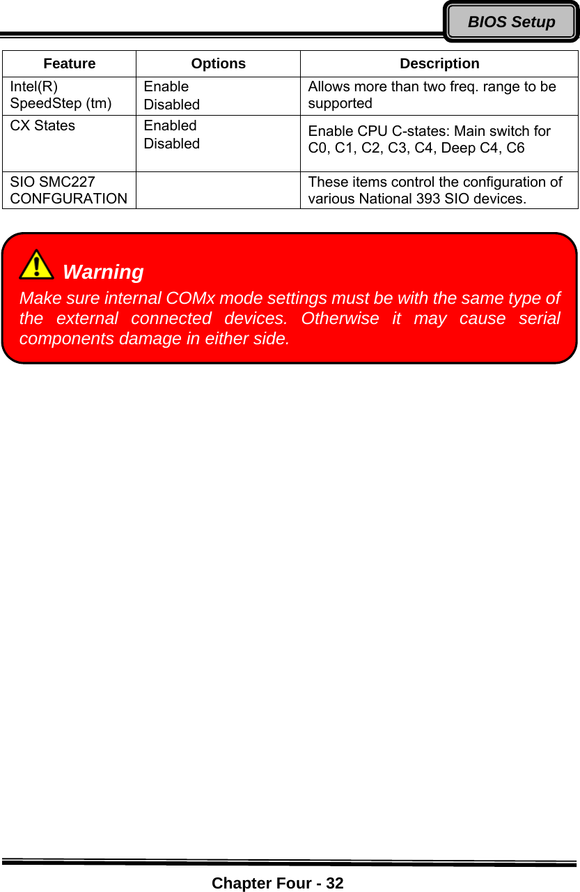
![Chapter Four - 30BIOS Setup Advanced Menu Phoenix SecureCore (tm) Setup Utility Main Advanced Security Boot Exit Item Specific Help Boot-time Diagnostic Screen: [Enabled] QuickBoot Mode: [Enabled] IGD - Boot Type: [VBT Default] PS/2 Mouse [Auto Detect] PCI Express Port #1 [Enabled] Device 29 USB 2.0 Enable: [Enabled] Passive Cooling Trip Point: [87 C] Core Multi-Processing: [Enabled] Intel(R) SpeedStep (tm) [Enabled] CX States [Enabled] PCI Hot-Plug Resources [Enabled] ► SIO SMC227 CONFIGURATION Display the diagnostic screen during boot F1 Help ↑↓ Select Item –/+ Change Values F9 Setup Defaults Esc Exit ↔ Menu Enter Select ► Sub-Menu F10 Save and Exit Warning Incorrect settings may cause system malfunction. To correct it, restore the Setup Default with <F9>.](https://usermanual.wiki/MilDef-Crete/RT9/User-Guide-1316477-Page-40.png)
![Chapter Four - 33BIOS Setup SIO SMC27 CONFIGURATION Sub-Menu Phoenix SecureCore (tm) Setup Utility Advanced SIO SMC227 CONFIGURATION Item Specific Help COM1 port: [3F8-IRQ 4] COM1 mode: [COM1] COM2 port: [2F8-IRQ 3] COM2 mode: [COM2] COM3 port: [3E8-IRQ 10] COM3 mode: [COM3] COM4 port: [2E8-IRQ 5] COM4 mode: [COM4] Printer1: [378-IRQ 3] Printer1 mode: [Standard] Printer2: [Disabled] Configure COM1 using device options: [Disabled] No configuration [3F8-IRQ 4] Set the base I/O address for COM1 F1 Help ↑↓ Select Item –/+ Change Values F9 Setup Defaults Esc Exit ↔ Menu Enter Select ► Sub-Menu F10 Save and Exit SIO SMC27 CONFIGURATION Sub-Menu Selections You can make the following selections on the SIO SMC27 CONFIGURATION Sub-Menu. Feature Options Description COM1 port 3F8-IRQ 4 Disabled Configure COM1 using device options: [Disabled] No configuration [3F8-IRQ 4] Set the base I/O address for COM1 COM1 mode COM1 TTL1 Configure UART mode options: [COM1]: External Device [TTL1]: Internal Device COM2 port 2F8-IRQ 3 Disabled Configure COM2 using device options: [Disabled] No configuration [2F8-IRQ 3] Set the base I/O address for COM2 COM2 mode COM2 Configure UART mode options:](https://usermanual.wiki/MilDef-Crete/RT9/User-Guide-1316477-Page-43.png)
![Chapter Four - 34BIOS SetupFeature Options Description TTL2 [COM2]: External Device [TTL2]: Internal Device COM3 port 3E8-IRQ 10 Disabled Configure COM3 using device options: [Disabled] No configuration [3E8-IRQ 10] Set the base I/O address for COM3 COM3 mode COM3 TTL3 Configure UART mode options: [COM3]: External Device [TTL3]: Internal Device COM4 port 2E8-IRQ 5 Disabled Configure COM4 using device options: [Disabled] No configuration [2E8-IRQ 5] Set the base I/O address for COM4 COM4 mode COM4 TTL4 Configure UART mode options: [COM4]: External Device [TTL4]: Internal Device Printer1 378-IRQ 7 Disabled Configure Printer1 device options: [Disabled] No configuration [378-IRQ 7] Set the base I/O address for Printer1 Printer1 mode Standard ECP EPP Configure Printer1 mode options: Standard EPP ECP Printer2 Disabled 3BC Configure Printer2 device options: [Disabled] No configuration [3BC] Set the base I/O address for Printer2](https://usermanual.wiki/MilDef-Crete/RT9/User-Guide-1316477-Page-44.png)
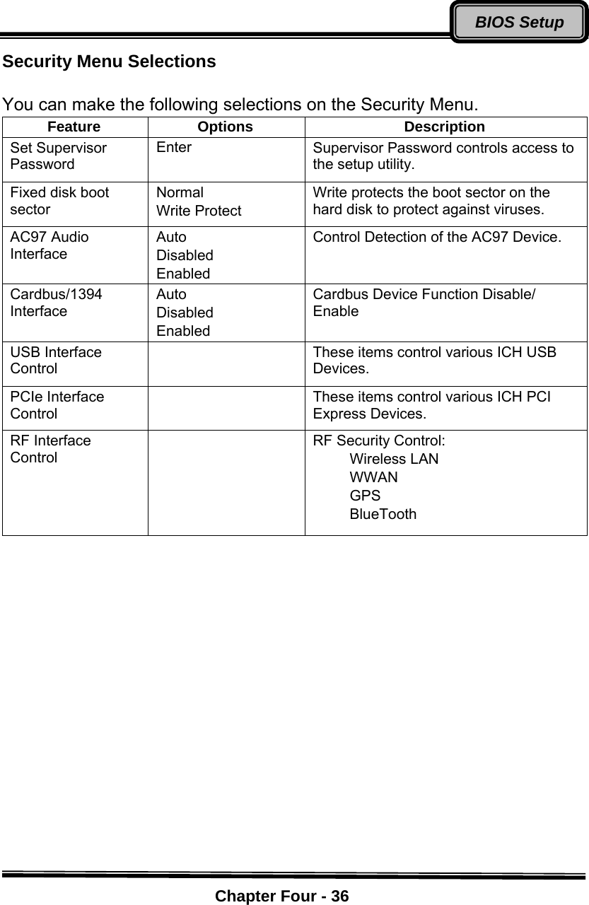
![Chapter Four - 35BIOS Setup Security Menu Phoenix SecureCore (tm) Setup Utility Main Advanced Security Boot Exit Item Specific Help Supervisor Password Is: Clear User Password Is: Clear Set Supervisor Password [Enter] Set User Password [Enter] Diskette access: [Supervisor] Fixed disk boot sector: [Normal] Password on boot: [Disabled] AC97 Audio Interface: [Auto] Cardbus/1394 Interface [Auto] ►RF Interface Control Supervisor Password controls access to the setup utility. F1 Help ↑↓ Select Item –/+ Change Values F9 Setup Defaults Esc Exit ↔ Menu Enter Select ► Sub-Menu F10 Save and Exit Warning If you forget user/supervisor password, the computer has to send back to manufacturer and replace Flash ROM to make it work again. Note: ¾ Once you enter the incorrect password for three times, “System Disabled” will show on the screen. Please press the power switch for more than 5 seconds to shut down the computer. After shutting down, you are able to restart the system to enter the password again,](https://usermanual.wiki/MilDef-Crete/RT9/User-Guide-1316477-Page-45.png)
![Chapter Four - 37BIOS Setup RF Interface Control Sub-Menu Phoenix SecureCore (tm) Setup Utility Security RF Interface Control Item Specific Help Wireless LAN: [Disabled] WWAN: [Disabled] GPS: [Disabled] BlueTooth: [Disabled] Wireless LAN Control F1 Help ↑↓ Select Item –/+ Change Values F9 Setup Defaults Esc Exit ↔ Menu Enter Select ► Sub-Menu F10 Save and Exit RF Interface Control Sub-Menu Selections You can make the following selections on the RF Interface Control Sub-Menu. Feature Options Description Wireless LAN Enabled Disabled Wireless LAN Control WWAN Enabled Disabled WWAN Control GPS Enabled Disabled GPS Control BlueTooth Enabled Disabled BlueTooth Control](https://usermanual.wiki/MilDef-Crete/RT9/User-Guide-1316477-Page-47.png)