Mini Mitter XTP1 Integrated Physiological Monitoring System User Manual Tinman Book
Mini Mitter Co. Inc. Integrated Physiological Monitoring System Tinman Book
Contents
- 1. Users Manual
- 2. Users Manual part 1
- 3. Users Manual part 2
Users Manual part 1

Mini Mitter Company, Inc.
Bend, OR USA
VitalSense
®
Integrated Physiological Monitoring System
Instruction Manual
Version 1.1
This document is Mini Mitter Part Number 910-0500-XX
© 2003-2004 Mini Mitter Company, Inc.
VitalSense
®
is a registered trademark of Mini Mitter Company, Inc.
Medic Mode
™
is a trademark of the Mini Mitter Company, Inc.
Preliminary
(
includes Tinman)
MINI MITTER COMPANY, INC.
WARRANTY POLICY
1. WARRANTY: Mini Mitter warrants that upon delivery the goods sold hereunder will be free of defects in materials and workmanship, and
such goods will substantially conform to the specifications furnished by the Seller, and to any drawings or specifications furnished to the
Buyer by Mini Mitter if approved by Mini Mitter.
a) Commencement of Warranty – The warranty period begins on the date of delivery.
b) Duration of Warranty – The goods sold hereunder are warranted for a period of twelve months, except PDT-4000 and PDT-4000HR, which
are warranted for two years.
c) Third Party Product Warranty – Third party products purchased by Buyer through Mini Mitter are covered by the manufacturer’s warranty
and ARE NOT COVERED BY THE MINI MITTER WARRANTY.
d) Place of Repair or Replacement. Buyer must return the defective or nonconforming goods upon request to Mini Mitter at 20300 Empire Ave-
nue, Building B-3; Bend, OR 97701, not later than 15 days after Mini Mitter’s receipt of notice of the alleged defect or nonconformance.
Buyer shall prepay transportation charges. Mini Mitter shall pay for the return of the goods to Buyer. No goods are to be returned to Mini
Mitter without prior authorization and a valid Corrective Action Request (CAR) number.
e) Limitation of Warranty The foregoing warranty shall not apply to defects resulting from (a) improper or inadequate maintenance by Buyer;
(b) unauthorized modification of the goods; (c) operation of the goods outside of the environmental specifications for the goods; (d) neglect,
misuse or abuse of the goods or (e) modification or integration with other goods not covered by a Mini Mitter warranty when such modifica-
tion or integration increases the likelihood of damage to the goods.
f) Technical assistance – The warranty set forth above shall not be enlarged, diminished or affected by and no obligation or liability shall arise
from Mini Mitter’s rendering of technical advice, assistance or services in connection with Buyer’s order of the goods furnished hereunder.
The Buyer is not relying on Mini Mitter's skill or judgment to select or furnish suitable goods.
THE WARRANTY SET FORTH ABOVE IS EXCLUSIVE AND MINI MITTER GIVES NO OTHER WARRANTY WRITTEN OR
VERBAL, EXPRESS OR IMPLIED. MINI MITTER SPECIFICALLY DISCLAIMS THE IMPLIED WARRANTIES OF MERCHANT-
ABILITY AND FITNESS FOR A PARTICULAR PURPOSE. MINI MITTER’S STANDARD WARRANTY POLICY COVERING
ANY MINI MITTER PRODUCTS SHALL BE NULL, VOID, AND OF NO EFFECT IF THE BUYER OR ANY THIRD PARTY USES
THAT PRODUCT FOR ANY USE OTHER THAN THE INTENDED USE OF THAT PRODUCT.
2. LIMITATION OF REMEDIES AND LIABILITY. The remedies provided herein are Buyer’s sole and exclusive remedies. Mini Mitter shall
have no responsibility other than, at Mini Mitter’s option, to repair or replace defective or nonconforming goods or to refund the purchase
price of defective or nonconforming goods in the event of breach of any warranty. IN NO EVENT SHALL Mini Mitter BE LIABLE FOR
ANY DIRECT, INDIRECT SPECIAL, INCIDENTAL OR CONSEQUENTIAL DAMAGES (INCLUDING LOSS OF PROFITS)
WHETHER BASED ON CONTRACT, TORT OR ANY OTHER LEGAL THEORY. In the event that any limitation of warranty or dis-
claimer of liability is found to be unlawful or inapplicable, or to have failed of its essential purpose, Mini Mitter’s liability shall be limited to
the amount paid by the Buyer for the specific goods that caused such liability.
900-0016-01

iii
Technical Support v
Notices to Practitioners and Subjects vi
System Introduction 1-1
Monitor Operation/Sensor Activation 2-1
VitalSense Application Program 3-1
Maintenance 4-1
VitalSense XHR Heart Rate Sensor 5-1
Appendices
Frequently Asked Questions A-1
Universal Coordinated Time B-1
Medic Mode
™
C-1
Specification D-1
Index
Table of Contents
iv

v
Thank You! .....for purchasing Mini Mitter products. If you need assistance with your
VitalSense Physiological Monitoring System, remember Mini Mitter
support continues after the purchase. If you have any problems or
questions, please call our Technical Support staff of technicians,
engineers, and scientists. We are available by telephone, fax, e-mail, or
website.
Contacting Mini Mitter Technical Support
Mailing and
Shipping
Address
Mini Mitter Company, Inc.
20300 Empire Avenue, Building B-3
Bend, OR 97701 USA
Telephone (800) 685-2999
(541) 322-7272
Fax (541) 322-7277
E-Mail mm@minimitter.com
Website www.minimitter.com
vi
Safety Labels and Terminology
DANGER indicates an imminently hazardous situation which, if not
avoided, will result in death or serious injury.
WARNING indicates a potentially hazardous situation which, if not
avoided, could result in death or serious injury.
CAUTION (with safety alert symbol) indicates a potentially hazard-
ous situation which, if not avoided, may result in minor or moderate
injury.
CAUTION without safety alert symbol indicates a potentially haz-
ardous situation which, if not avoided, may result in property dam-
age, including equipment and/or data.
If found on a device, this symbol means that there is additional
information in the manual that must be read. This symbol is typically used
when there is not enough room for text.
NOTE:
A “Note” between two lines is an explanatory statement to aid the
practitioner or subject.
vii
Notices to Practitioners and Subjects
Electromagnetic Interference (EMI) Advisories
Introduction
The VitalSense Integrated Physiological Monitoring System uses wireless
telemetry to send data over a distance. By nature, wireless devices use an
“open” channel which is shared by other wireless devices which may be
interfered with, or may interfere with the VitalSense system.
Consequently, the customer is advised to carefully consider the
environment in which the VitalSense system will be used. The VitalSense
system was designed for use in general health care and household
environments. It may also be used in research facilities and field research.
The VitalSense system can be used in some military environments, but is
not intended for use in military aircraft or shipboard.
VitalSense sensors should not be ingested or affixed during Mag-
netic Resonance Imaging (MRI). Sensors contain ferro-magnetic
materials.
VitalSense Frequency
The channel frequency for the VitalSense system is 40.68 MHz and the
frequency band is 40.66 – 40.70 MHz. Although this is a seldom-used
band, Mini Mitter recommends that you check the channel frequency of
other wireless devices intended for use in the vicinity of the VitalSense
system. Other wireless devices operating in the frequency band of 40.66 –
40.70 MHz may interfere with, or may be interfered by the VitalSense
system. Generally, the output power of the sensors is extremely low and is
unlikely to interfere with any equipment in the area. It is more likely that
another device operating in the same band will interfere with the
VitalSense system.
EMI Effects on VitalSense System
If the VitalSense system experiences interference, the monitor will no
longer receive intelligible transmissions from the sensors. In Standard
Mode, whenever transmissions from the sensor are missed, an asterisk is
displayed next to the temperature. This asterisk remains until a
transmission is received. The data is updated on average every 15 seconds.
If the display flashes, but the asterisk remains, the sensors are still
experiencing interference. In Medic Mode™, data from a particular sensor
experiencing interference will not be displayed at all. Once the interfering
signal is eliminated, the asterisk displayed in Standard Mode will
disappear, and new data will be displayed in either mode.

viii
EMI Avoidance
The VitalSense system is intended as a short range wireless device. The
maximum distance at which the capsule sensor can be used is 1 m, and the
maximum distance at which the patch can be used is 2 m. If transmissions
appear to be lost, bring the monitor closer to the sensors. Move the system
away from any devices you suspect may be emitting electrical radiation.
The VitalSense system is intended to be an ambulatory system worn on
the body, with the monitor placed at or near the waist. Because of its low
power, it is not recommended for use in electrically noisy environments.
Although protected by filtering, the VitalSense system is susceptible to
frequencies other than the channel band. The VitalSense system has been
tested for RF immunity between 2 MHz and 1800 MHz. Generally, the
system can still be used when the maximum field strength of the
interfering signal is 10 V/m. Table 1.1 lists those frequencies which may
cause interference at levels below 10 V/m.
Table 1.1
Frequencies where RF Immunity is less than 10 V/m
Frequency Dermal Patch RF
Immunity Level Capsule RF
Immunity Level
17 MHz - 26 MHz 7 V/m 3 V/m
56 MHz - 83 MHz 5 V/m 3 V/m
678 MHz -782 MHz 5 V/m 3 V/m

ix
Radio Frequency Environments
Table 1.2 summarizes the general electromagnetic environments and lists
the environments in which the system has been verified to operate. For
additional information, contact Mini Mitter Company, Inc.
Operation within environments other than those verified may cause loss of
data. Mini Mitter Company, Inc. is not responsible for customer operation
of the system within environments other than those verified.
Note1 - Verified in accordance with 47 CFR Part 15.229
Note2 - Verified in accordance with IEC60601-1-2 and tested in accordance with
MIL-STD 461E and MIL-STD 462E, Test CS114, and RS103
Note3 - Tested in accordance with MIL-STD 461E and MIL-STD 462E, RE102
Note4 - Tested in accordance with MIL-STD 461E and MIL-STD 462E, CS114
and RS103
Note5 - Metal detectors may be activated by the VitalSense monitor. Anti-theft
security systems (such as found in retail stores and libraries) may be activated by
the VitalSense system.
Common Radio and Television Frequencies
Table 1.2
General Electromagnetic Environments
Environment Emissions Susceptibility
General Research Verified (Note1)Verified (Note2)
Clinical-Hospital Verified (Note1)Verified (Note2)
Ambulatory Verified (Note1)Verified (Note2 and
Note5)
Battlefield Limited (Note3)Verified (Note4)
Helicopter Not verified Not verified
Ambulance Not verified Not verified
Shipboard Not verified Not verified
Aircraft Not verified Not verified
Although they may vary somewhat worldwide, the following are
commonly used frequencies in North America.
Table 1.3
Commonly Used Frequencies
Transmission
Type Frequency Range
AM Radio 535 kHz to 1605 kHz
FM Radio 88 MHz to 108 MHz
CB Radio 26.965 MHz to 27.405 MHz
VHF Television 55.25 MHz to 83.25 MHz
175.25 MHz to 211.15 MHz
UHF Television 471.25 MHz to 801.25 MHz
x
Medical Telemetry Systems
VitalSense has been designed in accordance with the FDA advisory,
“FDA Public Health Advisory: Risk of Electromagnetic Interference with
Medical Telemetry Systems,” July 10, 2000; and in accordance with FDA
Guidance Document, “Wireless Medical Telemetry Risks and
Recommendations.” In regard to those advisories:
•The VitalSense system does not operate in the TV or PLMRS bands
at 174-216 MHz and 450-470 MHz.
•VitalSense does not operate within the frequency bands 26.96-27.28
MHz, utilized by remote control devices.
Electrostatic Discharge Effects on Monitor
The VitalSense Monitor is designed to recover from air discharge
Electrostatic Discharge (ESD) effects of 12 kV or less to any surface of
the monitor. If an ESD discharge of greater than 12 kV is directly applied
to the monitor, it may result in the monitor display momentarily going
blank. If this occurs, the VitalSense Monitor will refresh the monitor
display either when any button is pressed, or if a sensor transmission is
received.

xi
Precautions Prior to Using the VitalSense System
Restrictions Federal law restricts the VitalSense Physiological Monitoring System
products for sale to or on the order of a health care practitioner licensed by
the law of the State in which he/she practices to use or order the use of this
device.
Emissions
This equipment has been tested and found to comply with the limits for a
Class B digital device, pursuant to part 15 of the FCC Rules. These limits
are designed to provide reasonable protection against harmful interference
in a residential installation. This equipment generates, uses and can radiate
radio frequency energy and, if not installed and used in accordance with
the instructions, may cause harmful interference to radio communications.
However, there is no guarantee that interference will not occur in a
particular installation. If this equipment has been installed improperly and
as a consequence does cause harmful interference to radio or television
reception, this can be determined by turning the equipment off and on.
The user is encouraged to try to correct the interference by one or more of
the following measures:
•Reorient or relocate the receiving antenna.
•Increase the separation between the equipment and receiver.
•Consult the dealer or an experienced radio/TV technician for
assistance.
Interference
This device complies with part 15 of the FCC Rules. Operation is subject
to the following two conditions:
•This device may not cause harmful interference.
•This device must accept any interference received, including
interferences that may cause undesired operation.
•Also see “Electromagnetic Interference (EMI) Advisories” on
page-vii.

xii
Travel by Commercial Aircraft
Following activation, VitalSense sensors are radio transmitters. The
Dermal Patch sensor has a range up to 2 meters, and the Capsule Sensor
has a range up to 1 meter. The VitalSense Monitor can be a source of radio
interference. They should not be used on commercial aircraft without the
expressed permission of the governing aircraft security agency in
countries of travel and the airline carrier. In the United States, this is the
Transportation Security Administration under the Office of Homeland
Security. Mini Mitter suggests the following:
•Do not activate the sensors until your flight has concluded.
•If you do inadvertently find yourself in the position of having to board
an aircraft with activated sensors, realize you may have to do the
following:
Remove all Dermal Patch Sensors and leave them behind.
Turn off the VitalSense Monitor. If it is in Lockout Mode, remove
the battery. The monitor will retain the data that has been collected.
If you have ingested a Capsule Sensor, it is recommended that you
tell the security screener that you are wearing an ingested medical
device.
It is recommended that you be totally honest with airport security
personnel. Although they are familiar with implanted devices, wireless
thermometers may be unfamiliar to them. Policies regarding medical
devices are typically very accommodating. If there are any questions we
can help answer, please call us. See “Contacting Mini Mitter Technical
Support” on page-v.
Modification of VitalSense Devices
Any changes to the VitalSense Physiological Monitoring System not
expressly approved by Mini Mitter will void the practitioner’s or
subject’s authority to operate the devices or the software.
NOTE: VitalSense conforms to all of the requirements established
in ASTM-E1112-00, Standard Specification for Electronic Ther-
mometer for Intermittent Determination of Patient Temperature,
clauses 4.1 and 4.2.

xiii
Sanitizing VitalSense Components
The VitalSense monitor may be sanitized with a soft cloth moistened with
a non-alcohol based antibacterial cleaner.
The Capsule Sensor and Dermal Patch Sensor are single-use disposable
devices. They are supplied ready-for-use as long as they remain in their
original factory packaging.
For VitalSense Monitor maintenance cleaning, see “Cleaning” on
page4-6.
Do not autoclave the VitalSense monitor or the associated sensors.
They will be destroyed in the process. Only gas processes may be
used.

xiv
Precautions Prior to Using the VitalSense Monitor
Safety
This device is classified as having Type CF protection against electrical
shocks during the sensor activation procedure.
NOTE: For additional advisories with respect to the VitalSense
Monitor, see “Precautions Prior to Using the VitalSense System”
on page-xi, and “EMI Effects on VitalSense System” on page-vii.
♥

xv
Precautions Prior to Using the Dermal Patch Sensor
Read before administering Dermal Patch Sensor!
Description
•Supplied one Dermal Patch Sensor per package
•Patch is biocompatible, colored plastic
•Temperature Sensing Range: -20 °C to 60 °C
•Reception Range: maximum of 2 meters
•Battery life following activation: maximum of 240 hours (10 days)
Indications
An indication is a sign or circumstance that indicates proper treatment.
•The VitalSense Dermal Patch is a wireless, miniaturized, externally
activated, dermally affixed, biocompatible thermometer.
•The Dermal Patch Sensor is to be used for monitoring vital signs
(external skin temperature) as part of a complete physiological sensor
and monitoring system.
•The subject is not restricted to a medical environment. The subject may
shower and participate in normal activities while the Dermal Patch is in
place.
•The Dermal Patch is a single-use sensor.
Contraindications
A contraindication is any circumstance that indicates a form of treatment
may be inappropriate.
This device is contraindicated if the patient presents or has a history of any
of the following conditions:
•This product should not be used if the patient has known skin allergies,
a break in the skin at the application site, or other abnormal skin
conditions. If a skin rash occurs, notify the health care practitioner
immediately.
Warnings
A warning indicates a condition that may endanger the subject.
•DO NOT attempt an MRI (magnetic resonance imaging) if a Dermal
Patch has been affixed. Remove the device prior to MRI.
Affix an MRI Warning wrist band (supplied) to the subject with
instructions to wear it until the Dermal Patch has been removed.
•DO NOT affix Dermal Patch if any damage is visible to the packaging
or the device.
•Keep sensors away from small children. They can be a choking hazard.

xvi
Cautions
The following cautions indicate conditions that may result in minor or
moderate injury to the subject.
•The Dermal Patch Sensor should be administered only by a health care
practitioner.
•Following activation, the Dermal Patch Sensor can be affixed to nearly
any flat, hairless area on the body. Placement, however, is limited to the
size of the patch. It cannot be trimmed or altered, and should not be
bent or crushed. It would, for example, be appropriate for a large
muscle of the arm or leg, or axilla, but not on the bottom of the foot or
around a bony structure such as the side of the wrist.
The following cautions indicate possible damage to the equipment, or
erroneous or incomplete data.
•Data points could be missed if you are close to radio or television
transmission sites, or other sources of electrical signals. See “EMI
Avoidance” on page-viii of this section.
•DO NOT administer a Dermal Patch Sensor after the expiration date.
•The Dermal Patch Sensor should be administered every 3 to 4 days,
when the Patch looses contact with the skin, or as directed by a health
care practitioner.
•Avoid the use of lotions and emollients in the area of the Dermal Patch
Sensor. Their use may cause the patch adhesive to loosen.
•DO NOT leave the monitor out of range of the Dermal Patch Sensor for
more than 30 minutes.
Adverse Reactions
May cause skin rash. Remove hair and clean skin before activation and
application of Patch. If discomfort occurs or rash appears, discontinue use
and notify health care practitioner.

xvii
Precautions Prior to Using the Capsule Sensor
Read before administering capsule!
Limitations of Capsule Sensor
The VitalSense ingestible capsule thermometer is a Class II Medical
Device according to 21 CFR 882.1845 and is classified as a Surface
Contacting Device according to ISO 10993-1. The capsule is intended to
be used in contact with the mucosal membrane (alimentary tract) only.
The VitalSense ingestible capsule thermometer must not be used in any
situation where the mucosal membrane is already breached by surgery or
trauma. The VitalSense ingestible capsule thermometer is not intended to
be used as an implant. For additional information, contact Mini Mitter
Company, Inc. See “Contacting Mini Mitter Technical Support” on
page-v.
Description
•Supplied as one Capsule Sensor per package
•Sensor is colored biocompatible polycarbonate
•Temperature Sensing Range: 25 °C to 50 °C
•Reception Range: Maximum of 1 meter
•Battery life following activation: maximum of 240 hours (10 days)
Indications
An indication is a sign or circumstance that indicates proper treatment.
•The VitalSense Capsule Sensor is a wireless, miniaturized, externally
activated, ingestible, biocompatible thermometer.
•It is to be used for monitoring vital signs (core body temperature) as
part of a complete physiological sensor and monitoring system.
•Once ingested, the patient is not restricted to a medical environment.
•The Capsule Sensor may be taken without regard to dietary restrictions.
•It is a single-use sensor.
Contraindications
A contraindication is any circumstance that indicates a form of treatment
may be inappropriate.
This device is contraindicated if the patient presents or has a history of any
of the following conditions:
•Abnormalities in swallowing
•Esophageal or bowel strictures
•Fistulas
•Gastrointestinal obstructions

xviii
If suspected, a contrasted X-ray series should be considered prior to
ingestion.
Warnings
A warning indicates a condition that may endanger the subject or patient.
•DO NOT attempt an MRI (magnetic resonance imaging) if a Capsule
Sensor has been ingested. Wait until the device is passed from the
digestive system.
Affix an MRI Warning wrist band (supplied) to the subject with
instructions to wear it until the Capsule Sensor has been passed.
•DO NOT ingest if any damage is visible to the packaging or the device.
•DO NOT chew prior to swallowing. The electronics within the device
will be made inoperable.
•The Capsule Sensor should be swallowed with water or other suitable
liquid.
•DO NOT administer a Capsule Sensor after the expiration date.
•If gastrointestinal discomfort occurs following ingestion, report it to the
health care practitioner. Nausea, vomiting, or pain should be reported
immediately.
•Keep Capsule Sensors away from small children. They can be a
choking hazard.
•The Capsule Sensor is not to be implanted.
Cautions
The following cautions indicate possible damage to the equipment, or
erroneous or incomplete data.
•DO NOT open the VitalSense Capsule Sensor protective packaging
until ready for use.
•The Capsule Sensor should be administered only by a health care
practitioner.
•
The following cautions indicate possible damage to the equipment, or
provide erroneous or incomplete data.
•Data points could be missed if you are close to radio or television
transmission sites, or other sources of electrical signals. See “EMI
Avoidance” on page-viii of this section.
•DO NOT administer a Capsule Sensor after the expiration date.
•DO NOT leave the monitor out of range of the Capsule Sensor for more
than 30 minutes.
•The VitalSense Monitor battery level should be checked prior to use.
xix
Adverse Reactions
•May cause choking. Should be taken with water.
•In rare instances, may become lodged in the intestines.

xx
Precautions Prior to Using VS-XHR Heart Rate
Sensor
Read before administering VS-XHR Heart Rate Sensor!
Description
VS-XHR is a cardiac monitor sensor, used to detect, measure, and
transmit Heart Rate and Respiration Rate values to the VitalSense
Integrated Physiological Monitoring System (VS-IPMS). VS-XHR
attaches directly to the chest surface using standard disposable ECG
(EKG) electrodes. VS-XHR is powered from its own internal rechargeable
lithium coin cell; there is no external power source. There are no ECG
leads. VS-XHR is not equipped with any alarm function.
Intended Use
VS-XHR Sensor is intended to be used as an HR and/or RR monitor, in
conjunction with the VS-IPMS. VS-XHR is not equipped with alarms to
signal tachycardia or any other cardiac arrhythmias.
Indications
An indication is a sign or circumstance that indicates proper treatment.
•VS-XHR Sensor is an ambulatory, wireless, chest-worn, dermally
affixed, Heart Rate and Respiration Rate Sensor.
•The VS-XHR Sensor is to be used for monitoring vital signs (heart rate
and respiration rate) as part of a complete physiological sensor and
monitoring system.
•The subject is not restricted to a medical environment. The subject may
participate in normal activities while the VS-XHR Sensor is in place.
•The VS-XHR Sensor is a multi-use sensor.
•VS-XHR, in combination with VitalSense Physiological Monitoring
System, may be used where quantifiable measurement of human Heart
Rate and/or Respiration Rate are needed.

xxi
Contraindications
A contraindication is any circumstance that indicates a form of treatment
may be inappropriate.
•The VS-XHR Sensor is contraindicated for the detection of Heart Rate
due to bigeminal arrhythmias or systoleic arrhythmias.
•The VS-XHR Sensor is contraindicated for use in conjunction with
pacemakers, electrosurgical equipment, and defibrillators.
•VS-XHR Sensor is contraindicated for use in measuring ST segment
shifts.
•VS-XHR Sensor is contraindicated for use in measuring ventricular
ectopic beats, ventricular flutter or fibrillation; or supraventricular
ectopic beats, atrial flutter, or fibrillation.
•VS-XHR Sensor is contraindicated for use with neonatal or infant
subjects whose body mass is 10 kg or less.
•VS-XHR Sensor is contraindicated for patients with current or known
history of dermal allergies, dermal sensitivity to ECG electrodes, or
dermal lesions. Consult ECG electrode manufacturer’s directions for
appropriate ECG electrode type and usage. Discontinue use if dermal
irritation or allergic reaction to ECG electrode occurs.
Warnings
A warning indicates a condition that may endanger the subject.
Pacemaker Patients - This device does not reject pacemaker pulses.
Rate meters may continue to count the pacemaker rate during occurrences
of cardiac arrest or some arrhythmias. Do not rely entirely upon rate
meters to measure heart rate for pacemaker patients. Keep pacemaker
patients under close surveillance.
Magnetic Resonance Imaging (MRI)
DO NOT attempt an MRI (magnetic resonance imaging) if a VS-XHR
Sensor has been affixed. Remove the device prior to MRI.
Affix an MRI Warning wrist band (supplied) to the subject with
instructions to wear it until the VS-XHR Sensor has been removed.
Cardiac Arrhythmias
This devices does not provide alarms that signal the onset or presence of
cardiac arrhythmias, including tachycardia.
Electrosurgical Equipment
Electrosurgery or electrocautery equipment may interfere with or damage
this device. Do not rely on this device to measure heart rate or respiration
rate when electrosurgery equipment is being used.

xxii
Defibrillation
Defibrillator use may interfere with or damage this device. Do not rely on
this device to measure heart rate or respiration rate during defibrillator
use. Remove VS-XHR prior to defibrillator use.
Cautions
The following cautions indicate conditions that may result in minor or
moderate injury to the subject.
Infant Use
VitalSense-XHR Heart Rate Sensor is not intended for use on infants
weighing less than 10 kg.
ST Segment Shifts
This equipment is not designed to measure ST segment shifts.
The following cautions indicate possible damage to the equipment, or
erroneous or incomplete data.
•Data points could be missed if you are close to radio or television
transmission sites, or other sources of electrical signals. See “EMI
Avoidance” on page-viii of this section.
•Avoid the use of lotions and emollients in the area of the XHR Heart
Rate Sensor electrodes. Their use may cause the adhesive to loosen.
•DO NOT leave the monitor out of range of the XHR Heart Rate Sensor
for more than 30 minutes.
Electrial Shock Protection
This device provides degree of protection against electric shock as Type B
applied part per IEC 60601-1, clause 6.1(l).
Adverse Reactions
Electrodes may cause skin rash. Remove hair and clean skin before
activation and application of Patch. If discomfort occurs or rash appears,
discontinue use and notify health care practitioner.

xxiii
Precautions Prior to Using the Multicharger
Read before charging VS-XHR Heart Rate Sensor!
Description
The purpose of the Multicharger is to charge multiple VS-XHR Heart
Rate Sensors. An AC to DC converter is provided which powers the
device. Up to three VS-XHR Sensors can be mounted on the
Multicharger, providing a full charge within 11 hours (typical).
Cautions
The DC plug on the Multicharger power supply, or the AC power cord on
the power supply, both serve as the cutoff switch for power to the
Multicharger. Ensure that the socket-outlet providing voltage to the power
supply is located nearby and is readily accessible.
Always use the supplied AC power cord with the Multicharger. Do not
substitute power cords other than the one supplied with the Multicharger.
xxiv
1-1
SECTION
1
C
HAPTER
1
V
ITAL
S
ENSE
S
YSTEM
I
NTRODUCTION
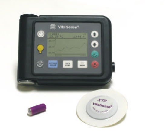
This is an instruction manual for the operation and maintenance of the
VitalSense Integrated Physiological Monitoring System. This wireless
system consists of the following components:
VitalSense
Components •VitalSense Monitor
•Dermal Patch Sensor
•Capsule Sensor
•VitalSense Application Software
•Serial monitor-to-PC interface cable
Once a sensor is activated, it measures and reports the temperature data to
the monitor an average of four times per minute. The temperature data are
time-stamped and recorded in the non-volatile memory.
1-2 Introduction
A Standard Mode VitalSense Monitor can monitor up to ten sensors. In
order to do this, each sensor must be activated by the monitor that will be
recording that specific sensor. During activation, each sensor and the
monitor are synchronized.
In optional Medic Mode™, an unlimited number of sensors may be
operationally verified and the temperature recorded with a time stamp.
Getting Started - THIS MUST HAPPEN FIRST
The following must occur before a new data collection session can
begin:
•Monitor clock must be set - (from monitor front panel or the host PC)
•Erase data memory - (from monitor front panel or the host PC)
•Logging must be turned on - (from monitor front panel or the host PC)
•Sensor(s) must be activated - (from the monitor only)
See “ Monitor Setup for Data Collection ” on page2-4.
Monitor
The VitalSense Monitor is a central element in the VitalSense system. It
serves to activate the sensors, track and record data from the sensors, and
provide an interface to a computer.
Sensor activation is a key event in the operation of VitalSense. It is used to
synchronize the monitor with each sensor. Once activated, the monitor can
display the incoming data in real-time and at the same time log the data to
the non-volatile memory for future transfer to a computer.
Sensors
VitalSense sensors are activated by the VitalSense Monitor. Once
activated, a sensor will begin its monitoring assignment, and will continue
to function until the battery expires (approximately 240 hours), the sensor
is removed from the sensor schedule, or the sensor is disposed.
Each sensor is given an identity number at the factory, along with
temperature calibration data. During activation, these data are
automatically retrieved from the sensor and stored in the monitor memory.
All sensors are activated using essentially the same process:
•A specific optical signal from the monitor activates the sensor.
•By radio, the sensor transfers its identification and calibration data to
the monitor.
Following activation, the sensor is either swallowed (Capsule Sensor), or
affixed to the body (Dermal Patch Sensor). The activation process is
identical for each sensor. Sensors are single-use and cannot be de-
activated. Additional sensors may be ordered from Mini Mitter Company,
Inc. See “ Contacting Mini Mitter Technical Support ” on page-v.
1-3
Tracking
Tracking is a term used in this manual which refers to the synchronization
of the VitalSense Monitor and the sensors.
In order to preserve battery power of the VitalSense Monitor and conserve
the power of the sensors, the sensors are designed to transmit according to
a pre-determined schedule. Both the sensor and the monitor which
activated it have this schedule. As a result, the monitor only “listens” for a
specific sensor for a short period during the expected transmission time. It
is through the activation process and the periodic reception of these
transmissions that the monitor remains synchronized with the sensor
transmission schedule. The monitor quite literally “tracks” the minor
variations between the two clock sources at each transmission.
Firmware
VitalSense firmware is operational information that is programmed into
the VitalSense Monitor non-volatile memory. When calling Mini Mitter
Technical Support, the version number of this firmware can be very
helpful. To find the firmware version using the VitalSense Application
Program, see “ Firmware Version ” on page3-21.
Software
Installed, the VitalSense Application Software converts a PC to “host
status” for the VitalSense Application Program, allowing setup of select
monitor functions, real-time monitoring of data, and retrieval of data
which have been stored on the monitor.
Installation of the VitalSense Application Software can be found under
“ Installation of Software ” on page3-3.
Calibration
VitalSense transmitter/sensors do not require calibration prior to use.
EMI and ESD Susceptibility
It is recommended you read the advisories concerning EMI and ESD.
They begin on page-vii.
1-4 Introduction
2-1
SECTION
2
C
HAPTER
2
V
ITAL
S
ENSE
M
ONITOR
O
PERATION
VitalSense Monitor - Description
The VitalSense Monitor is a splash-resistant, battery-operated receiver
and logger. It activates the sensor via an optical beam, receives data from
the sensor by radio, records data in a non-volatile memory, and facilitates
transferring the data to a computer via a cable.
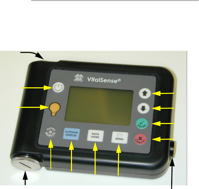
Monitor Front Panel
Power
Activate
Sensor
Data
Views Menu
Up
Down
Enter
Cancel
Backlight
Marker
Button
Battery compartment
RS-232 port
(not shown)
Activation
Port

2-2 Monitor Operation and Sensor Activation
Front Panel Controls
VitalSense controls are sealed, splash-resistant, and provide tactile
feedback.
Power On/Off
Turns the monitor on and off. Data and settings are preserved when the power is
turned off.
Backlight
Light is activated for approximately 10 seconds when this button is pressed. If
subsequent buttons are pressed, the backlight will remain on.
Marker Button
Inserts a time mark into the recorded data.
Data Views
Toggles between the Sensor List and the Data Graph chosen from the Sensor List.
Activate Sensor
Begins process of activation and automatic ID of sensors.
Menu
Front panel access to main menu.
Cancel
Exits various functions, cancels changes, etc.
Enter
Activates functions, inputs changes, etc.
Down Arrow
Selects menu items or decrements parameters.
Up Arrow
Selects menu items or increments parameters.
2-3
Other features
•RS-232 Port - Accepts RS-232 serial cable to facilitate transfer of data.
•Battery compartment - Access to lithium power source.
•Activation Port - Activates sensor during activation procedure.

2-4 Monitor Operation and Sensor Activation
Monitor Setup for Data Collection
Before data collection can begin, the monitor must be set up, or
configured. All configuring can be done from the monitor front panel, and
some configuration functions can be done from the host PC. This section
will cover monitor front panel operations.
There are three requirements that may have to be accomplished before the
monitor will collect data:
•“ Erase Data Memory ” on page2-27
•“ Adjusting the Time/Date ” on page2-20
•“ Activating Sensors Using the VitalSense Monitor ” on page2-7
Some of these requirements may not be necessary, e.g., if you have
configured VitalSense previously, erased the memory, or if you have
already set the time.
Time and Date Time and date must be set carefully. VitalSense data are collected with
UTC (Universal Coordinated Time) as a reference. However, the monitor
can display Local time as well as UTC.
If the UTC or Local times, and the UTC offset are entered correctly,
VitalSense can compensate for Standard and Daylight time changes (US
only).
If adjusting the time from the host PC, the monitor may automatically be
set to the same time as your PC clock.
CAUTION! You cannot change the UTC time or date with sensors
on-line. (UTC offset and Daylight Saving Time compensation are
allowed.)
A note on UTC UTC is based on precise atomic clocks, shortwave time signals, and
satellites. This insures that there is a reliable, accurate standard for
scientific and navigation purposes.
The difference between local time and UTC is called the UTC offset.
For detailed information on UTC, see “ Universal Coordinated Time ” on
pageB-1.
2-5
Precautions Prior to Activating the Dermal Patch Sensor
Read before activating patch sensor!
Become familiar with the section “ Notices to Practitioners and Subjects ”
on page-vii. It contains important information you need to know prior to
activating the sensors.
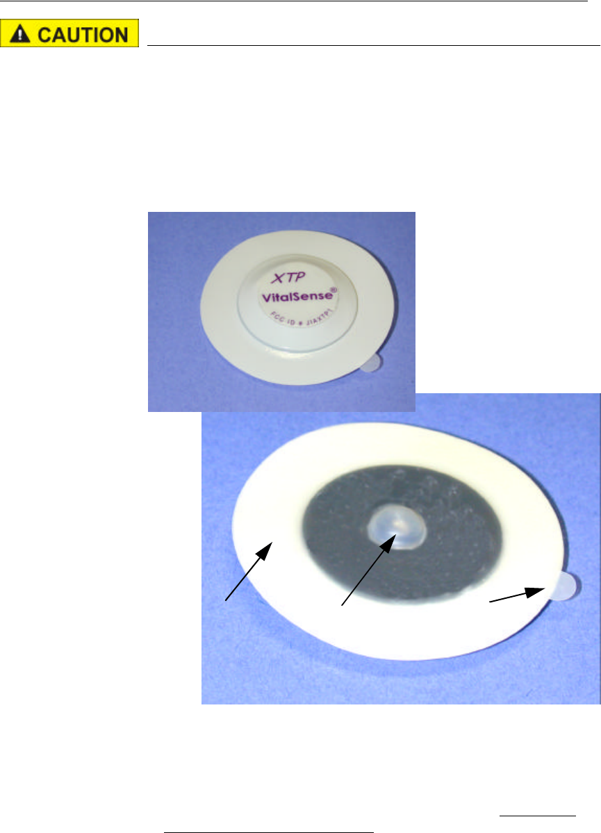
The VitalSense Dermal Patch Sensor is a wireless, miniaturized,
externally activated, temperature monitoring device that is attached to the
skin with a pressure sensitive adhesive (PSA) and a protective layer. There
are precautions associated with this device.
Dermal patch
•DO NOT remove the Dermal Patch Sensor from the package until it is
to be activated.
•DO NOT remove the protective layer prior to activation.
•Activate the Dermal Patch Sensor prior to application. It cannot be
activated once affixed to the body.
Protective layer
Lens
Protective layer release tab
2-6 Monitor Operation and Sensor Activation
Precautions Prior to Activating the Capsule Sensor
Read before activating capsule!
Become familiar with the section “ Notices to Practitioners and Subjects ”
on page-vii. It contains important information you need to know prior to
activating the sensors.
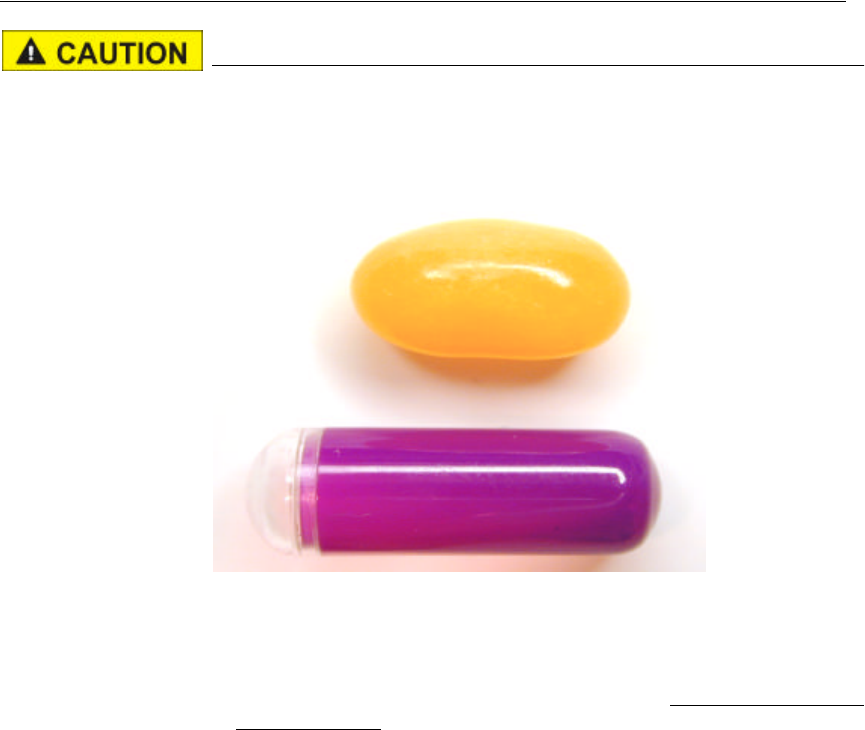
Comparative Size
•DO NOT remove the Capsule Sensor from the package until it is to be
activated.
•Activate the Capsule Sensor prior to swallowing. It cannot be activated
once swallowed.
Capsule Sensor
Jelly bean
2-7
Activating Sensors Using the VitalSense Monitor
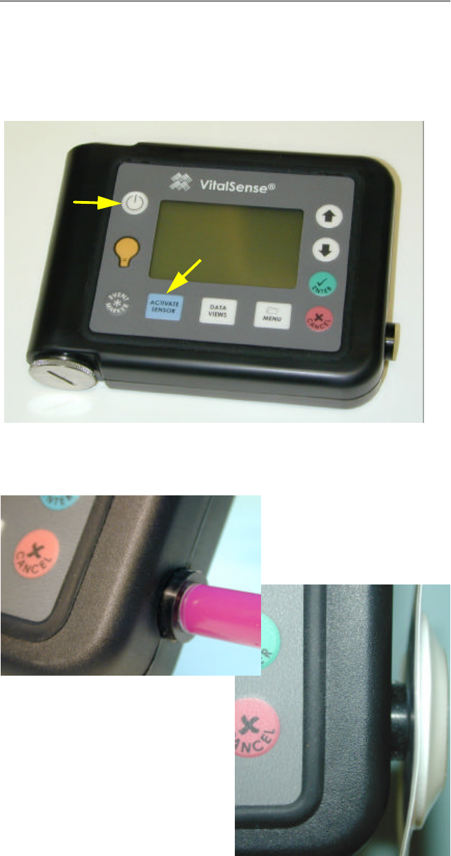
1The process of sensor activation begins by first turning on the monitor.
Press the Power button (see 1 below) and hold for approximately ½-
second.
2Next, press Activate Sensor (see 2 below).
Initiating the activation sequence
Activation 3Follow the directions on the display. Place the sensor lens against the
Activation Port. Press Activate Sensor again.
Activation Port alignment
1
2
Dermal patch sensor
Capsule sensor
2-8 Monitor Operation and Sensor Activation
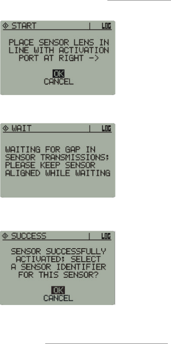
4During the activation prompts (below), do not remove the sensor from
the Activation Port.
Placement for activation
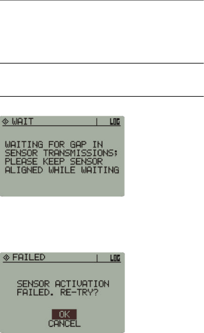
5If other sensors are activated, you may receive the following message.
Waiting for transmission gap
6You will be informed when the sensor has been successfully activated.
Remove the sensor from the activation port.
Activation
Complete Successful activation
As shown above, you are asked if you want an optional sensor
identification, or label. If you choose OK, it replaces the identity number
of the sensor with placement information. Labeling the sensors must be
done at this time. You cannot return to the sensor labeling routine.
2-9
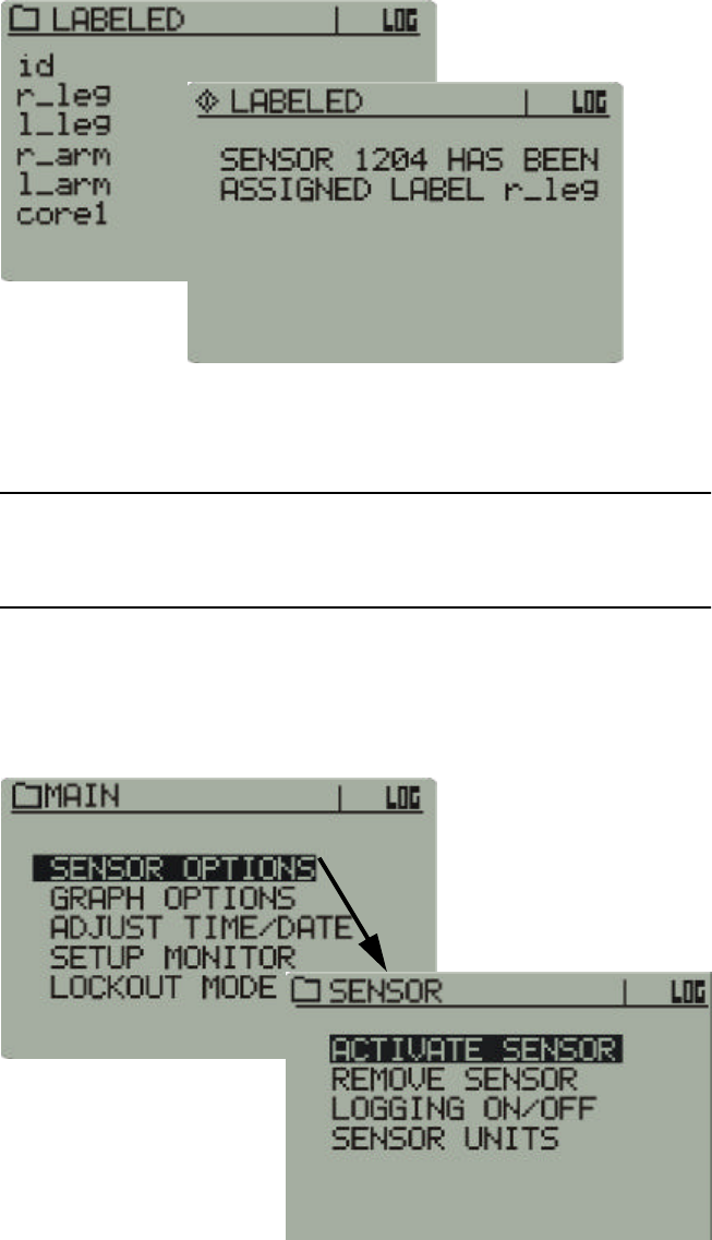
7Use the arrow buttons to choose either OK or Cancel, and press Enter.
8If you choose to label the sensor, use the arrow buttons to choose the
appropriate identifier for the sensor, and press Enter. In the illustrations
below, the Right Leg (r_leg) is the label assigned to sensor 1204.
Sensor
Labeling Activate Sensor > (activated) > OK > Identifier
9Sensor activation is complete. For additional sensors, repeat the
procedure. Up to 10 sensors may be placed on-line per monitor.
NOTE: “id” uses the numeric sensor identification number instead
of a text label.
Sensor activation can also be initiated from the Main menu as shown
below. It is, however, physically easier to hold the sensor and use the
Activate Sensor button.
Alternate activation sequence - Main display > Sensor Options > Activate Sensor

2-10 Monitor Operation and Sensor Activation
Administration
Both the Capsule Sensor and the Dermal Patch contain ferromag-
netic materials incompatible with MRI (magnetic resonance imag-
ing) and should not be worn nor ingested if an MRI is planned. Any
subject ingesting or affixing the above sensors is to wear an MRI
Warning wrist band (supplied with each sensor) as long as the sen-
sors are in place.
Dermal Patch Sensor
1Remove excess hair from the area in which the sensor will be mounted.
2Prepare the skin by cleaning with an alcohol-moistened wipe.
3Following successful activation, use the tab to peel away the protective
layer.
4Affix the Dermal Patch Sensor to the skin.
5Affix an MRI Warning wrist band (supplied) to the subject with
instructions that it is to be worn as long as the Dermal Patch is in place.
Keep the VitalSense Monitor within 2 meters of your body.
NOTE: Avoid the use of lotions and emollients in the area of the
Dermal Patch Sensor. Their uses may cause the adhesive to loosen.
Capsule Sensor
Do not chew. There are metal components inside the capsule. Swal-
low whole with liquid.
1Following successful activation, swallow the Capsule Sensor with
approximately 8-ounces of water, juice, or soft drink.
2Keep the VitalSense Monitor within 1 meter of your body.
3Affix an MRI Warning wrist band (supplied) to the subject with
instructions that it is to be worn until the Capsule Sensor has been
expelled.
2-11
Sensor Does Not Activate
Failure to activate immediately
If the sensor does not activate within a few seconds, it may be waiting for
a transmission from a previously activated sensor. Hold the sensor in
place. Once the transmission has been received, the monitor will activate
the new sensor.
NOTE: As more sensors are brought on-line, the monitor may need
to wait for longer periods.
Activation delay notice
Failure to activate
If a sensor fails to activate, you will be prompted. There may be several
reasons for non-activation.
Sensor activation failed
•Wait approximately 5 seconds and try again.
•Check Data Views to verify that there is no sensor activation.
•Check that the sensor lens is aligned properly with the activation port.
•Attempt to re-try at least 3 times. If still not activated, return the sensor
to Mini Mitter for analysis.
2-12 Monitor Operation and Sensor Activation
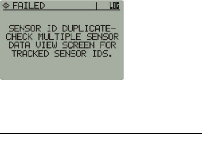
Duplicate sensor
The sensor will not activate if the identification number of the sensor is
identical to one already in the monitor schedule.
Duplicate sensor notice
NOTE: This error is very unlikely. Very few sensors will ever share
the same identification. In the unlikely event this happens, use
another sensor.
2-13
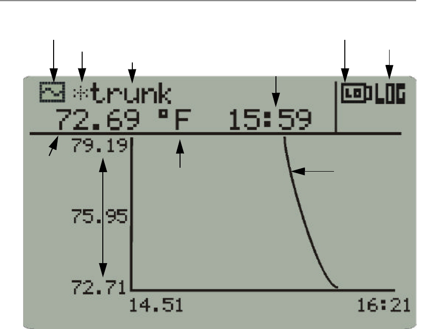
VitalSense Monitor Details of Operation - Display
The Data Graph displays a variety of operational characteristics.
1Display-type - Activation, Menu, or Data View.
2Asterisk - one or more of the last transmissions was missed. If
reacquired, it will disappear.
3Sensor label - option chosen or declined as part of activation sequence.
4Start time - of the logging session.
5Low battery indicator - battery life remaining will depend on the
number of sensors and the acquisition mode of the monitor. See
“ Battery Replacement ” on page4-4 for additional information.
6Logging on - monitor is logging sensor data (change from Menu >
Sensor Options > Logging On/Off).
7Temperature/time curve - a “rolling” curve updated as data are
collected.
8Graph length - determines the number of hours of data displayed
(change from Main > Graph Options).
9Y-Scale minimum and maximum - of the temperatures collected
within the displayed time period.
10Sensor temperature - last temperature acquired from any sensor.
11Sensor units - temperature measurement in Celsius or Fahrenheit
(change from Main > Sensor Units).
1-Display-type icon
2-Missed transmission
6-Logging is on
7-Temperature/time
4-Start time
3-Sensor label
8-Graph length (X)
5-Low battery
10-Sensor
9-Max/Min temp
curve
Temperature
indicator
11-Sensor Units
2-14 Monitor Operation and Sensor Activation
Icon Definitions
•Activation display
•Menu display
•Data View display
•Low battery indicator
•Logging enabled
NOTE: If the VitalSense Monitor display should inexplicably go
blank, momentarily press any button. High discharges of ESD can
cause the display to shut down. See “ Electrostatic Discharge
Effects on Monitor ” on page-x.
2-15
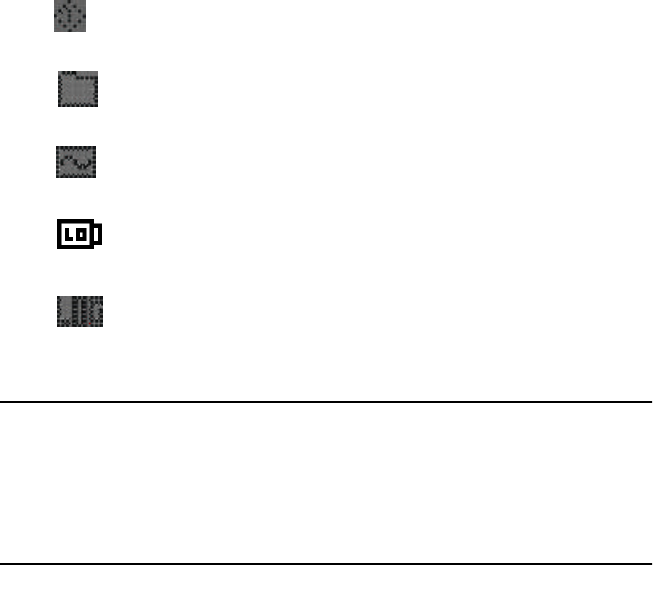
VitalSense Monitor Details of Operation - Menus
The Main Menu is a gateway to several sub-menus.
Sensor Options
Sensor
Options
Activate Sensor
Main > Sensor Options > Activate Sensor
The process described above is identical to the function of the Activate
Sensor button on the front panel of the monitor. See “ Activating Sensors
Using the VitalSense Monitor ” on page2-7.
2-16 Monitor Operation and Sensor Activation
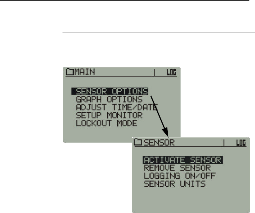
Sensor
Options
Remove Sensor
The Remove Sensor function deletes a sensor from the sensor schedule.
However, data from that sensor, if logged, will be preserved.
Once a sensor has been removed from tracking, the tracking cannot
be reestablished for that sensor.
1Select Remove Sensor from the Sensor Option list.
Main > Sensor Options > Remove Sensor
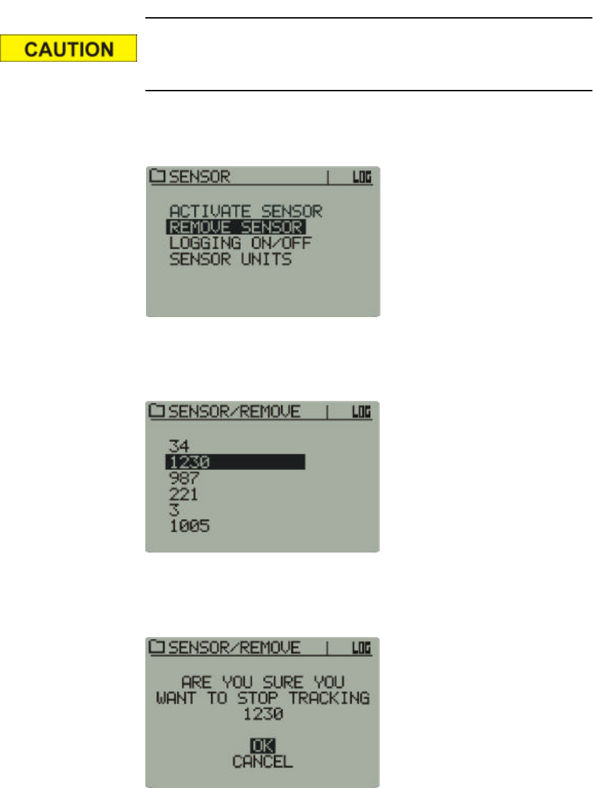
2From the sensor schedule, use the arrow buttons to select the sensor that
is to be removed. Press Enter.
Remove Sensor selection
3If you want to cease tracking and remove the selected sensor, select OK
and press Enter.
Advisory prompt
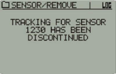
2-17
4The selected sensor is removed from the sensor schedule.
Sensor removed from schedule
2-18 Monitor Operation and Sensor Activation
Sensor
Options
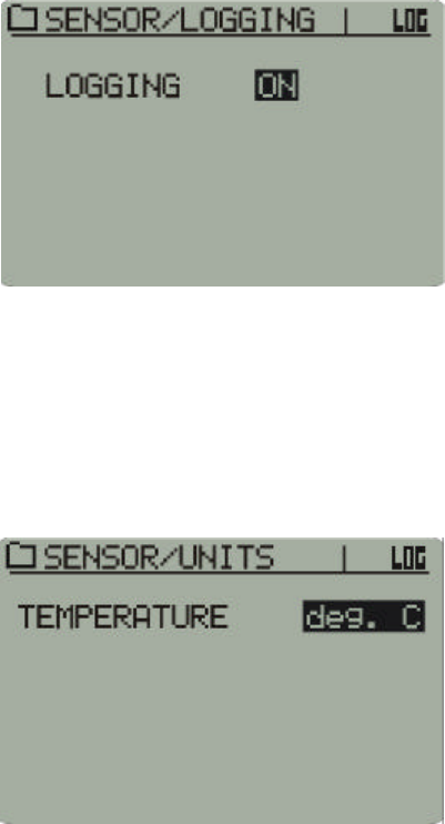
Logging ON/OFF
This function toggles the VitalSense Monitor logging selection ON or
OFF. If turned off, the VitalSense Monitor will continue to communicate
with the sensors, but the data memory will not log the data until logging is
toggled back to ON.
1Use the arrow buttons to select between ON and OFF.
2Press Enter.
Main > Sensor Options > Logging On/Off
Sensor
Options
Sensor Units
Temperatures can be displayed in Celsius or Fahrenheit.
1Use the arrow buttons to select between the two choices.
2Press Enter.
Main > Sensor Options > Sensor Units
2-19
Graph Options
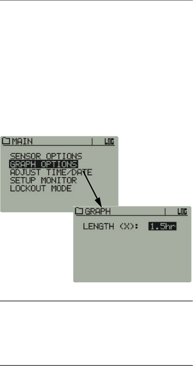
Graph Options
Length (X)
This function sets the length (in hours) of the X-axis displayed in the Data
Views graph. Up to 48 hours of data can be displayed. The following
choices are available. Use the arrow buttons to make the selection, and
press Enter.
•1.5 hours
•3 hours
•6 hours
•12 hours
•24 hours
•48 hours
Main > Graph Options
NOTE: When this parameter is changed while logging is in
progress, the graph will be interpolated or extrapolated to the new
time scale, which may result in empty areas when increasing the
time scale. This has no effect on the integrity of the data being
logged, although the data may not be visible until a new graph is
drawn.
2-20 Monitor Operation and Sensor Activation
Adjusting the Time/Date
When setting the clock, use the arrow buttons to navigate through the
menus and increment and decrement the highlighted choices. Press Enter
to make your selection.
There are two methods by which the clock should be set.
Method A
1Check (or uncheck) Daylight Saving Time Auto-set.
2Set the UTC Offset.
3Set the local time.
If the previous three steps are followed, the UTC clock will be set
automatically.
Method B
1Set the UTC time.
2Set the UTC offset.
3Check (or uncheck) Daylight Saving Time Auto-set.
If the previous three steps are followed, the Local Time will be set
automatically.
NOTE: Although the clock functions are accessible from the moni-
tor front panel, it is much easier and more efficient to change them
from the VitalSense Application Program on the host PC. See “ Set-
ting the Monitor Clock ” on page3-9.
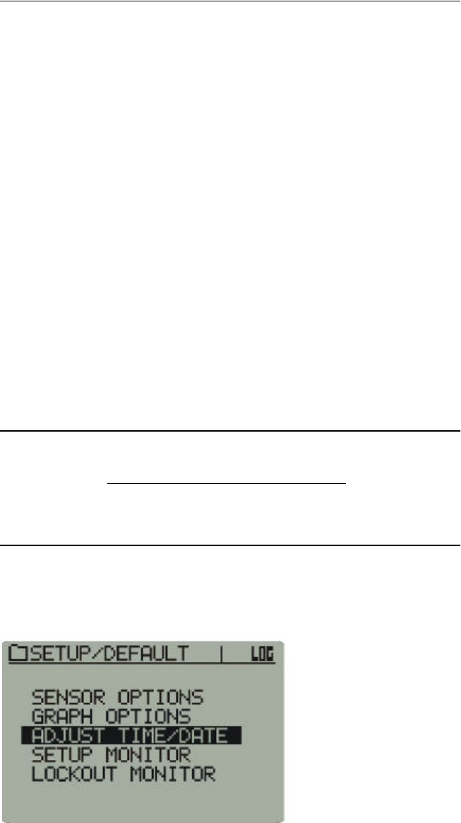
1From the Main menu, use the arrow buttons to select Adjust Time/Date
and press Enter.
Adjust Time/Date
2-21
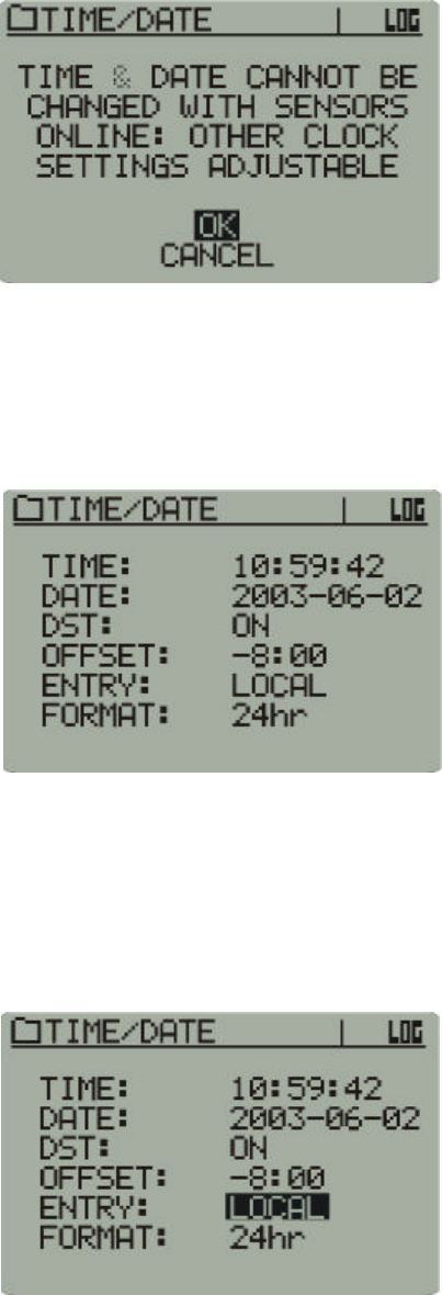
2If you have sensors on-line, you will receive an advisory that the time
and date cannot be changed.
Sensor on-line advisory
3Use the up and down arrow buttons to select either OK or Cancel, and
press Enter.
4The following menu is the Time/Date entry display. To make changes,
use the arrows to navigate to the desired location, and press Enter.
Again, use the arrow buttons to make your selection.
Time/Date menu
Setting the Time and Date
This procedure will set the monitor to Local or UTC time.
1The factory default for the Time/Date menu selection is Local. Use the
arrow buttons to toggle between Local and UTC time.
Local time
2-22 Monitor Operation and Sensor Activation
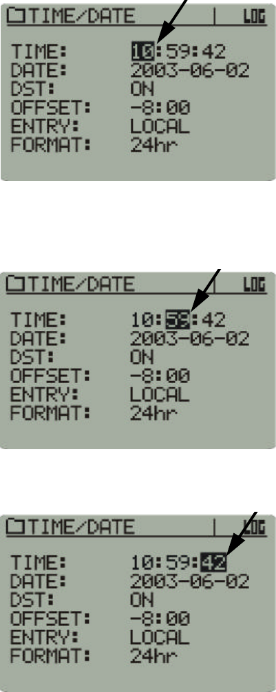
2Use the arrows to navigate to the hour as shown below. (The selection
will default to the hour when the Time/Date menu is selected.) Press
Enter. Use the arrow buttons to increment and decrement the selection.
Press Enter to input the selection.
Hours selected
3Use the arrows to navigate to the minutes. Press Enter. Use the arrow
buttons to increment and decrement the selection. Press Enter to make
your selection.
Minutes selected
4Repeat this procedure to change the seconds.
Seconds selected
2-23
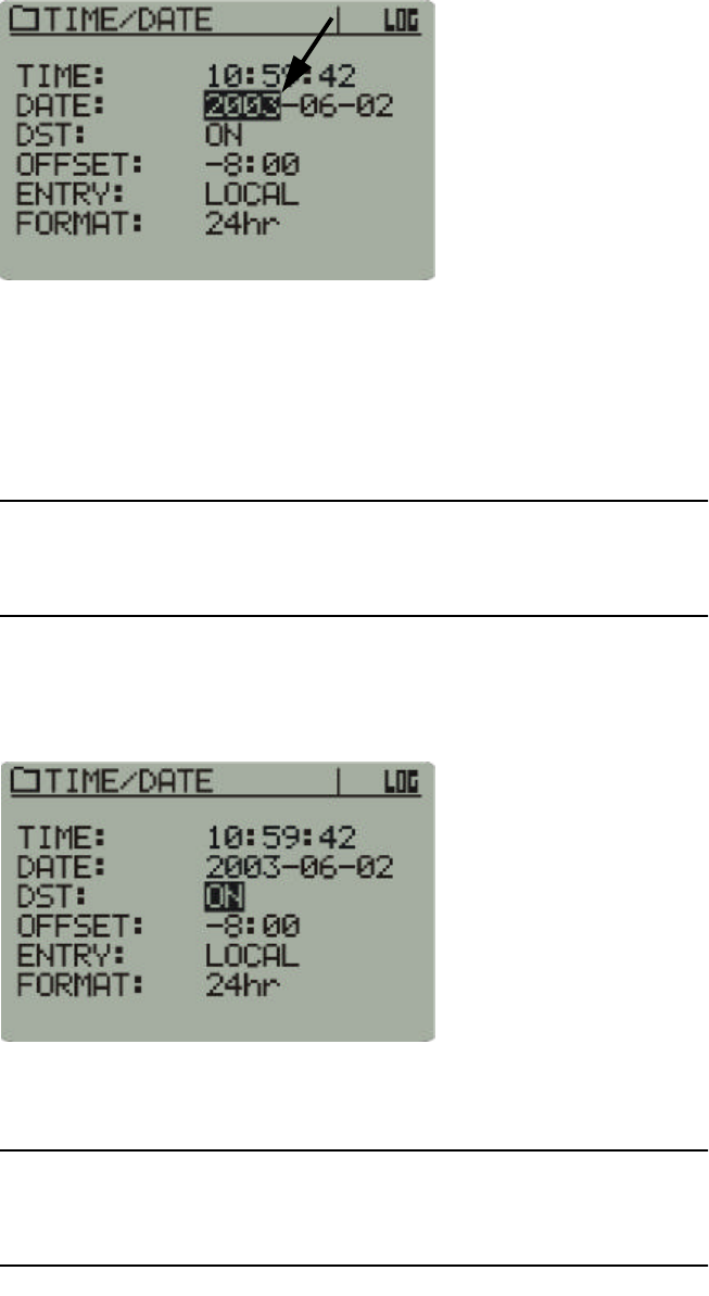
5This procedure is also used to change the date, beginning with the year.
Year selected
Daylight Saving Time Auto-Set
VitalSense will automatically compensate for the change of Daylight
Saving Time to Standard Time and back again based on the monitor’s
time and date settings. However, this feature can be turned off.
NOTE: Automatic Daylight Saving Time should be used only in the
United States, and in those regions observing DST.
1Use the arrow buttons to navigate to DST:, and press Enter. Use the
arrow buttons to toggle between ON and OFF.
Daylight time selected
2Press Enter to make your selection.
NOTE: Every Leap Year, VitalSense will compensate for Leap Day.
No adjustment is necessary.
2-24 Monitor Operation and Sensor Activation
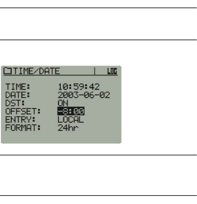
Setting the UTC Offset
The UTC (Universal Coordinated Time) Offset sets the differential
between Local Time and the UTC time, not including Daylight Saving
time. The DST setting may contribute an additional 1-hour offset based on
the date, if enabled. For more information on UTC, see “ A note on UTC ”
on page2-4, and for detailed information see the appendix entitled “
Universal Coordinated Time ” on pageB-1.
NOTE: If the UTC is set correctly, and the correct UTC Offset is
entered, local time will be set automatically.
UTC Offset
NOTE: All data are saved in UTC regardless of whether UTC or
local time is displayed. When data are transferred to the PC, they
can be displayed in UTC or local time.
2-25
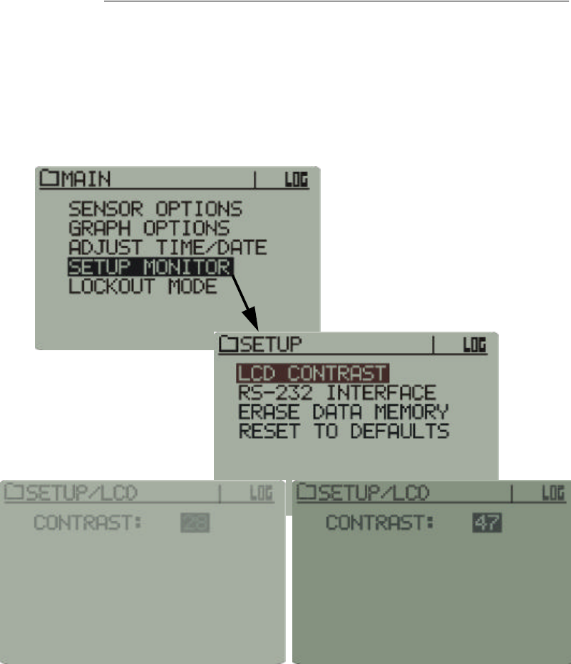
Setup Monitor
Setup Monitor
LCD Contrast
If necessary, the contrast of the LCD can be adjusted.
1Use the arrow buttons to change the contrast.
2Press Enter.
Main > Setup Monitor > LCD Contrast
2-26 Monitor Operation and Sensor Activation
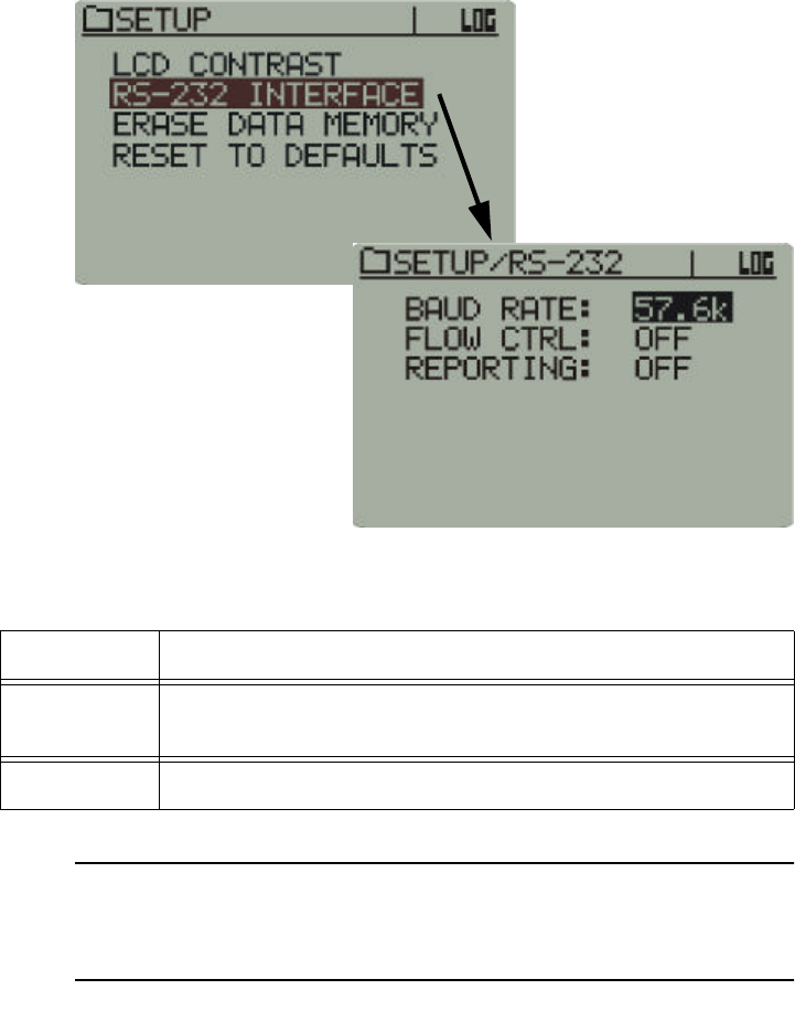
Setup Monitor
RS-232 Interface
It may become necessary to change the RS-232 configuration. The default
configuration is: 57.6 kilobaud, Flow Control: Off.
Main > Setup Monitor > RS-232 Interface
The combinations available are listed in the table below:
NOTE: It is recommended that if you are unfamiliar with these
terms, you leave the settings to the default values.
Baud Rate 2400, 4800, 9600, 19.2 k, 38.4 k, 57.6 k, 115.2 k
Flow
Control ON, OFF
Reporting ON, OFF
2-27
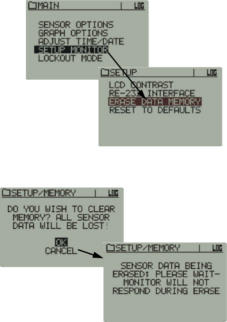
Setup Monitor
Erase Data Memory
Prior to initiating a new session, the data memory should be erased to
provide maximum storage capacity.
1Use the arrow buttons to access Erase Data Memory.
Main > Setup Monitor > Erase Data Memory
2Use the arrow buttons to select OK. Memory erasure will take up to 30
seconds. The monitor front panel functions will be locked out until the
memory is cleared.
Memory erase safety prompt
2-28 Monitor Operation and Sensor Activation
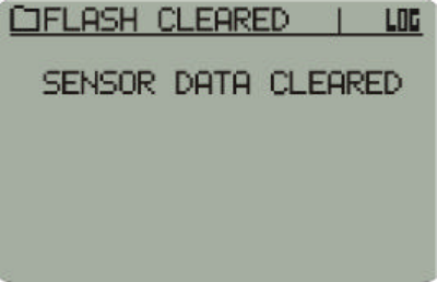
3You will be prompted when the memory is clear.
Memory clear prompt
2-29
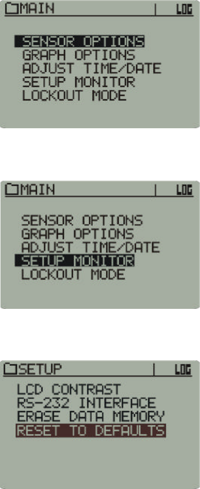
Setup Monitor
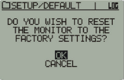
Reset to Defaults
This procedure will return the VitalSense Monitor to the factory
configuration.
1Press the Power button on the monitor front panel. The following Main
menu will appear.
Main Menu
2Using the arrow buttons, highlight Setup Monitor, and press Enter.
Main > Setup Monitor
3Using the arrow buttons, highlight Reset to Defaults, and press Enter.
Main > Setup Monitor > Reset to Defaults
2-30 Monitor Operation and Sensor Activation
4A prompt will appear. Use the arrow buttons, select OK, and press
Enter.
Advisory prompt
The monitor has now reset to the factory default settings.
2-31
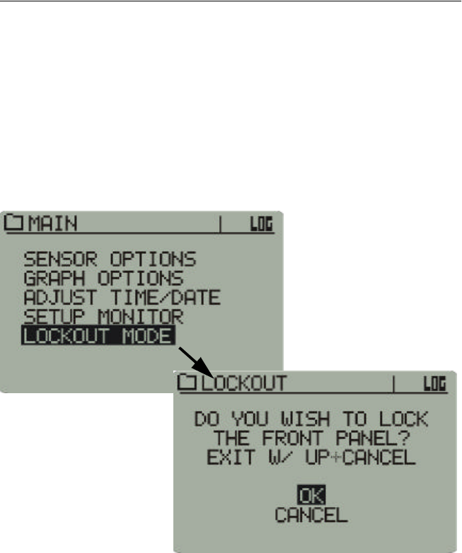
Lockout Mode
Lockout Activate
Lockout Mode enables the practitioner to lock the front panel functions to
discourage unauthorized tampering of the settings, or to prevent accidental
activation of front panel buttons while the monitor is in the carrying
pouch.
1Use the arrow buttons to select Lockout Mode.
2Use the arrow buttons to select OK, and press Return to activate.
Main > Lockout Mode
Lockout deactivate
To deactivate Lockout Mode, press and hold the up arrow, and press
Cancel. Normal operation of the front panel will resume.
2-32 Monitor Operation and Sensor Activation
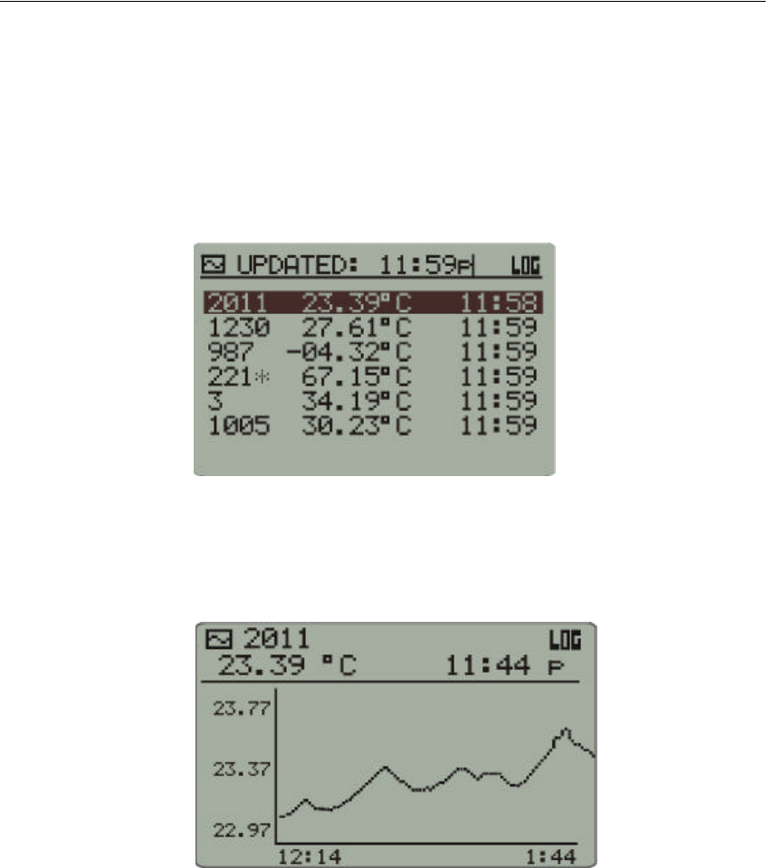
Data Views
Pressing the Data Views button on the VitalSense Monitor front panel will
toggle two means by which to view the sensor data: Sensor List and Data
Graph.
1On the monitor front panel, press the Data Views button. A list of
sensors will be displayed along with the temperature and time stamp.
(Use the up and down arrows to view sensors which may not be visible
on the display.)
Sensor List Sensor List
Data Graph 2To view a sensor in Data Graph mode, highlight the sensor using the
arrow buttons, and press Data Views once more. To adjust the amount
of time shown on the X-axis of the graph, see “ Graph Options ” on
page2-19.
Data Graph
3You may toggle between Data Graph and Sensor List with the Data
Views button. To view other sensors in Data Graph mode, use the
arrow buttons to highlight the sensor of interest and press Data Views
once more.

2-33
Out-of-Range Conditions
With respect to periodic hygiene, change of clothing, decontamination,
and other related tasks, it may be necessary to remove the VitalSense
Monitor from the working range of the sensors for short periods of time.
The VitalSense Monitor may be removed from sensor range for up to 30
minutes. Beyond 30 minutes, VitalSense may have difficulty
resynchronizing with sensor transmissions, and a significant loss of data
may occur. Previously logged data will be preserved in the monitor, but
future data collection may not be possible in Standard Mode.
An asterisk will appear beside any sensor for which the last data
transmission was missed. The value displayed will be the last valid data
for that sensor. The time shown will be when the last reading was
recorded.
2-34 Monitor Operation and Sensor Activation