Mini Mitter XTP1 Integrated Physiological Monitoring System User Manual Tinman Book
Mini Mitter Co. Inc. Integrated Physiological Monitoring System Tinman Book
Contents
- 1. Users Manual
- 2. Users Manual part 1
- 3. Users Manual part 2
Users Manual part 2

3-1
SECTION
3
C
HAPTER
3
V
ITAL
S
ENSE
O
PERATION
-
A
PPLICATION
P
ROGRAM
Introduction
The VitalSense Application Program is a software utility that
communicates with the VitalSense Monitor via an RS-232 cable. With this
link, a variety of functions can be accomplished from the host PC.
Functions of VitalSense Application Program
•Establish communication with VitalSense Monitor
•Load Subject Information into VitalSense Monitor
•Turn off logging function of VitalSense Monitor
•Set the on-board clock VitalSense Monitor
•Drop a Sensor from VitalSense Monitor Sensor List
•Real-time viewing of temperature data from VitalSense Monitor
•Erase the subject/sensor data, and the temperature data from VitalSense
Monitor
•Retrieve data from VitalSense Monitor
•Identify firmware of VitalSense Monitor
•Load updated firmware version into VitalSense Monitor

3-2 VitalSense Operation - Application Program
PC Preparation Prior to Installation
PC
Requirements
for VitalSense
•IBM®-compatible PC
•Pentium® II processor with a clock speed of at least 350 MHz
•64 MB of RAM
•Windows® ‘98, 2000, XP, Millennium, or Windows NT 4.0 SP 6
•CD-ROM drive
•4 MB of free space on the hard disk
•9-pin or 25-pin RS-232 communications serial port, or USB port with
USB-to-serial adapter
•Super Video Graphics Array (SVGA - 800 x 600 pixels required to
view all data displays)
•Printer (optional)
NOTE: Recommended is a Pentium® III or IV Processor, 866 MHz
to 1+ GHz, and 128MB or more of RAM.
Preferred
Settings VitalSense software is best used with the following computer display
settings. Directions for changing these settings can be found in the On-line
Help feature of your specific operating system.
Monitor area or monitor resolution
Set the resolution for 800 x 600 or higher. 1024 x 768 is
recommended.
Appearance scheme (or theme)
Avoid “High Contrast” or “Extra large” schemes. Windows
Standard is recommended.
Font sizes
Select “Normal” or “Small font” (font sizes of 12 points or less).
Eight-point is recommended because it will allow you to see more
information than larger font sizes.

3-3
Installation of Software
NOTE: Before beginning the installation procedure, make sure that
no other applications are currently running on the host PC. This
includes MS Office® and any other utilities. These can interfere with
proper installation, resulting in software conflicts.
The VitalSense Application Program software is distributed as a
MicroSoft® Installation package (.msi) file.
If you have Windows® 2000 or XP, simply double-click on the filename
and follow the instructions. The default installation path is \Program Files\
VitalSense.
Earlier versions of Windows may require installing the Microsoft Installer
program on your computer. This program can be obtained as a free
download from the Microsoft Website. A copy of Microsoft Installer
version 2.0 for Windows 95/98/ME (InstmsiA.exe), and for Windows NT
SP6/Windows 2000 (InstmsiW.exe) is supplied on the VitalSense CD.
Windows XP comes with Microsoft Installer 2.0 pre-installed.
3-4 VitalSense Operation - Application Program
Connecting VitalSense Hardware
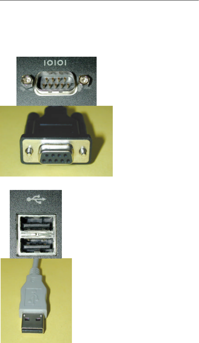
Serial COM Port
Today’s computers typically have either a 9-pin DB9 serial port or a USB
(Universal Serial Bus) port. These will look similar to the ones pictured
below.
9-pin Serial COM ports
USB ports
Computer connector
Cable connector
Cable connector
Computer connector
3-5
The 9-pin serial cable is the type supplied with your system. If your
computer does not have a 9-pin serial port, it is suggested that you obtain a
9-pin to USB adapter. These are available at most computer supply or
electronics stores.
1Plug the 9-pin DB9 connector into an available COM port on the PC.
2Plug the miniature 5-pin barrel connector into the VitalSense Monitor.
For proper insertion, align the dot on the barrel connector with the dot
on the monitor connector.
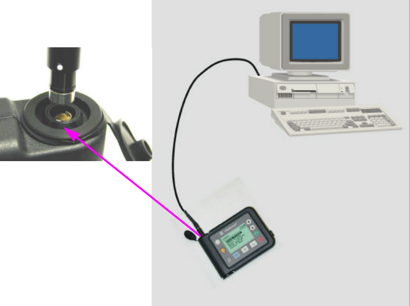
Connecting VitalSense to computer
The hardware connections are complete. The next step will be starting the
VitalSense Application Program, and then establishing communication
between the PC and monitor via the serial COM port cable.
Align the dots
3-6 VitalSense Operation - Application Program
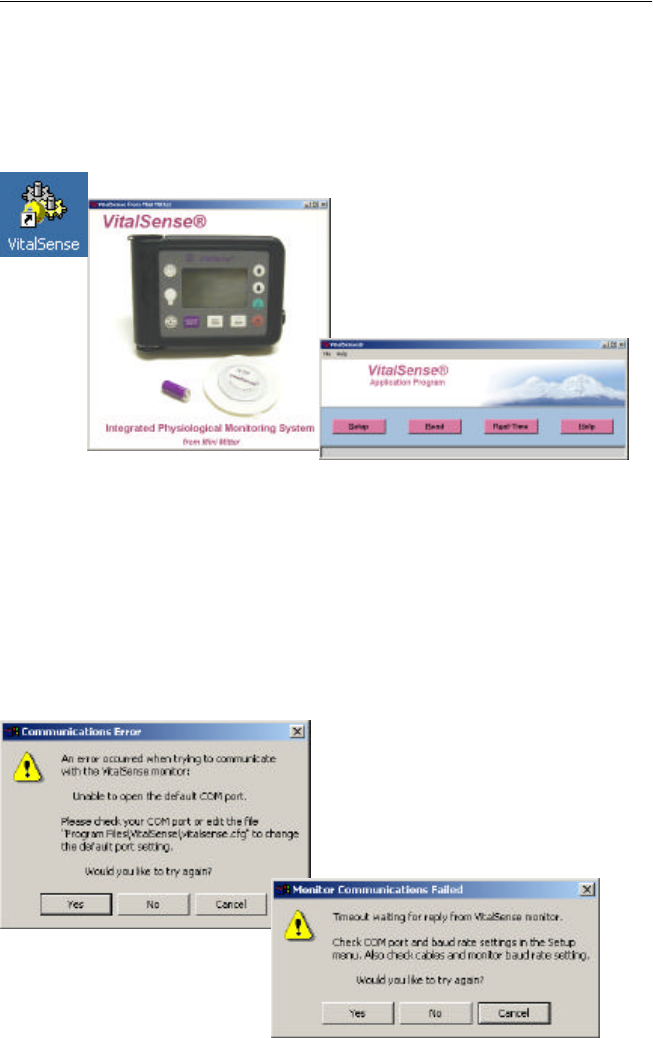
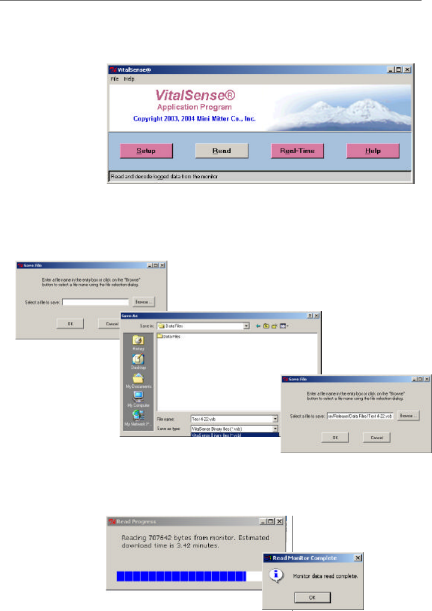
Starting the VitalSense Application Program
1Turn on the VitalSense Monitor by pressing the Power button.
2Start the VitalSense Application program. Click on the shortcut
established on your desktop during installation. An introductory splash
display should appear, followed by the Main window.
VitalSense shortcut icon
No communication errors?
If there are no communications errors, you have established
communications with the VitalSense Monitor. Proceed to “ Monitor
Setup for Data Collection ” on page3-8.
Typical communication errors
You may receive one of two communication errors. This is not unusual.
The most likely reasons for communication errors are:
•COM port 1 is being used by other hardware, e.g., printer, scanner.
•VitalSense defaults to COM port 1. The serial COM port cable is
plugged into another port other than COM port 1.
Proceed to “ COM Port Setup ” on page3-7.
Main window
Splash display
3-7
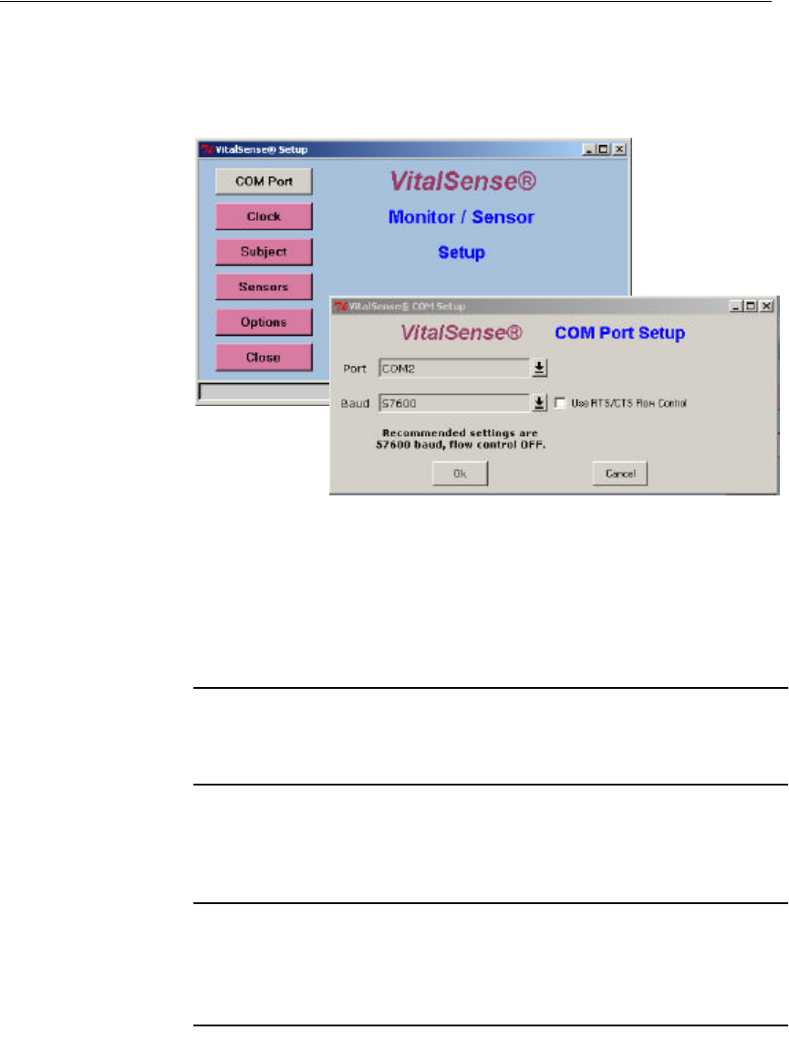
COM Port Setup
If necessary, you may change the COM port with which your computer
communicates with VitalSense, as well as baud rate and flow control.
1Click on Setup, then click on COM Port.
Main > Setup > COM Port
2Select the COM port using the drop-down menu.
3Select the baud rate.
4Check or uncheck the Flow Control box.
5Click OK.
NOTE: The recommended (and factory defaults) for baud rate and
flow control 57,600 and flow control OFF respectively.
6Attempt to communicate with the monitor. This may be done by exiting
VitalSense and restarting the Application Program.
NOTE: You may also test the communication link by attempting a
function such as reading the monitor clock. See “ Read Monitor
Clock ” on page3-10.
If, after repeatedly changing the COM port selection, you cannot establish
communication with the monitor, refer to “ Establishing RS-232
Communications - Advanced ” on page3-24.
3-8 VitalSense Operation - Application Program
Monitor Setup for Data Collection
Setup for Data Collection from the VitalSense Application Program is
very similar to portions of “ VitalSense Monitor Operation ” on page2-1.
This section, however, contains instructions on additional functions, such
as retrieving data and real-time observation of data collection.
Before data collection can begin, the monitor must be set up, or
configured. This configuration can be done from the host PC through the
RS-232 port of the monitor.
There are three requirements that may have to be accomplished before the
monitor will collect data.
NOTE: The following are somewhat similar to the steps used when
configuring the monitor from the front panel (see “ Monitor Setup
for Data Collection ” on page2-4).
•“ Clear Memory ” on page3-10
•“ Setting the Monitor Clock ” on page3-9
•“ Subject Information ” on page3-11
Some or all of the items may not be necessary. If, for example, you have
configured the VitalSense Monitor previously, erased the memory, or if
you have already set the time.
These steps are generally in the same order in which the monitor should be
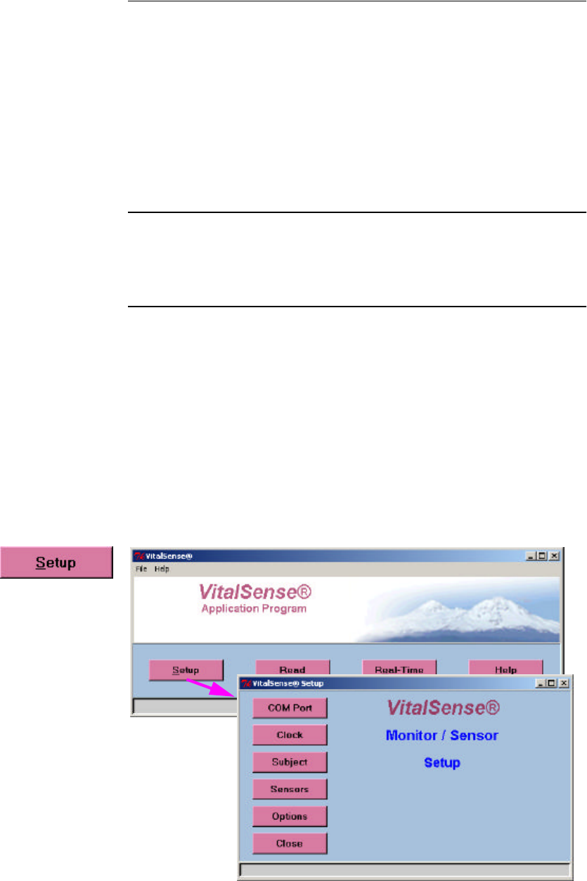
configured. Setup begins with the Main display, and the Setup menu.
Main > Setup
3-9
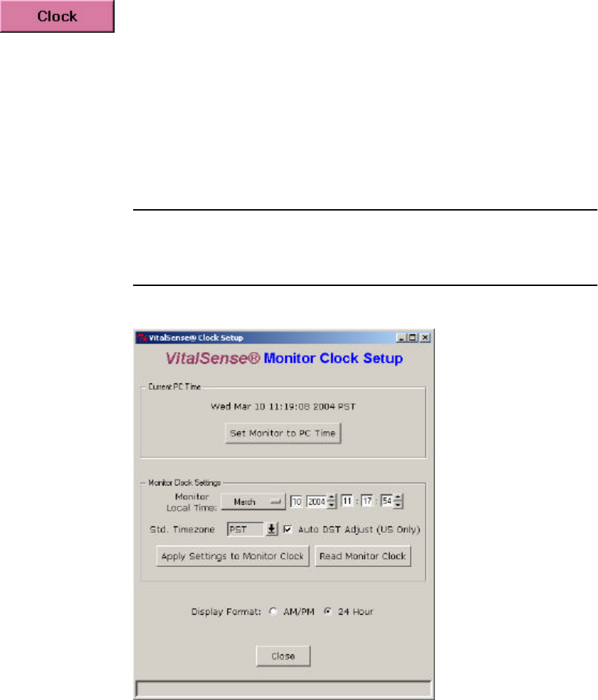
Setting the Monitor Clock
The Clock Setup is accessed from the Main window.
To void confusion, the following steps should be accomplished in order. If
done in this manner, the UTC clock will automatically be set as well as
local time.
•Set the local time.
•Set the UTC Offset.
•Check (or uncheck) Daylight Saving Time Auto-set.
NOTE: You cannot change Monitor Clock Settings functions with
sensors on-line.
Main Window > Setup > Clock
3-10 VitalSense Operation - Application Program
Read Monitor Clock
This function will enable you to read the on-board monitor clock, and will
display it in the Monitor Clock Settings fields.
There are two ways to change the time in the VitalSense Monitor from the
Application Program.
Manually Set Monitor Time
•Selectively set each field individually, then click on Apply Settings to
Monitor Clock button.
Set Monitor to PC Time
•Click on Set Monitor Clock to PC Clock. The PC time will be entered
into the VitalSense Monitor automatically.
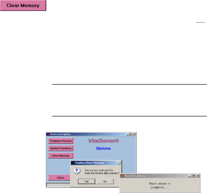
Clear Memory
The VitalSense Monitor uses a portion of its memory for data, and another
portion for subject and sensor information. Clear Memory erases the data
portion of the memory, i.e., the temperature information sent by the
sensors. The data memory pertains only to data, not the sensor or subject
information. Making changes within the Subject Information function will
erase the subject and sensor portion of the memory.
•If you have downloaded the data from an on-going experiment, you
may Clear Memory and begin another data collection session with the
same subject/sensors information.
•If you are beginning a new experiment, you should Clear Memory.
NOTE: If you plan to change or delete subjects, this step may be
skipped. You will be given the opportunity to clear the data memory
later.
Main > Setup > Options > Clear Memory
3-11
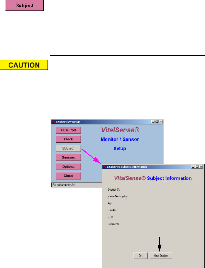
Subject Information
Subject Information is the identification information that the practitioner
can download to the VitalSense Monitor using the Application Program.
The VitalSense Application Program uses a wizard to gather subject
information. This wizard is accessed from the Setup window.
The Subject Information is provided to identify the monitor and data
collection session, therefore only one Subject is possible.
This wizard will assist you in assigning subject information. How-
ever, it will also allow you to erase the data memory as well as cur-
rent sensor assignments. Pay close attention to the prompts.
1From the Setup window, click on Subject. To enter a new subject, click
on New Subject (arrow below).
Main window > Setup > Subject
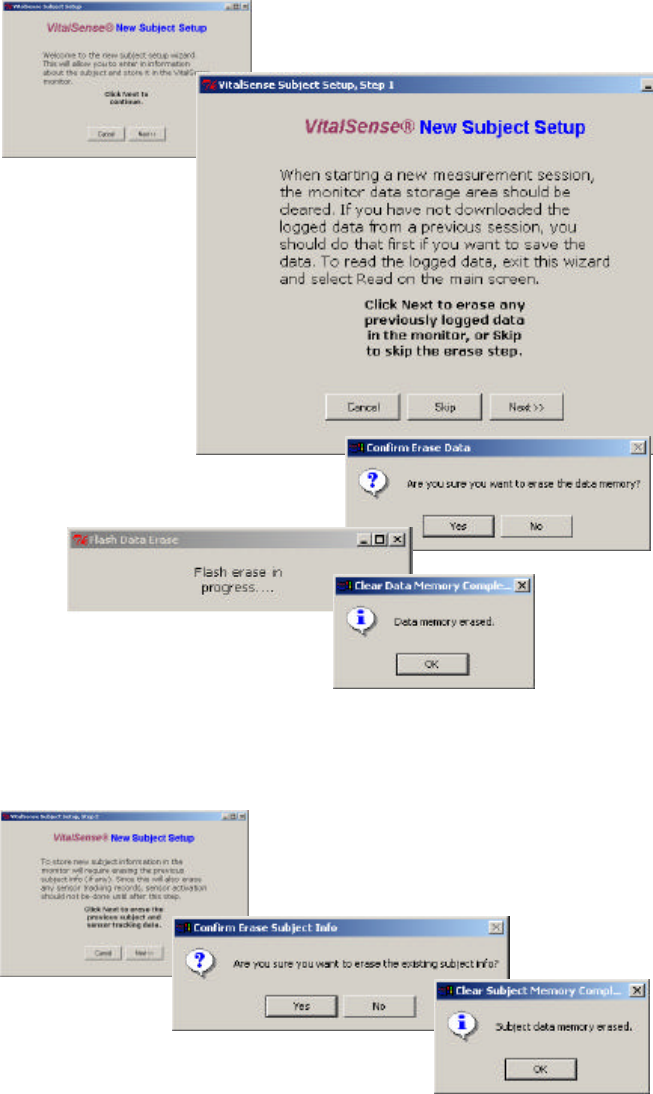
3-12 VitalSense Operation - Application Program
2The wizard will suggest you download any previously acquired data,
and then gives you the opportunity to erase the data memory. By
clicking on Next and the confirmation prompt Yes, the data memory
will be erased. The subject and sensor data will remain.
Data memory erasure
3Entering a new subject, however, will result in the erasure of any
previous subject and sensor information.
Subject data erasure
3-13
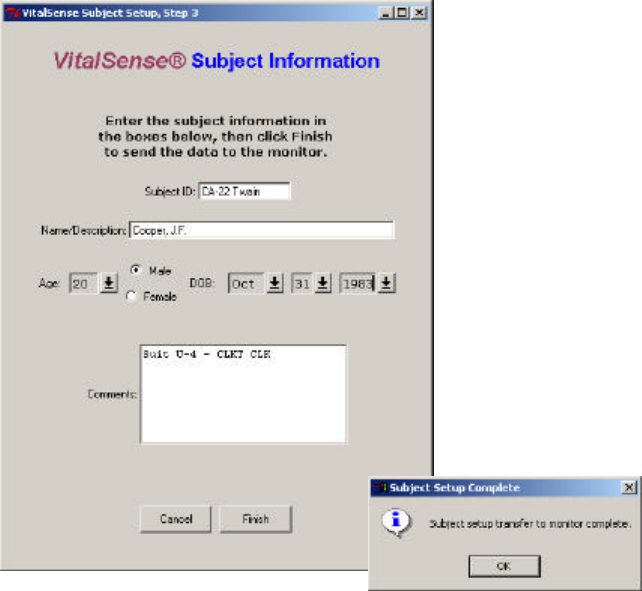
4New subject data can now be entered. Age and date of birth may be
entered using the arrows, or double-click-and-enter in each field.
5Click Finish to complete the entry.
New subject information display
3-14 VitalSense Operation - Application Program
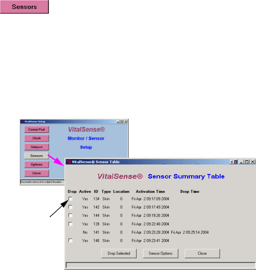
Sensors
Sensor logging may be toggled on or off, or the sensor dropped from the
activated sensor list. Follow the prompts as shown below.
Drop Sensor Drop Sensor from Sensor Summary Table
1From the Main menu, click on Sensors.
2Check the Drop boxes of the sensors you want to drop from the
activated list.
3Click on Drop Selected. The sensor will no longer appear on the Sensor
List. To acquire the sensor list on the VitalSense Monitor, press the
Data Views button on the front panel. See “ Data Views ” on page2-32.
Main window > Sensors
3-15
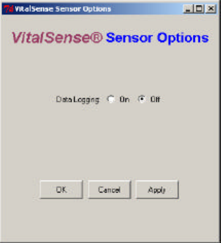
Logging On/
Off Data Logging On or Off
This function turns the logging function of the VitalSense Monitor on or
off. This effects data collection on all sensors, without regard to which
sensors have been selected in the Activated Sensor Table (see previous
function).
1From the Activated Sensor Table, click on Sensor Options.
2Click on Data Logging On or Off.
3Click OK or Apply to enter your selection.
Main > Sensors > Sensor Options
3-16 VitalSense Operation - Application Program
Read Data
This function retrieves recorded data from the VitalSense Monitor.
1Read is accessed from the Main window. Click on Read.
Main Display
2You will be prompted to name the file where this data are to be saved,
and select a location. You may either type in the path or use the browser
to select the location.
Read data
3The data may be saved as a VitalSense Binary File (.vsb), the default,
or a text file (.txt). Name the file, choose its location, and click on Save.
You will be prompted on the progress of the data retrieval.
Data retrieval progress
3-17
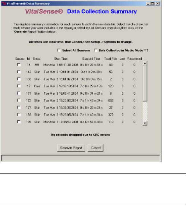
A Data Collection Summary will appear. This is essentially an “index” of
the data collected.
Data Collection Summary
NOTE: If you choose not to generate a report at this time, you may
use the Open File command and generate a report at a later time.
VitalSense Data Collection Summary
The table of sensors as shown above contains the following information
for each sensor listed:
•Extract - Check box that selects the data that will appear in the report.
•Sensor ID - Number assigned sensor at factory.
•Sensor type - Core (Capsule Sensor), Skin (Dermal Patch Sensor).
•Start Time - Time stamp of first data record for that sensor.
•Elapsed time - The time elapsed to last data record for that sensor.
•Total pkts - Number of measurement records.
•Lost - Number of lost packets (records with a time stamp outside the
allowable window of 18.75 seconds).
•Recovered - Number of recovered packets (a missing measurement
recovered from the “previous value” field on the next data packet).
3-18 VitalSense Operation - Application Program
•Data Collected in Medic Mode™ - When checked, lost packet
detection is disabled, since it is unknown when a packet is expected to
arrive. (Medic Mode is a VitalSense Monitor option.)
•Generate Report - Begins the file extraction and decoding process.
•Cancel - Disables the extraction and decoding process.
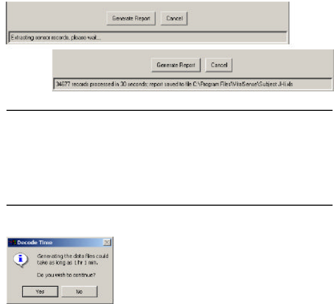
Generate Report
This function will generate two files (explained below).
1Choose the sensors that will appear in the report.
2Click on Generate Report.
You will be prompted on the generation progress.
Report generation progress
NOTE: If the estimated time to generate the report will exceed two
minutes, a prompt will indicate the approximate time required to
generate it (see below). The processing time is affected by the num-
ber of sensors and data records selected, the PC’s CPU speed, and
any other tasks that may be running concurrently on the PC.
Excessive time prompt
3-19
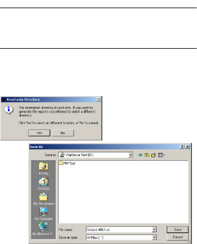
NOTE: The report will generated and then written by default to the
same location as the raw data (.vsb) file. You must have Write per-
mission for that directory.
The following is an attempt to read a .vsb file from a CD. The VitalSense
Application Program asks for another destination for the report because it
cannot write to a CD.
Prompt to change report destination
Output Files Two output files will be generated. Both files will be named with the
original Read Data filename. To rename, use Windows Explorer.
•A Microsoft Excel file with an .xls extension. The filename will remain
identical to the original Read Data filename.
Final download 23Oct04.xls
•A plain text file with a .txt extension. The filename for the text file will
be comprised of the original Read Data filename, along with “_d_nnn.”
“nnn” is the sensor number. “d” stands for “devices(s).” For example:
Final download 23Oct04_d_141_70_142_71_143_144_139.txt
3-20 VitalSense Operation - Application Program
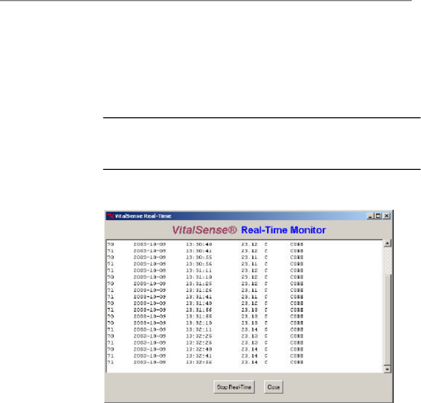
Monitoring Data in Real Time
Monitoring in Real Time allows data collection to be observed as it is
being saved.
1From the Main window, click on Real Time.
2You will be asked where the information is to be saved, and to name the
file. Once named, click OK.
3The following window will fill as the data begin to be retrieved.
NOTE: There is a delay of one sample interval in the time the data
appears on the PC display.
Real-time data
4Click Close to stop the observation in real time. The data will continue
to be saved in the file named in Step 2.
3-21
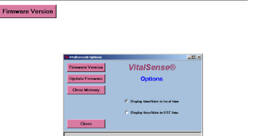
Application Program Options
Firmware Version
Clicking on this feature will query the monitor for the firmware version
currently on board the VitalSense Monitor. This information is
particularly useful when calling Mini Mitter for Technical Support.
Main > Setup > Options
Display Time
The two buttons enable either the local time or UTC time to be shown on
the display.
3-22 VitalSense Operation - Application Program
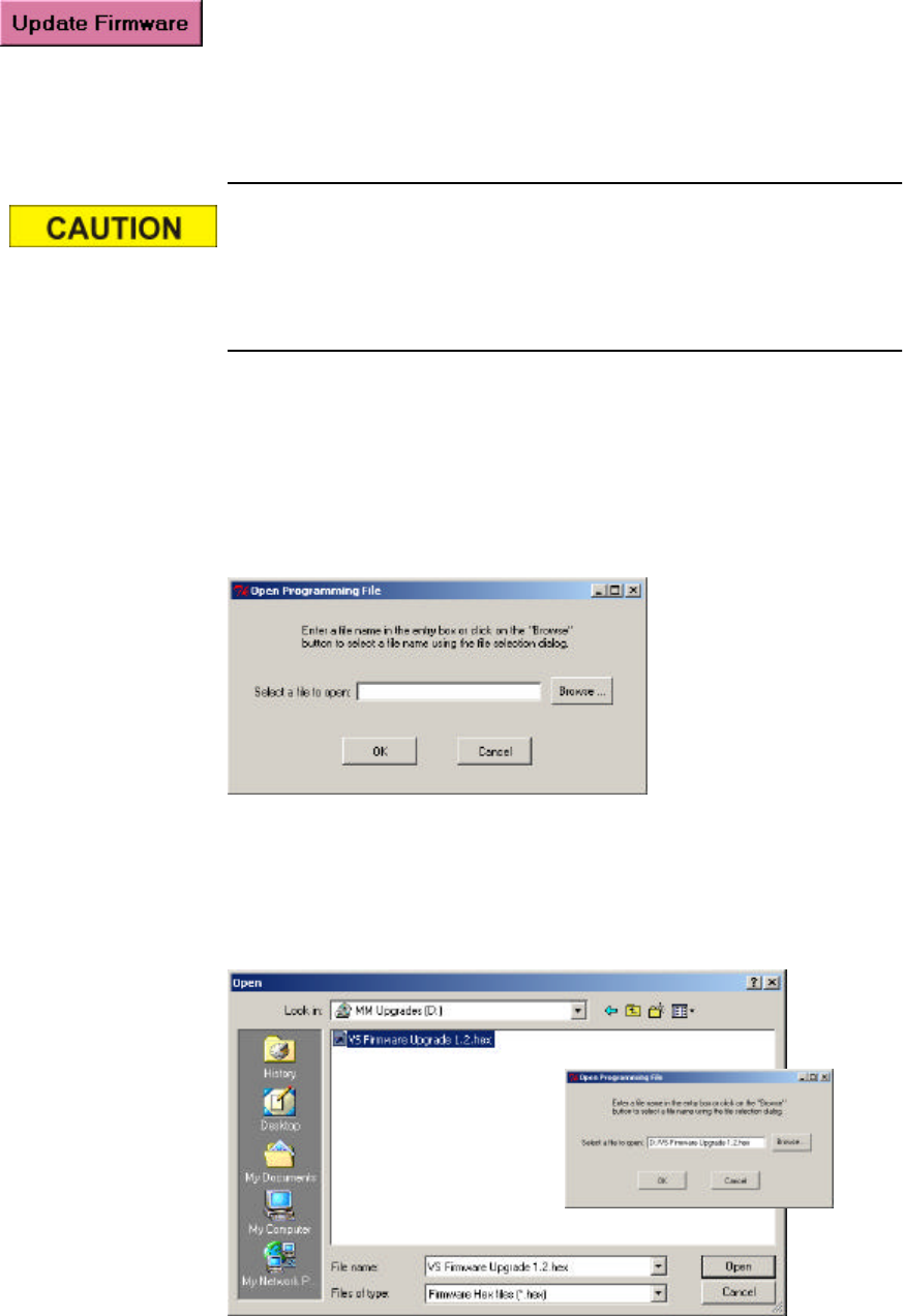
Update Firmware
Periodically new firmware may be released by Mini Mitter Company, Inc.
These releases may be made by CD, Website, e-mail, or other means.
Without regard to the distribution, the following process is to be used to
upgrade the firmware.
This procedure will erase all portions of the VitalSense monitor
memory. All setup and data information will be lost. If data are in
the memory, you must download prior to beginning the upgrade
procedure.
1The VitalSense Monitor must be connected to the host PC, and
communication established (see “ Connecting VitalSense Hardware ”
on page3-4).
2Begin from the VitalSense Options window. Click on Upgrade
Firmware. The following display will appear.
Main > Setup > Options > Firmware Upgrade
3Use the browser to navigate to the source of the firmware. In this case,
the firmware upgrade is located on a CD. Select the appropriate file. It
will have an .hex extension as shown below. Click on Open, and the
selected file will appear in the upgrade field.
Firmware file selection
3-23
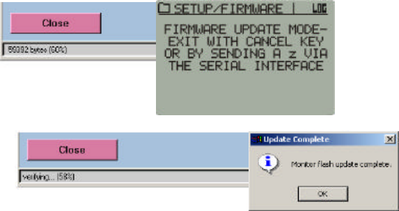
4Click on OK. Progress can be verified from the PC and the monitor.
Once downloaded, the firmware upgrade will be verified. When
verified, a prompt will confirm that the upgrade is completed.
Download progress
Clear Memory
See “ Clear Memory ” on page3-10.
3-24 VitalSense Operation - Application Program
Establishing RS-232 Communications - Advanced
When there is a failure to communicate via the serial RS-232 cable,
typically the cause is one of two major COM port errors:
•COM port is already in use.
•General communication errors
NOTE: This following procedure requires modification of the con-
figuration file. If you are inexperienced or uncomfortable with this
procedure, contact your System Administrator for assistance.
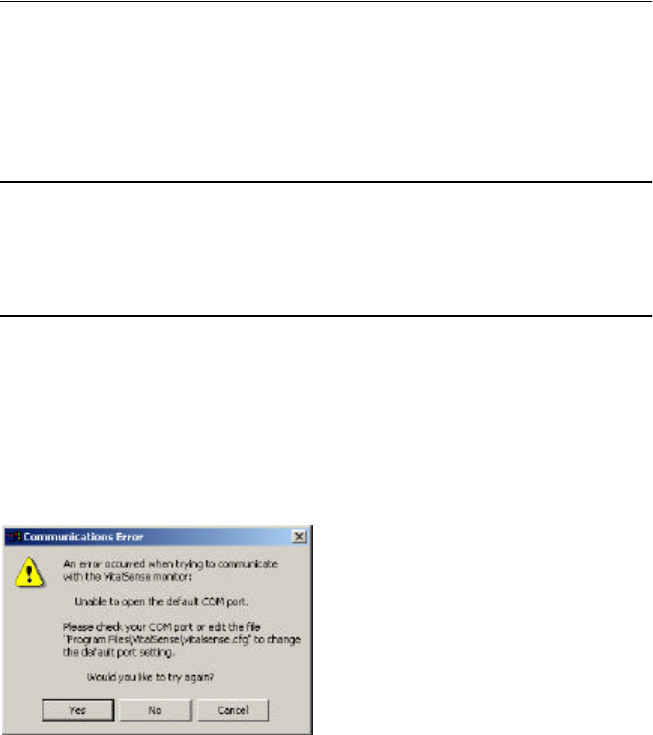
COM Port Already in Use
The VitalSense Application Program default COM port is COM1. If the
following error appears, the COM1 port must be changed. This is done by
editing the configuration file.
COM port advisory
1Open the configuration file using Wordpad, Notepad, etc. This file is
located in the VitalSense installation folder:
Program Files\VitalSense\vitalsense.cfg
2Change the second line in the file to match an available COM port, e.g.,
COM2.
3Save the file and restart the VitalSense Application Program.
3-25
General Communication Error
In this type of error, the program can open the serial port, but cannot
establish communications with the VitalSense Monitor.
COM port advisory
1Check the serial cable connection at the PC, and at the VitalSense
monitor.
2Verify the default baud rate of the VitalSense Monitor is set to
57.6 kilobaud. This can be found from the monitor front panel.
Use the following path:
Setup > RS-232 Interface > Baud Rate: 57.6k
If it is not, use the arrow buttons to select 57.6k and press Enter.
3Additional information can be obtained by opening the VitalSense
console window. This diagnostic information may be of use to you, or
in case you need to contact Mini Mitter Technical Support. To access,
click on VitalSense in the Windows task bar.
The console lists important errors that may have occurred in the
VitalSense Monitor.
VitalSense diagnostic console
Once communication has been established via the RS-232 cable, setup and
data collection can begin.
Click here for console
3-26 VitalSense Operation - Application Program
USB Adapter
Persistent RS-232 Errors
If you still have difficulty establishing communications with the
VitalSense Monitor, it may be necessary to use a USB to serial adapter.
Some brands of laptops have demonstrated peculiar problems due to
hardware and/or driver incompatibility. The use of a USB-to-serial port
adapter will require you to install the new driver supplied with the adapter,
and this may result in successful communication.
A USB-to-serial port adapter may be purchased from Mini Mitter
Company, or your local computer store. The recommended adapter type at
this printing is the Aten® UC232A.
Installing the USB Adapter
1To install the proper drivers, follow the directions included with the
adapter.
2Connect the adapter to the USB port on your computer.
3Use the Windows Device Manager to find the COM port assigned by
the adapter driver. See the Windows help function for instructions.
4Once the assigned COM port is known, enter the port number in
VitalSense Application Program Setup (see “ COM Port Setup ” on
page3-7).

4-1
SECTION
4
C
HAPTER
4
M
AINTENANCE
This section applies to the VitalSense Monitor, including hardware
maintenance such as battery replacement and cleaning.
The VitalSense Monitor uses a very specific battery. When replac-
ing the battery, use only a lithium 3.6 volt AA-size battery (SAFT
LS 14500). Any battery other than the one specified may cause
damage to the circuitry of the VitalSense Monitor, or cause reduced
performance. Do not attempt to recharge the lithium battery.
NOTE: The sensor batteries cannot be replaced.
Do not dispose of lithium batteries in fire or flame. An explosion
may result. Only dispose in accordance with manufacture’s recom-
mendation, or local codes.
4-2 Maintenance
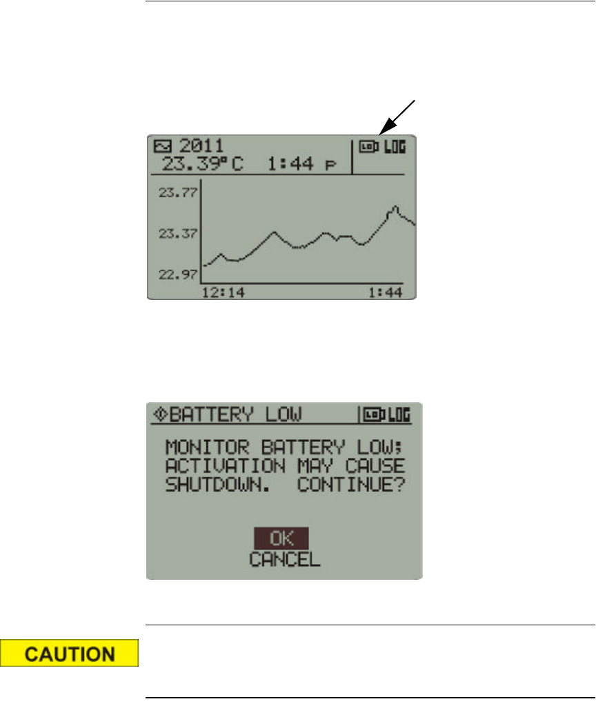
Low Battery Conditions
Low Battery Warning Icon
A low battery condition will be indicated on the front panel display by a
low-battery icon. This is not a “fuel gauge,” i.e., it means that the battery
level has dropped below a set point and should be changed.
Low battery icon
If attempting to activate sensors during a low battery condition, the
following cautionary statement may appear. An attempt to activate sensors
during this condition may result in the monitor shutting down.
Monitor shutdown precaution
Be aware of the following conditions when in a low-battery or no-
battery state. Tracking may be lost as well as the Real Time Clock.
•The non-volatile memory will retain sensor data indefinitely.
•If the monitor is off (with or without the battery) for more than one
hour, the monitor may not be able to resynchronize with the sensors.
•The longer the battery is missing, the greater the risk of the monitor
Real Time Clock losing the correct time. If the RTC time is lost, the
sensor tracking is lost.
4-3
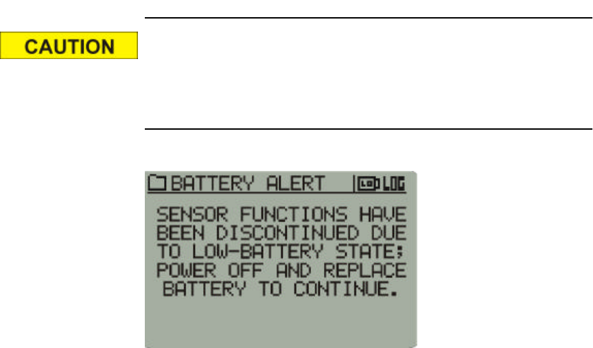
The following display means that the monitor is no longer function-
ing other than displaying the following LCD warning. Data collec-
tion has ceased, but may continue if the battery is replaced quickly
(less than one hour).
1Press the Power button to power down the VitalSense Monitor.
2DO NOT remove the battery until you have a replacement at hand. The
residual power in the battery may be enough to retain time-keeping
information.
3When a replacement is available, install a fresh battery.
4-4 Maintenance
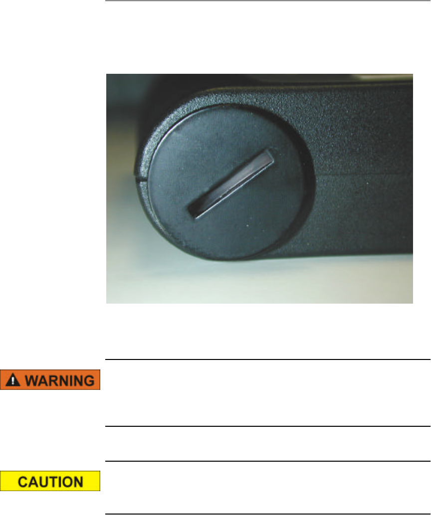
Battery Replacement
1Press the Power button to turn the VitalSense Monitor off.
2The VitalSense Monitor battery is located in the battery compartment,
accessible from the bottom of the monitor as shown below.
Monitor battery compartment
3 Unscrew the battery compartment cover. If necessary, you may use a
coin or screwdriver. Remove the lithium cell.
Do not dispose of lithium batteries in fire or flame. An explosion
may result. Only dispose in accordance with manufacture’s recom-
mendation, or local codes.
When replacing the battery, use only a lithium 3.6 volt AA-size bat-
tery (SAFT LS 14500 or equivalent).
4-5
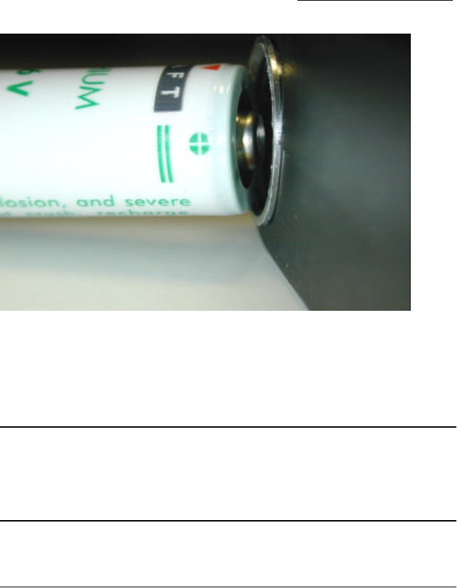
4Replace the battery as shown below, with the positive end inserted first.
Replacement battery inserted
5Replace the battery compartment cover, and finger-tighten. Do not
over-tighten.
6Press the Power button to turn the monitor power on.
NOTE: If sensors are active, VitalSense will reestablish communi-
cation with them and begin data acquisition. This may take a few
minutes.
Calibration
Sensors
Sensors are factory calibrated and do not require user to enter calibration
values.
Monitor
The VitalSense Monitor is calibrated at the factory. An annual factory
calibration and refurbishment schedule is recommended.

4-6 Maintenance
Storage
Although the shelf-life of the monitor battery is extremely long, it is
recommended that the battery be removed if the monitor is to be placed in
storage for more than 180 days.
Cleaning
Cleaning of the VitalSense Monitor can be accomplished by wiping the
surface with a soft, damp cloth. A mild detergent and water can be used to
remove dirt and stains. Do not use abrasives or alcohol. The seals and
display may be damaged. Also see “ Sanitizing VitalSense Components ”
on page-xiii.
5-1
SECTION
5
VS-XHR H
EART
R
ATE
S
ENSOR
Read the material at the end of this section for indications, con-
traindications, cautions, and warnings with regard to the VS-XHR
Heart Rate Sensor and the associated re-charging devices.
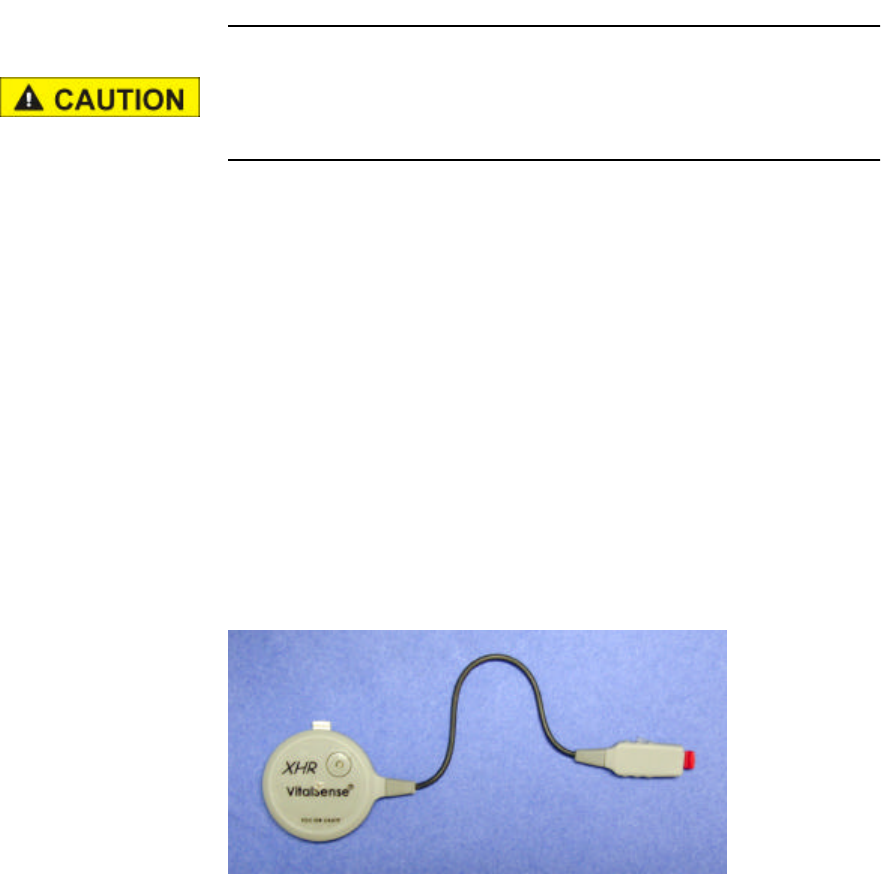
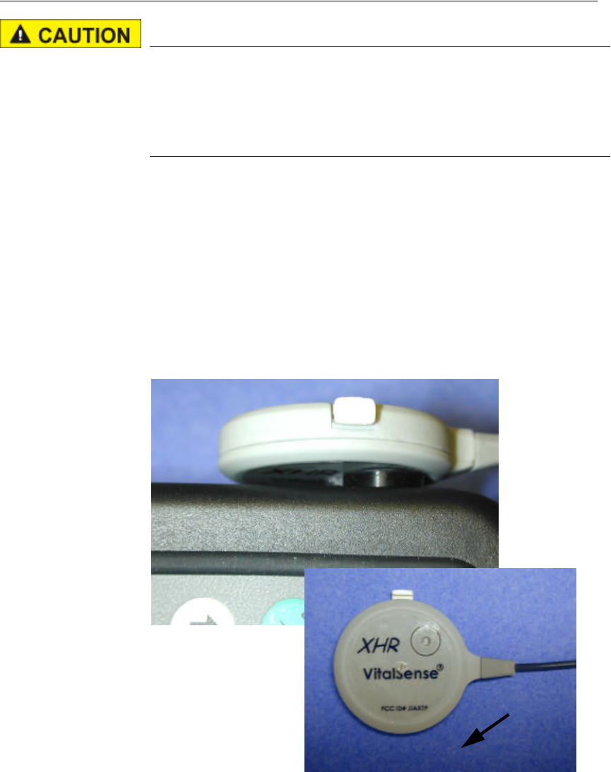
Description VS-XHR is a cardiac monitor sensor, used to detect, measure, and
transmit Heart Rate and Respiration Rate values to the VitalSense
Integrated Physiological Monitoring System (VS-IPMS). VS-XHR
attaches directly to the chest surface using standard disposable ECG
(EKG) electrodes. VS-XHR is powered from its own internal rechargeable
lithium coin cell; there is no external power source. There are no ECG
leads. VS-XHR is not equipped with any alarm function.
Introduction There are four key elements in using the VS-XHR Sensor:
•Charge the batteries
•Activate the sensor
•Attach the sensor
•Reset the sensor after use
5-2 VS-XHR Sensor
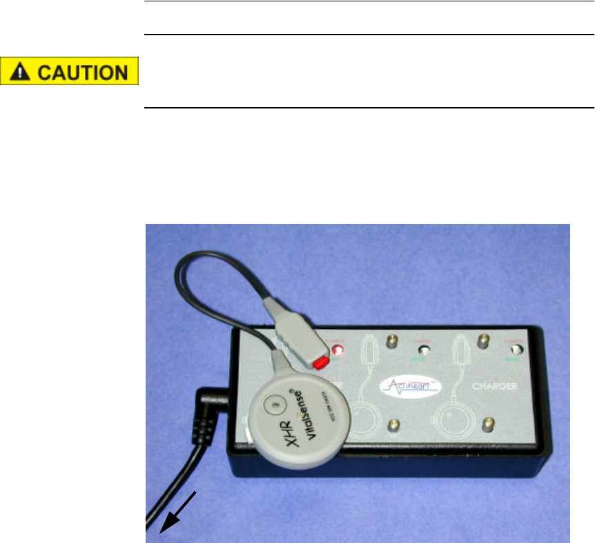
Charging the VS-XHR Sensor
Read “ Precautions Prior to Using the Multicharger ” on
page-xxiii.
1Plug the Multicharger power supply into a standard 120 volt outlet.
2Plug the power supply plug into the Multicharger jack (refer to the
illustration below).
To power supply
5-3
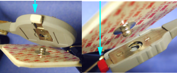
3The VS-XHR Sensor is attached to the metal post on the top of the
Multicharger. Attach the sensor body by pushing the clip inward
toward the center of the device.
4Place over the metal post that is marked with the round sensor symbol,
and release the clip. The tail clip is attached in a likewise manner to the
post marked appropriately with the tail clip symbol. The LED will
illuminate red indicating that the sensor is charging.
Push inward to fasten or to release
The VS-XHR Sensor’s optimum charge-time is 11 hours. Fully
charged, the device will function continuously for four days.
5When the sensor is fully charged, the LED will turn green. Remove the
sensor from the charger and activate.
5-4 VS-XHR Sensor
Precautions Prior to Activating the VS-XHR Sensor
Read before activating sensor!
Become familiar with the section “ Notices to Practitioners and Subjects ”
on page-vii. It contains important information you need to know prior to
activating and using the VS-XHR Heart Rate Sensor.
Activation
Activation is nearly identical to the Capsule and Dermal sensors. The
primary difference is the VS-XHR Sensor can be re-activated and re-used.
1 The process of activation begins by turning on the VitalSense Monitor
(for an illustration, see “ Activating Sensors Using the VitalSense
Monitor ” on page2-7). Press the Power button for approximately ½-
second.
2Press the Activate Sensor button on the monitor.
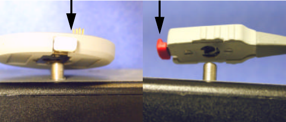
3Follow the directions on the display. Place the VS-XHR Sensor lens
against the Activation Port. The lens is marked with a black circle as
shown below.
4Press Activate Sensor again.
5Follow the directions on the display just as with the VitalSense Capsule
and Dermal sensors.
Lens

5-5
Resetting the VitalSense XHR
Unlike the Capsule Sensor and the Dermal Sensor, the VS- XHR Sensor
can be re-used.
The following procedure is very similar to the charging procedure except
the VS-XHR Sensor is left on the multi-charger for only a short time.
1Connect the multi-charger to the power supply as described on
page5-2.
2Clip the VS-XHR on the multi-charger as indicated by the diagram on
the top of the multi-charger.
3Leave the VS-XHR Sensor on the unit for two (2) minutes to erase the
previous data and reset the unit for activation and re-use.
C
HAPTER
5
5-6 VS-XHR Sensor
XHR Sensor Placement
NOTE: Before collecting data, make sure the battery is fully
charged.
ECG Electrode Positioning
Accurate lead positioning is important if accurate data are to be acquired.
The following is a brief description of where the leads should be placed.
For additional information on lead placement and cardiophysiology, see “
The Heart ” on pageB-1.
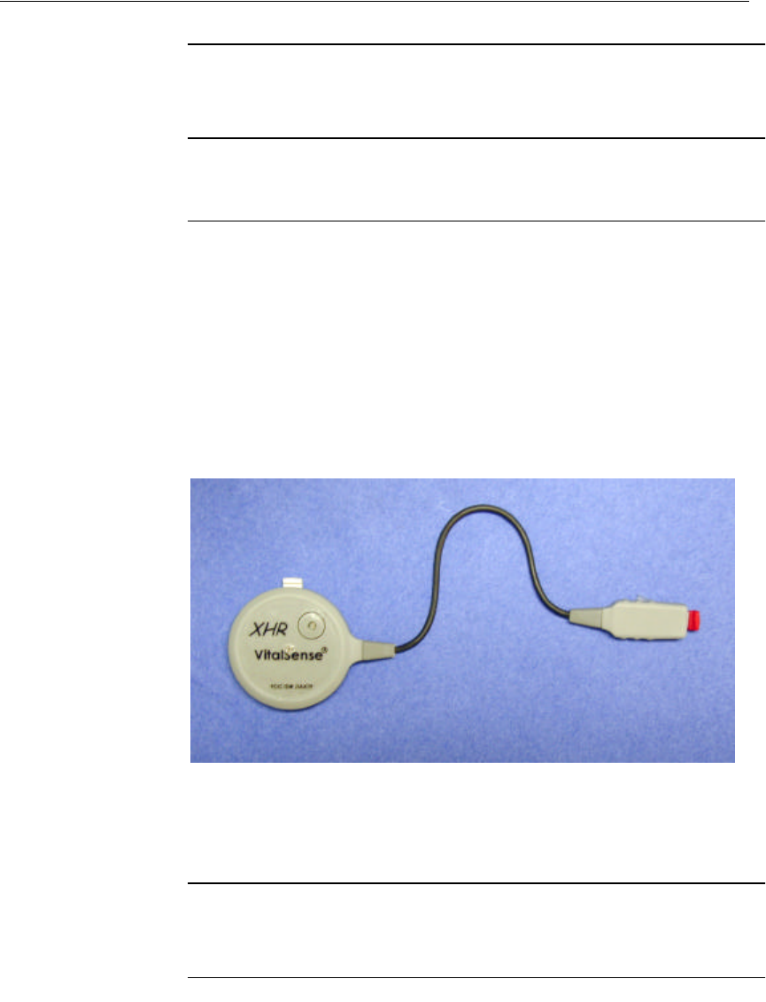
The VS-XHR Sensor consists of the larger, round, main sensor, and a lead
to the positive electrode lead that is typically worn on the left side of the
chest. Both sensor leads have snap-clips which will affix to the ECG
electrode’s male snap. Each electrode must be placed in a specific
location.
Main sensor Tail (Left) lead
The main sensor and left lead should be placed as shown above, with the
snap-clip on top of the main sensor, and the logos on both devices right-
side up.
NOTE: A variety of electrodes have been successfully used with the
XHR Sensor. See “ ECG (EKG) Electrodes ” on pageA-6.
5-7
Attachment to ECG Electrodes
XHR Heart Rate Sensor is attached to the ECG electrodes as follows:
1The Main Sensor body is attached to the mail snap portion of the ECG
electrode. Attach the sensor body to the electrode by pushing the clip
inward toward the center of the device as shown below.
2Place the sensor body over the ECG electrode male snap and release the
clip as shown below.
3The tail of the sensor is attached in a likewise manner.
Push inward to fasten or to release
Release
To remove either end of the sensor, press inward on the clip and remove
the device.
Site Preparation
1Both sites must be free of hair. Shaving the sites not only allows the
electrodes to be affixed more securely, but removing the hair will allow
better contact and less resistance.
2Clean both sites with alcohol. This will remove excessive skin oils and
allow better contact of the electrodes.
3Peel away the ECG sensor’s protective layer and affix the electrodes
per the following instructions.
5-8 VS-XHR Sensor
Lead
I
Electrode Site
In addition to acquiring a good ECG signal, the Lead I position may also
be used if the subject has excessive adipose tissue, injury, or pendulous
breasts. It may be necessary to affix the electrodes as shown below.
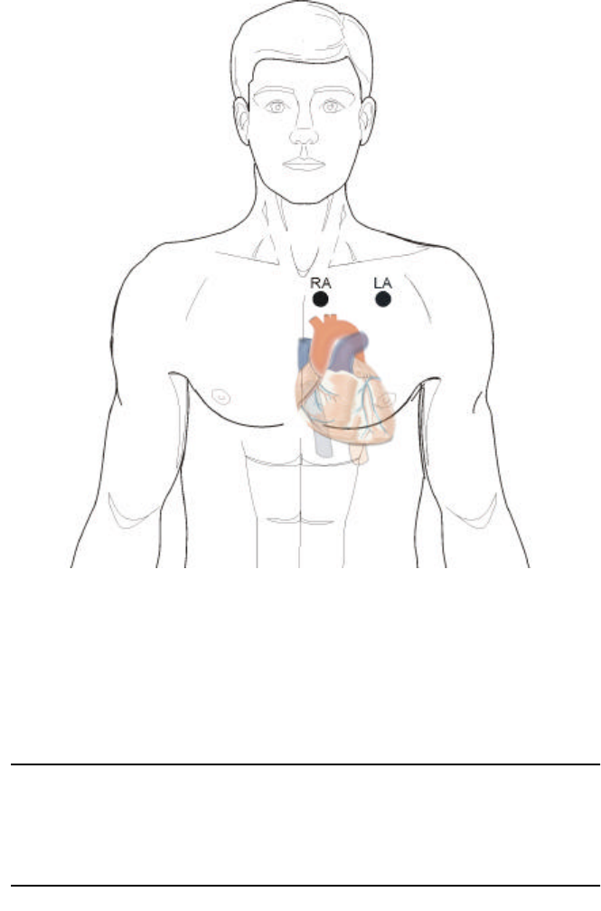
•The main sensor (RA) electrode must be placed near the center of the
sternum centered on the arms.
•The left lead (LA) must be placed the length of the connecting wire,
along the mid-clavicular line.
Lead I
Connecting the XHR Sensor to Electrodes
1Press to open the snap-clips on the XHR Sensor, and clip on to the main
sensor electrode pad.
2Repeat the process with the left lead and the remaining electrode pad
stud connector.
NOTE: The electrode pads should be replaced every three days to
prevent irritation, inflammation, or infection. The site of the elec-
trodes should be varied slightly.
5-9
Lead
II
Electrode Site
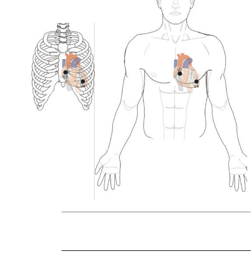
The Lead II site may be used if the Lead I site provides a low signal, or
perhaps the subject may require an alternate site.
The main sensor electrode pad should be placed as shown below at
location V2. V2 is to the immediate left of the sternum at the fourth
intercostal space (the space between the ribs). Ribs are counted from top
to bottom.
The left lead must be placed as shown below. V4 is located at the 5th
intercostal space in the mid-clavicular line.
Lead II
NOTE: Do to variances in the human body, it is recommended that
a brief session be recorded and downloaded to ensure the electrode
placement is optimum.
1
2
3
4
5

5-10 VS-XHR Sensor
VitalSense XHR Sensor Specification
Intended Use
VS-XHR Sensor is intended to be used as a heart rate and/or respiration
rate monitor, in conjunction with the VitalSense Integrated Physiological
Monitoring System. VS-XHR Sensor is not an ECG monitor. VS-XHR
Sensor is not equipped with alarms to signal tachycardia or any other
cardiac arrhythmias.
Physical Attributes:Sensor
ECG Electrode Types
VS-XHR Sensor is considered a two-lead ECG detection sensor. It uses a
modified Lead I or Lead II connection. See “ Site Preparation ” on
page5-7 for a description of the preferred lead placement sites.
Parameter Value Condition/Note
Size 195 mm length, overall 38 mm diameter,
12.5 mm tail clip Outer dimensions
Weight 12 grams With no ECG
electrodes attached
Case material Polycarbonate/ABS Flammability rating
94V-0
Attachment clip
material Stainless steel
Attachment type Adult ECG snap
Battery type 3.0 volt lithium rechargeable Not user replaceable
Indicators Green LED Coincident with heart
beat
Lead Type Sensor Body Sensor Tail
Lead I White (RA) Red (LA)
Lead II White (RA) Red (LL)

5-11
Physical Attributes: Reader/Charger
Physical Attributes: Multicharger
Environmental Attributes: Sensor
Environmental Attributes: Reader/Charger and
Multicharger
Parameter Value Condition/Note
Size TBD Outer dimension
Weight TBD
Case material ABS
Indicators Red LED Flammability
rating 94V-HB
Parameter Value Condition/Note
Size TBD Outer dimension
Weight TBD
Case material ABS Flammability rating 94V-HB
Charging pin material Stainless steel
Number of Charging Ports 3Simultaneous
Indicators Green/Red LED One for each charging port
Overcharge protection Automatic Each charging port independent
Parameter Value Condition/Note
Moisture protection Splash proof Meets IP-52 per NEMA 250
Storage temperature -20 to 50 °C 5-95% humidity
Operating temperature range 0 to 45 °C
Shock 1 meter to tiled concrete floor,
any face
Transportation temperature -20 to 50 °C 5-95% humidity
Parameter Value Condition/Note
Moisture protection Not water resistant
Storage temperature -20 to 50 °C 5-95% humidity
Operating temperature 0 to 40 °C
Shock 1 meter to tiled concrete floor,
any face
Transportation temperature -20 to 50°C 5-95% humidity

5-12 VS-XHR Sensor
Functional and performance specifications
NOTE: When AAMI-EC13 is referenced, it refers to 2002 version.
Parameter Value Condition/Note
Reception range 1 to 2 meters From sensor to monitor
Heart Rate sensing range 16 to 255 BPM Averaged on 15-second interval
Heart Rate resolution ±1 BPM
Sensing interval 15 seconds Fixed
Sensor battery life 4 days Typical
Sensor battery recharge time 11 hours Typical
Calibration None required
Sampling rate 256 samples/second
Analog bandwidth 3.5 Hz to 100 Hz
Input protection per AAMI-EC13-
4.1.2.1(a) Not resistant VS-XHR may be damaged or its accuracy
may be affected by use of electrosurgery or
electrocautery equipment
Open lead detection current per
AAMI-EC13-4.1.2.1(b) Maximum voltage 900 µV
Maximum current 990 nA
20 millisecond pulse
Tall T-wave rejection per AAMI-
EC13-4.1.2.1(c) Meets requirements for 0.5 mV,
0.75 mV, 0.875 mV, 1.0 mV, 1.2
mV, and 1.4 mV
AAMI test waveform definition
HR averaging method per AAMI-
EC13-4.1.2.1(d) Averages ensemble of last 16
IBIs Rejects any IBI values greater than 37.5%
from ensemble average
Irregular rhythm response See table below
Response to change in HR per
AAMI-EC13-4.1.2.1(f) 80 BPM to 120 BPM: 15 sec
80 BPM to 40 BPM: 15 sec
Logged data
Alarms per AAMI-EC13-4.1.2.1
(g), (i), (j), (q) Do not apply VS-XHR does not provide any alarm
functions
RF frequency and modulation per
AAMI-EC13-4.1.2.1(1)-1) 40.68 MHz ISM band FSK
modulation
Special skin preparation per AAMI-
EC-13-4.1.2.1(1)-2) Preparation per instruction
manual
Detached leads, transmitter battery
depletion per AAMI-EC-13-
4.1.2.1(1)-3)
Message displayed on monitor Press any key to eliminate message
Out-of-range per AAMI-EC13-
4.1.2.1(1)-3) Asterisk shown next to sensor ID
on Data Views
Electrode polarization per AAMI-
EC13-4.1.2.1(o) See for recommended electrodes
Common mode rejection Does not apply VS-XHR directly attached to chest surface
Input impedance 5 MΩ
Input range (ac) 15 mV peak-to-peak
Input range (dc) +5 V to -0.9 mV
Defibrillator use See warnings
Leakage current per AAMI-EC13-
4.2.3 and 4.2.5 TBD
QRS detection voltage range per
AAMI-EC13-4.2.6.1 0.5 mV Waveform defined in AAMI-EC13 Fig 6
QRS detection time base range per
AAMI-EC13-4.2.6.2 TBD

5-13
Irregular Rhythm Responses
Per AAMI EC13-5.1.2.1(e)
Regulatory Standards
VitalSense-XHR Sensor will be tested according to the following
standards:
ECG Complex Waveform VitalSense-XHR
Response
(Avg BPM)
Expected
(BMP)
3a: Ventricular bigeminy AAMI 3a 83 80
3b: Slow alternating ventricular
bigeminy AAMI 3b 58 60
3c: Rapid alternating ventricular
bigeminy AAMI 3c 58 120
3d: Bidirectional systoles AAMI 3d 123 90
Test Standard Description VS-
XHR
Sensor
Multi-
charger Reader/
Charger
IEC60601-1 Medical Electrical Equipment - Part 1:
General Requirements for Safety 3
IEC60601-1-2 Medical Electrical Equipment - Part 1-2:
General Requirements for Safety - Collateral
Standard: Electromagnetic Compatibility -
Requirements and Tests
3 3 3
IEC60950-1 Information Technology Equipment - Safety -
Part 1: General Requirements 3 3
47 CFR 15.229 Intentional Radiator Permissive Change 3
ASTM/AAMI-
ESI:1993 Safe current limits for electromedical
apparatus 3
AAMI-EC13:2002 Cardiac Monitors, Heart Rate Meters, and
Alarms 3

5-14 VS-XHR Sensor
ECG (EKG) Electrodes
(See footnotes 1, 2, and 3)
A number of electrodes have been used successfully with the Actiheart
Logger.
Notes:
1 All listed electrodes are Ag/Ag/Cl formulation
2 All listed electrodes are single-use only. Do not re-use electrodes.
3 All listed electrodes contain no latex and no PVC.
4 Discontinue use if irritation develops at any time.
5 For measurement of HR during rigorous exercise, 3M Red Dot 2560
electrode is recommended.
Electrode type and
part number5Subject
age
Recommended
term of use4Contact
type Pad type Shape, size Pkg
Qty
3M Red Dot
2560
Adult 1-5 days Sticky gel Foam Rectangular
38mm x 40 mm
50
Lead-Lok Skintact
Elite FS-VB01
Adult 1-5 days Wet gel Foam Oval
50mm x 35 mm
30
Quinton Quik-Trace
00310-001
Adult 1-3 days Solid gel Clear
perforated tape Round
43 mm
30
Lead-Lok Skintact
CT601
Adult 24 hours maximum Solid gel Clear tape Round
50 mm
30
Lead-Lok
P-7
Pediatric,
infant
1-2 days Solid gel Foam Teardrop
22 mm
3
3M Red Dot
2248
Pediatric 1-2 days Solid gel Surgical tape Round
44 mm
25
3M Red Dot
2258
Infant 1-2 days Solid gel Soft cloth Round
32 mm
3

A-1
AP P ENDIX
A
C
HAPTER
1
F
REQUENTLY
A
SKED
Q
UESTIONS
What is Standard Mode?
Standard Mode is the default mode in all VitalSense Monitors. When
operated in Standard Mode, a monitor receives data from sensors activated
by that monitor and excludes transmissions from other sensors not
activated by that monitor.
The model number of the Standard Mode monitors begin with STD. The
model number can be found on the back of the device.
The alternative to Standard Mode is Medic Mode™, an option installed in
some VitalSense Monitors.
How long will the battery last in Standard Mode?
With 10 sensors on line (maximum), the disposable lithium cell will last
approximately 10 days receiving, and 20 days standby.
What is Medic Mode
™
?
Medic Mode allows the monitor to receive transmissions from all active
sensors within range, without regard to which monitor activated them. It
also allows more than 10 sensors to be activated with a single monitor.
This feature comes at a cost in that sensors activated while in Medic Mode
cannot be tracked if the monitor is switched back to Standard Mode.
However, switching from Standard to Medic Mode will not, in most cases,
cause the monitor to stop tracking sensors when switching from Medic
Mode back to Standard Mode. The monitor will attempt to re-synchronize
with the sensors. Re-synchronization is not guaranteed, therefore
switching to Medic Mode from Standard Mode is not recommended if
data loss cannot be tolerated.
Another key difference is that in Medic Mode, sensor data are time-
stamped with the time the data are received. Standard Mode sensor data
are time-stamped with the actual time of measurement. The difference
between those two times may vary from 3 to 12 seconds.

A-2 Frequently Asked Questions
How long will the battery last in Medic Mode
™
?
If the monitor is left on continuously in Medic Mode, the disposable
lithium cell will last approximately 48 hours.
How do I know if my monitor has the Medic Mode
™
option?
Medic Mode will be listed in the Setup Monitor menu. Press the Menu
button on the monitor, then select Setup Monitor.
You can also look at the label on the back of the monitor. The model
number will begin with MED.
Will a common AA alkaline or Ni-Cad battery work in my
monitor?
No! They are the wrong voltage and wrong design. Use only SAFT
LS14500 batteries, available from Mini Mitter.
What should I do if the monitor and sensors are
separated for more than 30 minutes?
First, try bringing the monitor within range of the sensors and wait for 2
minutes. If the monitor does not lock on to the sensors, try turning the
monitor power off, then back on. The monitor will attempt to lock on to
the sensors. If this is not successful, it is likely the sensors have been lost
from tracking. Unfortunately, once a sensor is lost from tracking, it may
not be brought back on line. A lost sensor should be removed from the
tracking list by using “Remove Sensor” on page2-16. This is under the
Sensors Option menu.
Can I still receive data from a “lost” sensor?
Yes, but only if you have Medic Mode, an optional feature of VitalSense.
Details can be found in “Medic Mode” on pageC-1.
Why does the Power button seem to work intermittently?
This is actually by design. The Power button must be held down at least
½-second to power up the monitor. This is to prevent the accidental
operation of the button if jostled in the carrying pouch.
What is the purpose of Lockout Mode?
Lockout Mode is a feature that prevents “idle tampering” of the monitor,
and also reduces the chance of the inadvertent pressing of front panel
buttons during use.
Why may I not have an MRI?
The components within both the Capsule Sensor and Dermal Sensor
contain elements which are incompatible with MRI procedures. You
would risk injury to yourself.
A-3
What if a Capsule Sensor should leak while ingested?
VitalSense ingestible capsule shells are composed of inert plastic and
medical grade plastic adhesive. Each capsule is individually inspected to
insure a complete seal at the factory. VitalSense capsules have been tested
for resistance to moisture, varying pH levels, heat, enzyme reaction,
saline, and alcohol exposure. We know of no condition within the
alimentary tract that could lead to a breach of the capsule seal. However,
as an added precaution, the circuits within the capsule are further coated
with a plastic, water-resistant coating. Finally, the components within the
capsule would pass through the digestive system without noticeable
influence on the subject’s system.
What is the temperature range of the sensors?
See “Specification” on pageD-1.
How is the accuracy of the thermometer sensors
guaranteed?
The accuracy of the sensors is established with a process traceable to the
Nation Bureau of Standards and Technology.
Can a glass bulb thermometer be used to check the
accuracy of my sensors?
No. Glass bulb thermometers are not accurate enough.
How can I check the accuracy of my Capsule Sensors?
You will need a highly temperature-stabilized water bath (better than
0.05 °C stability and accuracy), and a NIST traceable RTD digital
electronic thermometer.
Will the accuracy of the sensors degrade as their
batteries become low?
The sensors will remain accurate for up to 10 days of transmission.
How long will the sensors transmit?
Following activation, approximately 10 days (240 hours). This holds true
following a shelf life of up to one year.
After ingestion, when will the Capsule Sensor begin to
transmit actual core temperature?
Approximately one minute.
What is the best way to administer the Capsule Sensor?
Take it with a glass of water or a soft drink as you would most capsules or
pills.
A-4 Frequently Asked Questions
Are there any dietary restrictions while the Capsule
Sensor is inside me?
None.
Can my Capsule Sensor be re-used?
Capsule Sensors must not be re-used in human applications.
What if a Dermal Patch Sensor causes a rash or
discomfort?
Discomfort may be the result of inadequate hair removal, or placing the
patch on an area of skin that is subject to flexing or stretching. A rash may
be a sign of dermatitis or allergy. Notify your practitioner immediately.
Can the Dermal Patch Sensor be worn in the shower or
bath tub?
Yes. However the VitalSense Monitor must be left outside the shower or
tub.
What is UTC and why is it important?
It stands for Universal Coordinated Time. A complete section has been
devoted to this subject. Turn to “Universal Coordinated Time” on
pageB-1.
How does VitalSense software get installed and
uninstalled?
The VitalSense Application Program is supplied in two distribution
formats: a Microsoft Installer (.msi) package, and as a self-extracting Zip
file. Normally just double-clicking on the MSI version will install the
package. Older versions of Windows may require you to obtain the
installer from the Microsoft website, or use the Zip file. The files will be
installed in C:\Program Files\VitalSense. The MSI package will
automatically create a shortcut on your desktop.
Uninstallation can be done using the Add/Remove Programs feature found
in your control panel. If the installation was done using the Zip package,
simply delete the VitalSense directory and the associated shortcut.
What is the “version” of my firmware?
See “Firmware Version” on page3-21.
The display on the VitalSense Monitor went blank.
Occasionally, to protect itself from electrostatic discharge, the LCD will
shut down. The display will reactivate when a transmission is received, or
when you momentarily press any button.

B-1
AP P ENDIX
B
C
HAPTER
2
U
NIVERSAL
C
OORDINATED
T
IME
If the world were ideal, we would have one time the world over, and all
clocks would read the same. However, because our planet is divided
between day and night, our global structure has generally adopted solar
time. This divides the planet into a series of time zones. Although it makes
it easy to keep time based on daylight, it is very difficult for scientists,
pilots, military, and others to use.
Another complication is the occurrence of Daylight Saving Time in
selected areas. Navigation, exchanging data, astronomy, synchronization
of experiments, and other fields require a single means by which to keep
time.

B-2 Universal Coordinated Time
Another way of keeping time is similar to solar time, called Universal
Time. Within this category are variations. UT1 is a measure of the rotation
angle of the Earth as observed astronomically. Solar time varies slightly.
Because of the Earth’s tides, the earth slows down, wobbles, and
introduces slight variations in measurements. UT1 accounts for these
variations, making it useful for astronomy.
Universal Coordinated Time is the basis for worldwide civil time-keeping.
Timing laboratories around the world contribute to provide the
international standard Universal Coordinated Time (UTC).
NOTE: “UTC” technically does not represent a series of words.
During international discussions, the three letters were agreed upon
as a “symbol” rather than an abbreviation or acronym.
The UTC second is based on the atomic transition of the element cesium
under specific conditions. It is independent of astronomical variations, and
because of its stability is accurate to a nanosecond (1,000,000,000th of a
second) per day.

B-3
UT1 (based on rotation of the Earth) and UTC (based on man-made
instruments) may differ, but never more than 0.9 second. By agreement,
when the difference begins to reach this point, a “leap-second” is
introduced in the UTC. This occurs, on average, every 12 to 18 months.
Universal Coordinated Time may be referred to colloquially (and
historically) as Greenwich Mean Time (GMT). This village lies on the
Greenwich meridian (0° longitude) in England, and for years was the
point of reference for all other time zones. Pacific Standard Time, for
example, is 8 hours behind UTC (UTC-8).
UTC and GMT may also be called Zulu time. This is a common military
term, and is typically shown in 24-hour format, such as 1800Z (6pm).
Finding the Universal Coordinated Time
There are a variety of ways to obtain the UTC. By computer, radio, and
even telephone.
United States Naval Observatory
•Internet
http://tycho.usno.navy.mil
United States Government
•Internet
http://www.time.gov
National Institute of Standards and Technology
•Internet
http://physics.nist.gov/time
•Telephone (delayed by approximately 30 ms because of land line)
(303) 499-7111 in Ft. Collins, Colorado (not toll-free)
(808) 335-4363 in Kauai, Hawaii (not toll-free)
•Radio
WWV - 2.5 MHz, 5 MHz, 10 MHz, 15 MHz, 20 MHz
WWVH - 2.5 MHz, 5 MHz, 10 MHz, 15 MHz
UTC and VitalSense
When collecting time-sensitive data, specifically across time zones, it is
not advisable to change the clock during data collection. Within the
VitalSense Monitor, the real time clock is to be set to UTC. This insures
that the data is universally time-stamped, and can be recognized and
analyzed by scientists throughout the world without regard to time-
conversion or gaps in the data caused by clock changes.

B-4 Universal Coordinated Time
UTC Offset
Since few people operate on UTC on a daily basis, VitalSense needs a
means to display local time. This is done with the UTC offset. Typically
the UTC is entered into the monitor followed by the offset. For example,
the offset for the US Eastern Time Zone is -5 hours. Once the offset is
entered, the local time is correctly displayed.
Conversely, if the Local Time is entered, and the offset is entered, the
Universal Coordinated Time is calculated and displayed.
Daylight Saving Time
Daylight Saving Time within the United States is automatically
compensated for by VitalSense. However, when setting the Time and Date
in the VitalSense Monitor, Local Time should be entered. Once Local
Time is entered, the Daylight Saving compensation box can be checked,
and Vital Sense will, based on the time and date, change the Local Time
automatically if appropriate.
For regions within the United States that do not follow DST, DST may be
disabled and the UTC offset would be used to set the correct local time.
The same is true for local time outside the United States.
Keeping it Simple
There are two methods by which the clock should be set.
Method A
1Check (or uncheck) Daylight Saving Time Auto-set.
2Set the UTC Offset.
3Set the local time.
If the previous three steps are followed, the UTC clock will be set
automatically.
Method B
1Set the UTC time.
2Set the UTC offset.
3Check (or uncheck) Daylight Saving Time Auto-set.
If the previous three steps are followed, the Local Time will be set
automatically.
For more detailed information on setting the VitalSense Monitor clock,
refer to:
•“Adjusting the Time/Date” on page2-20
•“Setting the Monitor Clock” on page3-9

C-1
AP P ENDIX
C
C
HAPTER
3
M
EDIC
M
ODE
Medic Mode Details
Medic Mode puts the VitalSense Monitor in a special configuration to
allow continuous monitoring of unlimited sensors.
•An unlimited number of sensors may be monitored in Medic Mode.
Ten can be monitored in Standard Mode.
•In Medic Mode, a VitalSense Monitor can monitor sensors activated by
another monitor. This is not possible in Standard Mode.
•Although data are logged if enabled, sensors are not tracked.
•Medic Mode can be used to monitor sensors that are still transmitting,
but are no longer in synchronization with their respective VitalSense
Monitor.
•When the VitalSense Monitor is in Medic Mode, a unique icon will
appear on the Data Views display and on the activation sequence
display.
NOTE: Using Medic Mode dramatically reduces the battery life of
the VitalSense Monitor. Expected battery life in continuous use is
approximately 48 hours.
Battery life may be extended by:
•Placing the monitor back in Standard Mode.
•Turning the monitor power off.
•Activating fewer sensors (activation requires the most power of any
VitalSense function).
C-2 Medic Mode
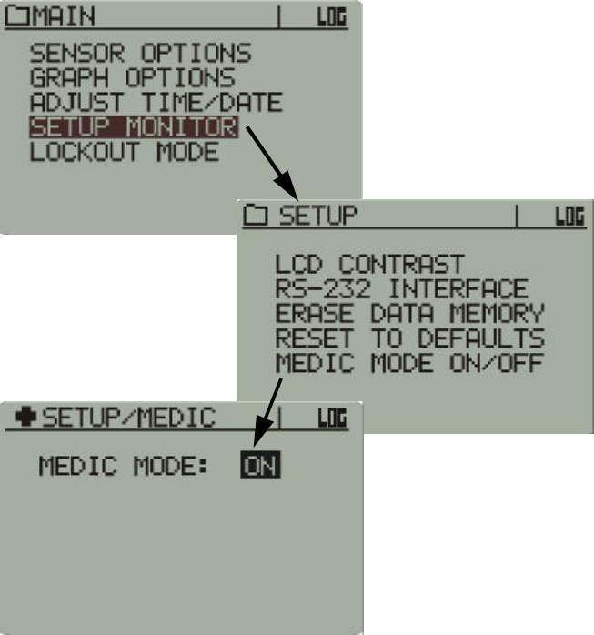
Accessing Medic Mode
Main > Setup > Medic Mode ON/OFF
Medic Mode is primarily for checking sensor performance and
temperature of individual sensors. Other characteristics of Medic Mode
are as follows:
•If sensors have been activated with Medic Mode off and are being
tracked, they will stop being tracked when Medic Mode is turned on.
However, when Medic Mode is turned back off, tracking will resume.
For details on tracking, see “Tracking” on page1-3.
•If sensors are activated with Medic Mode on, they will not be tracked,
but the data will be logged.
•With Medic Mode off, only ten sensors may be tracked and monitored.
With Medic Mode on, an unlimited number of sensors may be activated
and monitored, but none will be tracked.
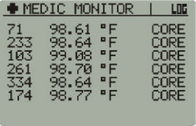
•In Data Views, VitalSense will display a Medic Monitor. Each sensor
detected will be added to a scrolling list. Only six sensors will be
displayed at any one time as the list updates.
C-3
Medic Mode Display
The display is a continuous monitoring of all sensors in the order in which
they are acquired. The list may be scrolled using the arrow buttons.
Medic Mode display
C-4 Medic Mode
D-1
SECTION
D
C
HAPTER
4
S
PECIFICATION
NOTE: Also see “ VitalSense XHR Sensor Specification ” on
page5-10.
Parameter Value Condition/Note
Physical Attributes
(Monitor)
Size 120 x 90 x 25mm Outside dimensions
Weight 200 grams Monitor only
Case material Polycarbonate/ABS
copolymer
Interface Panel Non-permeable membrane
switch
Display Monochrome LCD with
backlight
Physical Attributes
(Capsule Sensor)
Capsule appearance Purple, cylindrical, with
hemispherical ends
Size 8.7 mm O.D. x 23mm
long Total
Weight 1.6 grams
Physical Attributes
(Dermal Patch Sensor)
Patch appearance Off-white, circular, flat
Size 57.2 mm O.D. x 6.0 mm
thick Total
Weight 7.5 grams

D-2 Specification
1 This specification has been verified in accordance with ASTM-E1112-00.
*Operation and storage outside the stated temperature and humidity range may degrade performance.
**Subjecting to shock outside the stated range may degrade performance.
Parameter Value Condition/Note
Functional Attributes
Temperature sensing range 25 °C to 50 °C Ingestible capsule
-20 °C to 60 °C Dermal patch
Temperature sensing accuracy ±0.10 °C 32 °C to 42 °C
(Guaranteed1)
±0.05 °C 32 °C to 42 °C
(Typical)
±0.25 °C -20 °C to 32 °C
(Guaranteed)
±0.25 °C 42 °C to 60 °C
(Guaranteed)
Temperature display resolution ±0.01 °C
Display update rate 15 seconds Average
Monitor battery life 10 days (240 hours) with
10 sensors on line, plus 20
days standby
Battery life increases with
fewer sensors on line
Sensor battery life 1 year storage plus 10
days active transmission Capsule and patch
Calibration None required
Number of co-active sensors One to ten Per monitor
Sensor identification Automatic tracking
Crosstalk Not allowed
Maximum logging time 6 days
10 days
10 sensors
5 sensors
Environmental Attributes
Moisture protection IEC529-IP52
NEMA 250-5.3
Monitor and sensors
Storage temperature* -20 to 50 °C @ 5-95% humidity
Monitor and sensors
Operating temperature* 0 to 40 °C Monitor
Shock** 1 meter drop to tiled
concrete floor Monitor
Transportation Environment
Attributes
Moisture protection IEC529-IP52
NEMA 250-5.3
Monitor and sensors
Storage temperature -20 to 50 °C @ 5-95% humidity
Monitor
Shock 1 meter drop to tiled
concrete floor Monitor

D-3
Parameter Value Condition/Note
Radio Frequency Attributes
Transmission range Maximum 1 meter
Maximum 2 meters
Capsule sensor
Dermal Patch
Software/PC Attributes
Software features Data transfer, ASCII
conversion
Compatibility Windows® ‘98, 2000, XP,
Millennium, or Windows
NT 4.0 SP 6
Communications interface RS-232 cable Custom, water protected

D-4 Specification
Agency Standards Met
Limitations
The VitalSense ingestible capsule thermometer is a Class II Medical
Device according to 21 CFR 882.1845 and is classified as a Surface
Contacting Device according to ISO 10993-1. The capsule is intended to
be used in contact with the mucosal membrane (alimentary tract) only.
The VitalSense ingestible capsule thermometer must not be used in any
situation where the mucosal membrane is already breached by surgery or
trauma. The VitalSense ingestible capsule thermometer is not intended to
be used as an implant. For additional information, contact Mini Mitter
Company, Inc.
Medical Device
VitalSense system is cleared by the United States Food and Drug
Administration for marketing as a Class II medical device.
Clinical Thermometer
VitalSenses meets ASTM-E1112-00, Standard Specification for
Electronic Thermometer for Intermittent Determination of Patient
Temperature.
(For those VitalSense System owners needing “Determination of Accuracy” documentation related to
this specification, please contact Mini Mitter.)
Radio Emissions
VitalSense meets CFR Title 47, Part 15, Subpart C. FCC listing code is
JIAXTP1.
Human Safety
This device is classified as Type CF protection against electrical shock.
The VitalSense Monitor conforms to IEC 60601-1 (UL 2601-1).
Water Resistance
VitalSense monitor meets IEC 529-IP52, and NEMA 250-5.
Safety Labeling and Terminology
Instruction manual conforms to ANSI Z535.4-2002
♥

Index - 1
A
Activation of Sensors
See Sensors
Administration
Capsule Sensor,2-10
Dermal Patch Sensor,2-10
Astrisk
meaning of in Data Views,2-33
Attributes
Environmental,D-2
Functional,D-2
Physical,D-1
Radio Frequency,D-3
Software/PC,D-3
Transportation Environment,D-2
B
Battery
Alert,4-3
Alkaline or NiCad,A-2
Cautions,4-1, 4-3, 4-4
Installation,4-5
Life,A-1
Low battery indication,2-13, 2-14
Requirements and Specification,4-1
Storage,4-6
Baud Rate,2-26, 3-7
C
Calibration,1-3, 4-5
Capsule Sensor
Comparative Size,2-6
Precautions,2-6
Classifications
Class B digital device,i-xiv, D-4
Class II Medical Device,i-xvii
Type CF,i-xiv, D-4
Clear Memory,3-10
Clock
Manually Set Monitor Time,3-10
Read Monitor Clock,3-10
Set Monitor to PC TIme,3-10
Setting from Application Software,3-9
Setting from monitor front panel,2-20
COM Port,3-7
Communication errors
COM Port,3-24
General,3-25
Connecting VitalSense Hardware,3-4
Connector
9-pin serial DB9,3-4, 3-5
USB,3-4
D
Data Collection Summary,3-17
Data Logging
On/Off,2-18, 3-14
Data Views,2-32
Graph,2-32
List,2-32
Daylight Saving Time,2-4, B-4
Auto-Set,2-23
Dermal Patch Sensor
Application,2-5
Description,2-5
Precautions,2-5, 5-4
Protective layer,2-5
Diagnostic information,3-25
E
ECG Electrodes
Electrode Compatability,5-14
Lead II Site,5-9
Site Preparation,5-7
Electromagnetic Interference (EMI),i-vii
Avoidance,i-viii
Effects on VitalSense,i-vii
Practitioner Advisories,i-vii
Electrostatic Discharge Effects
On monitor,i-x, A-4
Susceptability levels,i-x
Emissions,i-vii, i-xi, D-4
Aircraft (FAA),i-xi
Interference,i-xi
Radio (FCC),i-xi
Environments
EMI,i-ix
F
Factory default
Resetting,2-29
Time,2-22
FCC listing code,D-4
Index
Index - 2
File-type
,exe,3-3
.msi,3-3
.txt,3-16, 3-19
.vsb,3-16
.xls,3-19
Firmware,1-3
Finding version from PC,3-21
Flow Control,2-26, 3-7
Font sizes,3-2
Frequency
Sensor,i-vii
Frequently Asked Questions,A-1
G
Getting Started,1-2
I
Icon definitions,2-14
Implantation
Limitations,i-xvii
L
Labeling Sensors,2-8
Lockout Mode,A-2
Lockout mode,2-31
deactivating,2-31
Low Battery
Conditions,4-2
Low battery indicator,2-13, 2-14
M
Medic Mode,1-2
Frequently Asked Questions,A-1
Operation,C-1
Menu
Adjusting the Time/Date,2-20
Graph Options
Length (X),2-19
Lockout Mode,2-31
Sensor Options
Activate Sensor,2-15
Logging ON/OFF,2-18
Remove Sensor,2-16
Sensor Units of Measure,2-18
Setup Monitor
Erase Data Memory,2-27
LCD contrast,2-25
Reset to defaults,2-29
RS-232 interface,2-26
Monitor Operation
See VitalSense Monitor
Monitoring Data in Real Time,3-20
MRI (magnetic resonance imaging)
warning,i-vii, i-xv, i-xviii, i-xxi, A-2
N
New Subject,3-11
Notices to Practitioners and Subjects,i-vii
O
Options
Application Program,3-21
Out-of-Range Conditions,2-33
P
PC Preparation,3-2
Power button
Intermittent,A-2
R
Radio and Television Frequencies,i-ix
Radio Frequency Environments,i-ix
Read Data,3-16
Real Time Monitoring,3-20
Reporting rate,1-1
Restrictions,i-xi
RS-232,3-1, 3-8
Errors,3-26
Establishing communications,3-24
Interface,2-26
S
Safety Labels and Terminology,i-vi
Sanitizing VitalSense Components,i-xiii
Sensor Summary Table,3-14
Sensors,1-2
Activate sensor,2-15
Activation procedure,2-7
Battery life,1-2
Capsule Sensor Adverse Reactions,i-xix
Capsule Sensor Contraindications,i-xvii
Capsule Sensor Description,i-xvii
Capsule Sensor Indications,i-xvii
Capsule Sensor Precautions,i-xviii, 2-6
Capsule Sensor Warnings,i-xviii
Dermal Patch Adverse Reactions,i-xvi, i-xxii
Dermal Patch Contraindications,i-xv, i-xxi
Dermal Patch Description,i-xv, i-xx
Dermal Patch Indications,i-xv, i-xx
Dermal Patch Precautions,i-xvi, i-xxii
Dermal Patch Sensor precautions,2-5
Duplicate sensor,2-12
Index - 3
Failure to activate,2-11
Frequently Asked Questions,A-2
Labeling,2-9
Limitations,i-xvii
Logging On/Off,2-18
Sensor activation,1-2, 2-7
Specification,D-1
Tracking,1-3
Travel on aircraft,i-xii
Serial COM port
9-pin DB9,3-4
Setup,3-7
USB,3-4
Setting the Time and Date,2-21
Shipping Address,i-v
Specification,D-1
Standard Mode
Explanation,A-1
Standards,D-4
21 CFR 882.1845,i-xvii
21 CFR Part 15.229,i-ix
ANSI Z535.4-2002,D-4
ASTM-E1112-00,i-xii, D-2, D-4
IEC 529-IP52,D-4
IEC 60601-1,i-ix, D-4
IEC529-IP52,D-2
ISO 10993-1,i-xvii
MIL-STD 461E,i-ix
MIL-STD 462E,i-ix
NEMA 250-5,D-2, D-4
Subject Information,3-10, 3-11
T
Technical Support,i-v
Time and Date,2-4
Tracking,1-3
Travel by Commercial Aircraft,i-xii
U
Universal Coordinated Time (UTC),2-4, B-1
data saved in,2-24
Display option,3-21
Finding the UTC,B-3
GMT,B-3
UT1,B-3
UTC Offset,2-24, B-4
Zulu,B-3
USB
Adapter Installation,3-26
Description,3-5
USB Adapter,3-26
UTC (Universal Coordinated Time) See Universal
Coordinated Time (UTC)
V
VitalSense Application Program,3-1
Data Collection Summary,3-17
Finding Firmware Version,3-21
Functions,3-1
Generate Report,3-18
Installation,3-2, 3-3
Monitoring in Real Time,3-20
Options,3-21
Preferred Settings,3-2
Requirements,3-2
Retrieving Data,3-16
Sensor Activation Table,3-14
Sensor Options,3-14
Subject Information Wizard,3-11
Upgrading Firmware,3-22
VitalSense Components,1-1
VitalSense Monitor
Cleaning,4-6
Clock Setup,3-9
Configuration,2-4, 3-7, 3-8
Description,1-2, 2-1
Display Details,2-13
Display icons,2-13, 2-14
Front Panel,2-1
Front Panel Controls,2-2
Initial Setup,2-4, 3-7
Maintenance,4-1
Manually Set Monitor Time,3-10
Operation from Application Program,3-1
Operation from front panel,2-1
Read Monitor Clock,3-10
Set Monitor to PC Time,3-10
Setup,3-8
Storage,4-6
Three requirements at setup,2-4
VitalSense Sensors
See Sensors
VitalSense Software
See VitalSense Application Program
VitalSense System
Autoclaving,i-xiii
Calibration,1-3
Components,1-1
Console window,3-25
Frequency,i-vii
Hardware installation,3-5
Introduction,1-1
Modification of,i-xii
Precautions,i-xv
Sanitizing,i-xiii
Index - 4
W
Warnings
Capsule Sensor,i-xviii
Definitions,i-vi
Dermal Patch Sensor,i-xv, i-xxi
Lithium battery disposal,4-1, 4-4
Low battery,4-2
Low battery icon,4-2
MRI (magnetic resonance imaging),i-vii
Weight,D-1
X
XHR Heart Rate Sensor,5-1
Charging the battery,5-2
Lens location,5-4
Sensor Activation,5-4