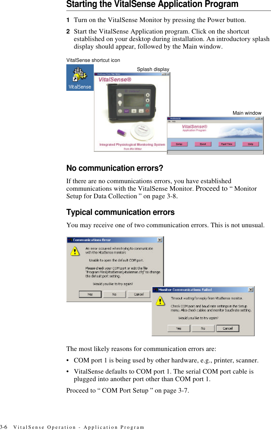
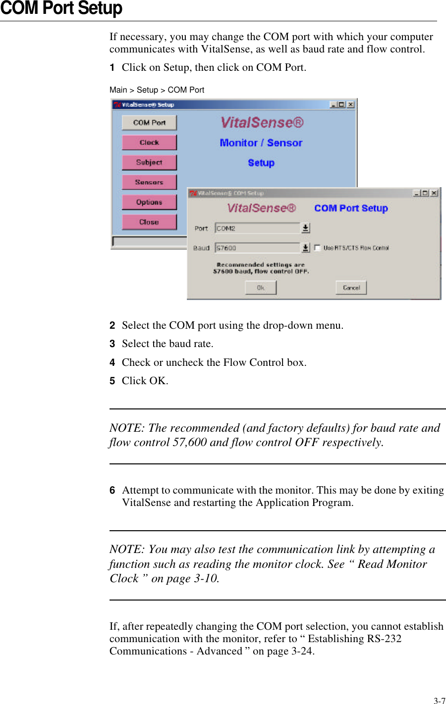
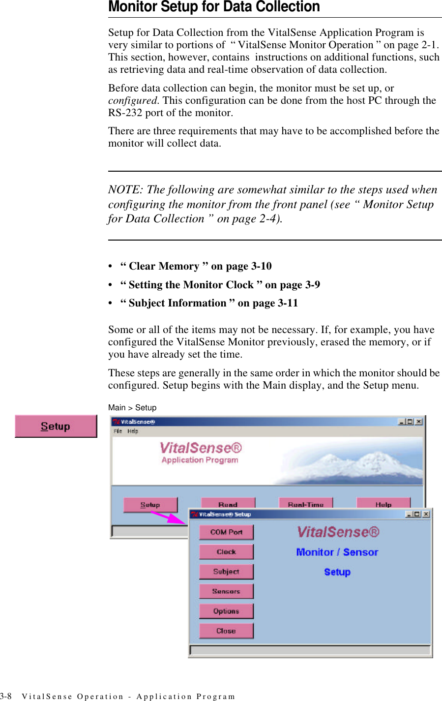
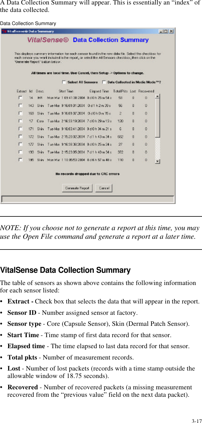
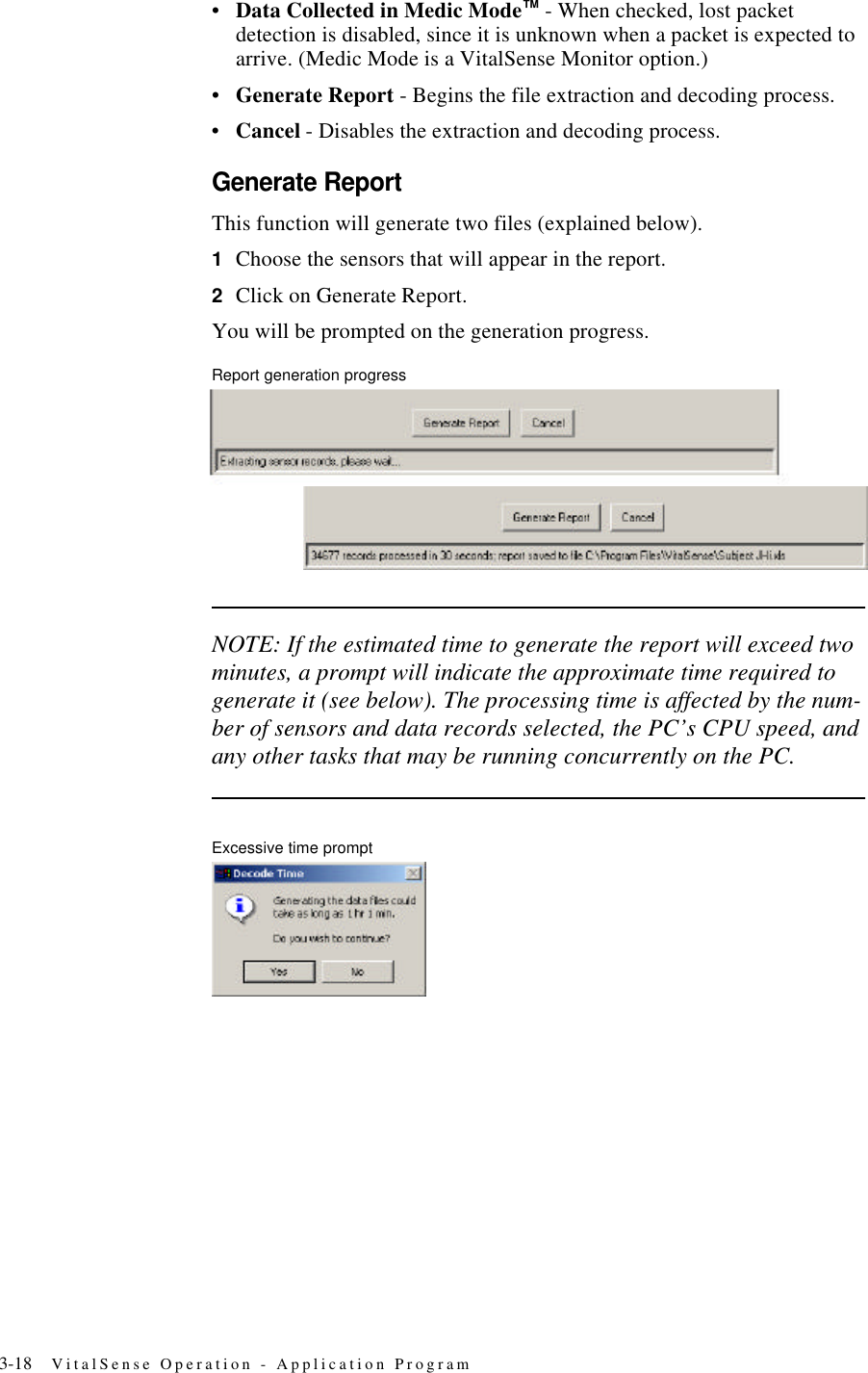
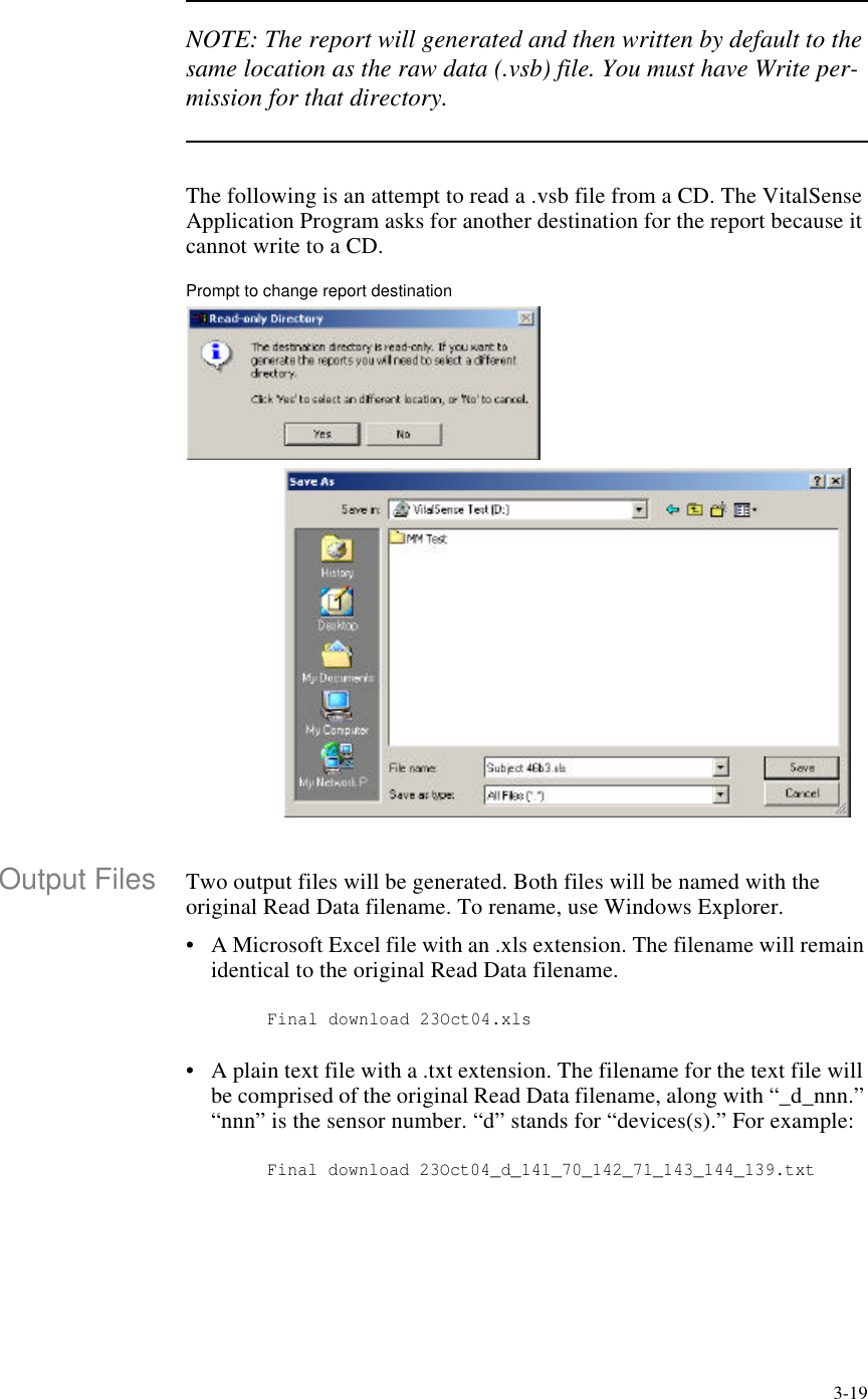
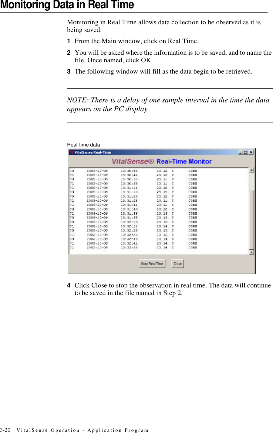
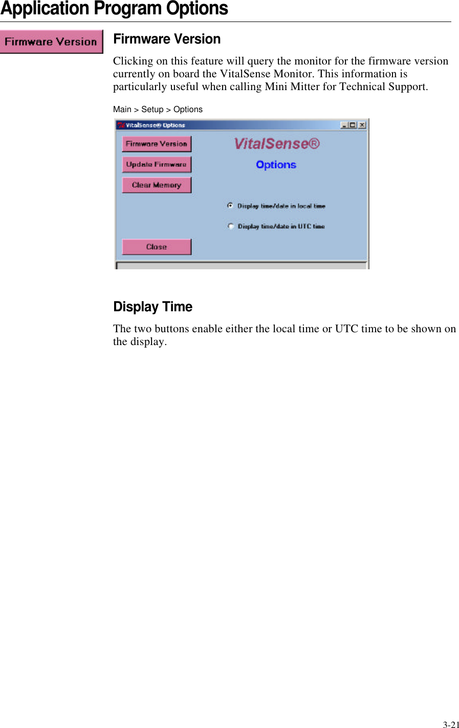
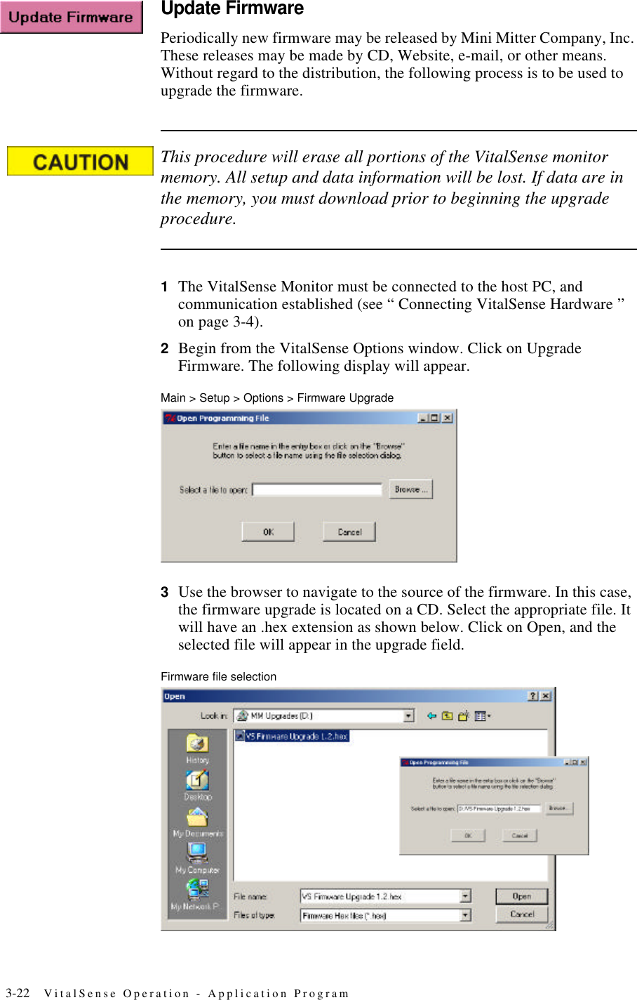
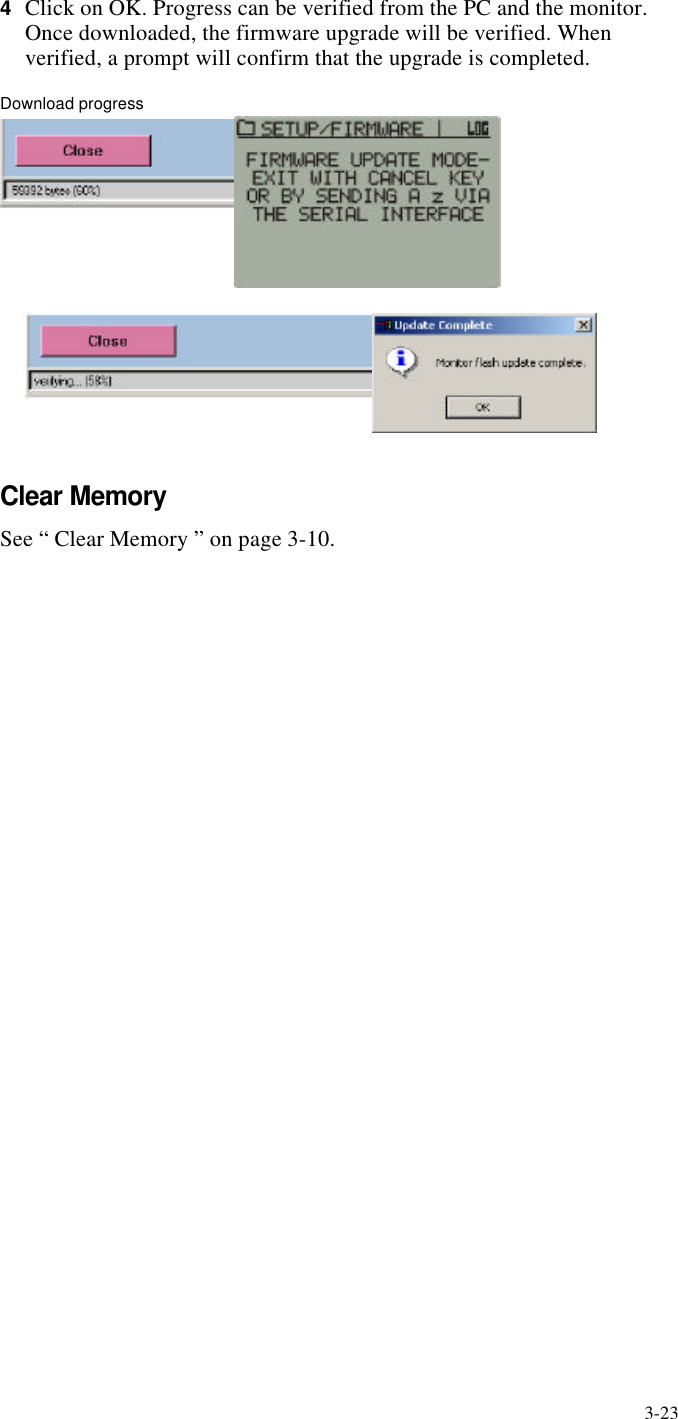
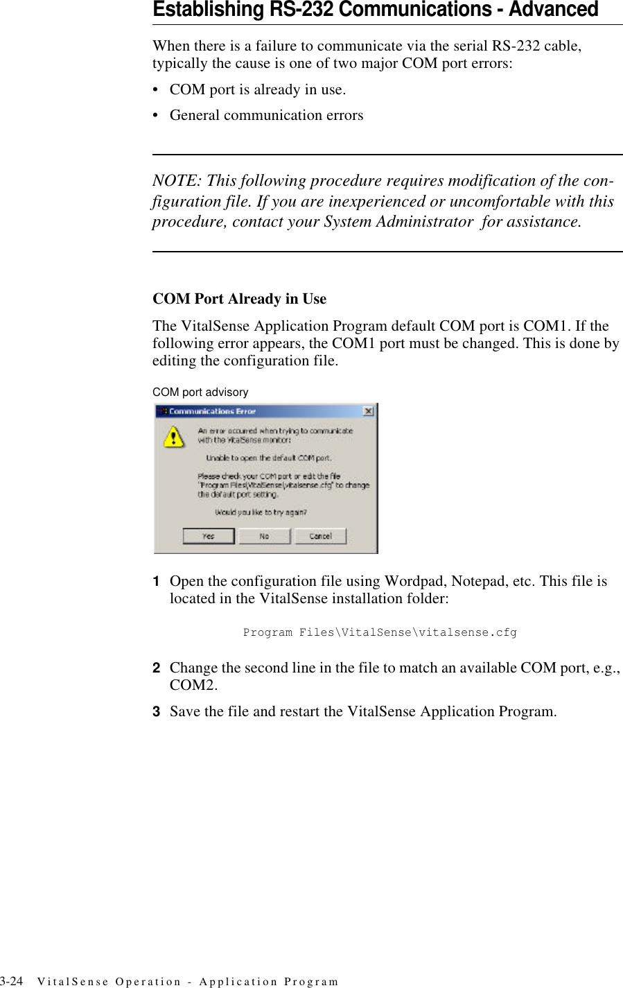
Mini Mitter XTP1 Integrated Physiological Monitoring System User Manual Tinman Book
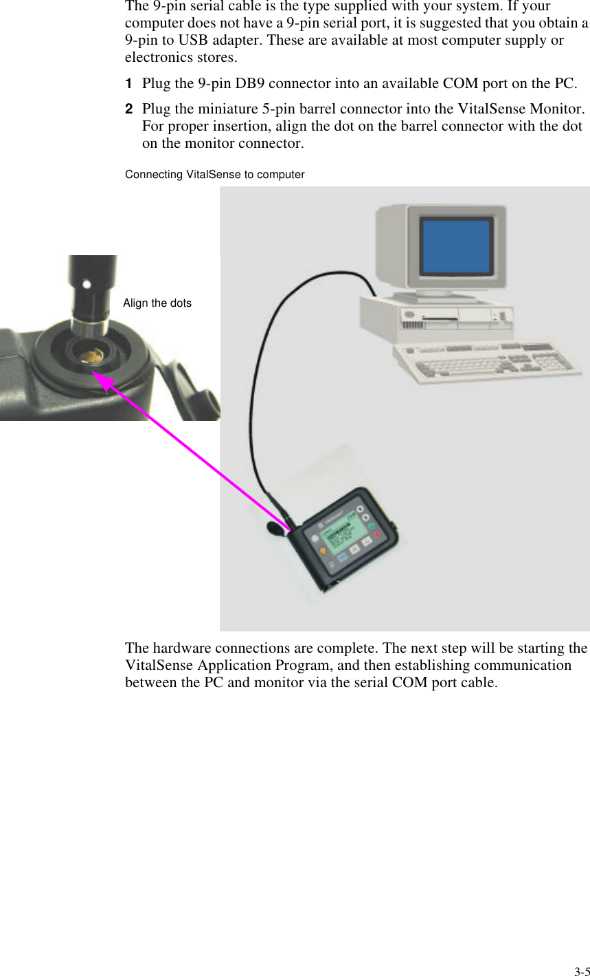
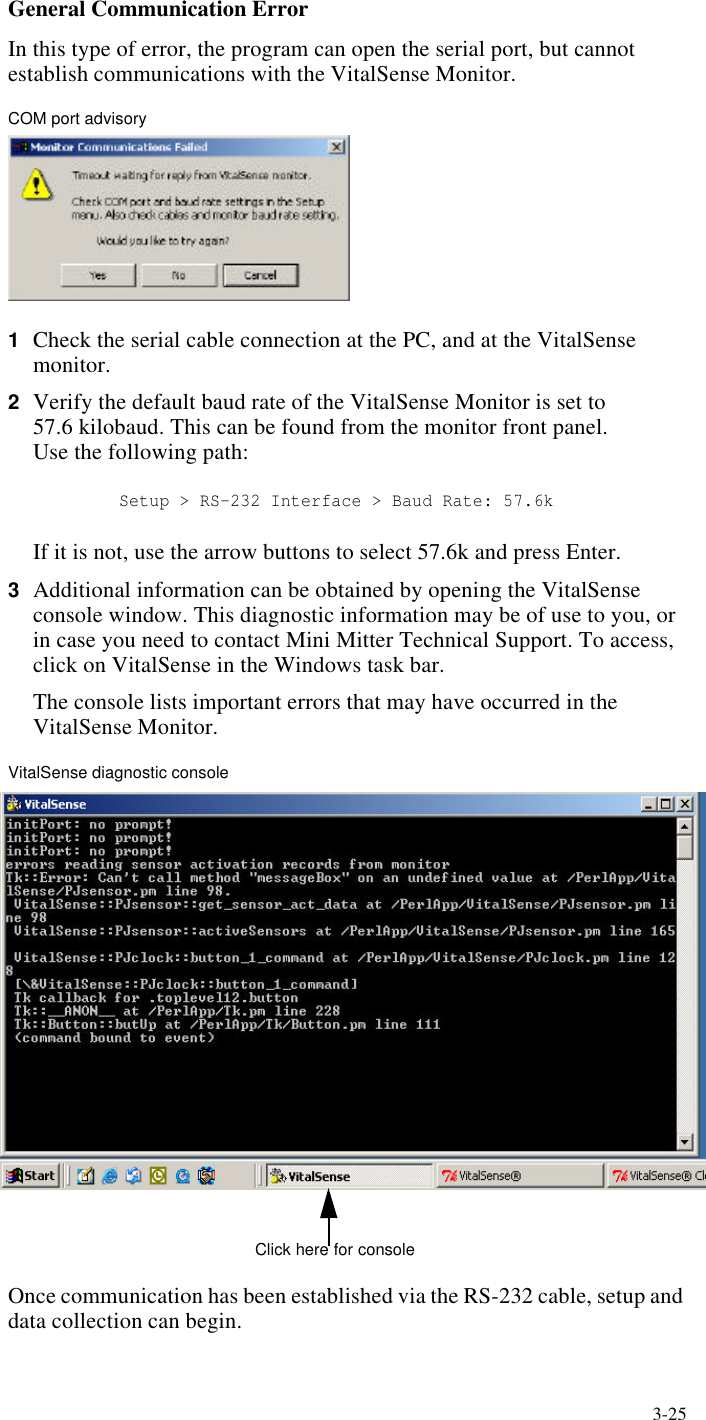
Mini Mitter Co. Inc. Integrated Physiological Monitoring System Tinman Book
Contents
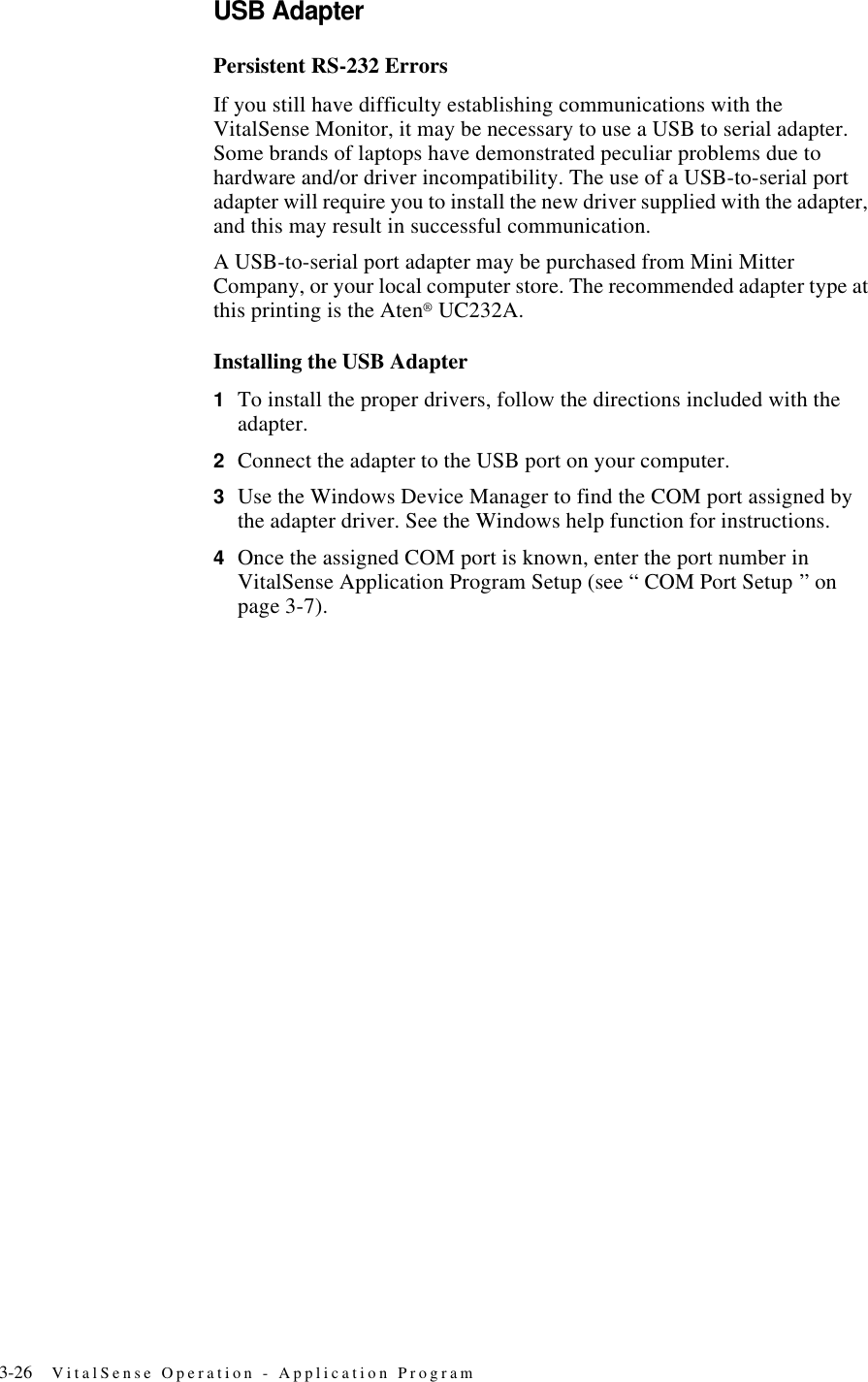
- 1. Users Manual
- 2. Users Manual part 1
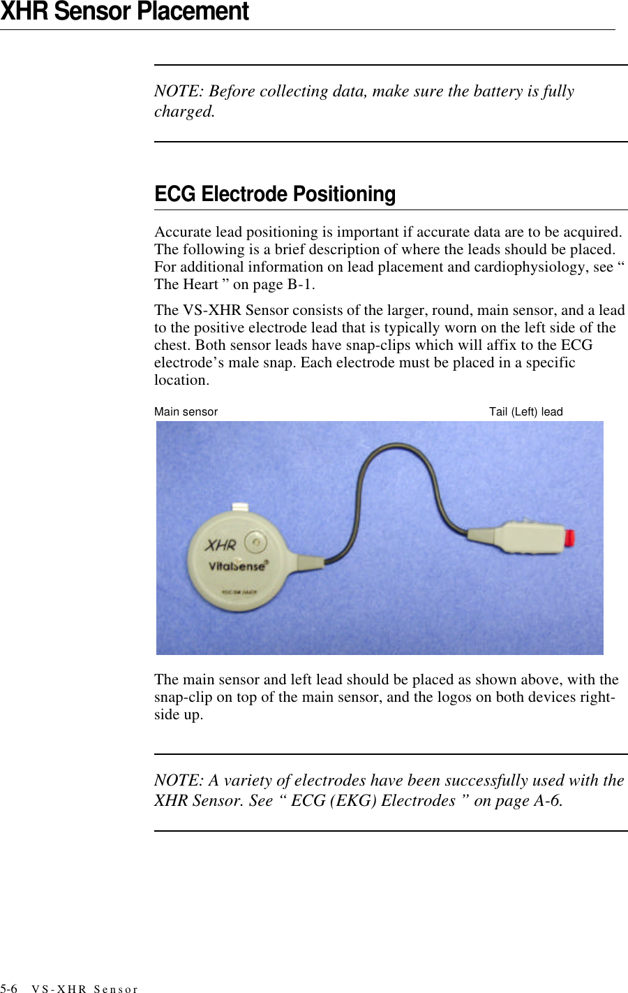
- 3. Users Manual part 2
Users Manual part 2