Mini Mitter XTP1 Integrated Physiological Monitoring System User Manual VitalSense Book
Mini Mitter Co. Inc. Integrated Physiological Monitoring System VitalSense Book
Contents
- 1. Users Manual
- 2. Users Manual part 1
- 3. Users Manual part 2
Users Manual

Mini Mitter Company, Inc.
Bend, OR USA
VitalSense
®
Integrated Physiological Monitoring System
Instruction Manual
This document is Mini Mitter Part Number 910-0500-Preliminary C
Copyright © 2003 Mini Mitter Company, Inc.
VitalSense
®
is a registered trademark of Mini Mitter Company, Inc.
PRELIMINARY
MINI MITTER COMPANY, INC.
WARRANTY POLICY
1. WARRANTY: Mini Mitter warrants that upon delivery the goods sold hereunder will be free of defects in materials and workmanship, and
such goods will substantially conform to the specifications furnished by the Seller, and to any drawings or specifications furnished to the
Buyer by Mini Mitter if approved by Mini Mitter.
a) Commencement of Warranty – The warranty period begins on the date of delivery.
b) Duration of Warranty – The goods sold hereunder are warranted for a period of twelve months, except PDT-4000 and PDT-4000HR, which
are warranted for two years.
c) Third Party Product Warranty – Third party products purchased by Buyer through Mini Mitter are covered by the manufacturer’s warranty
and ARE NOT COVERED BY THE MINI MITTER WARRANTY.
d) Place of Repair or Replacement. Buyer must return the defective or nonconforming goods upon request to Mini Mitter at 20300 Empire Ave-
nue, Building B-3; Bend, OR 97701, not later than 15 days after Mini Mitter’s receipt of notice of the alleged defect or nonconformance.
Buyer shall prepay transportation charges. Mini Mitter shall pay for the return of the goods to Buyer. No goods are to be returned to Mini
Mitter without prior authorization and a valid Corrective Action Request (CAR) number.
e) Limitation of Warranty The foregoing warranty shall not apply to defects resulting from (a) improper or inadequate maintenance by Buyer;
(b) unauthorized modification of the goods; (c) operation of the goods outside of the environmental specifications for the goods; (d) neglect,
misuse or abuse of the goods or (e) modification or integration with other goods not covered by a Mini Mitter warranty when such modifica-
tion or integration increases the likelihood of damage to the goods.
f) Technical assistance – The warranty set forth above shall not be enlarged, diminished or affected by and no obligation or liability shall arise
from Mini Mitter’s rendering of technical advice, assistance or services in connection with Buyer’s order of the goods furnished hereunder.
The Buyer is not relying on Mini Mitter's skill or judgment to select or furnish suitable goods.
THE WARRANTY SET FORTH ABOVE IS EXCLUSIVE AND MINI MITTER GIVES NO OTHER WARRANTY WRITTEN OR
VERBAL, EXPRESS OR IMPLIED. MINI MITTER SPECIFICALLY DISCLAIMS THE IMPLIED WARRANTIES OF MERCHANT-
ABILITY AND FITNESS FOR A PARTICULAR PURPOSE. MINI MITTER’S STANDARD WARRANTY POLICY COVERING
ANY MINI MITTER PRODUCTS SHALL BE NULL, VOID, AND OF NO EFFECT IF THE BUYER OR ANY THIRD PARTY USES
THAT PRODUCT FOR ANY USE OTHER THAN THE INTENDED USE OF THAT PRODUCT.
2. LIMITATION OF REMEDIES AND LIABILITY. The remedies provided herein are Buyer’s sole and exclusive remedies. Mini Mitter shall
have no responsibility other than, at Mini Mitter’s option, to repair or replace defective or nonconforming goods or to refund the purchase
price of defective or nonconforming goods in the event of breach of any warranty. IN NO EVENT SHALL MM BE LIABLE FOR ANY
DIRECT, INDIRECT SPECIAL, INCIDENTAL OR CONSEQUENTIAL DAMAGES (INCLUDING LOSS OF PROFITS) WHETHER
BASED ON CONTRACT, TORT OR ANY OTHER LEGAL THEORY. In the event that any limitation of warranty or disclaimer of liabil-
ity is found to be unlawful or inapplicable, or to have failed of its essential purpose, Mini Mitter’s liability shall be limited to the amount paid
by the Buyer for the specific goods that caused such liability.
900-0016-01

3
Thank You! .....for purchasing Mini Mitter products. If you need assistance with
VitalSense, remember Mini Mitter support continues after the purchase. If
you have any problems or questions, please call our Technical Support
staff of technicians, engineers, and scientists. We are available by
telephone, fax, e-mail, or website.
Contacting Mini Mitter Technical Support
Mailing and
Shipping
Address
Mini Mitter Company, Inc.
20300 Empire Avenue, Building B-3
Bend, OR 97701 USA
Telephone (800) 685-2999
(541) 322-7272
Fax (541) 322-7277
E-Mail mm@minimitter.com
Website www.minimitter.com

4
Notice to Practitioners and Subjects
Emissions
This equipment has been tested and found to comply with the limits for a
Class B digital device, pursuant to part 15 of the FCC Rules. These limites
are designed to provide reasonable protection against harmful interference
in a residential intallation. This equipment generates, uses and can radiate
radio frequency energy and, if not installed and used in accordance with
the instructions, may cause harmful inteference to radio communications.
However, there is no guarantee that interference will not occur in a
particular installation,. If this equipment does cause harmful inteference to
radio or television reception, which can be determined by turning the
equipment off and on, the user is encouraged to try to correct the
interference by one or more of the following measures:
• Reorient or relocated the receiving antenna.
• Increase the separation between the equipment and receiver.
• Connect the equipment into an outlet on a circuit different from that to
which the receiver is connected.
• Consult the dealer or an experienced radio TV technician for help.
Interference
This device complies with part 15 of the FCC Rules. Operation is subject
to the following two conditions:
• This device may not cause harmful interference.
• This device must accept any interference received, including
interferences that may cause undesired operation.
Modification of VitalSense Devices
CAUTION! Any changes to the VitalSense monitor or sensors not
expressly approved by Mini Mitter will void the practitioner or sub-
ject the authority to operate the devices.

i
Technical Support iii
Introduction 1-1
Monitor Setup/Operation - Front Panel 2-1
Monitor Setup/Operation - Software 3-1
Maintenance 4-1
Specification 5-1
Frequently Asked Questions A-1
System Diagnostic B-1
Index
Table of Contents
ii

1-1
SECTION
C
HAPTER
1
V
ITAL
S
ENSE
S
YSTEM
I
NTRODUCTION
This is an instruction manual for the operation and maintenance of the
VitalSense Integrated Physiological Monitoring System. This wireless
system consists of the following components:
VitalSense
Components
• Monitor
• Dermal Patch Sensor
• Capsule Sensor
Once a sensor is activated, it measures temperature data four times per
minute, and reports on average of four times per minute to the monitor.
The temperature data is timestamped and recorded for the measured time.
Up to ten sensors may be monitored. In order to do this, each sensor must
be activated by the monitor that will be recording that particular sensor.
During activation, each sensor and the monitor are synchronized.
IMPORTANT!
•Section Two of this manual explains the operation of the VitalSense
System as controlled from the front panel of the VitalSense monitor.
This is a “stand alone” section independent of Section Two, assuming
you are operating VitalSense from the monitor front panel.
•Section Three of this manual explains the operation of the VitalSense
System controlled from the Application Software. This is a “stand
alone” section independent of Section one, assuming you are operating
VitalSense from the Application Software.

1-2 Introduction
Sensors
VitalSense sensors are activated from the VitalSense monitor. Once
activated, a sensor will begin its monitoring assignment, and will continue
to do so until the battery expires (approximately 240 hours), the sensor is
removed from the sensor schedule, or the sensor is disposed.
Sensor activation is a key event in the operation of VitalSense. It is used to
synchronize the monitor with a sensor. Once activated, the monitor can
display the incoming data in real-time streaming, or log the data to the
non-volatile memory for future transfer to a computer.
Each sensor is given an identity number at the factory, along with
temperature calibration data. During activation, these data are retrieved
from the sensor and stored in the monitor memory.
All sensors are activated using essentially the same process:
• A specific optical signal from the monitor activates the sensor.
• By radio, the sensor transfers its identification and calibration data to
the monitor.
Following activation, the sensor is either swallowed (Capsule Sensor), or
affixed to the body (Dermal Patch Sensor). The activation process is
identical for each sensor.
2-1
SECTION
C
HAPTER
2
V
ITAL
S
ENSE
M
ONITOR
- O
PERATION
FROM
F
RONT
P
ANEL
VitalSense Monitor - Description
The VitalSense Monitor is a splash-resistant, battery-operated receiver
and logger. It activates the sensor by transmitting an optical beam,
receives data from the sensor by radio, records it in a non-volatile
memory, and facilitates transferring the data to a computer.
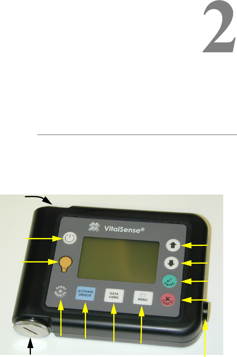
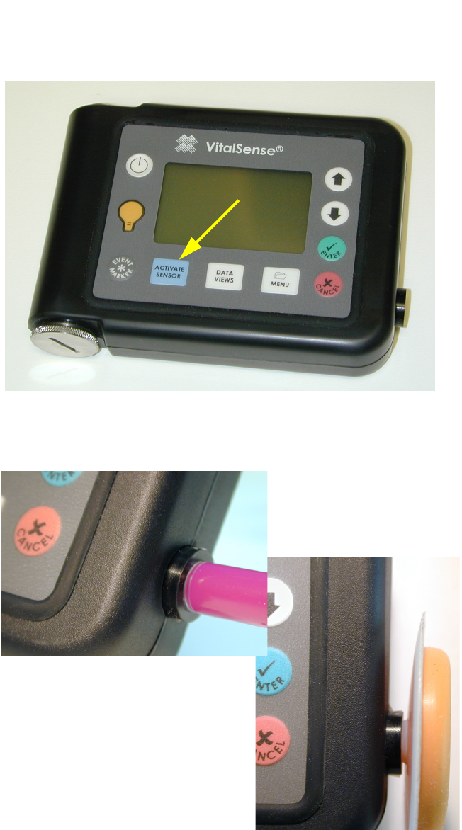
Monitor Front Panel
Power
Activate
Sensor
Data
View Menu
Up
Down
Enter
Cancel
Backlight
Marker
Button
Battery compartment
RS-232 port
(not shown)
Activation
Port
2-2 Monitor Operation - Front Panel
Controls
VitalSense controls are sealed, splash-resistant, and have tactile feedback.
• Power On/Off - Data are preserved when power is turned off
• Backlight - The backlight is activated for approximately 10 seconds
when this or subsequent keys are pressed
• Marker Button - Inserts a time mark into the recorded data
(The Marker button is currently disabled)
• Data Views - Toggles between the Multiple Sensor list and the data
graph chosen from the Multiple Sensor list
• Activate Sensor - Begins process of activation and automatic ID of
sensors
• Menu - Front panel access to main menu
• Cancel - Exits various functions, cancels changes, etc.
• Enter - Activates functions, inputs changes, etc.
• Down Arrow - Selects menu items or decrements parameters
• Up Arrow - Selects menu items or increments parameters
Other features
• RS-232 Port - Accepts RS-232 cable to facilitate transfer of data
• Battery compartment - Access to lithium power source
• Activation Port - Activates sensor during activation procedure
2-3
Initial Monitor Setup for Data Collection
Before data collection can begin, the monitor must be set up, or
configured. This configuration can be done from the PC through the RS-
232 port of the monitor, or from the monitor front panel. This section will
cover monitor front panel operations.
There are four operations that should be accomplished to assure the
monitor will collect data:
• “ Set to Factory Default ” on page 2-3
• “ Adjusting the Time/Date ” on page 2-6
• “ Erase Data Memory ” on page 2-11
• “ Activating Sensors Using the VitalSense Monitor ” on page 2-15
Some or all of the first three items may not be necessary if, for example,
you have configured VitalSense previously, erased the memory, or if you
have already set the time.
Set to Factory Default
This procedure insures that during initial setup, the default settings are
displayed and the subsequent setup procedure can be followed without
confusion.
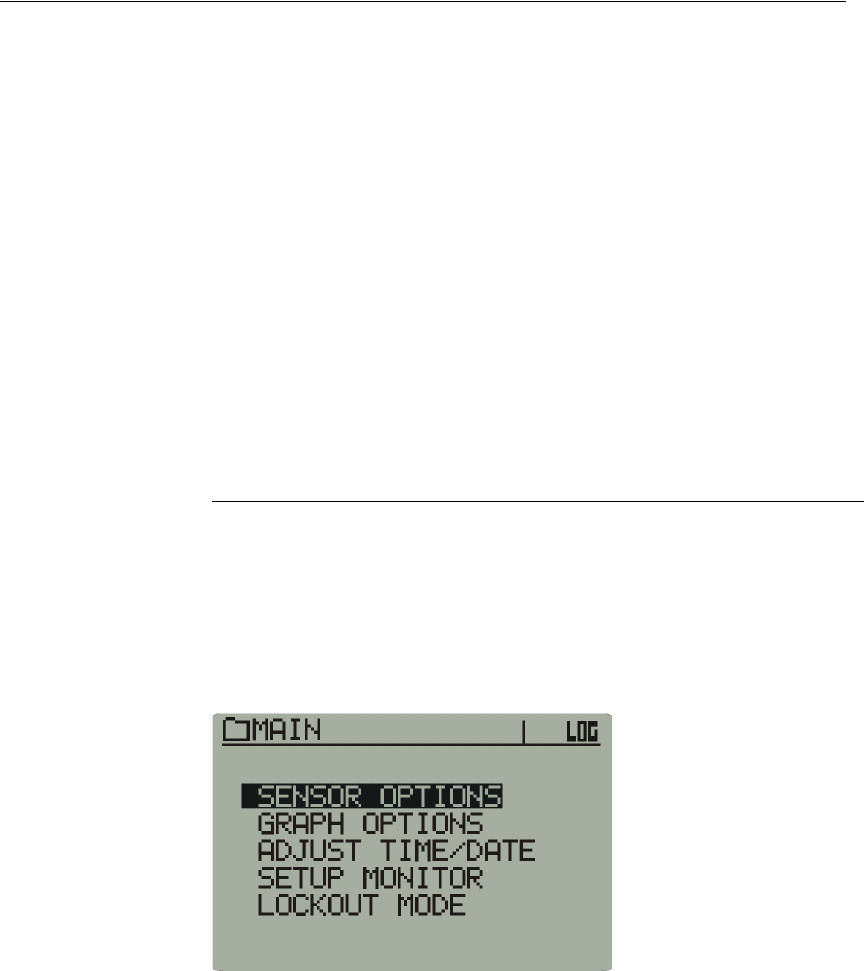
1Press the power button on the Monitor front panel. The following Main
menu will appear.
Main Menu
2-4 Monitor Operation - Front Panel
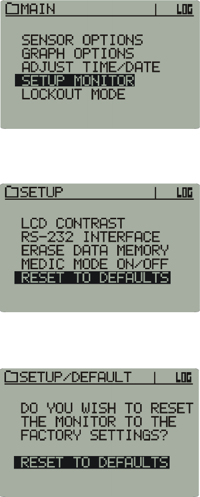
2Using the arrow buttons, highlight Setup Monitor, and press Enter.
Setup Monitor
3Using the arrow buttons, highlight Reset to Defaults, and press Enter.
Set to Defaults
4A warning will appear. Select OK, and press Enter.
Warning prompt
The Monitor is now set to the factory default settings.

2-5
Time and Date Time and date must be set carefully. VitalSense data is collected with
UTC (Universal Coordinated Time) as a reference. However, the monitor
can display Local time as well as Daylight and Standard times.
If the UTC or Local times, and the UTC offset are entered correctly,
VitalSense can compensate between Standard and Daylight time, and take
into account your PC’s clock.
CAUTION! When collecting data from sensors which are on line, do
not change the time setting or the sensor may be lost.
A note on UTC UTC, or Universal Coordinated Time, is based on precise atomic clocks,
shortwave time signals, and satellites. This insures that there is a reliable,
accurate standard for scientific and navigation purposes.
The difference between local time and UTC is called the UTC offset.
2-6 Monitor Operation - Front Panel
Adjusting the Time/Date
In the following instructions, use the arrow keys to navigate through the
menus and increment and decrement the highlighted choices.
NOTE: Although the clock functions are accessible from the moni-
tor front panel, it is easier to change them from the VitalSense soft-
ware on your PC.
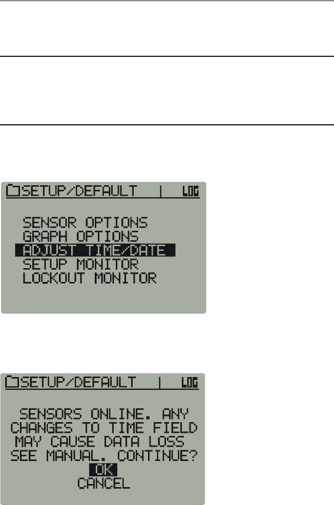
1From the Main menu, select Adjust Time/Date and press Enter.
Adjust Time/Date
2If you have sensors on line, you will receive a warning.
Sensor on-line warning
3Use the up and down arrows to select either OK or Cancel, and press
Enter.
2-7
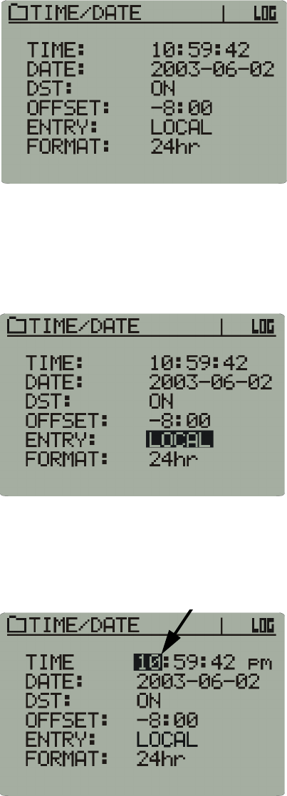
4The following menu is the Time/Date display. To make changes, use
the arrows to navigate to the desired location, and press Enter. Then,
use the arrows to make your selection.
Time/Date menu
Setting the Local Time and Date
This procedure will set the Monitor to Local time.
1The factory default for the Time/Date menu selection is Local.
Local time
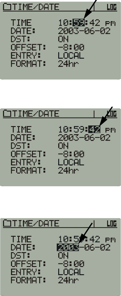
2Use the arrows to navigate to the hour as shown below. (The selection
will default to the hour when the Time/Date menu is selected.) Press
Enter. Use the arrows to increment and decrement the selection. Press
Enter to input the selection.
Hours selected
2-8 Monitor Operation - Front Panel
3Use the arrows to navigate to the minutes. Press Enter. Use the arrows
to increment and decrement the selection. Press Enter to input the
selection.
Minutes selected
4Continue this procedure to change the seconds.
Seconds selected
5This procedure is also used to change the date, beginning with the year.
Year selected
2-9
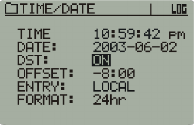
Daylight Savings Time Auto-Set
VitalSense will automatically compensate for the change of Daylight
Savings Time to Standard Time and back again based on the Monitor’s
time and date settings. However, this feature can be turned off.
1Use the arrows to navigate to Daylight Savings Time On, and press
Enter. Use the arrows to toggle between On and Off.
Daylight time selected
2Press Enter to input your selection.
2-10 Monitor Operation - Front Panel
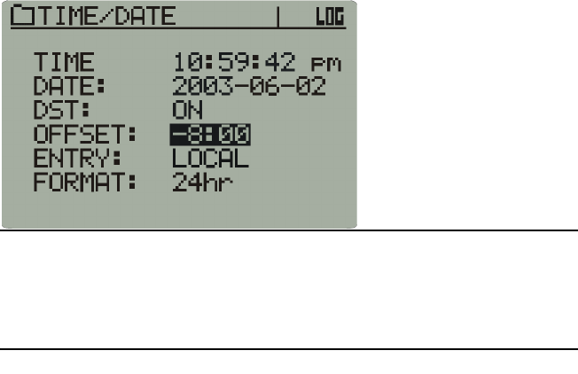
Setting the UTC Offset
Setting the UTC Offset sets the differential between Local Time and the
UTC time, not including Daylight Savings time. The SDT setting may
contribute an additional 1-hour offset based on the date, if enabled. For
more information on UTC, see “ A note on UTC ” on page 2-5.
UTC Offset
NOTE: All data are saved in UTC regardless of whether UTC or
local time is displayed. When data are transferred to the PC, it can
be displayed in local or UTC time.
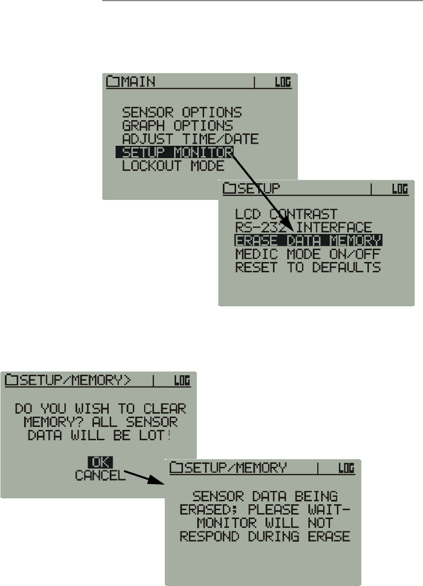
2-11
Erase Data Memory
Prior to collecting data, the data memory should be erased to provide
maximum storage capacity.
1Use the Up/Down controls to access Erase Data Memory.
Setup Monitor > Erase Data Memory
2Use the Up/Down controls to select OK. Memory erasure will take up
to 30 seconds. The monitor front panel will be locked out until the
memory is cleared.
Memory erase safety prompt
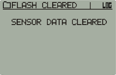
2-12 Monitor Operation - Front Panel
3You will be prompted when the memory is clear.
Memory clear prompt
2-13
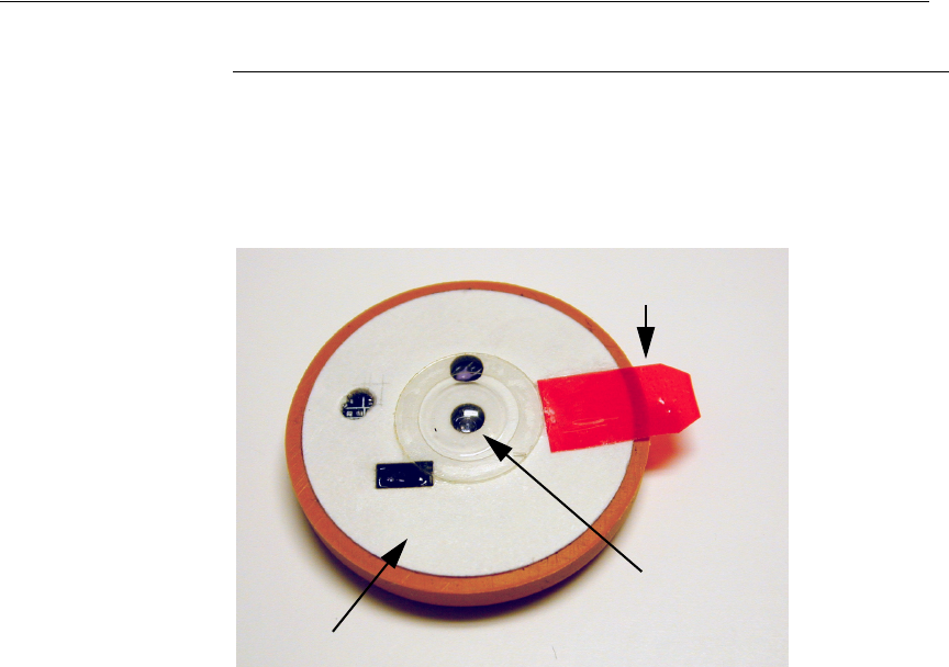
Precautions Prior to Activating the Dermal Patch Sensor
CAUTION! - Read before activating patch sensor!
The VitalSense Dermal Patch Sensor is a wireless, miniaturized,
externally activated, temperature monitoring device that is attached to the
skin with a pressure sensitive adhesive (PSA) release liner. There are
precautions associated with this device.
Dermal patch
• DO NOT remove the Dermal Patch Sensor from the package until it is
to be activated.
• DO NOT remove the release liner prior to activation.
• Activate the Dermal Patch Sensor prior to application. It cannot be
activated once affixed to the body.
Release liner tab
Lens
Release liner
2-14 Monitor Operation - Front Panel
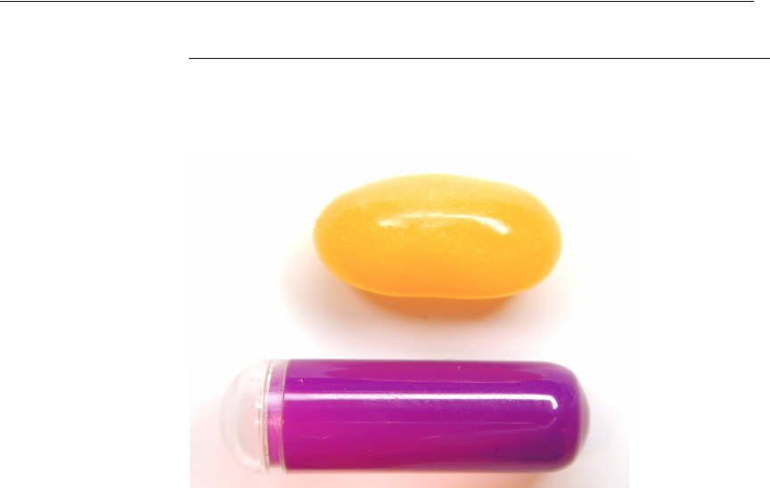
Precautions Prior to Activating the Capsule Sensor
CAUTION! - Read before activating capsule!
There are precautions associated with the Capsule Sensor prior to
activation.
Comparative Size
• DO NOT remove the Capsule Sensor from the package until it is to be
activated.
• Activate the Capsule Sensor prior to swallowing. It cannot be activated
once swallowed.
Capsule Sensor
Jelly bean
2-15
Activating Sensors Using the VitalSense Monitor
1The process of sensor activation begins by pressing Sensor Activation
on the front panel.
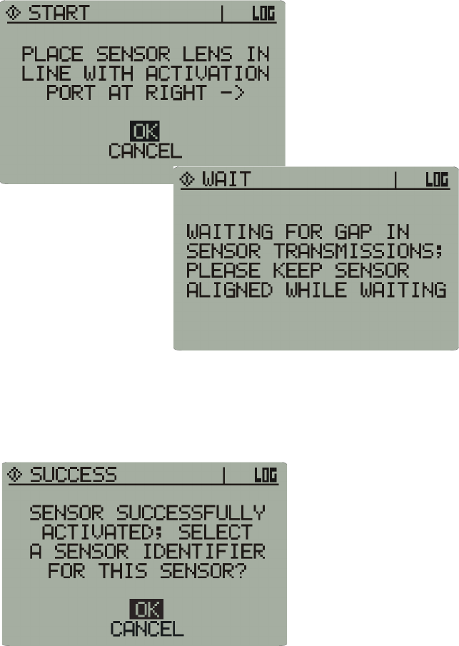
2Follow the directions on the display. First, place the sensor lens against
the optical port. Press Activate Sensor.
Activation Port alignment
Dermal patch sensor
Capsule sensor
2-16 Monitor Operation - Front Panel
3During the activation prompt (below), do not remove the sensor from
the Activation Port.
Attempting to activate
4You will be informed when the sensor has been successfully activated,
and you will be asked if you want a sensor identified, or labeled. If you
choose OK, you may append the identity number of the sensor with
additional information.
Successful activation
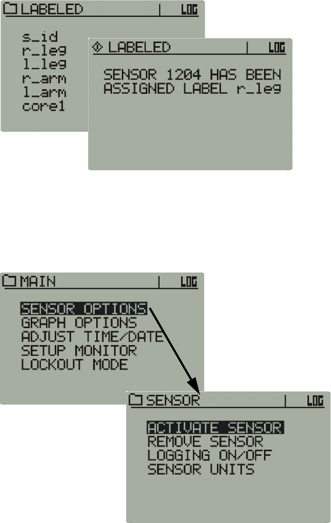
5Choose the appropriate identifier for the sensor, and press Enter. In the
illustrations below, the Right Legis the label for sensor 1204.
2-17
Sensor identifier
6The sensor activation is complete. For additional sensors, repeat the
procedure.
Sensor activation can also be initiated from the Main menu as shown
below. It is, however, physically easier to hold the sensor and use the
Activate Sensor key.
Main display
2-18 Monitor Operation - Front Panel
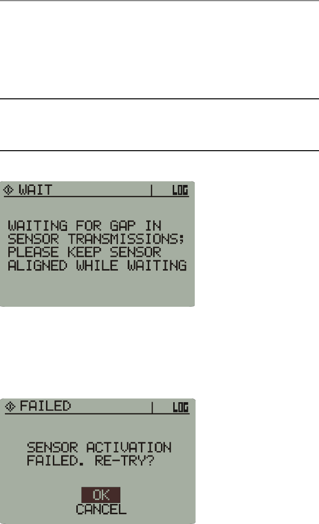
Sensor Does Not Activate
Failure to activate immediately
If the sensor does not activate with a few seconds, it may be waiting for a
transmission from a previously activated sensor. Hold the sensor in place.
Once the transmission has been received, the monitor will activate the new
sensor.
NOTE: As more sensors are brought on line, the monitor may need
to wait for longer periods.
Activation failure notice
Failure to activate
If a sensor fails to activate, you will be prompted. There may be several
reasons for non-activation.
Sensor activation failed
• Wait approximately 5 second and try again.
• Check that the sensor lens is aligned properly with the activation port.
• Attempt to re-try at least 3 times. If still not activated, return the sensor
to Mini Mitter for analysis.
2-19
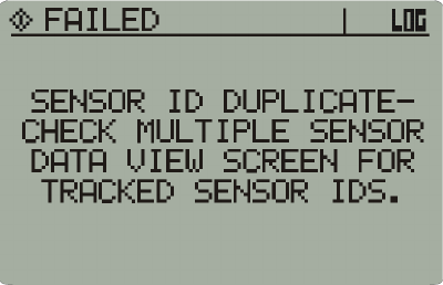
Duplicate sensor
The sensor will not activate if the identification number of the sensor is
identical to one already in the monitor schedule.
Duplicate sensor notice

2-20 Monitor Operation - Front Panel
Capsule Sensor - Indications and Contraindications
CAUTION! - Read before administering capsule!
Description
• Supplied as one Capsule Sensor per package
• Sensor is biocompatible, colored plastic
• Temperature Sensing Range: 25 °C to 50 °C
• Reception Range: approximately 1 meter
• Operating Time: up to 240 hours
Indications
• The VitalSense Capsule Sensor is a wireless, miniaturized, externally
activated, ingestible, biocompatible thermometer.
• It is to be used for monitoring vital signs (core body temperature) as
part of a complete physiological sensor and monitoring system.
• Once ingested, the patient is not restricted to a medical environment.
• It is a single-use sensor.
• Federal law restricts this device for sale by or on the order of a
practitioner licensed by the law of the State in which he/she practices to
use or order the use of this device.
Contraindications
This device is contraindicated if the patient presents or has a history of any
of the following conditions:
• Abnormalities in swallowing
• Esophageal or bowel strictures
• Fistulas
• Gastrointestinal obstructions
If suspected, the should consider a contrasted X-ray series prior to
ingestion.

2-21
Warnings
A warning indicates a condition that may endanger the patient.
• DO NOT ingest if any damage is visible to the packaging or the device.
• DO NOT chew prior to swallowing. The electronics within the device
will be made inoperable.
• The Capsule Sensor may be taken without regard to dietary restrictions.
It is, however, recommended that the device be swallowed with water.
• DO NOT attempt an MRI (magnetic resonance imaging) if this device
has recently been ingested. Wait until the device is passed from the
digestive system.
• DO NOT enter areas of extreme EMI (electromagnetic interference)
which may cause interference.
• DO NOT administer a Capsule Sensor after the expiration date.
• If gastrointestinal discomfort occurs following ingestion, report it to the
health care practitioner. Nausea, vomiting, or pain should be reported
immediately.
• Keep Capsule Sensors away from small children. They can be a
choking hazard.
Precautions
A precaution indicates a condition that may damage the equipment or
provide erroneous or incomplete data.
• DO NOT enter areas of extreme EMI (electromagnetic interference))
which may cause interference such as in-band radio transmissions, arc
welders and similar devices.
• DO NOT administer a Capsule Sensor after the expiration date.
• DO NOT leave the monitor out of range of the Capsule Sensor for more
than one hour.
• DO NOT open the VitalSense Capsule Sensor protective packaging
until ready for use.
• The Capsule Sensor should only be administered by a health care
practitioner.
• The VitalSense Monitor battery level should be checked prior to use.
Adverse Reactions
• May cause choking. Should be taken with water.
• In rare instances, may become lodged in the intestines.

2-22 Monitor Operation - Front Panel
Administration
1DO NOT CHEW. Swallow whole with water.
2Place the VitalSense Monitor close to the patient’s body, using the
accessory belt pouch, or a waist strap or neck strap.
3During bathing or showering the VitalSense monitor should be
removed from the subject. Removal is limited to one hour.

2-23
Dermal Patch Sensor Administration
CAUTION! - Read before administering Dermal Patch
Sensor!
Description
• Supplied one Dermal Patch Sensor per package
• Patch is biocompatible, colored plastic
• Temperature Sensing Range: -20 °C to 60 °C
• Reception Range: 2 meters
• Operating Time: 240 hours
Indications
• The VitalSense Dermal Patch is a wireless, miniaturized, externally
activated, dermally affixed, biocompatible thermometer.
• The Dermal Patch Sensor is to be used for monitoring vital signs
(external skin temperature) as part of a complete physiological sensor
and monitoring system.
• The subject is not restricted to a medical environment. The subject may
shower and participate in normal activities while the Dermal Patch is in
place.
• The Dermal Patch is a single-use sensor.
• Federal law restricts this device for sale by or on the order of a health
care practitioner licensed by the law of the State in which he/she
practices to use or order the use of this device.
Contraindications
• This product is contraindicated if the patient has known skin allergies, a
break in the skin at the application site, or other abnormal skin
conditions.If a skin rash occurs, notify the health care practitioner
immediately.

2-24 Monitor Operation - Front Panel
Warnings
A warning indicates a condition that may endanger the patient.
• DO NOT affix Dermal Patch if any damage is visible to the packaging
or the device.
• DO NOT attempt an MRI (magnetic resonance imaging) if a Dermal
Patch has been affixed. Remove the device prior to MRI.
• DO NOT enter areas of extreme EMI (electromagnetic interference)
which may cause interference.
• DO NOT administer a Dermal Patch Sensor after the expiration date.
• Keep sensors away from small children. They can be a choking hazard.

2-25
Precautions
• The Dermal Patch Sensor should only be administered by a health care
practitioner.
• Following activation, the Dermal Patch Sensor can be affixed to nearly
any flat, hairless area on the body. Placement, however, is limited to the
size of the patch. It cannot be trimmed or altered, and should not be
bent or crushed. It would, for example, be appropriate for a large
muscle of the arm or leg, or axilla, but not on the bottom of the foot or
around a bony structure such as the side of the wrist.
• The Dermal Patch Sensor should be administered every 3 to 4 days or
when Patch looses contact with skin, or as directed by a health care
practitioner.
• DO NOT leave the monitor out or range of the Dermal Patch Sensor for
more than 1 hour.
Adverse Reactions
May cause skin rash. Remove hair and clean skin before activation and
application of Patch. If discomfort occurs or rash appears, discontinue use
and notify health care practitioner.
Administration
1Select a flat skin surface. Remove excess hair.
2Prepare skin with skin preparation wipe supplied with patch.
3Once Patch is activated, remove release paper and affix to skin.
Dermal Patch sensor properly affixed
4Place the VitalSense Monitor close to the patient’s body, using the
accessory belt pouch, or a waist or neck strap.
5
2-26 Monitor Operation - Front Panel
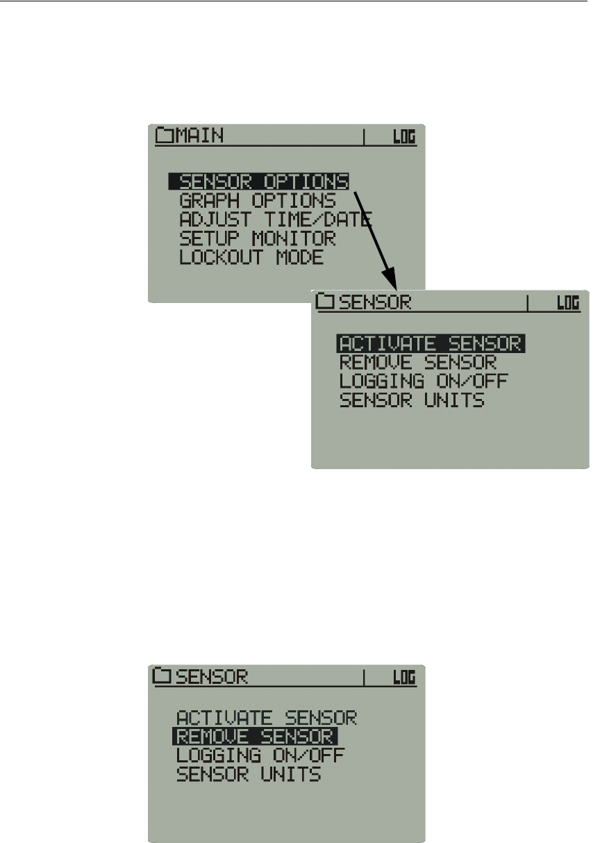
VitalSense Monitor Front Panel Details
The Main Menu is a gateway to several submenus. The first offers several
submenus of sensor options. The first is Activate Sensor.
Sensor
Options
Activate Sensor
Sensor options
This is identical to the function of the Monitor Activate Sensor button on
the front panel. See “ Sensor Activation ” on page 3-1.
Sensor
Options
Remove Sensor
The Remove Sensor function removes a sensor selected from the sensor
schedule.
1Select Remove Sensor from the Sensor Option list.
Remove Sensor sub-menu
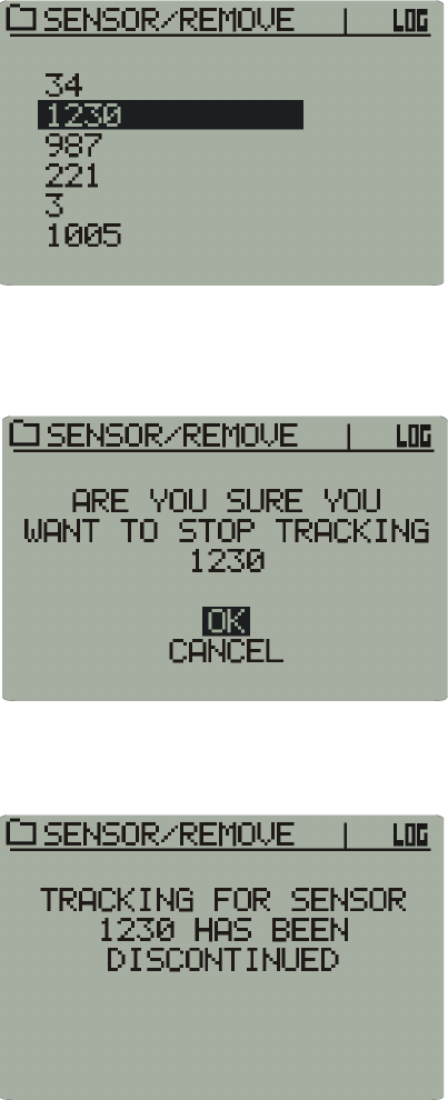
2-27
2From the sensor schedule, use the arrow buttons to select the sensor that
is to be removed. Press Enter.
Remove Sensor selection
3If you want to remove the selected sensor, choose OK.
Warning prompt
4The selected sensor will be removed from the sensor schedule.
Sensor removed from schedule
2-28 Monitor Operation - Front Panel
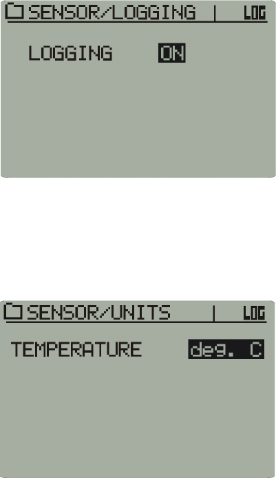
Sensor
Options
Logging ON/OFF
This function toggles the VitalSense Monitor logging on or off. If turned
off, the VitalSense monitor will continue to communicate with the
sensors, but the data memory will not log the data until it is toggled back
to On.
Logging on or off
Sensor
Options
Sensor Units
Use the arrow buttons to toggle between the temperatures displayed in °F
or °C.
Temperature display selection
2-29
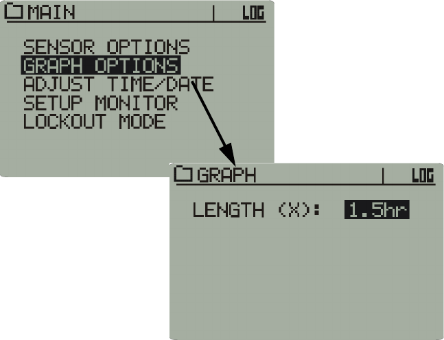
Graph Options
Graph
This function can expand or narrow the amount of temperature sensor data
displayed in the Data Views graph. Up to 48 hours of data can be
displayed. The following are the choices:
• 1.5 hours
• 3 hours
• 6 hours
• 12 hours
• 24 hours
• 48 hours
Graph
Adjust Time/
Date
This function has been documented previously under Monitor Setup.
Refer to “ Adjusting the Time/Date ” on page 2-3.
Setup Monitor This function has been documented previously in “ Monitor Setup ” on
page 2-1.
2-30 Monitor Operation - Front Panel
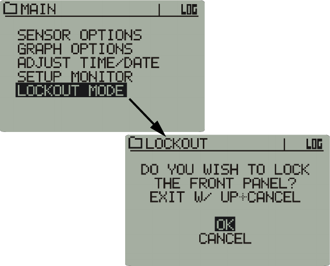
Lockout Mode Lockout mode gives the practitioner the abillity to lock the front panel
functions to prohibit unauthorized tampering of the settings.
1Click on OK to activate the lockout.
Lockout Mode
2To de-activate lockout mode, press and hold the up arrow, and press
Cancel. Normal operation of the front panel will commence.
2-31
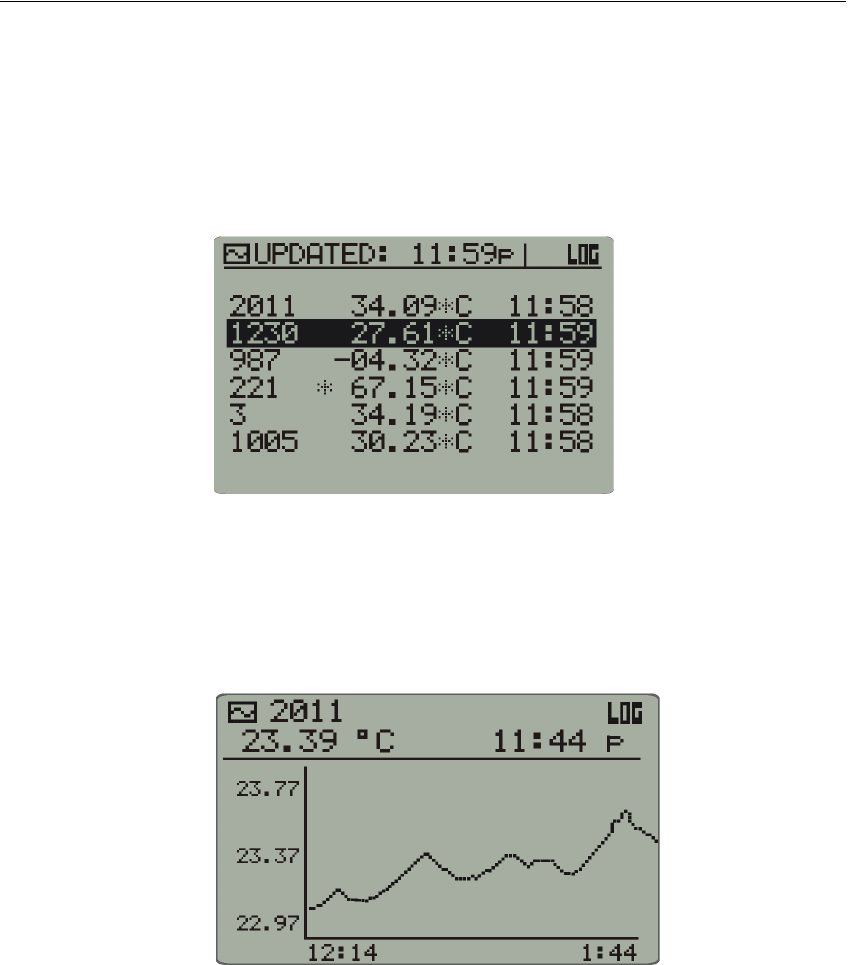
Data Views
Pressing the Data Views button on the Monitor front panel will toggle
between two means by which to view the sensor data: Graph and List.
1On the Monitor front panel, press the Data Views button. A list of
sensors will be displayed along with the temperature and time data.
(Use the up and down arrows to view sensor which may be off the
display.)
Data View list
2To view other sensors, use the arrows to scroll through the sensors that
are activated.
3To view a sensor in Graph mode, press Data Views once more. (To
change the amount of time shown on the graph, see “ Graph ” on
page 2-29).
Data Views graph
4You may toggle between Graph and List with the Data Views button.
To view other sensors in Graph mode, use the arrow buttons.

2-32 Monitor Operation - Front Panel
Out-of-Range Conditions
With respect to periodic hygiene, change of clothing, decontamination,
and other related tasks, it may be necessary to remove the VitalSense
Monitor from the working range of the sensors for short periods of time.
The VitalSense Monitor may be removed from sensor range for up to one
hour. Beyond one hour, VitalSense may have difficulty resynchronizing
with sensor transmissions. Beyond one hour, a significant loss of data may
occur. Previously logged data will be preserved in the monitor, but future
data collection may not be possible after extended periods of separation.
An asterisk will appear beside any sensor for which the last data
transmission was missed. The sensor data displayed will be the last valid
sensor data for that sensor.

3-1
SECTION
C
HAPTER
3
V
ITAL
S
ENSE
M
ONITOR
O
PERATION
-
FROM
A
PPLICATION
S
OFTWARE
Introduction
VitalSense Application Software is a software utility program that
communicates to the VitalSense monitor via an RS-232 cable. With this
link, a variety of functions can be accomplished from a PC.
• Setup of the VitalSense monitor.
• Setup and initialization of the sensors.
• Provides real-time temperature data.
• Retrieves recorded data from the VitalSense monitor.

3-2 Monitor Operation - Application Program
PC Preparation Prior to Installation
PC
Requirements
for VitalSense
•IBM
® Compatible PC
• Pentium® II Processor with a clock speed of at least 266 MHz
• 64 MB of RAM
•Windows
® ‘98, 2000, XP, Millennium, or Windows NT 4.0
•CD-ROM drive
• 4 MB of free space on the hard disk
• 9-pin or 25-pin RS-232 communications serial port
• Super Video Graphics Array (SVGA - 800 x 600 pixels required to
view all data displays)
• Printer (optional)
NOTE: Recommended is a Pentium® III or IV Processor, 866 MHz
to 1+ GHz, and 128MB or more of RAM.
Preferred
Settings
VitalSense software is best used with the following computer display
settings. Directions for changing these settings can be found in the Online
Help feature of your specific operating system.
Monitor area or monitor resolution
Set the resolution for 800 x 600 or higher. 1024 x 768 is
recommended.
Appearance scheme (or theme)
Avoid “High Contrast” or “Extra large” schemes. Windows
Standard is recommended.
Font sizes
For display items related to fonts and font sizes, select “Normal” or
“Small font” (font sizes of 12 points or less). Eight points is
recommended in the sense it will allow you to see more information
than larger point sizes.

3-3
Installation of Software
NOTE: Before beginning the installation procedure, make sure that
no other applications are currently running on the Host PC. This
includes MS Office® and any other utilities. These can interfere with
proper installation, resulting in software conflicts.
1The CD-ROM is set to auto-install. Load the CD into your drive, and
wait for the menu to appear.
2If your CD drive does not accommodate auto installation, click the Start
button, then Run, type D:\setup.exe, then click OK. (“D” is the letter
commonly used for the CD drive).
3At the next prompt, enter the destination directory for the installation.
The default is C:\Program Files\VitalSense. Click the PC icon to
proceed with the installation.
4If the installation is successful, a prompt will notify you. Click OK to
complete installation.
For convenience, you may create a shortcut to your desktop.
3-4 Monitor Operation - Application Program
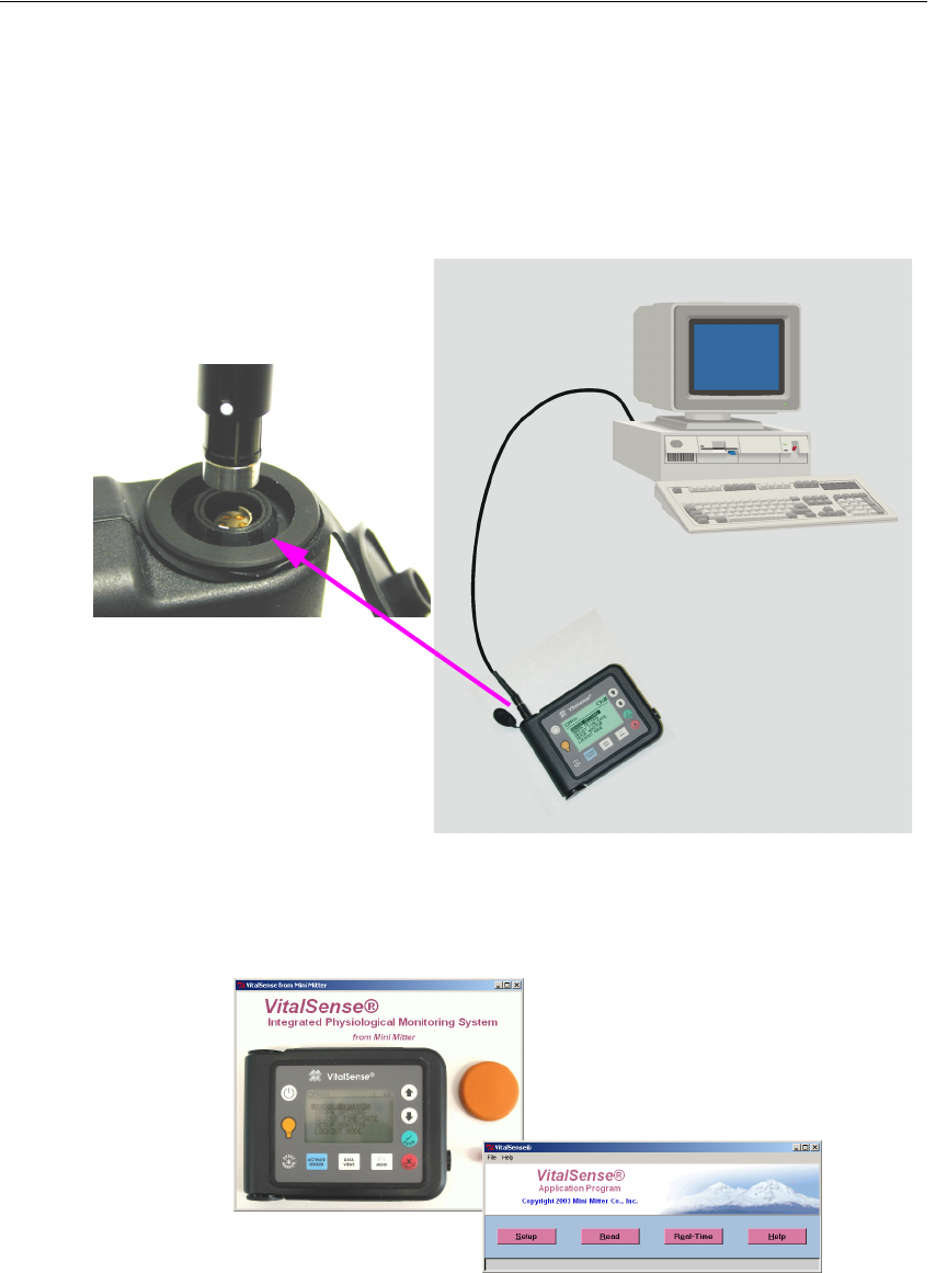
Connecting VitalSense Hardware
To connect the VitalSense monitor to a computer, use the RS-232 cable
supplied with the software.
1Plug the 9-pin DB9 connector into an available COM port on the PC.
2Plug the miniature 5-pin barrel connector into the VitalSense monitor.
Align the dot on the barrel connector with the dot on the monitor
connector for proper insertion.
Connecting VitalSense to computer
3To start the VitalSense Application program, click on the icon
established during installation. An introductory splash display should
appear, followed by the Main window.
Splash display
4If there are communication errors, refer to “ Establishing RS-232
Communications ” on page 3-5.
Align the dots
Main window
3-5
Establishing RS-232 Communications
When there is a failure to communicate, typically the cause of one of two
major COM port errors:
• COM port is already in use.
• General communication errors
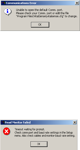
COM Port Already in Use
The VitalSense monitor default COM port is COM1. If the following error
appears, the COM1 port must be changed. This is done by editing the
configuration file.
COM port warning
1Open the configuration file using Wordpad, Notepad, etc. This file is
located in the VitalSense installation folder:
Program Files\VitalSense\vitalsense.cfg
2Change the second line in the file to match an available COM port, e.g.,
COM2.
3Save the file and restart VitalSense.
General Communication Error
In this type of error, the program can open the serial port, but cannot
establish communications with the VitalSense monitor.
COM port warning
1Check the serial cable connection at the PC, and at the VitalSense
monitor.
2Verify the default baud rate of the VitalSense monitor is set to 57.6K.
This can be found from the monitor front panel:
SETUP > RS-232 INTERFACE > BAUD RATE: 57.6K
3-6 Monitor Operation - Application Program
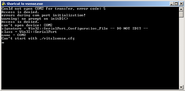
3Additional information can be obtained by opening the VitalSense
console window. This diagnostic information may be of use to you, or
in case you need to contact Mini Mitter Technical Support.
VitalSense console
Once communication has been established via the RS-232 cable, setup and
data collection can begin.

3-7
Initial Monitor Setup for Data Collection
This procedure is very similar to portions of “ VitalSense Monitor -
Operation from Front Panel ” on page 2-1. This section, however, contains
instructions on additional functions, such as retrieving data and real time
obsservation of data collection.
Before data collection can begin, the monitor must be set up, or
configured. This configuration can be done from the PC through the RS-
232 port of the Monitor.
There are three operations that should be accomplished to assure the
monitor will collect data:
• “ Options - Clear memory ” on page 3-9
• “ Setting the Clock ” on page 3-10
• “ Subject Information ” on page 3-11
Some or all of the items may not be necessary. If, for example, you have
configured VitalSense previously, erased the memory, or if you have
already set the time.
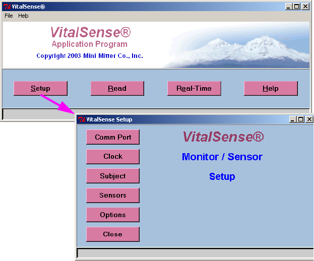
3-8 Monitor Operation - Application Program
Monitor/Sensor Setup
Setup begins with the Main display, and the Setup menu.
COM Port
If necessary, you may change the COM port by clicking on Comm Port,
and follow the directions.
3-9
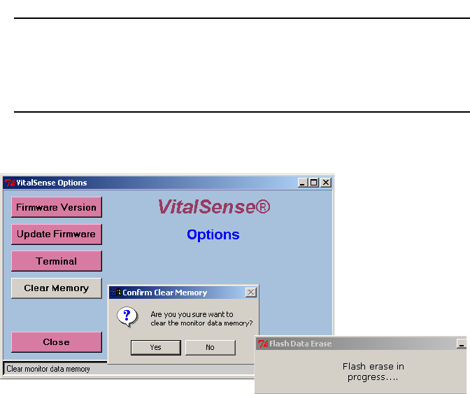
Options - Clear memory
If you are beginning a new data collection session, it is recommended that
you first erase the data memory. The data memory only pertains to data,
not the sensor or subject information.
NOTE: If you plan to change or delete subjects, this step may be
skipped. You will be given the opportunity to clear the data memory
at that time.
Clearing the data memory
3-10 Monitor Operation - Application Program
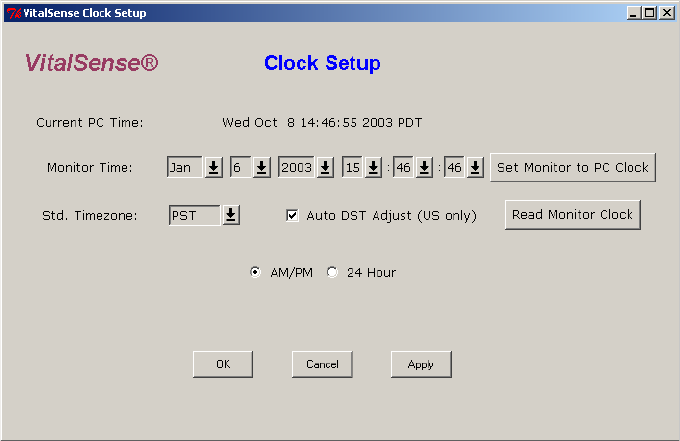
Setting the Clock
The Clock Setup is accessed from the Main window.
Main Window > Setup > Clock
There are two ways to change the time in the VitalSense monitor from the
Application Software.
• Selectively set each field individually, then click on Apply or OK.
• Click on Set Monitor Clock to PC Clock. The PC time will be entered
into the VitalSense monitor automatically.
3-11
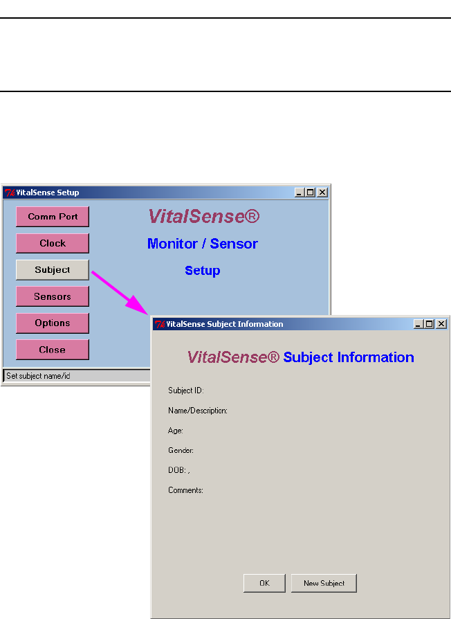
Subject Information
The VitalSense Application Software uses a wizard to enter subject
information into the monitor. This wizard is accessed from the Setup
window.
CAUTION! This wizard gives you the opportunity to erase the data
memory as well as sensor assignments.
1From the Setup window, click on Subject. To enter a new subject, click
on New Subject.
Main window > Setup > Subject
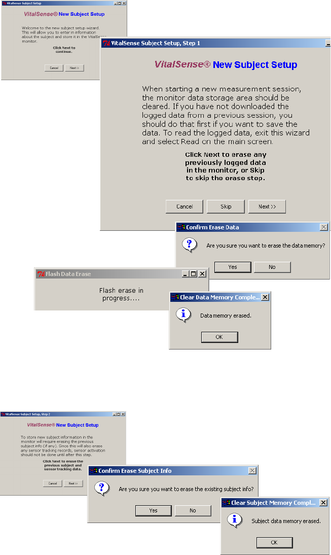
3-12 Monitor Operation - Application Program
2The wizard will suggest you download any previous data, and then
gives you the opportunity to erase the data memory. By clicking on
Next and the confirmation prompt Yes, the data memory will be erased.
The subject and sensor data will remain.
Data memory erasure
3Entering a new subject will result in any previous subject and sensor
information being erased.
Subject data erasure
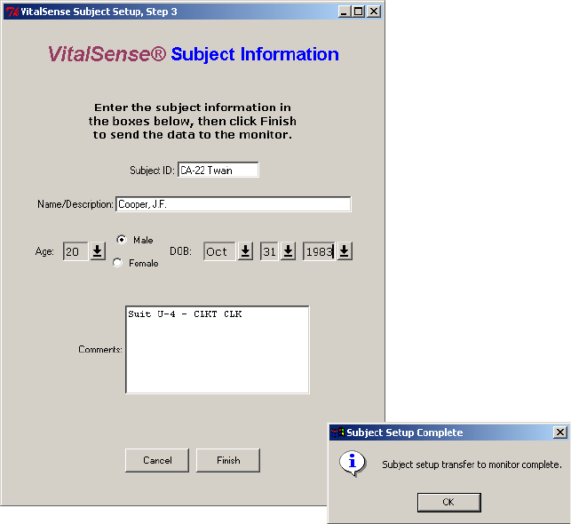
3-13
4New subject data can now be entered. Age and date of birth may be
entered using the arrows, or double-click-and-enter in each field.
5Click OK to complete the entry.
Subject data entered
3-14 Monitor Operation - Application Program
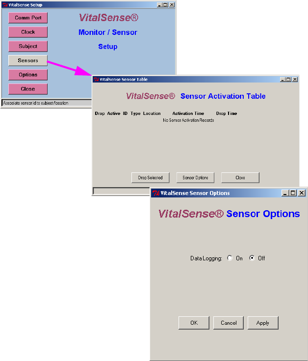
Sensors
Sensor logging may be toggled on or off from the VitalSense Application
Software.
Main window > Sensors
3-15
Read Data
This function retrieves the data from the VitalSense monitor.
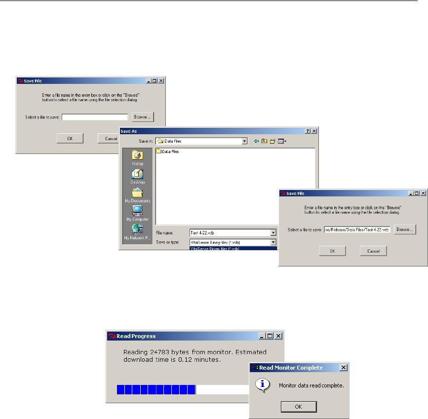
1Read is accessed from the Main window. Click on Read. You will be
prompted to name a file where this data is to be saved.
Read data
2The data may be saved as a VitalSense Binary File (.vsb), the default,
or a text file (.txt). Name the file, choose its location, and click on Save.
You will be prompted as to the progress of the data retrieval.
Data retrieval progress
3-16 Monitor Operation - Application Program
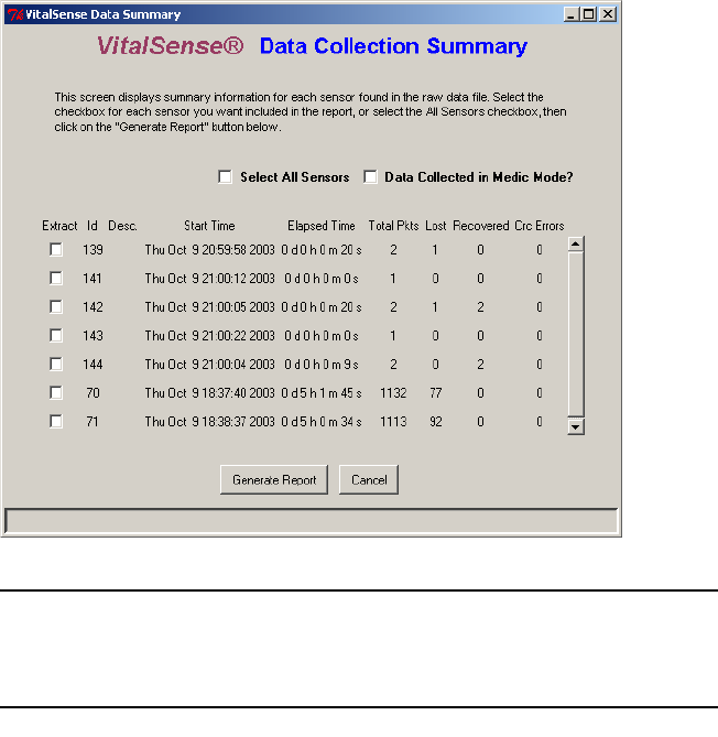
A Data Collection Summary will appear. This is essentially an “index” of
the data collected.
Data Collection Summary
NOTE: If you choose not to generate a report at this time, you may
use the Open File command and generate a report at a later time.
VitalSense Data Collection Summary
The table of sensors as shown above contains the following information
for each sensor listed:
• Sensor ID.
• Timestamp of first data record for that sensor.
• Elapsed time to the last data record for that sensor.
• Total number of packets, or measurement records.
• Number of lost packet (records with a timestamp outside the allowable
window.
• Number of recovered packets (a missing measurement recovered from
the “previous value” field on the next data packet.
• The number of CRC errors.
3-17
The data summary also includes the following functions:
• Extract check box selects the data you want to see.
• Data Collected in Medic Mode check box. When checked, lost packet
detection is disabled, since it is unknown when a packet is expected to
arrive.
• Generate Report starts the file extraction and decoding process.
• Cancel disables this function.
Generate Report
Two output files will be generated:
• A Microsoft Excel file with an .xls extension. The filename will remain
identical to the original Read Data filename.
• A plain text file with a .txt extension. The filename for the text file will
be comprised of the original Read Data filename, along with “_d_nnn.”
“nnn” is the sensor number.
Both files will be named after the original Read Data filename. To change
the filename, rename it using Windows Explorer.
3-18 Monitor Operation - Application Program
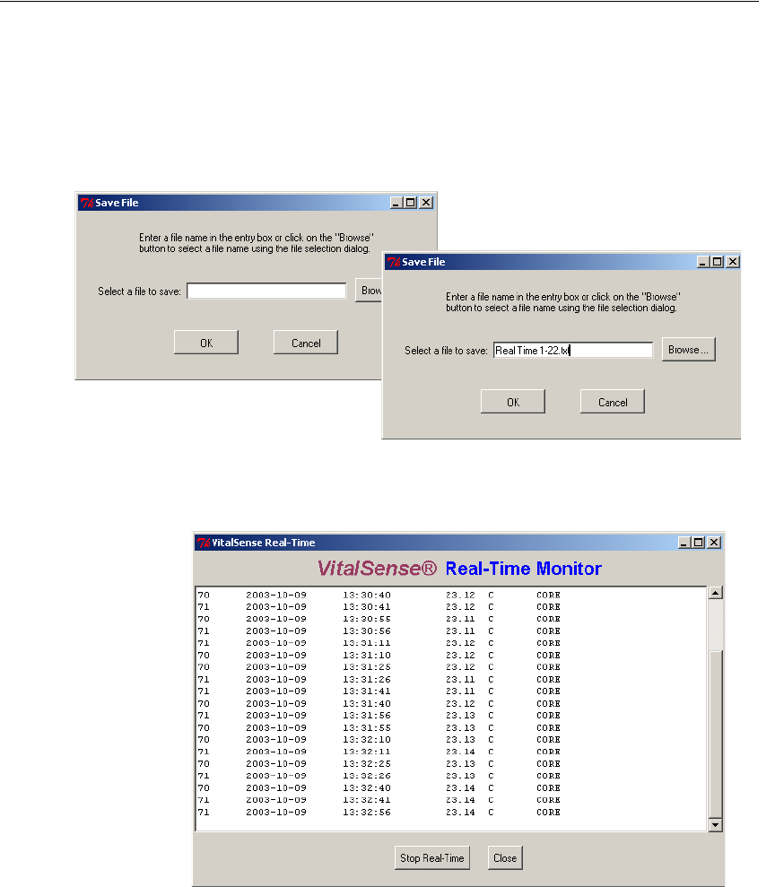
Monitoring Data in Real Time
Monitoring in Real Time allows data collection to be observed as it is
being saved.
1From the Main window, click on Real Time.
2You will be asked where the information is to be saved, and to name the
file. Once named, click OK.
Saving real-time data
3The following window will fill as the data begins to be retrieved.
Real-time data
4Click Close to stop the observation in real time. The data will be saved
in the above-named file.

3-19
Application Program Details
Setup
Options Firmware Query
Firmware Upgrade
Terminal Mode
Clear Memory
3-20 Monitor Operation - Application Program
4-1
SECTION
C
HAPTER
4
M
AINTENANCE
This section applies to the VitalSense monitor, including hardware
maintenance such as battery replacement, cleaning, and sterilization.
Battery Replacement
NOTE: The sensor batteries cannot be replaced. These instructions
are for the VitalSense Monitor.
A low battery condition will be indicated on the front panel display by a
battery icon. However, a low battery indication may vary according to the
display that is currently chosen.
Low battery warning
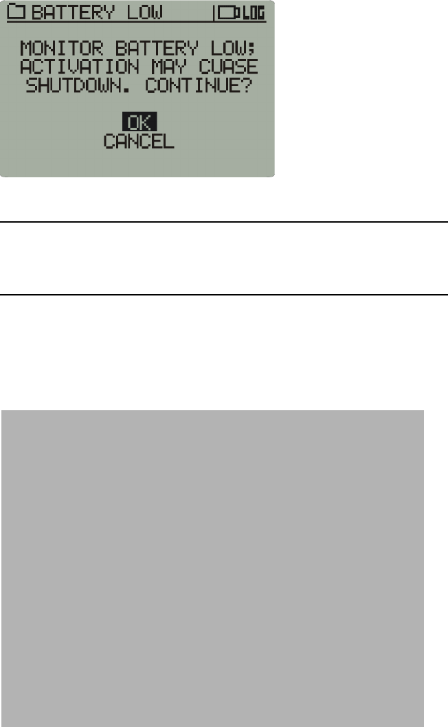
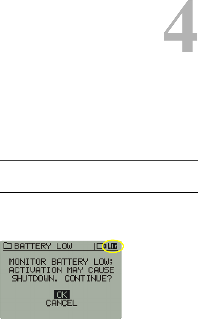
4-2 Maintenance
If attempting to activate sensors during a low battery condition, the
following cautionary statement may appear. An attempt to activate sensors
during this condition may result in the monitor shutting down.
Monitor shutdown precaution
NOTE: While replacing the battery, the non-volatile memory will
retain the acquired data.
1Press the power button to turn the VitalSense Monitor power off.
2The VitalSense Monitor battery is located in the battery compartment,
and is accessible from the bottom of the device as shown below.
Monitor battery compartment
3Remove the lithium cell by unscrewing the battery compartment cover.
If necessary, you may use a coin or screwdriver.

4-3
WARNING! Do not dispose of lithium batteries in fire or flame. An
explosion may result. Only dispose in accordance with manufac-
ture’s recommendation, or local codes.

4-4 Maintenance
4Replace the battery as shown below, with the positive end inserted first.
Replacement battery inserted
5Replace the battery compartment cover, and finger-tighten. Do not
overtighten.
6Press the power button to turn the Monitor power back on.
NOTE: If sensors are active, VitalSense will re-establish communi-
cation with them and begin data acquisition. This may take a few
minutes.
Cleaning
Cleaning of the VitalSense monitor can be accomplished by wiping the
surface with a soft, damp cloth. A mild detergent and water can be used to
remove dirt and stains. Do not use abrasives or alcohol. The seals and
display may be damaged.
Sterilization

5-1
SECTION
C
HAPTER
5
S
PECIFICATION
Parameter Value Condition/Note
Physical Attributes
(Monitor)
Size 120 x 90 x 25mm Outside dimensions
Weight 200 grams Monitor only
Case material Polycarbonate/ABS co-
polymer
Interface Panel Non-permeable membrane
switch
Display Monochrome LCD with
backlight
Physical Attributes
(Capsule Sensor)
Capsule appearance Purple, cylindrical, with
hemispherical ends
Size 8.6 mm O.D. x 23mm
long
Total
Weight 1.6 grams
Capsule Material Plastic
Physical Attributes
(Dermal Patch Sensor)
Patch appearance Tan or off-white, circular,
flat
Size 36.5mm O.D. x 5.8mm
thick
Total
Weight 7.5 grams
Encapsulation material Silicone rubber
Dermal contacting surface Biocompatible
polyurethane foam

5-2 Specification
Parameter Value Condition/Note
Functional Attributes
Temperature sensing range 25 °C to 50 °C Ingestible capsule
-20 °C to 60 °C Dermal patch
Temperature sensing accuracy ±0.1 °C
±0.25 °C
±0.25 °C
32 °C to 42 °
-20 °C to 32 °
42 °C to 60 °
Temperature display resolution ±0.01 °C
Display update rate 15 seconds Average
Monitor battery life 10 days with 10 sensors
on line, plus 20 days
standby
Battery life increases with
fewer sensors on line
Sensor battery life 1 year storage plus 10
days active transmission
Capsule and patch
Calibration None required
Number of co-active sensors One to ten Per monitor
Sensor identification Automatic tracking
Crosstalk Not allowed
Environmental Attributes
Moisture protection IEC529-IP52
NEMA 250-5
Storage temperature -20 to 50 °C @ 5-95% humidity
Operating temperature 0 to 40 °C
Radio Frequency Attributes
Transmission radio carrier
frequency
40.68 MHz ISM band (capsule and
patch)
Typical transmission range 1 meter
2 meters
Capsule sensor
Dermal Patch
Software/PC Attributes
Software features Data transfer, ASCII
conversion
Compatibility Windows 2000, NT, XP
Communications interface RS-232 cable Custom, water protected

A-1
APPENDIX
C
HAPTER
1
F
REQUENTLY
A
SKED
Q
UESTIONS
1
2
3
4
A-2 Frequently Asked Questions

B-1
APPENDIX
C
HAPTER
2
S
YSTEM
D
IAGNOSTICS
B-2 System Diagnostics