Mitel Deutschland 68635RFP36U-01 DECT base station User Manual SIP DECT OM System Manual
Mitel Deutschland GmbH DECT base station SIP DECT OM System Manual
UserManual.wiki
>
Mitel Deutschland
>
68635RFP36U-01 User Manual
>
UserManual_part2
Contents
1.
UserManual_part1
2.
UserManual_part2
3.
UserManual.pdf
UserManual_part2
Navigation menu
Upload a User Manual
Namespaces
Wiki Guide
HTML
PDF
Info
Views
User Manual
Discussion / Help
Navigation
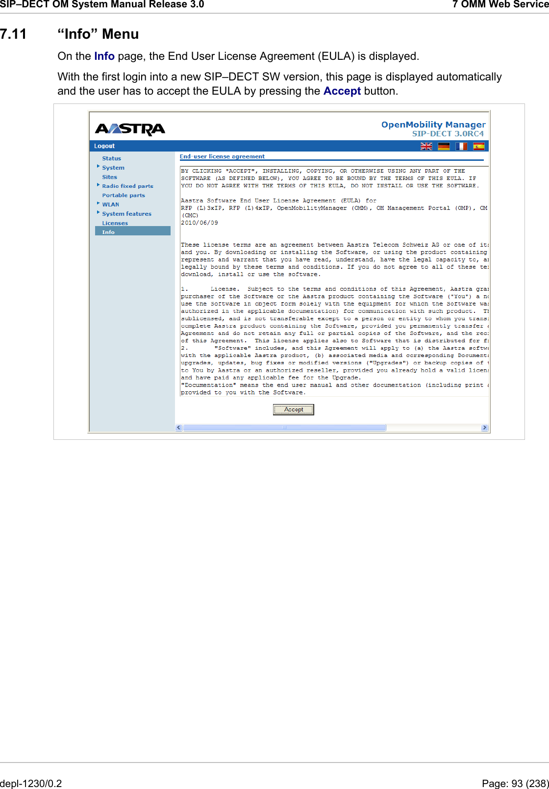
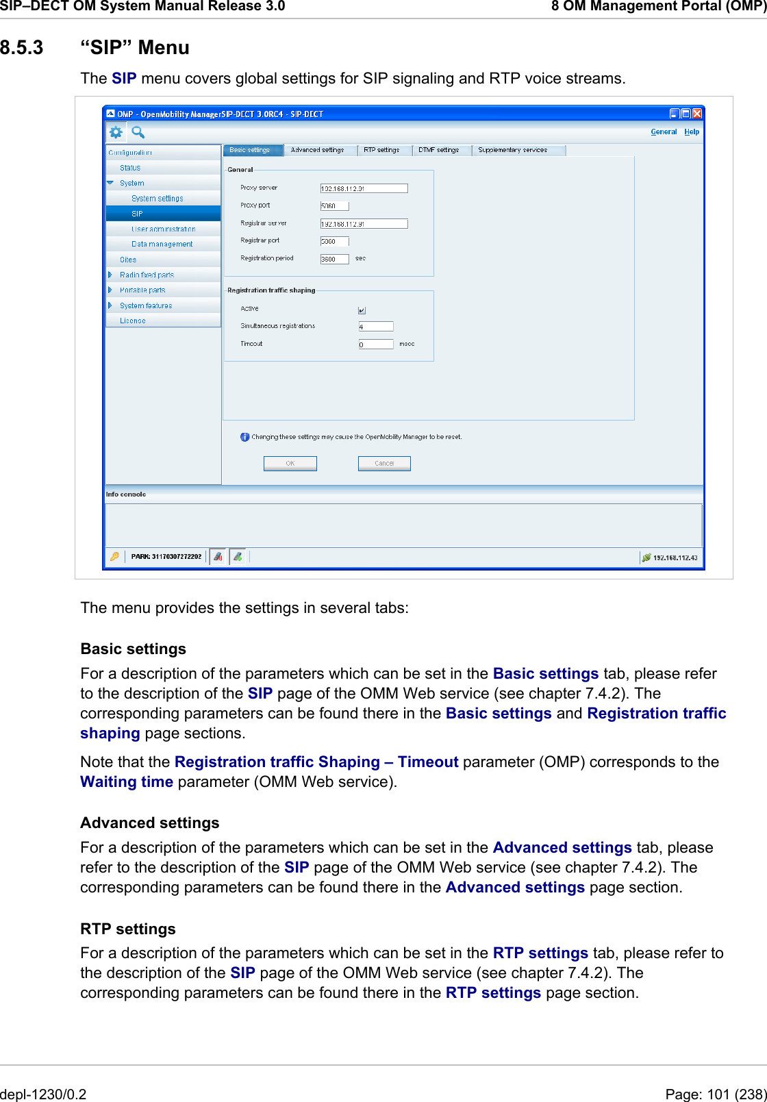
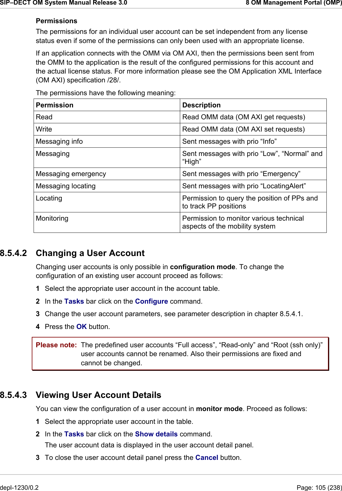
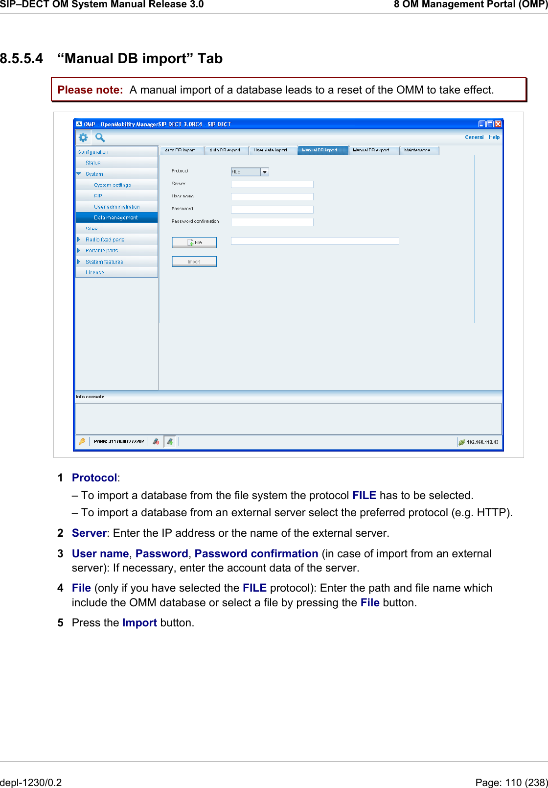
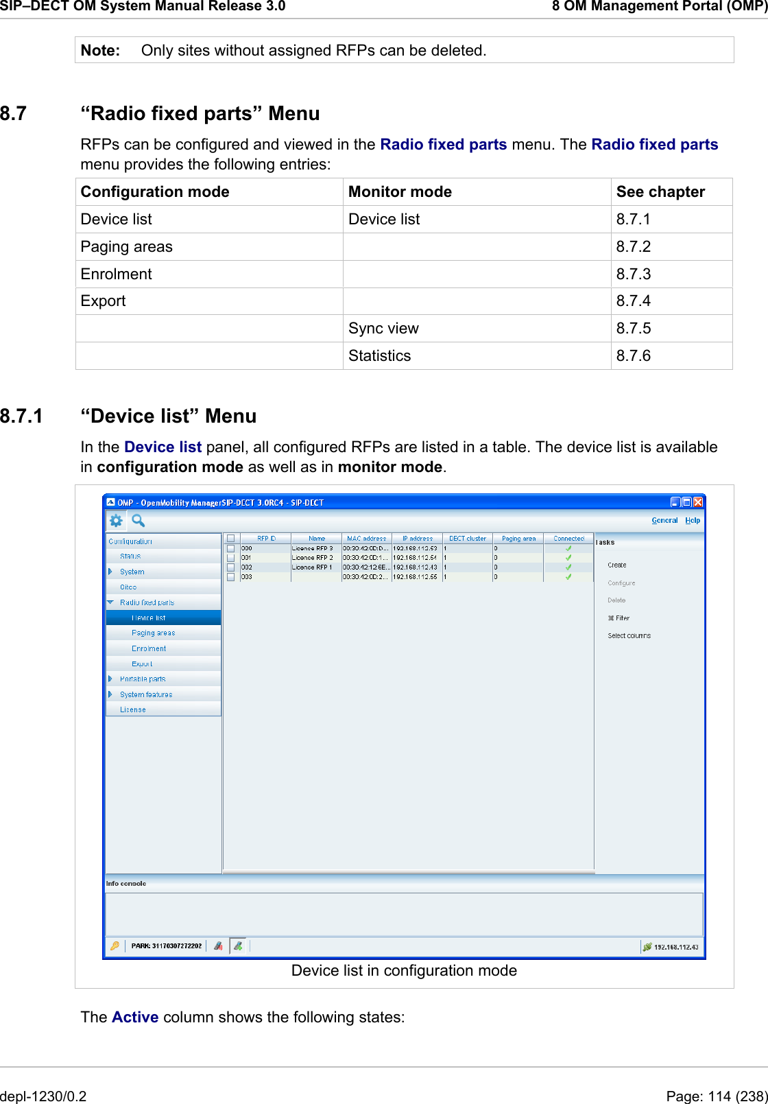
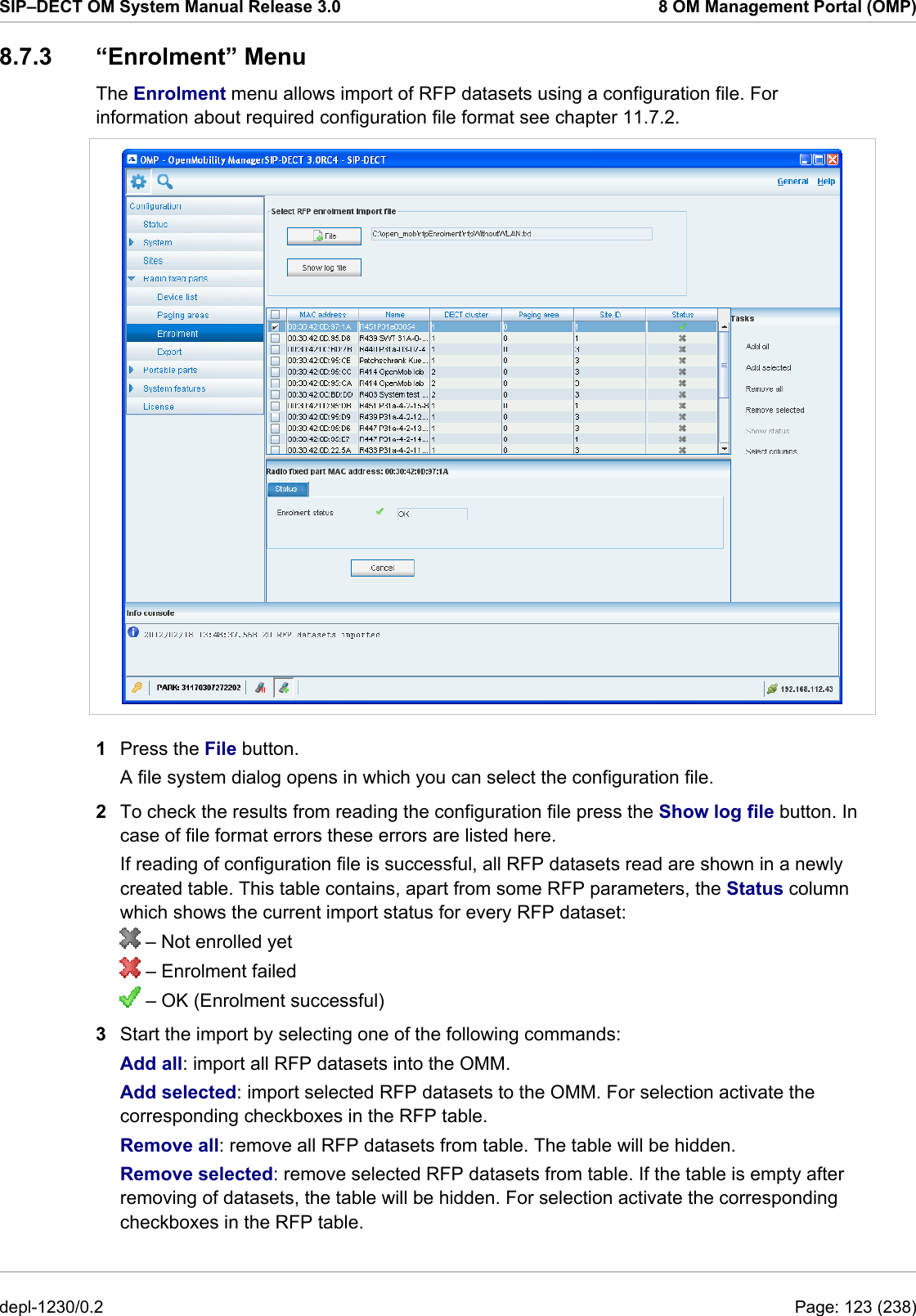
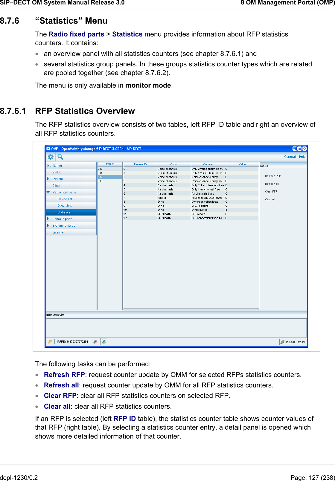
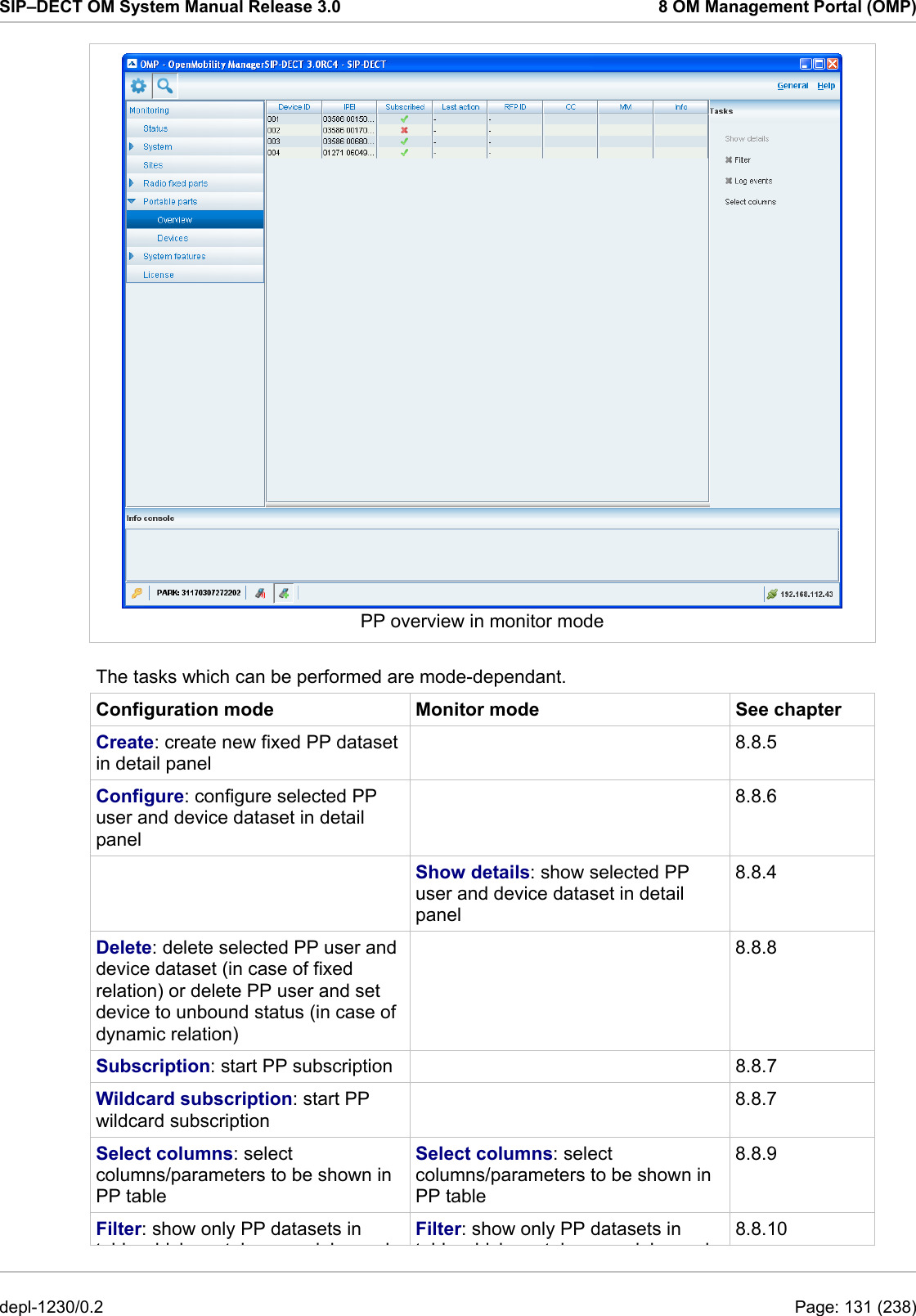
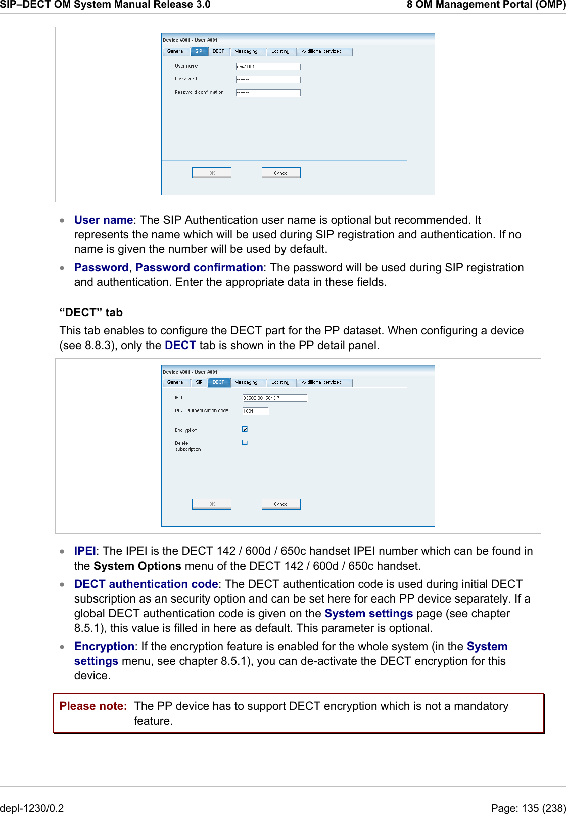
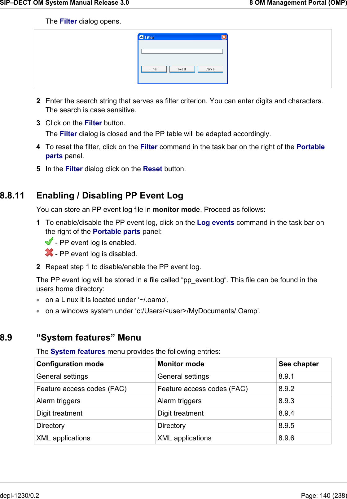
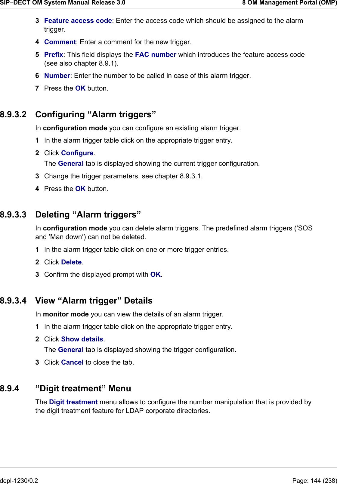
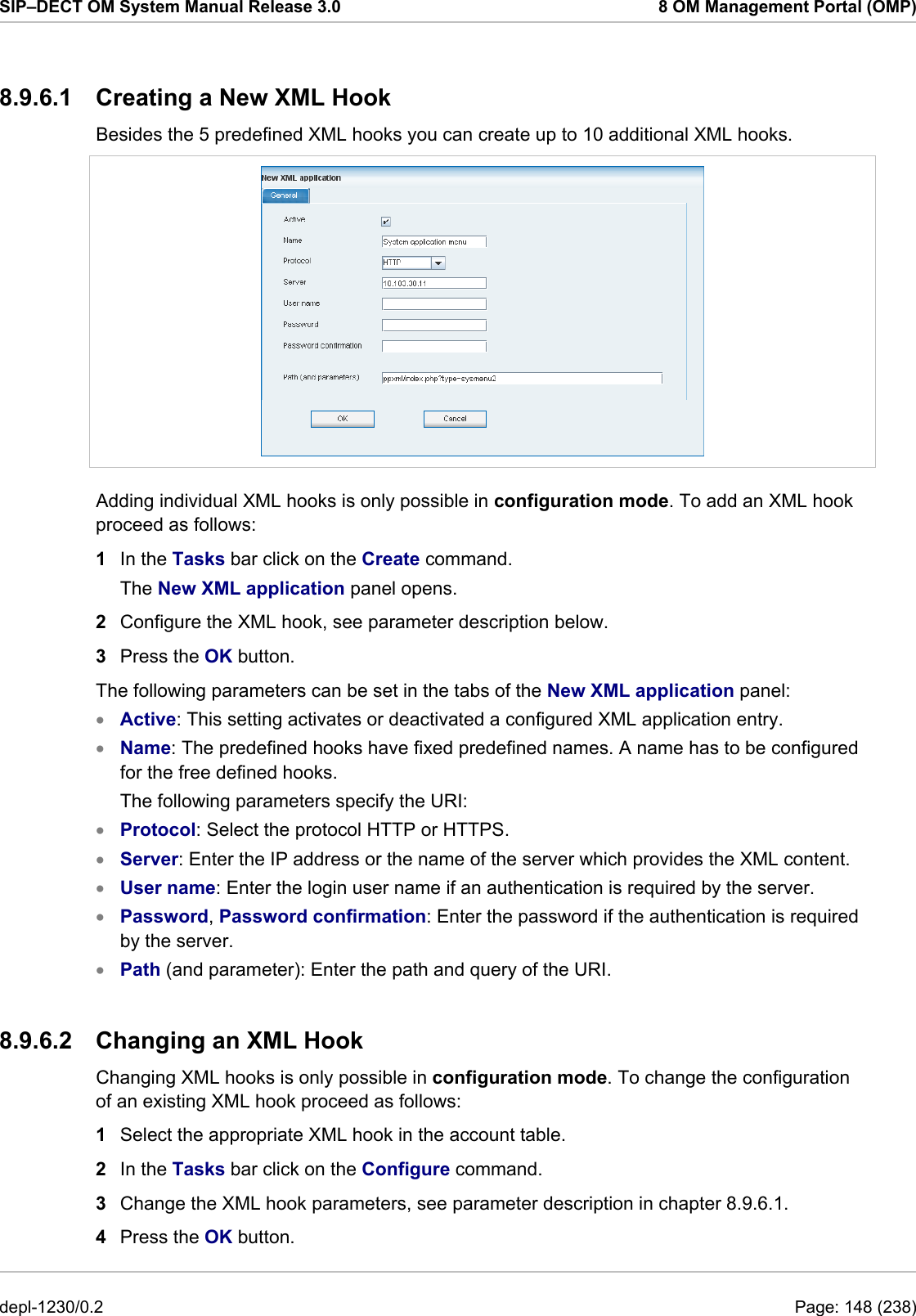
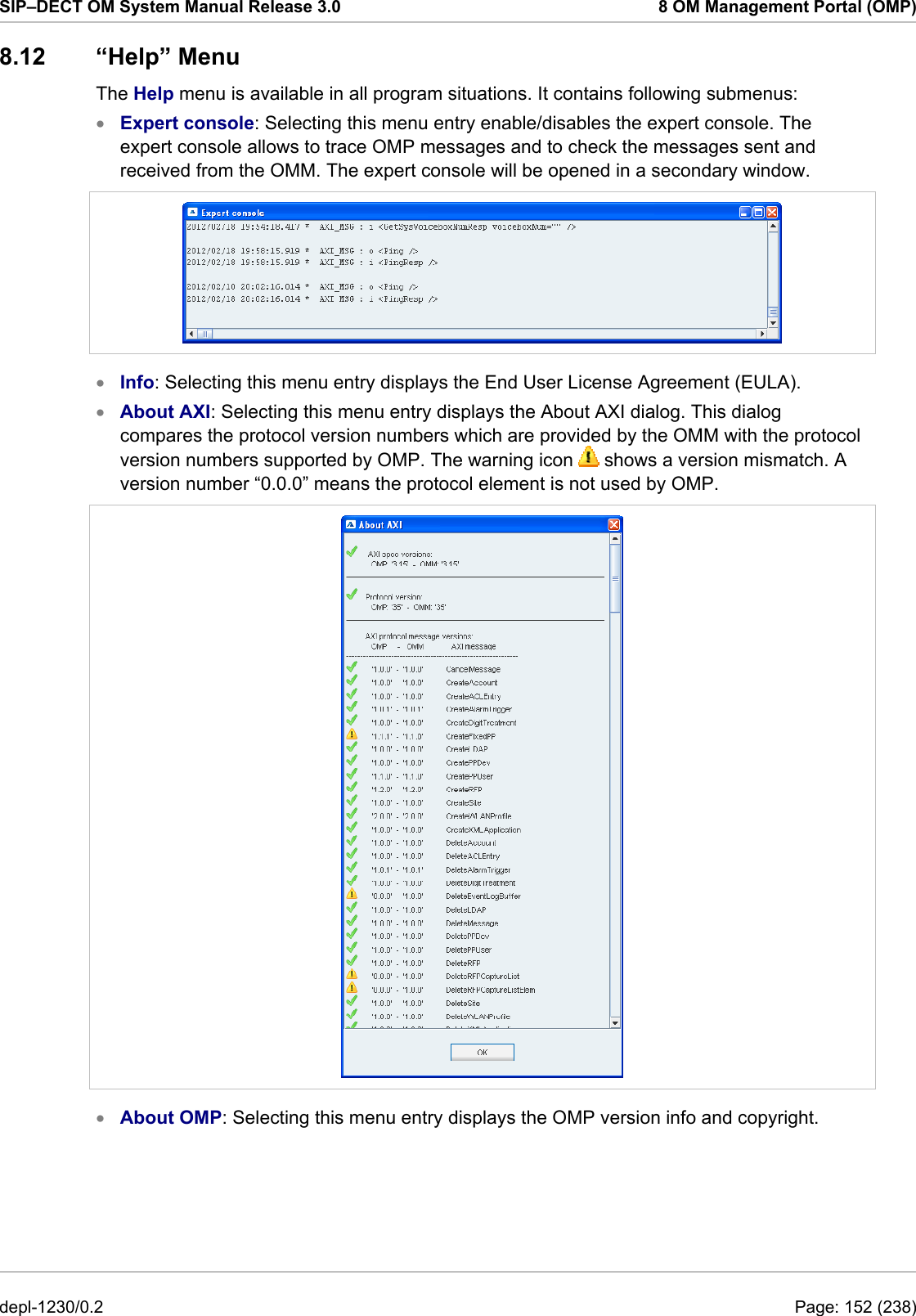
![SIP–DECT OM System Manual Release 3.0 8 OM Management Portal (OMP) In the Automatic DB import panel enter the following: 1 Startup only: Activate this option if the import should be started for an initial configuration. 2 Startup and periodically: If this option is activated, the OMM tries to import the configured database file during startup and at the configured time of day. 3 Time: Enter the time, the import should be started. Please note: An automatic database import at a configured time recommends the time synchronization with an NTP server. For NTP server configuration see chapter 9.5.4 and chapter 9.6. 4 Protocol: To import a database from an external server select the preferred protocol. The following protocols are supported: FTP, FTPS, HTTP, HTTPS, TFTP. 5 Server: Enter the IP address or the name of the external server. 6 User name, Password: If necessary, enter the account data of the server. 7 File: Enter the path and file name which include the OMM database. The database file for an automatic import has to be configured in an URL format like {ftp|ftps|http|https}://[[user:password@]server]/[directory/]file or tftp://[server]/[directory/]file.To be available at OMM startup time and to allow an initial configuration via automatic import, this URL has to be specified via DHCP (option 24, see chapter 9.5.4) or the OM Configurator (see chapter 9.6). If such a URL is given by DHCP depl-1230/0.2 Page: 107 (238)](https://usermanual.wiki/Mitel-Deutschland/68635RFP36U-01.UserManual-part2/User-Guide-1704945-Page-18.png)
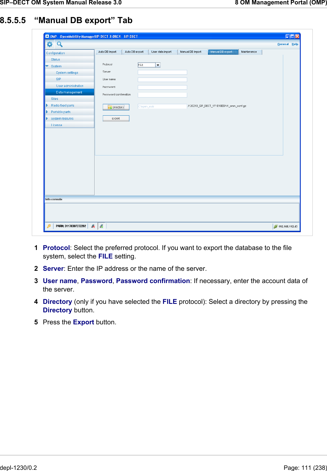

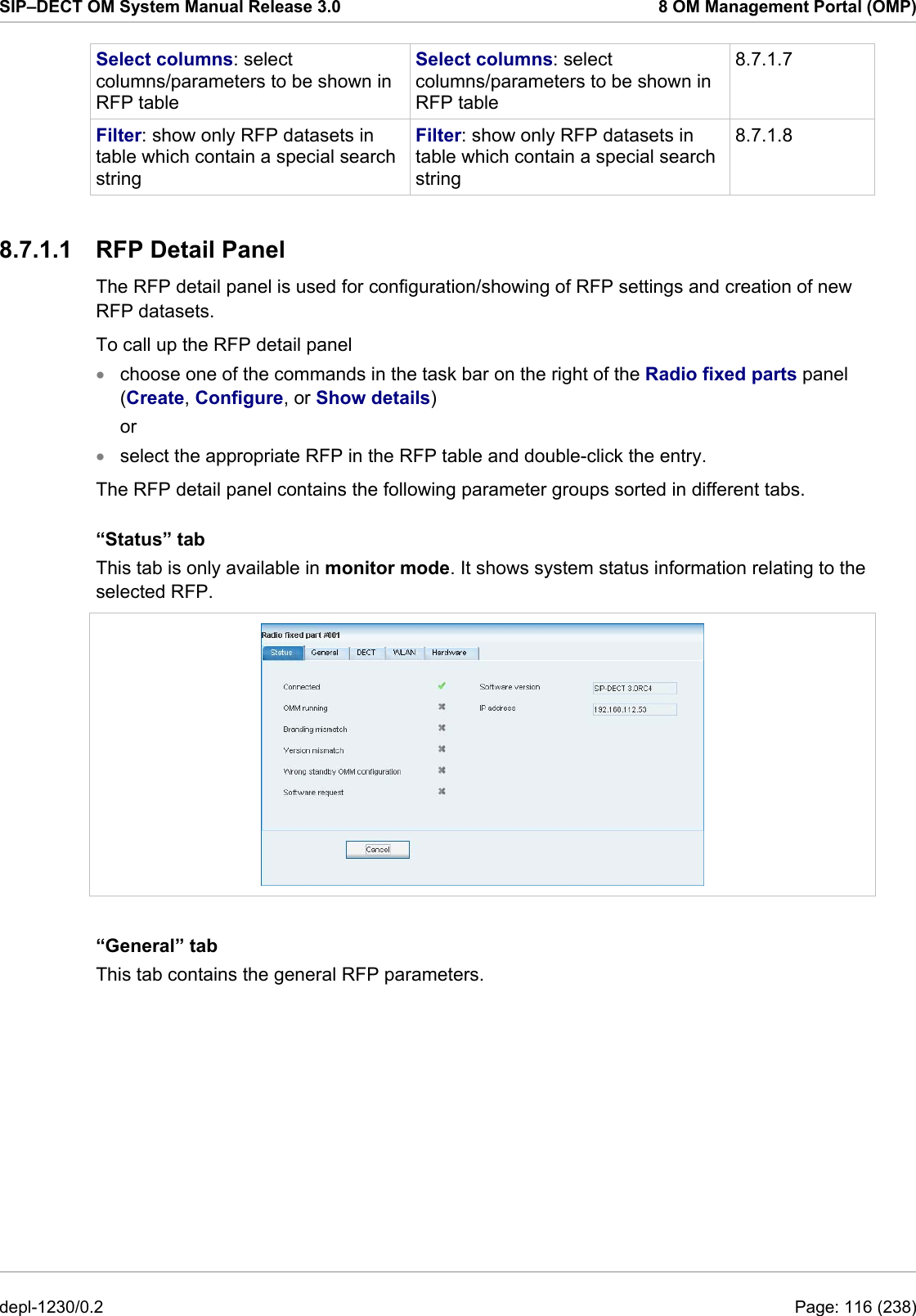
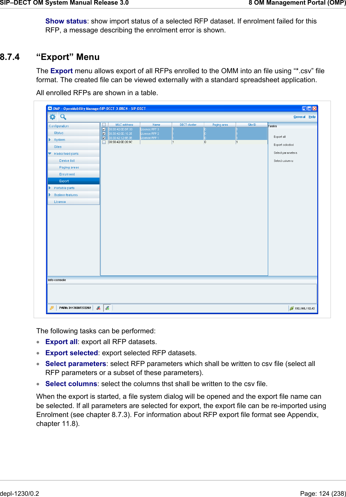
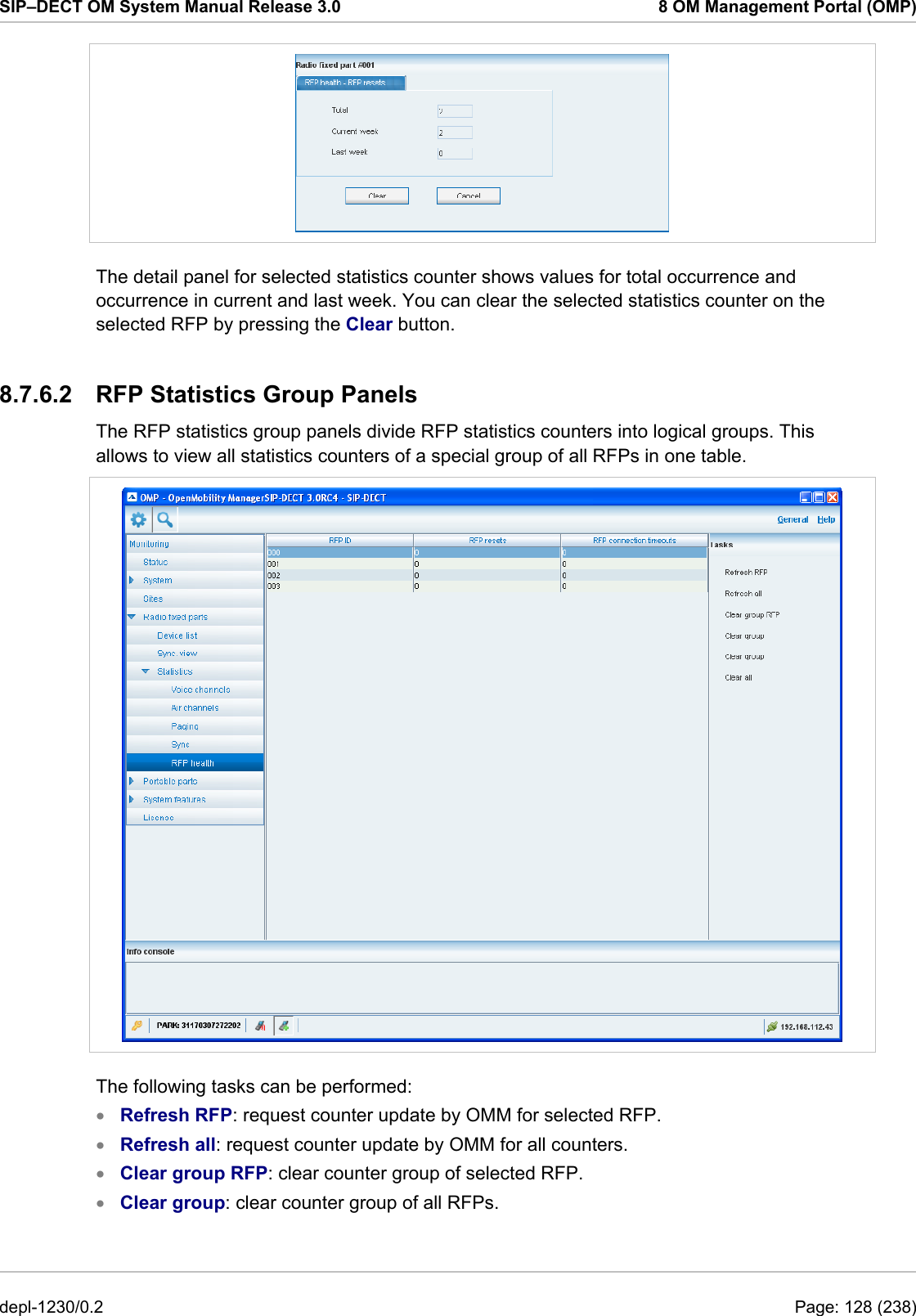
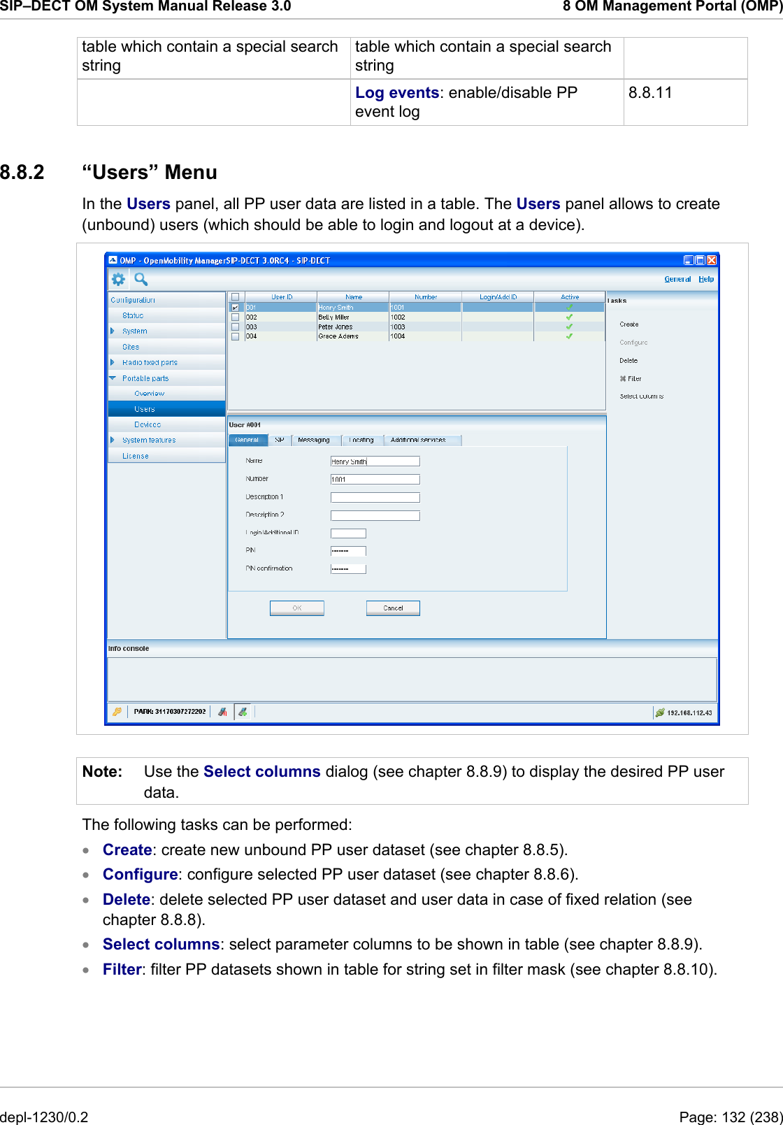
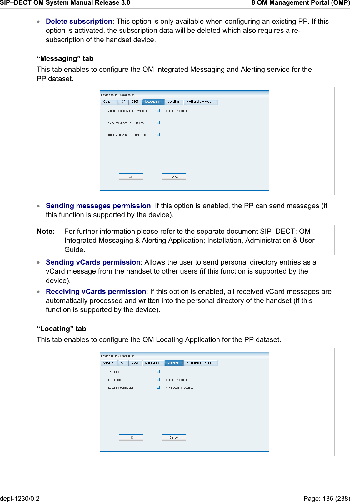
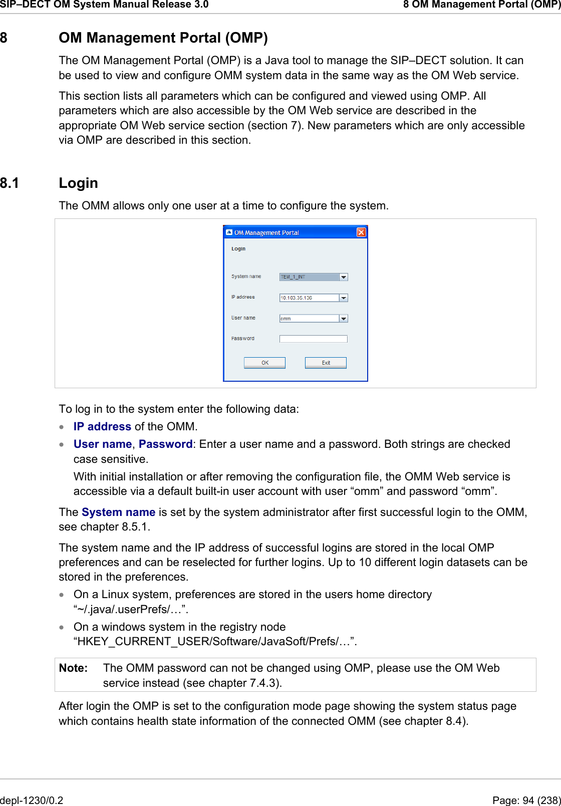
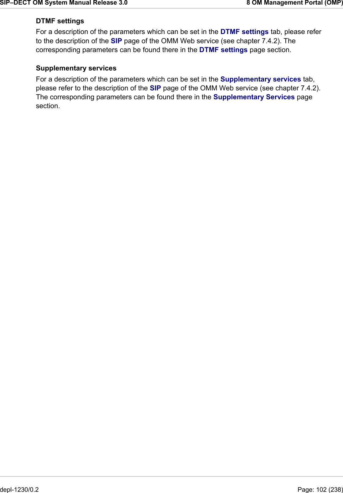
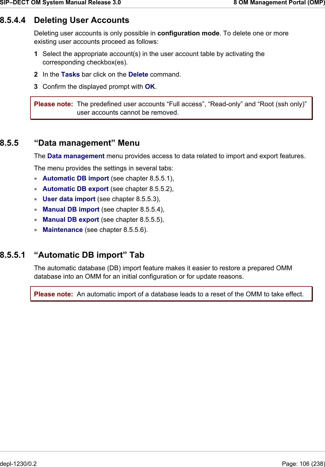
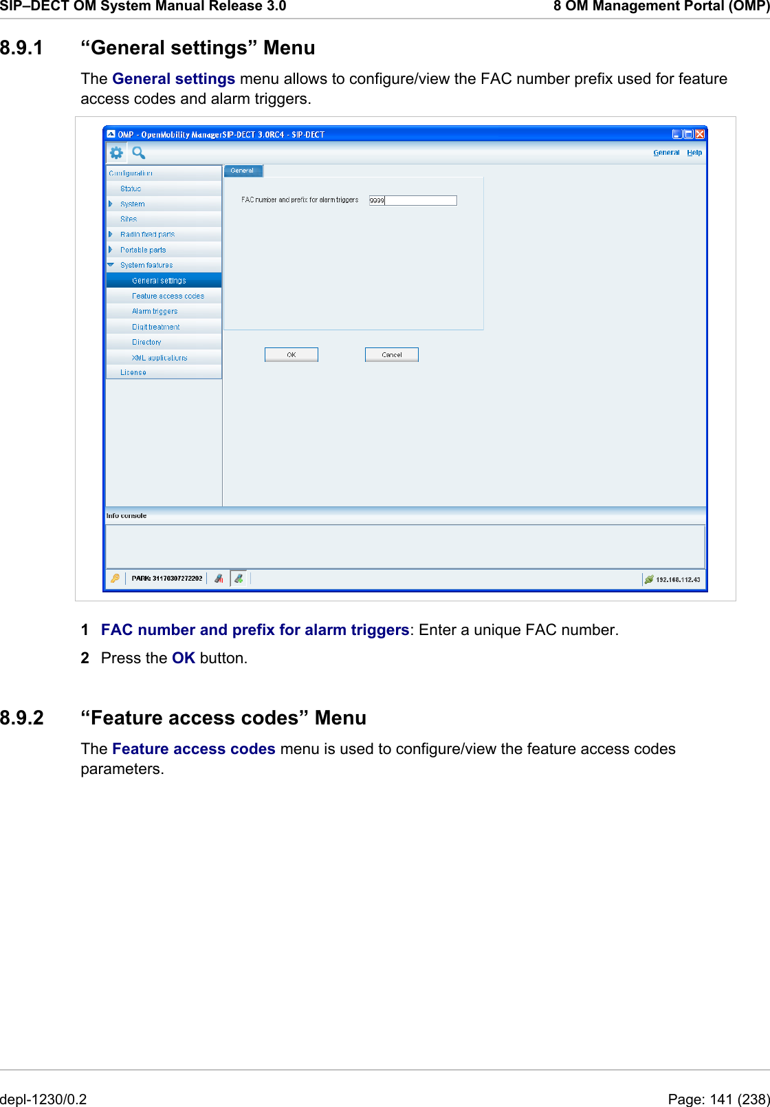
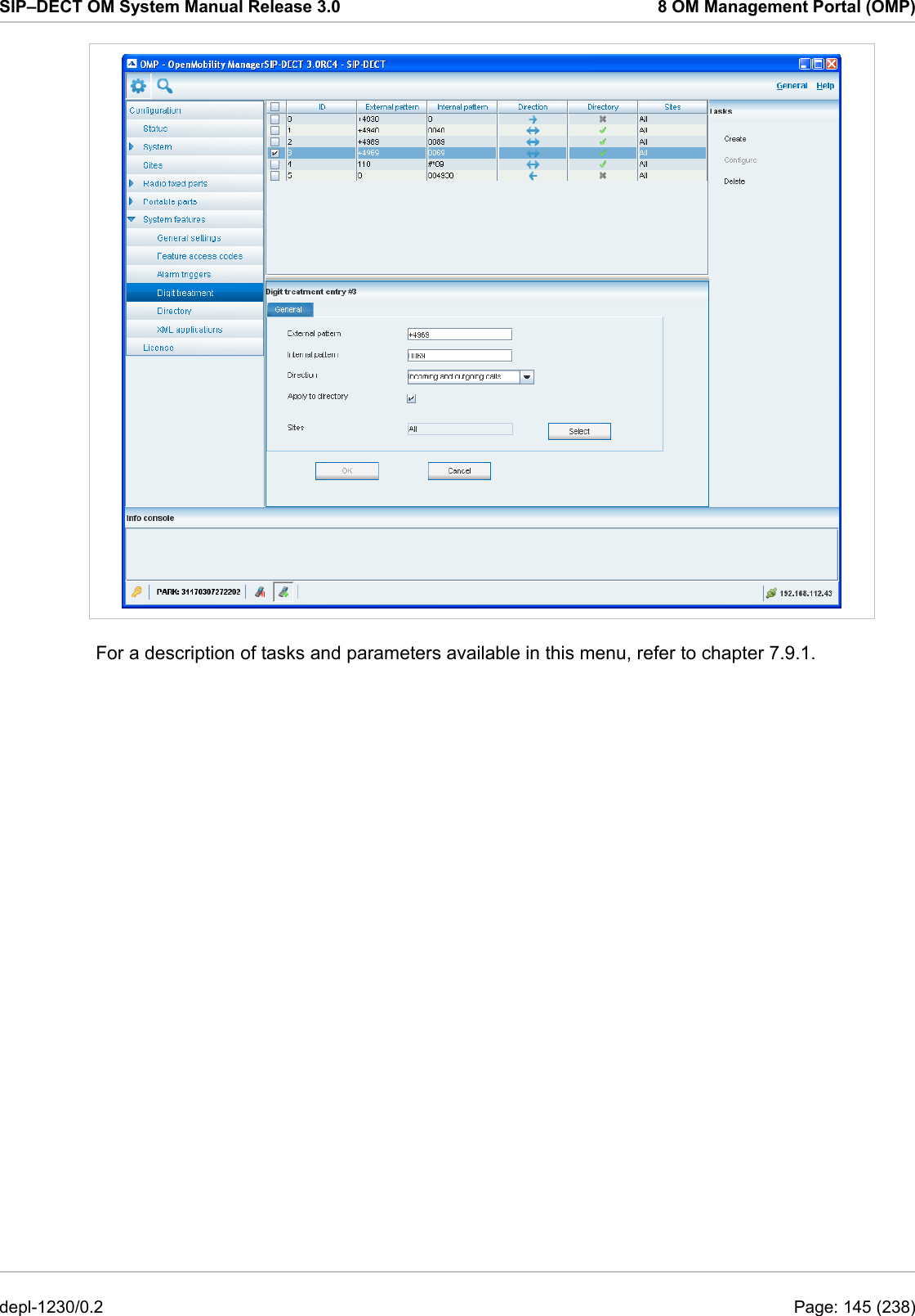
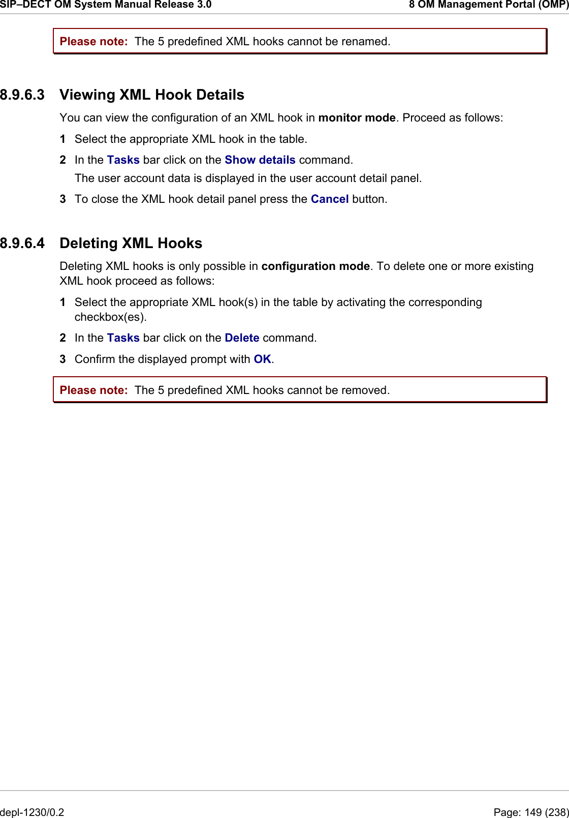
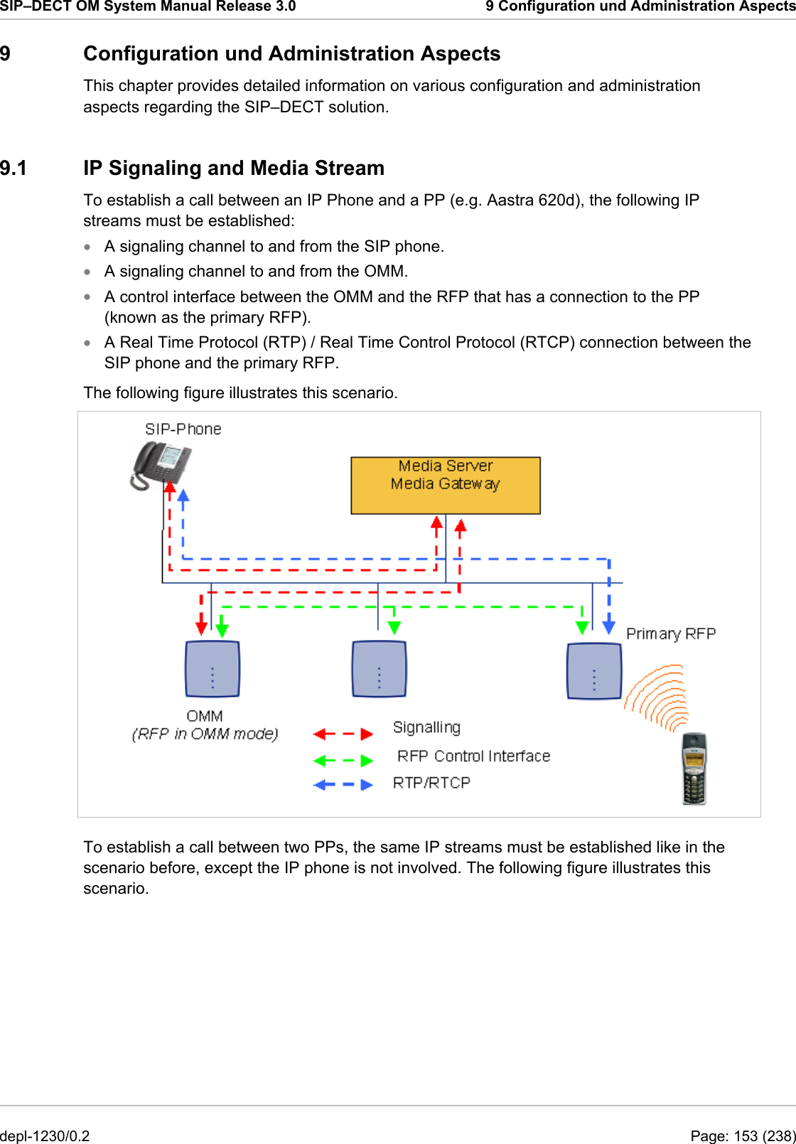
![SIP–DECT OM System Manual Release 3.0 8 OM Management Portal (OMP) 8.8.8 Deleting PP Datasets Deleting PP datasets is only possible in configuration mode. You can delete the fixed PP dataset (in case of fixed relation) or only the PP user data resp. the PP device data (in case of dynamic relation). To delete one or more existing PP datasets proceed as follows: 1 Select the appropriate PP dataset(s) in the PP table by activating the corresponding checkbox(es). 2 In the task bar on the right of the Portable parts panel click on the Delete command. – In the Overview submenu the whole PP dataset will be deleted. – In the Users submenu only the PP user data will be deleted. – In the Devices submenu only the PP device data will be deleted. The Delete [xxx] dialog opens showing a confirmation prompt. 3 Confirm the displayed prompt with OK. 8.8.9 Selecting Columns You can adapt the parameters shown in the PP table to your needs: 1 In the task bar on the right of the Portable parts panel click on the Select columns command. The Select columns dialog opens. 2 Select the columns that shall be shown by activating the appropriate checkboxes. 3 Click the OK button. The PP table will be adapted accordingly. 8.8.10 Filtering PP Table You can filter the list of PP datasets shown in the PP table by using a filter. 1 In the task bar on the right of the Portable parts panel click on the Filter command. depl-1230/0.2 Page: 139 (238)](https://usermanual.wiki/Mitel-Deutschland/68635RFP36U-01.UserManual-part2/User-Guide-1704945-Page-50.png)
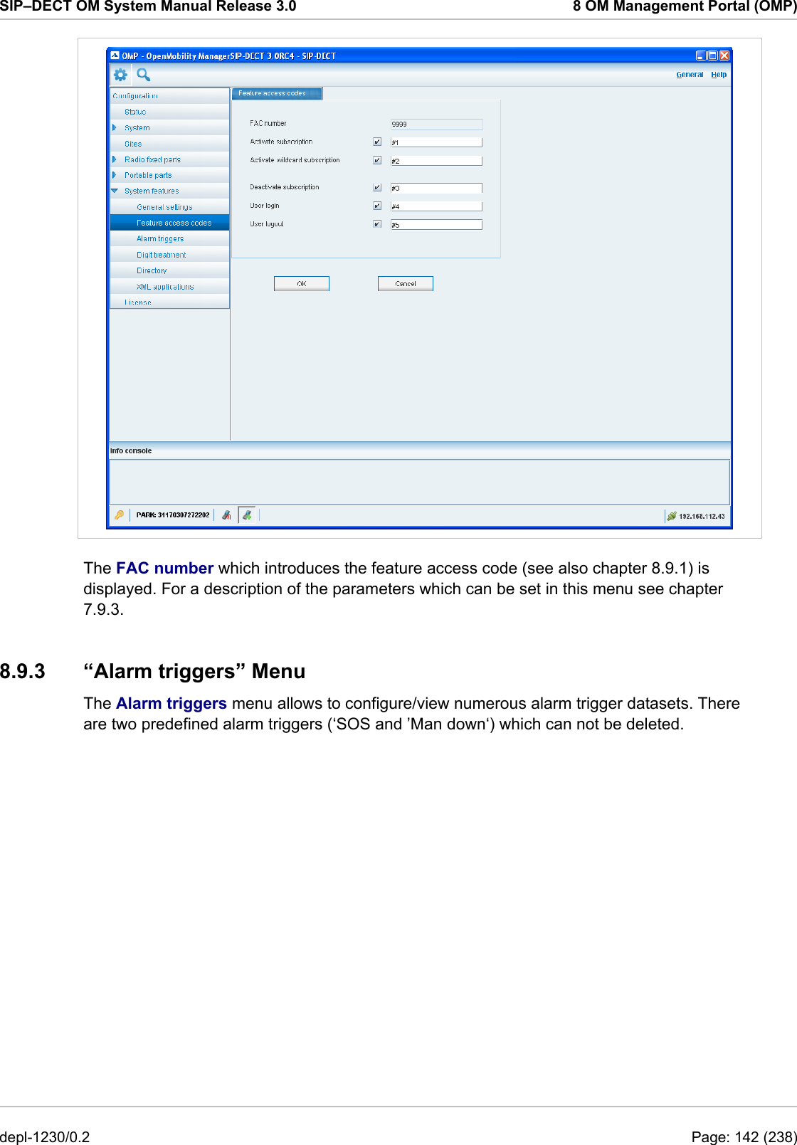
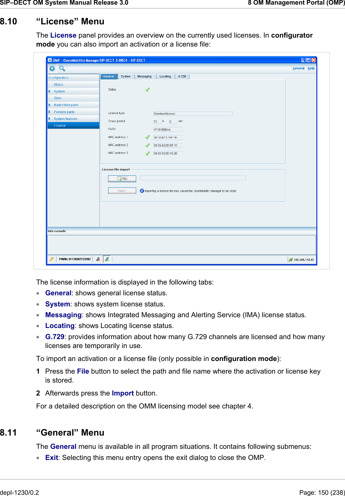
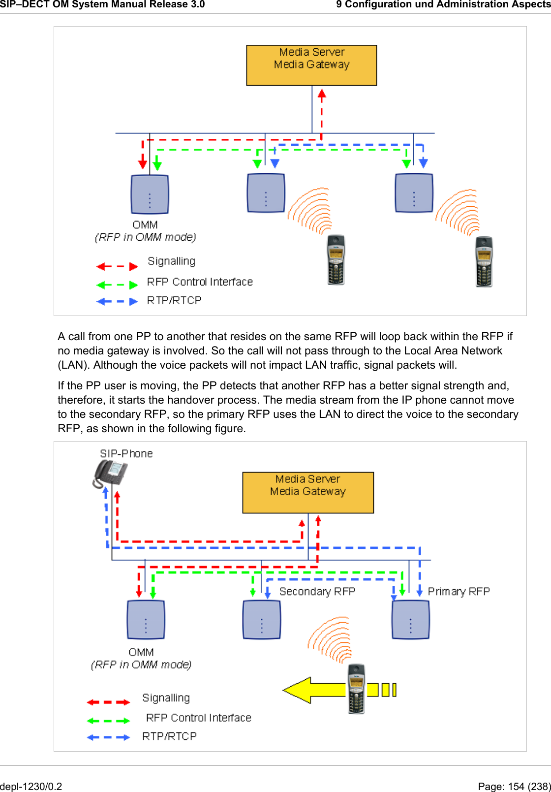
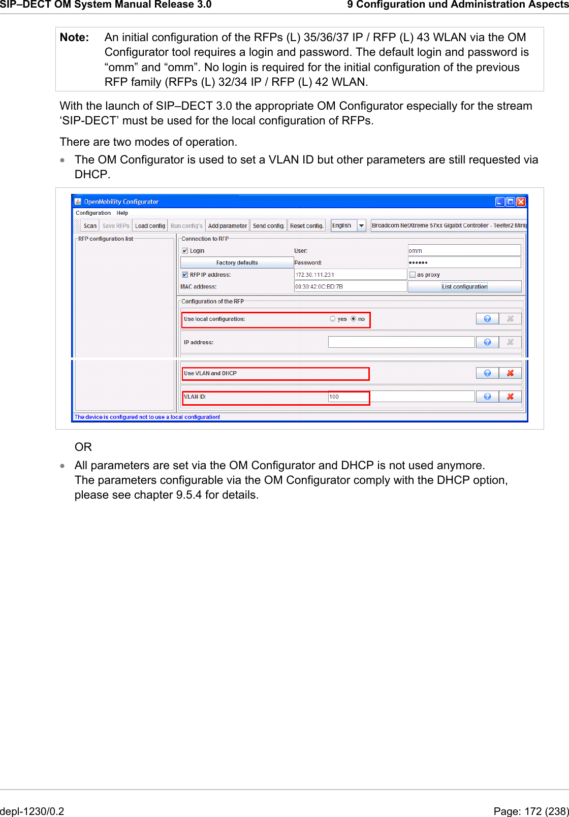
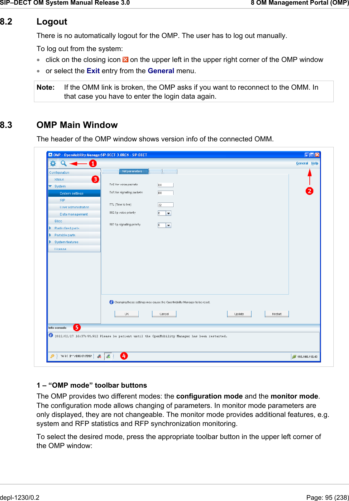
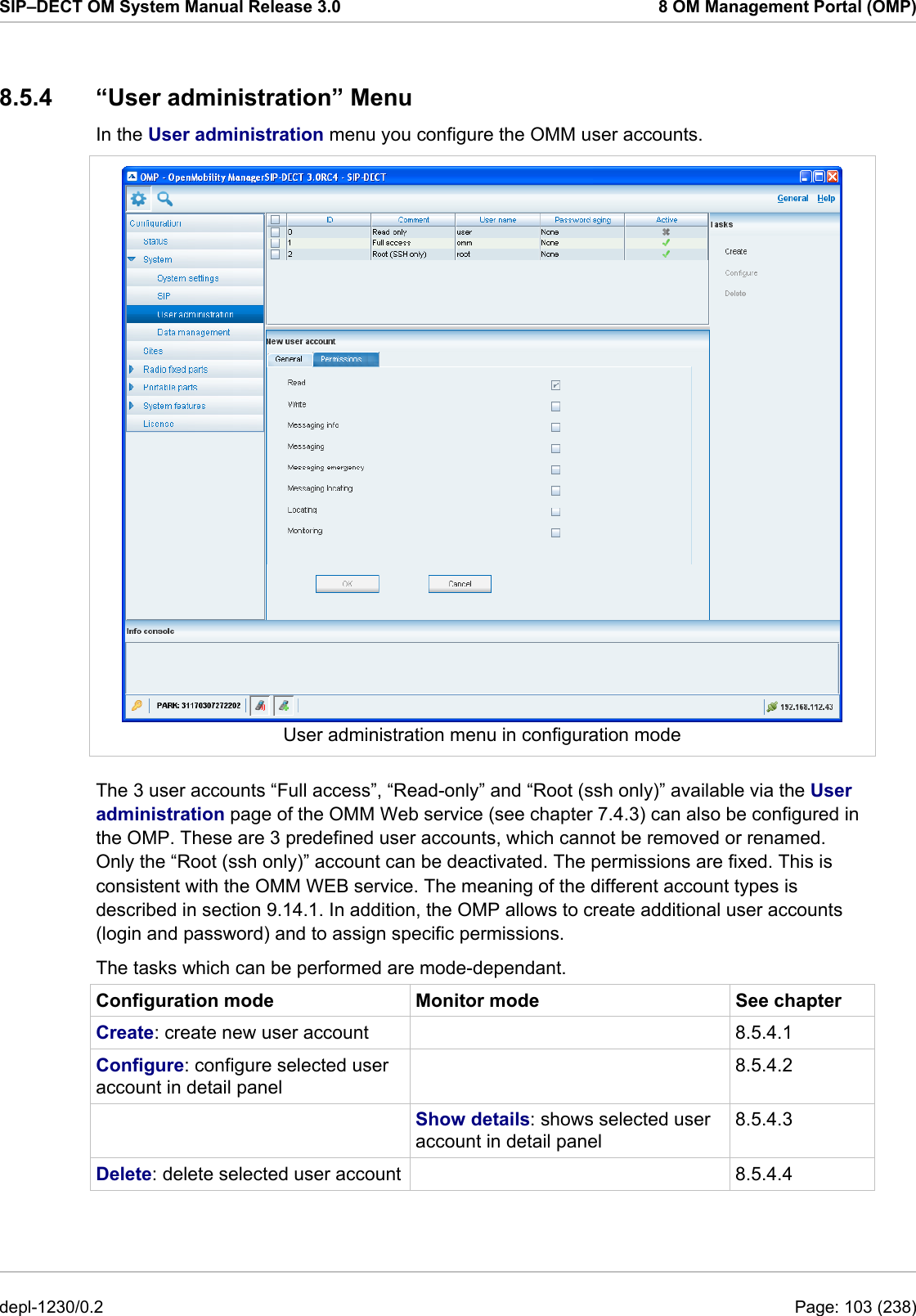
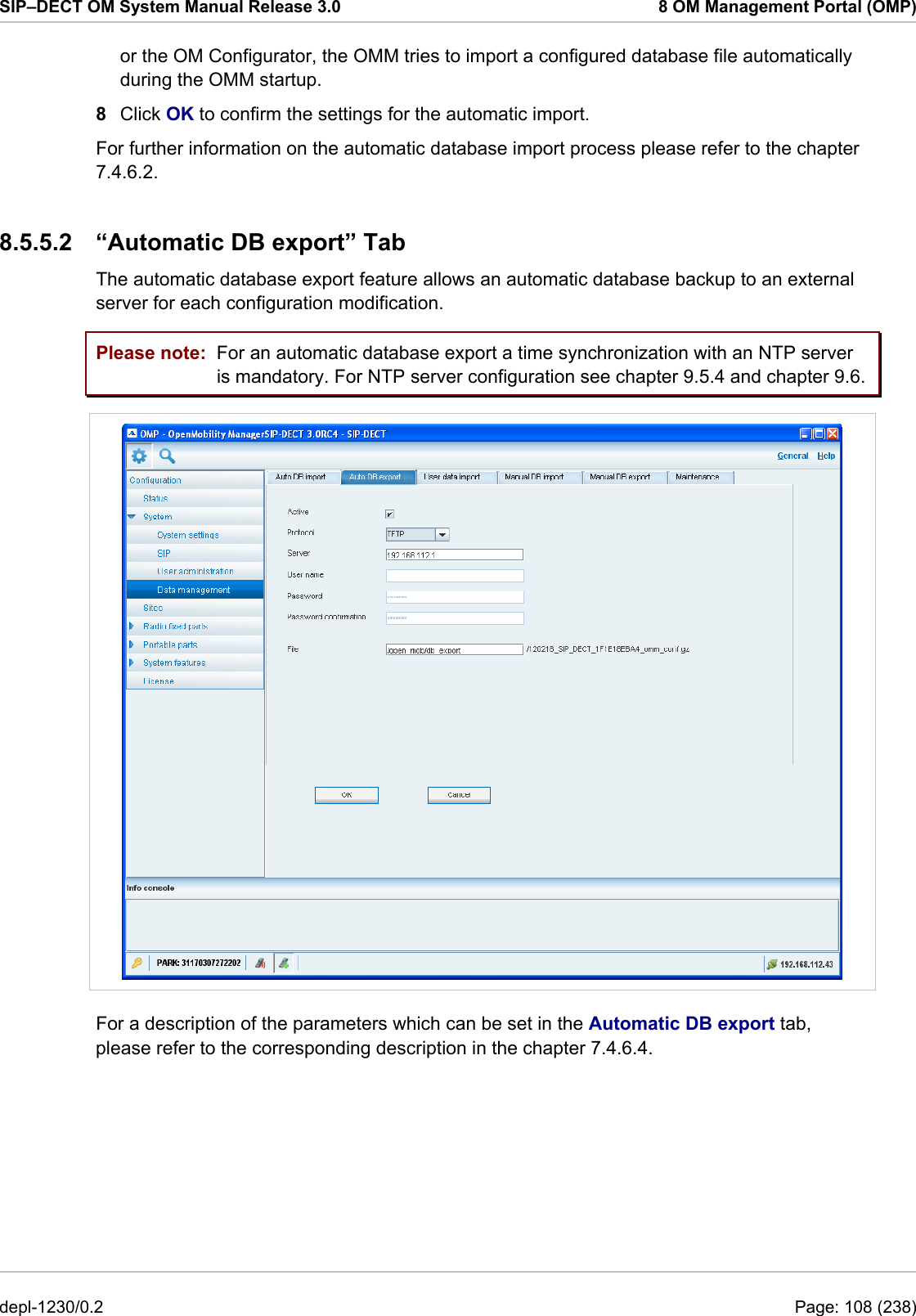
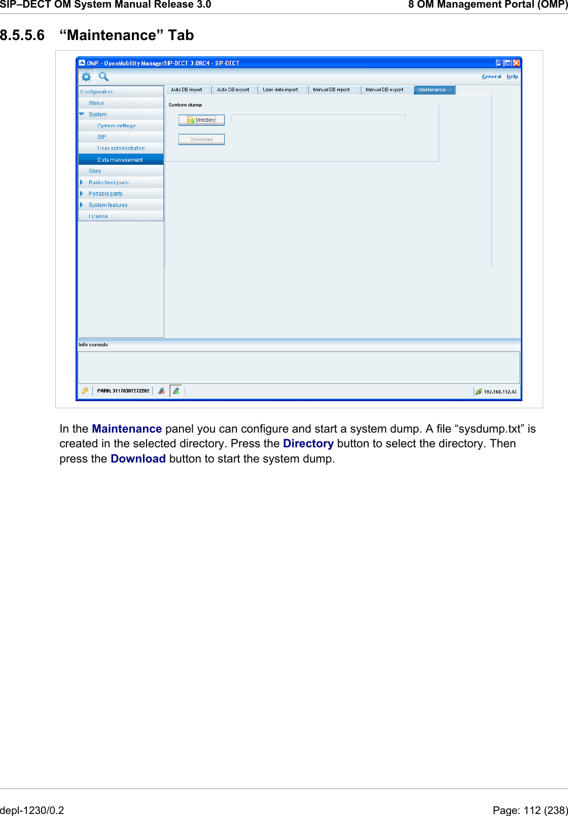
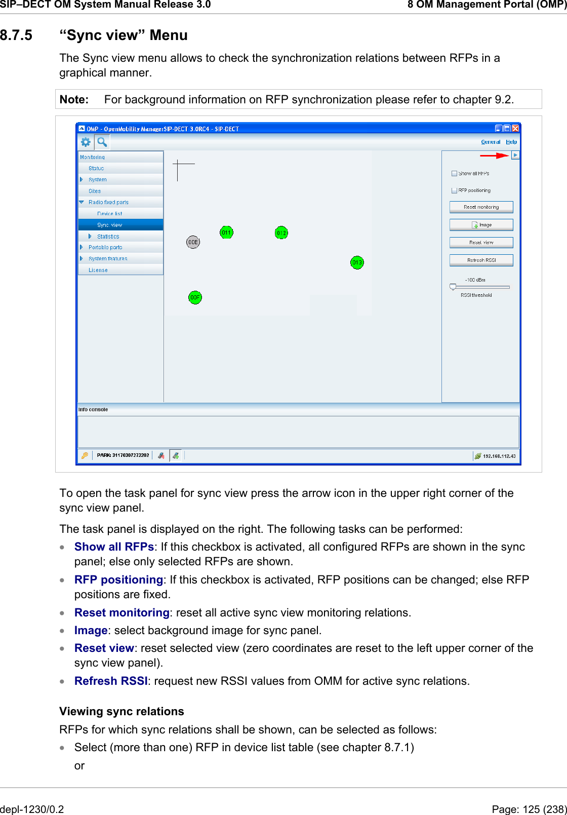
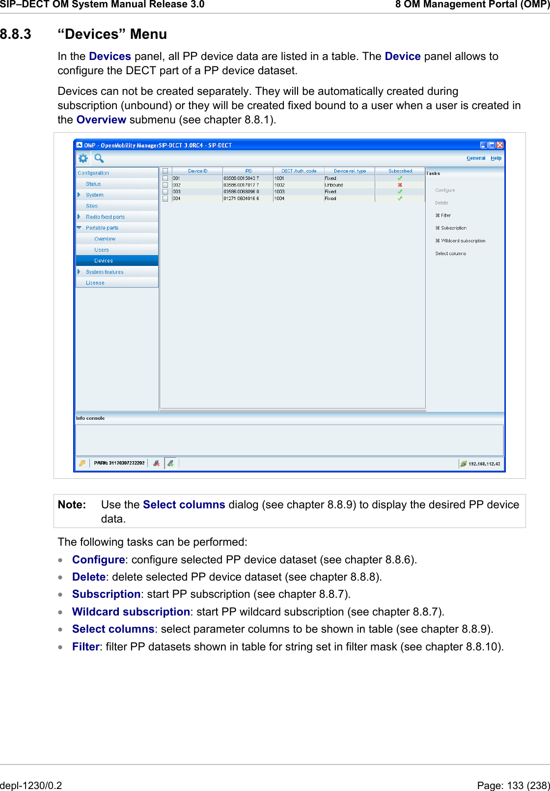
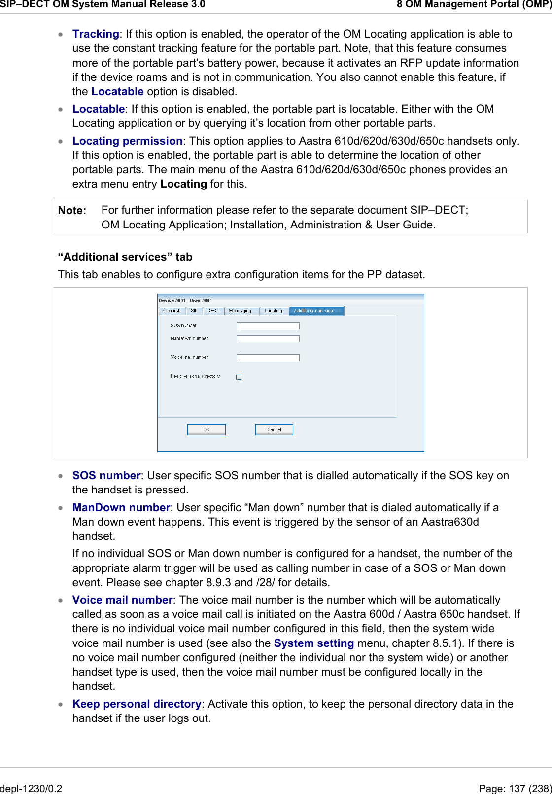
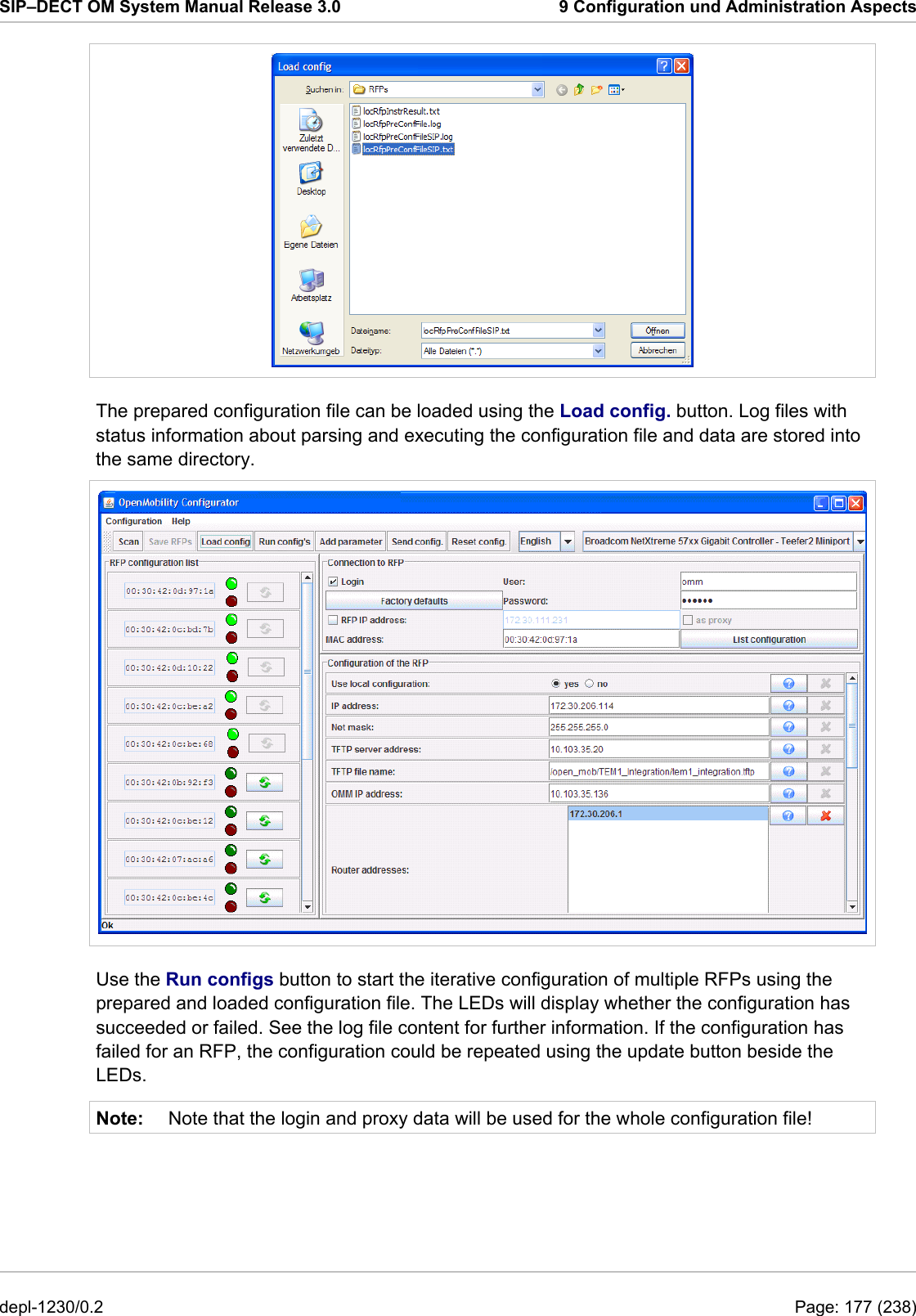
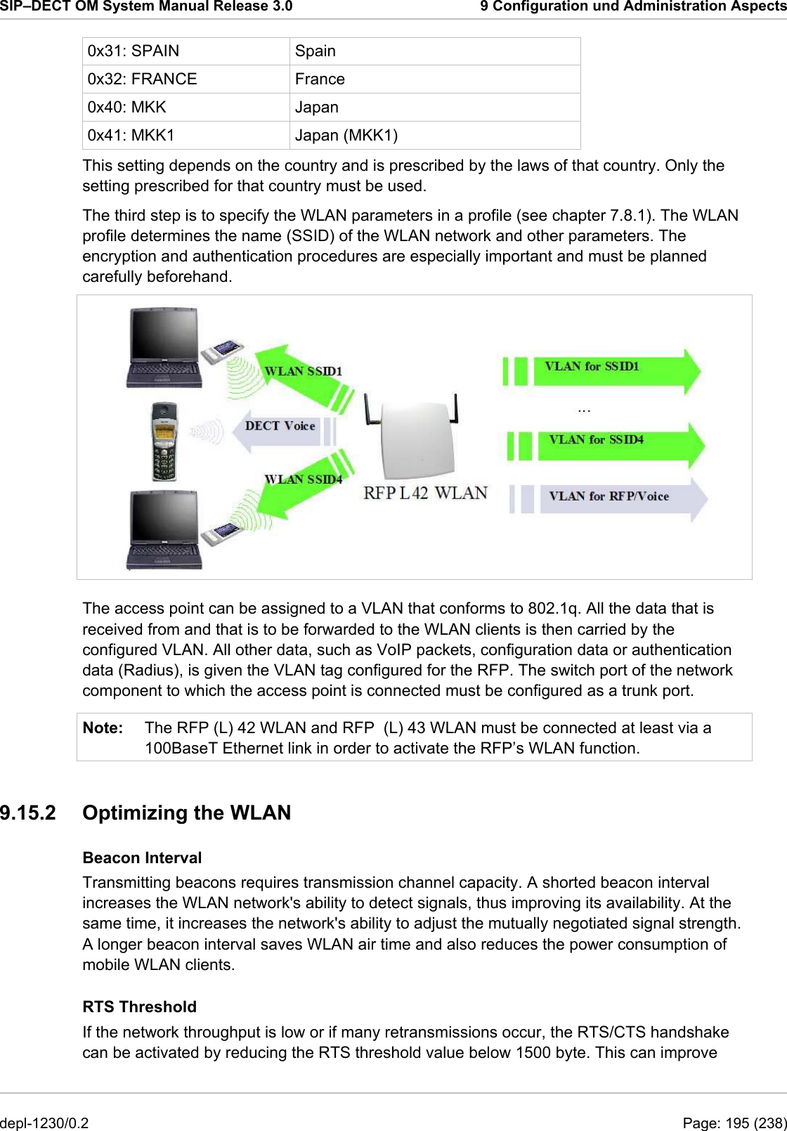
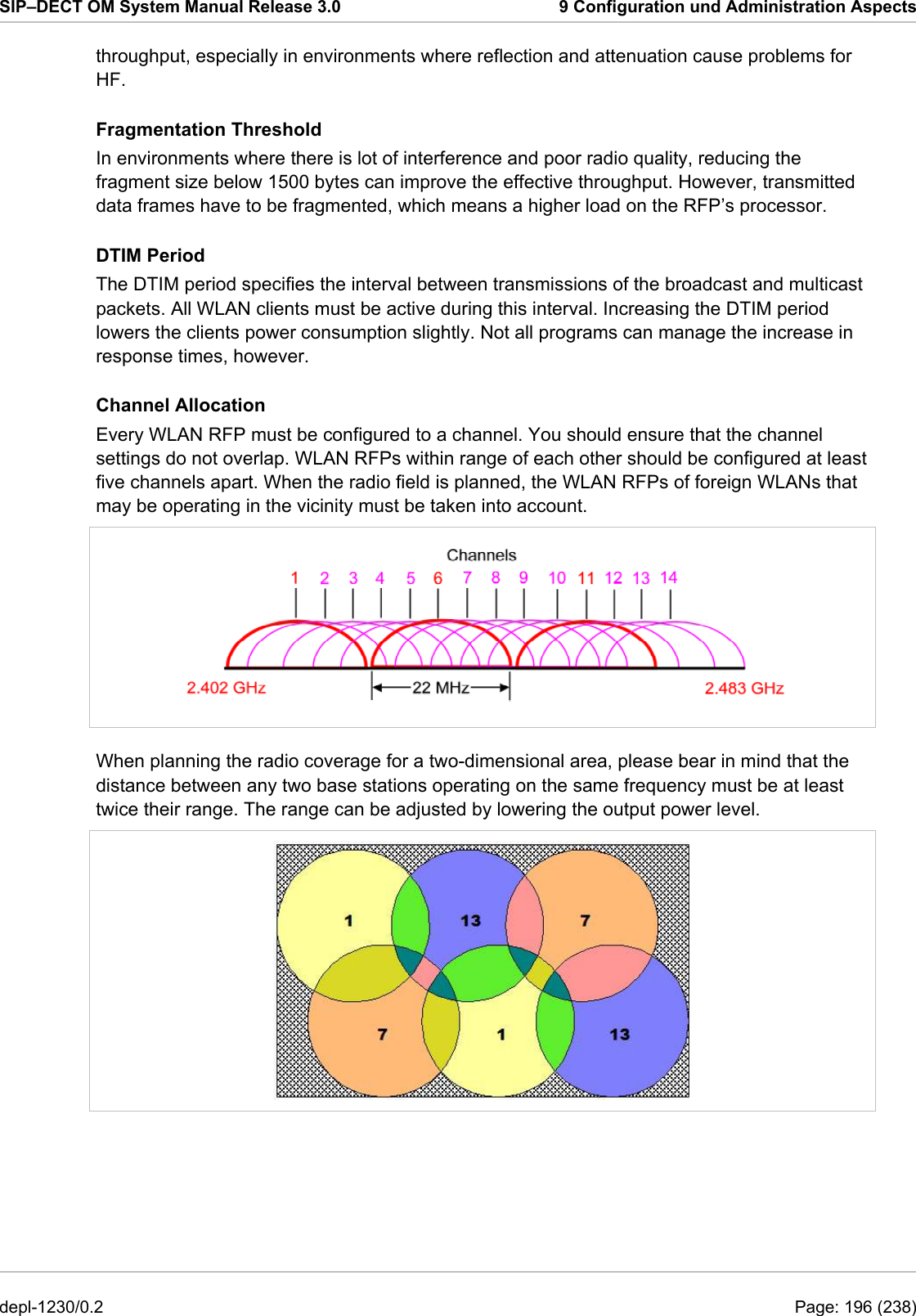
![SIP–DECT OM System Manual Release 3.0 9 Configuration und Administration Aspects chapter 8.5.5.1) Configuration file server optional URL of a server with configuration files (ipdect.cfg|<mac>.cfg) alternatively/in addition to OM Configurator settings. Syntax: {ftp|ftps|http|https}://[user:password@]server/[directory/] or tftp://server/[directory/] Core dump* optional In case of an system error the RFP creates core dump files and transfers them using TFTP to the folder configured in the TFTP file name. * can not be set via DHCP The configuration can only be set after powering up or at the retry phase (LED flashing 0.25 Hz) or in kernel mode, please see chapter 9.5 for details. The OM Configurator tool waits 2 seconds and retries transmitting the data 3 times. If you want to read the configuration parameters from an RFP, set the MAC address and the IP address additionally and press the List configuration button. All parameters will be listed in the OM Configurator tool. Press the Reset configuration button to clean all input fields and additional parameters. Since the OpenMobility version 1.5, login data can be used to prevent against unauthorized configuration changes. If authorization is used, mark the Login checkbox and enter the user name and the password into the fields User and Password. This OM Configurator is backward compatible to previous OpenMobility versions without login support. A forgotten password could not be recovered but deleted using the Factory defaults button. Send the displayed cookie to the OpenMobility manufacturer support. After receiving the password reset key from the support, enter it into the Enter reset key dialog. This will delete the complete local configurations from the internal flash memory of the RFP, too! Please note: With the password reset all local configurations inclusively possible existing OpenMobility configurations will be deleted. An RFP outside the local LAN segment could also work as proxy. Mark the as proxy checkbox to enable this functionality. Then the MAC address will be used to address an RFP in the LAN segment of the proxy RFP. Scanning for available RFPs and configuration of multiple RFPs via a configuration file could be used also with the proxy mechanism. depl-1230/0.2 Page: 175 (238)](https://usermanual.wiki/Mitel-Deutschland/68635RFP36U-01.UserManual-part2/User-Guide-1704945-Page-86.png)
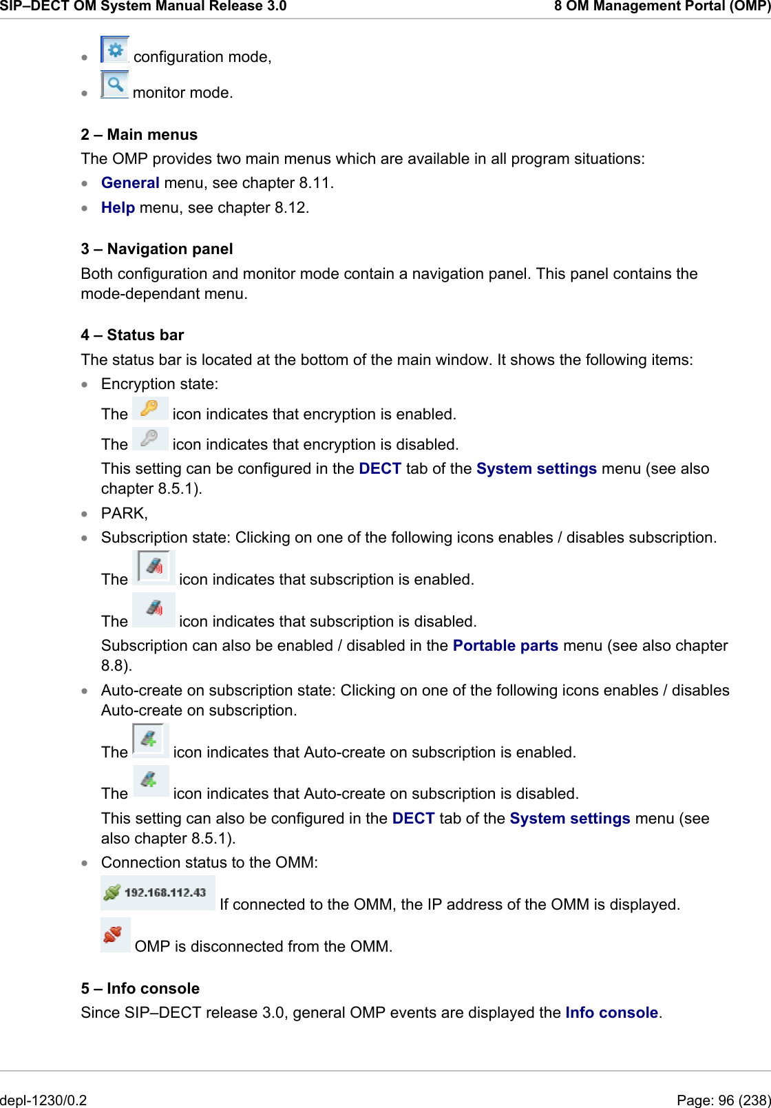
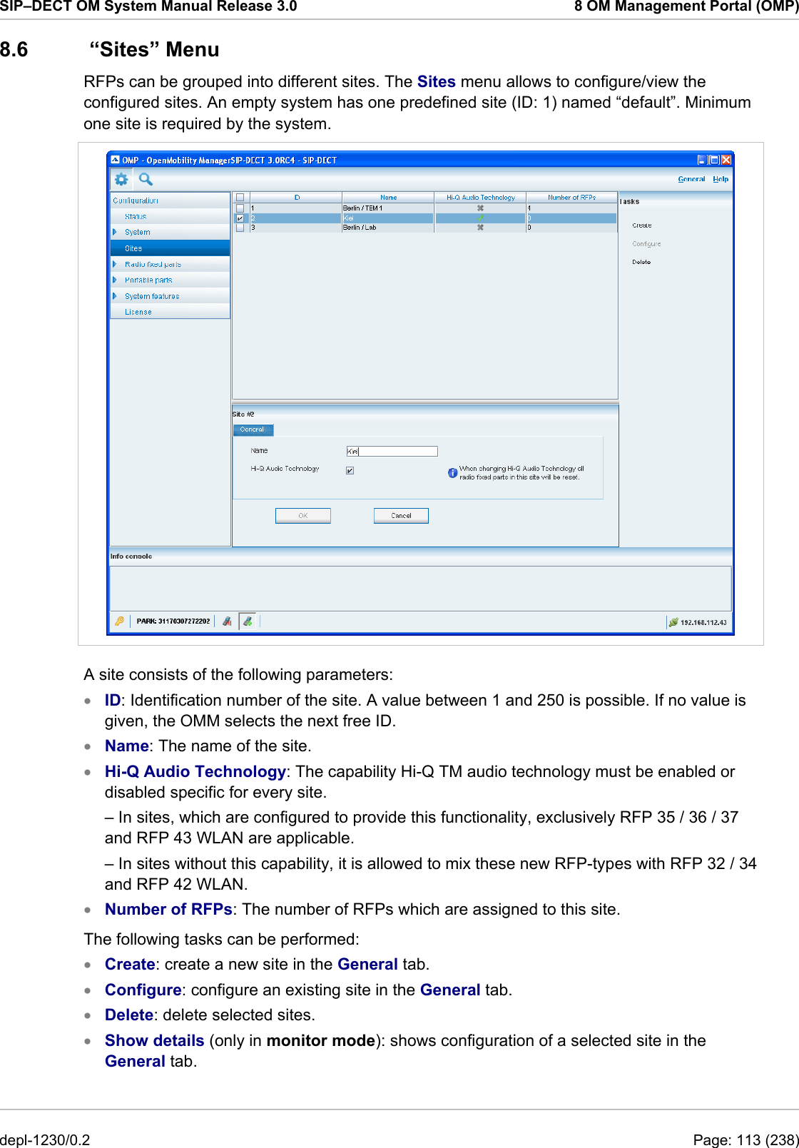
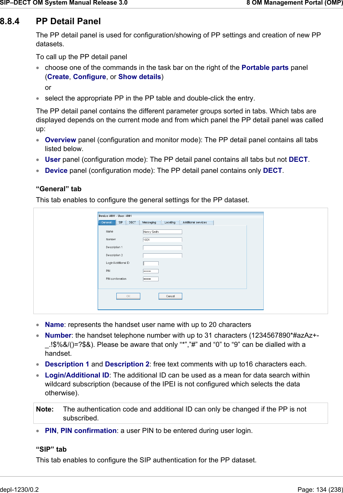
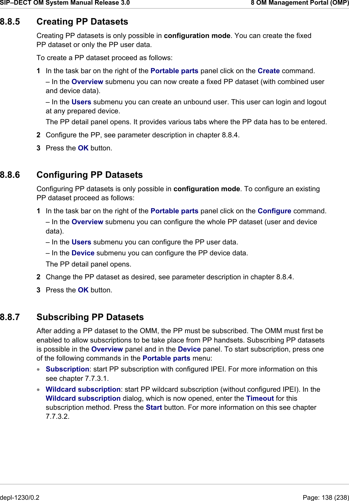
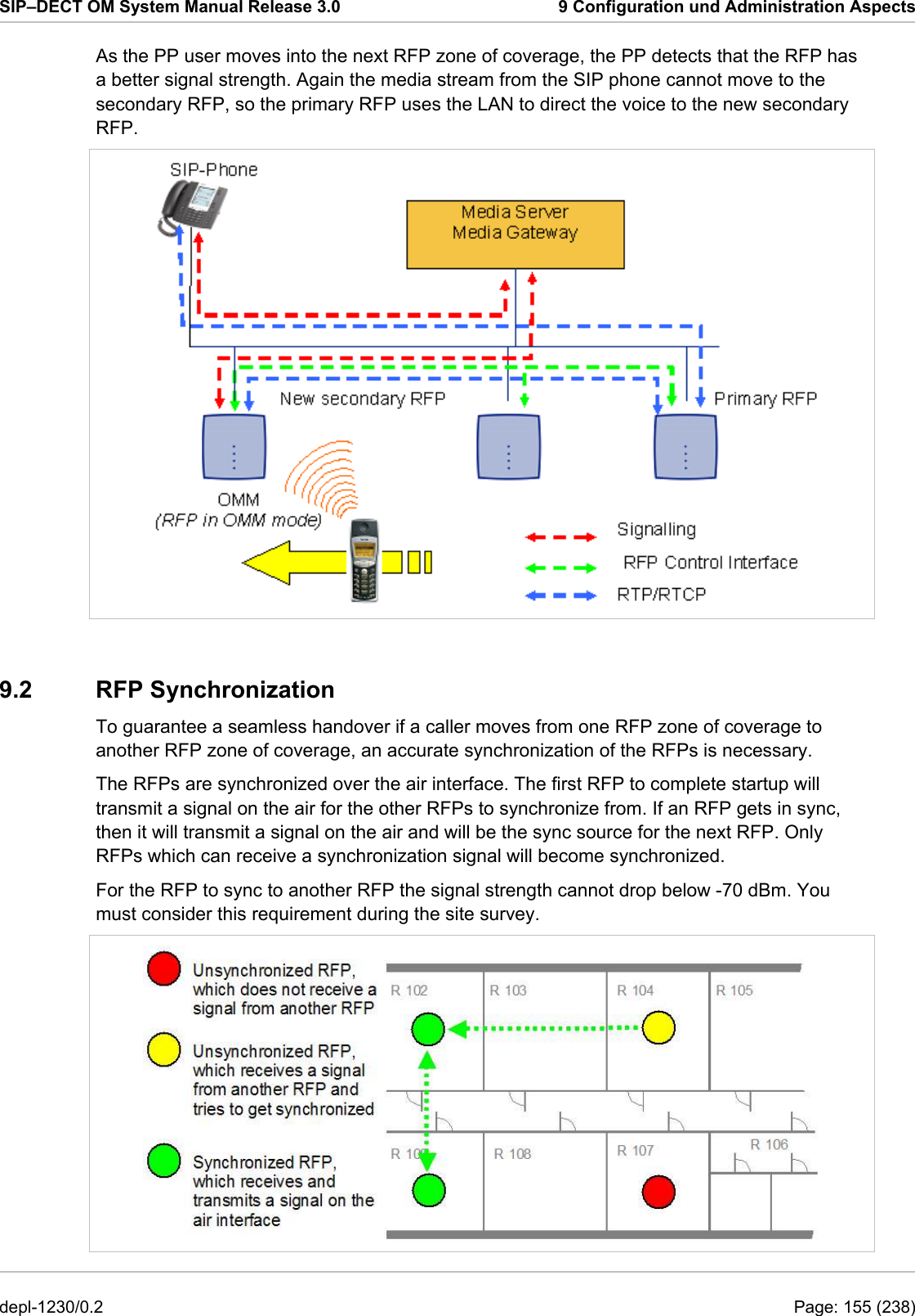
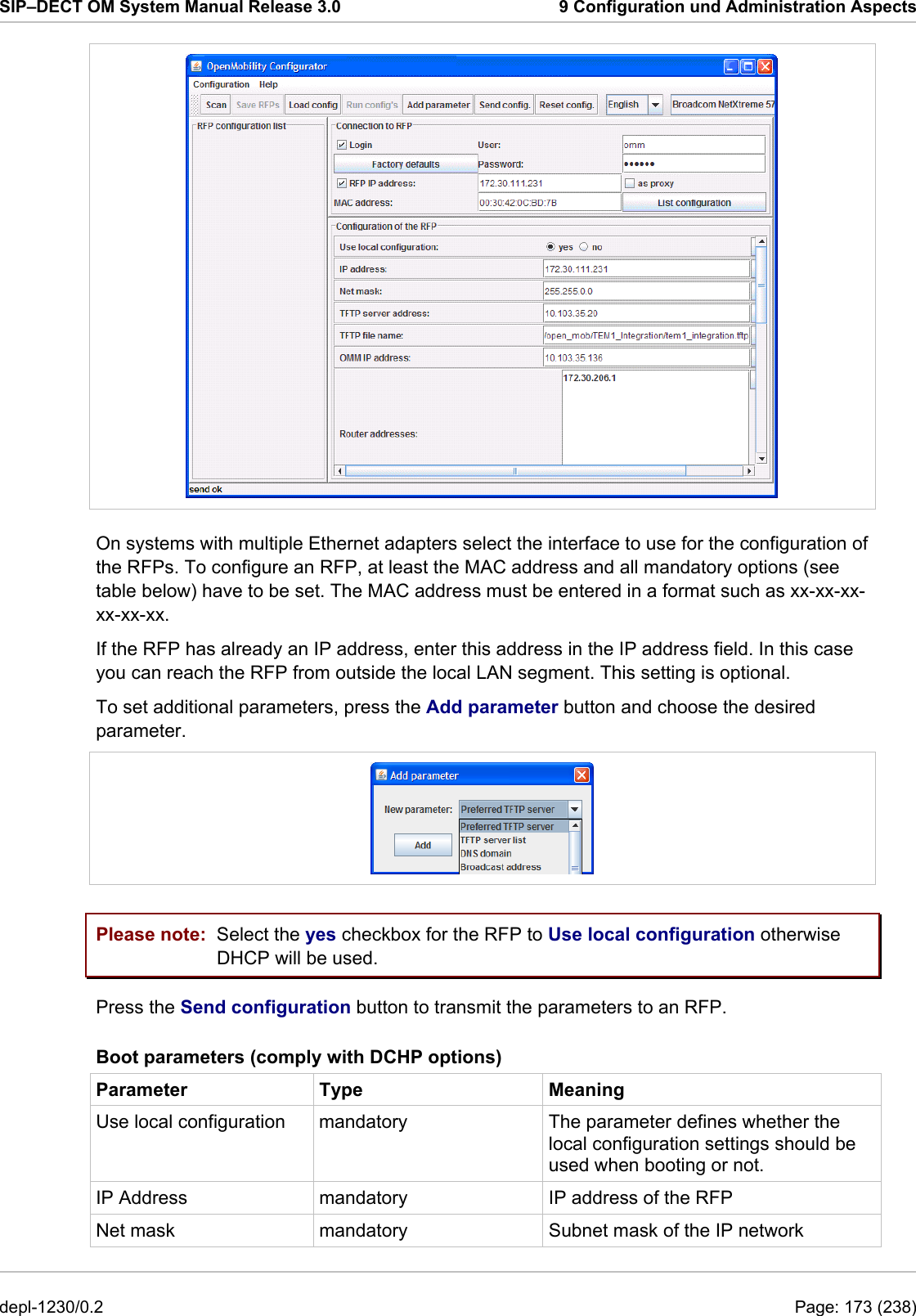
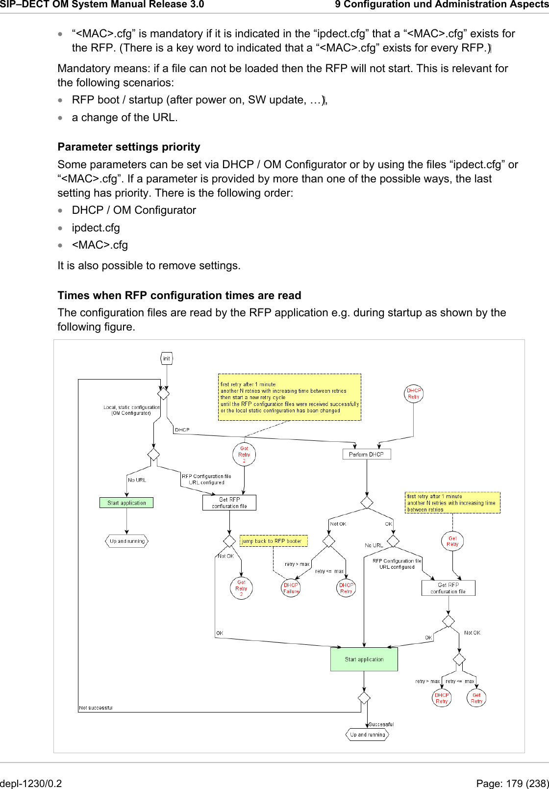
![SIP–DECT OM System Manual Release 3.0 9 Configuration und Administration Aspects 9.8 RFP Configuration Files RFP (L) 35/36/37 IP / RFP (L) 43 WLAN configuration files A new configuration parameter specifies the location of the software that will be installed into the flash of an RFP (L) 35/36/37 IP / RFP (L) 43 WLAN and activated by the OpenMobility Manager. OM_SwImageUrl=ftp://172.30.207.21/openmobility/SIP-DECT_3.0.dnld TFTP, FTP(S), HTTP(S) are supported for an RFP (L) 35/36/37 IP / RFP (L) 43 WLAN software update, please see section 9.11.5. RFP (L) 32/34 IP / RFP (L) 42 WLAN configuration files IP-RFPs support two RFP configuration files which are downloaded from a server to get configuration settings. There is one common file “ipdect.cfg” for all RFPs and there is one file specific file “<MAC>.cfg” for every single IP-RFP. The RFP requests the “ipdect.cfg” file if an URL is given. The RFP specific <MAC>.cfg is requested if this is indicated in the common “ipdect.cfg” file. It is possible that all RFPs request “ipdect.cfg” and only selected RFPs request the <MAC>.cfg to have a specific configuration on some RFPs. Standard IP settings Standard IP settings which are necessary to have access to the RFP configuration files are configured via DHCP (see chapter 9.5) or OM Configurator (see chapter 9.6). These are: IP address • • • • • • • • • • Net mask Gateway (i.e. router) Boot file name TFTP server Public option 224: “OpenMobility” (to identify the relevant DHCP offer) Domain Name Server (optional) Domain Name (optional) URL to the RFP configuration files All other parameters can be set by using an RFP configuration file even if standard DHCP options or OM Configurator parameters exist. Configuration file source A TFTP / FTP(S) / HTTP(S) URL specifies the protocol, server and path to access the RFP configuration files. The URL can include account data if appropriate. Syntax: {ftp|ftps|http|https}://[user:password@]server/[directory/] or tftp://server/[directory/] The URL configuration is done via DHCP option code 66 or the OM Configurator. “ipdect.cfg” is mandatory if an URL is given by DHCP option code 66 or local static configuration via the OM Configurator. depl-1230/0.2 Page: 178 (238)](https://usermanual.wiki/Mitel-Deutschland/68635RFP36U-01.UserManual-part2/User-Guide-1704945-Page-89.png)
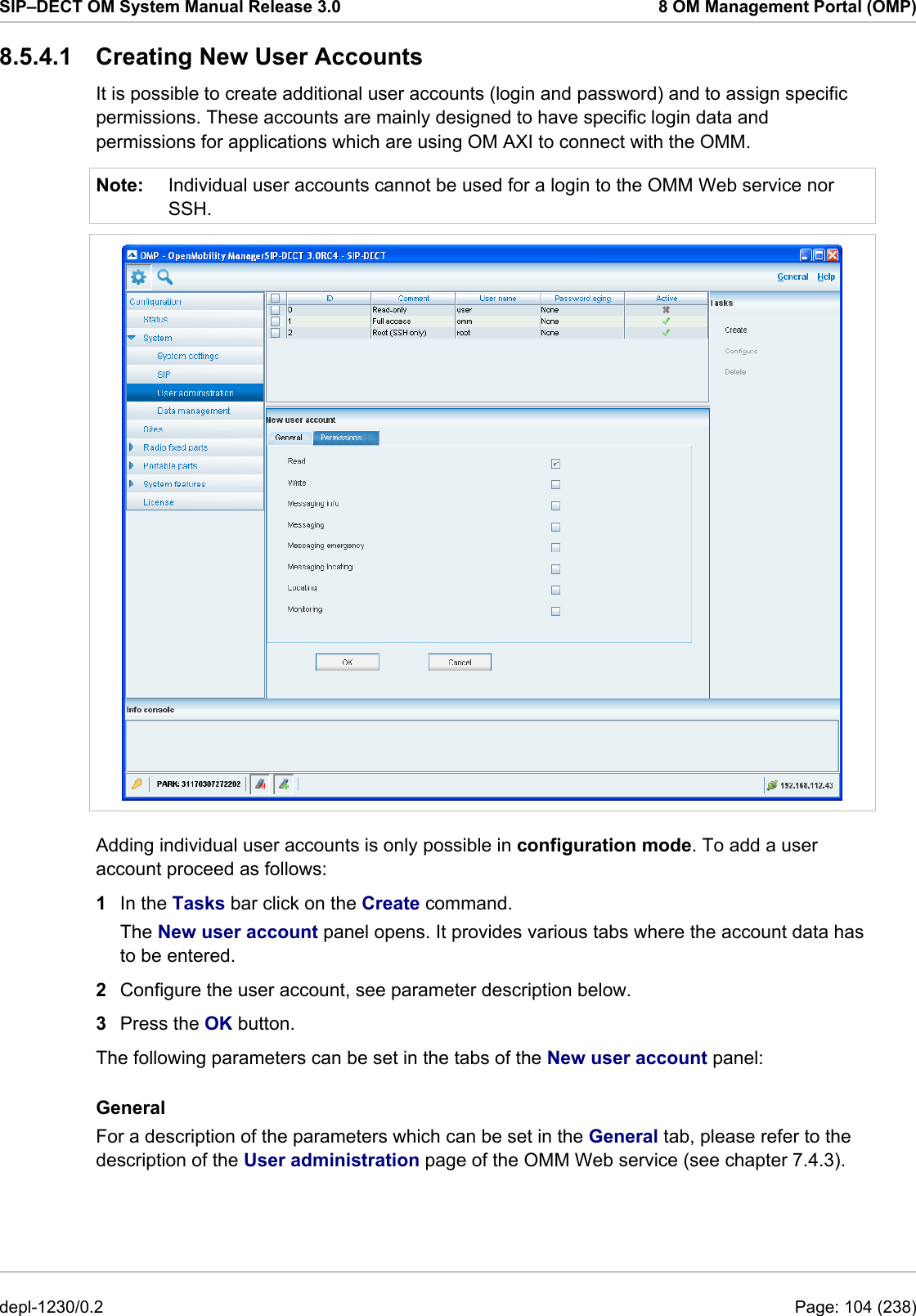
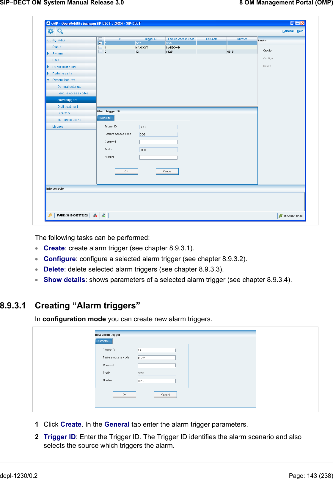
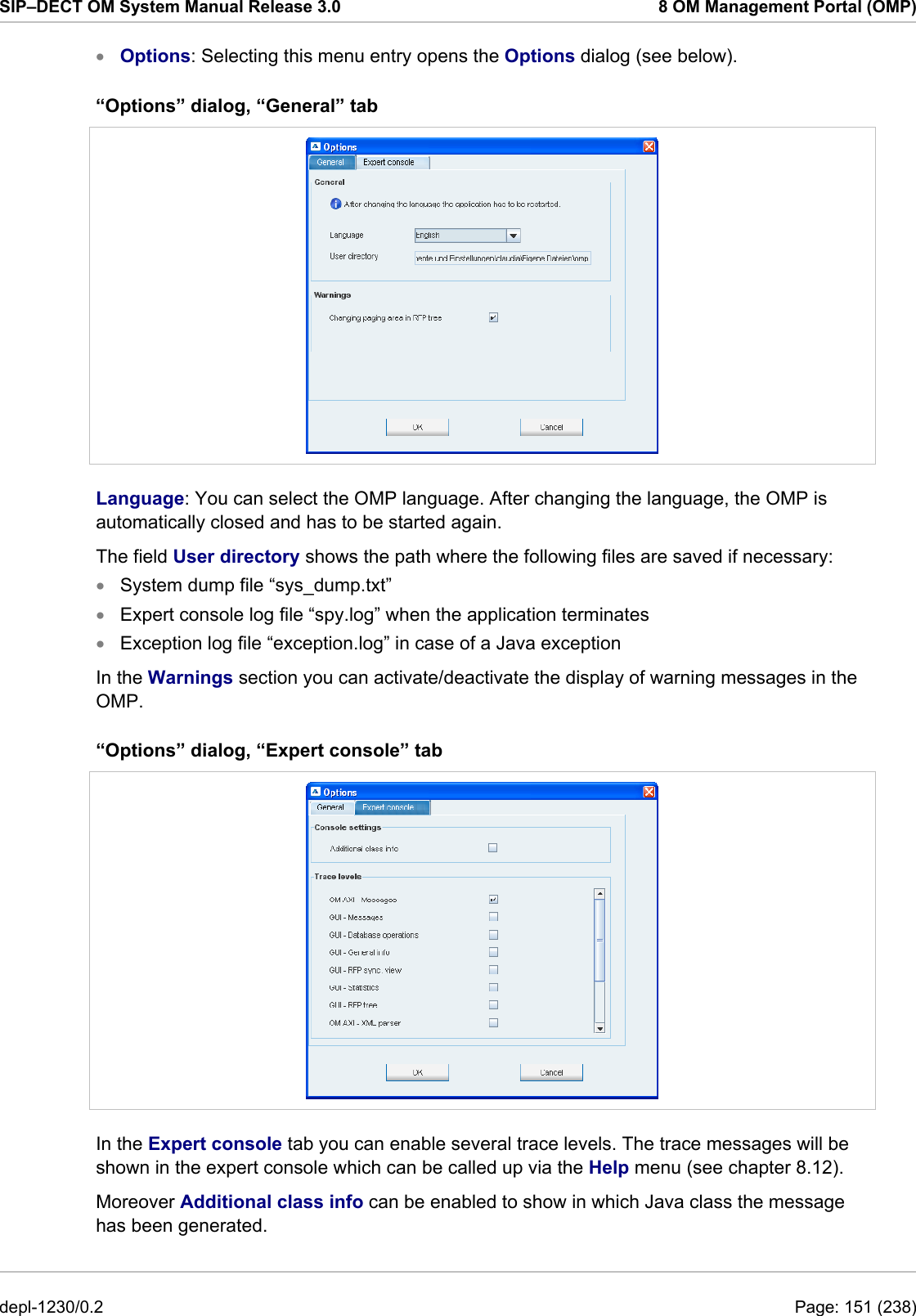
![SIP–DECT OM System Manual Release 3.0 9 Configuration und Administration Aspects 9.11.3 Configuring the Start Parameters The basic data for initializing OMM is stored in the file “/etc/sysconfig//SIP-DECT”. It can be edited to modify the OMM interface. ############################################## # OMM configuration file ############################################## # if you use a different interface for omm activate/correct parameter below #OMM_IF="eth0" # OMM_CONFIG_FILE=/opt/SIP-DECT/tmp/omm_conf.txt # #if you use OMM resiliency for OMM activate parameter below with OMMs IP adresses #OMM_RESILIENCY="192.168.0.1:192.168.0.2" # # Automatic OMM database import: # TFTP / FTP / HTTP(S) URL specifies the import server and file #RST_URL=ftp://download-url.com/directory/file.dat # country tones: # VS_COUNTRY_DEU = 1, VS_COUNTRY_GBR = 2, VS_COUNTRY_CHE = 3, VS_COUNTRY_ESP = 4, VS_COUNTRY_FRA = 5, VS_COUNTRY_ITA = 6, # VS_COUNTRY_RUS = 7, VS_COUNTRY_BEL = 8, VS_COUNTRY_NLD = 9, VS_COUNTRY_CZE = 10, VS_COUNTRY_AUT = 11, VS_COUNTRY_DNK = 12, # VS_COUNTRY_SVK = 13, VS_COUNTRY_FIN = 14, VS_COUNTRY_HUN = 15, VS_COUNTRY_POL = 16, VS_COUNTRY_BLR = 17, VS_COUNTRY_EST = 18, # VS_COUNTRY_LVA = 19, VS_COUNTRY_LTU = 20, VS_COUNTRY_UKR = 21, VS_COUNTRY_NOR = 22, VS_COUNTRY_EUN = 23, VS_COUNTRY_SWE = 24, # VS_COUNTRY_TWN = 25 COUNTRY="2" Parameters Description OMM_IF Interface for communicating with the RFPs (by default: eth0) OMM_CONFIG_FILE Directory containing the OMM configuration file (by default: /etc/omm_conf.txt) OMM_RESILIENCY In case of OMM redundancy, enter the two IP addresses of the OMMs. See also section 9.13. Restore URL Restore URL for an automatic OMM database import (see chapter 7.4.6.2) Country tone schema 9.11.4 Specific Commands – Troubleshooting /etc/init.d/sip-dect [start|stop|restart]. The command line interface for OMM is accessible via telnet on port 8107. Malfunction COUNTRY The OMM software has been installed but does not work automatically when the PC starts. The command below stops or starts OMM manually (User root): To check whether OMM is working, see the list of procedures for the “SIP-DECT” process. If OMM does not start, delete the lock file “/var/lock/subsys/SIP-DECT”. depl-1230/0.2 Page: 186 (238)](https://usermanual.wiki/Mitel-Deutschland/68635RFP36U-01.UserManual-part2/User-Guide-1704945-Page-97.png)
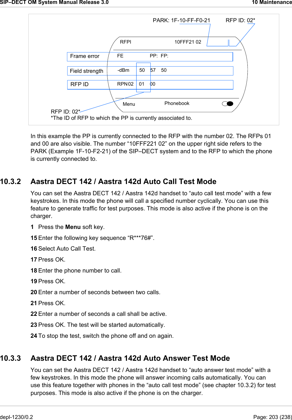
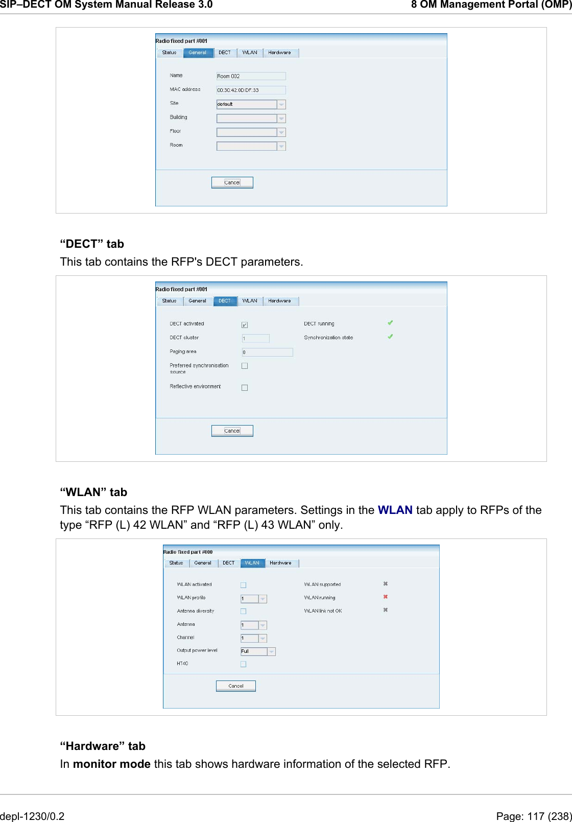
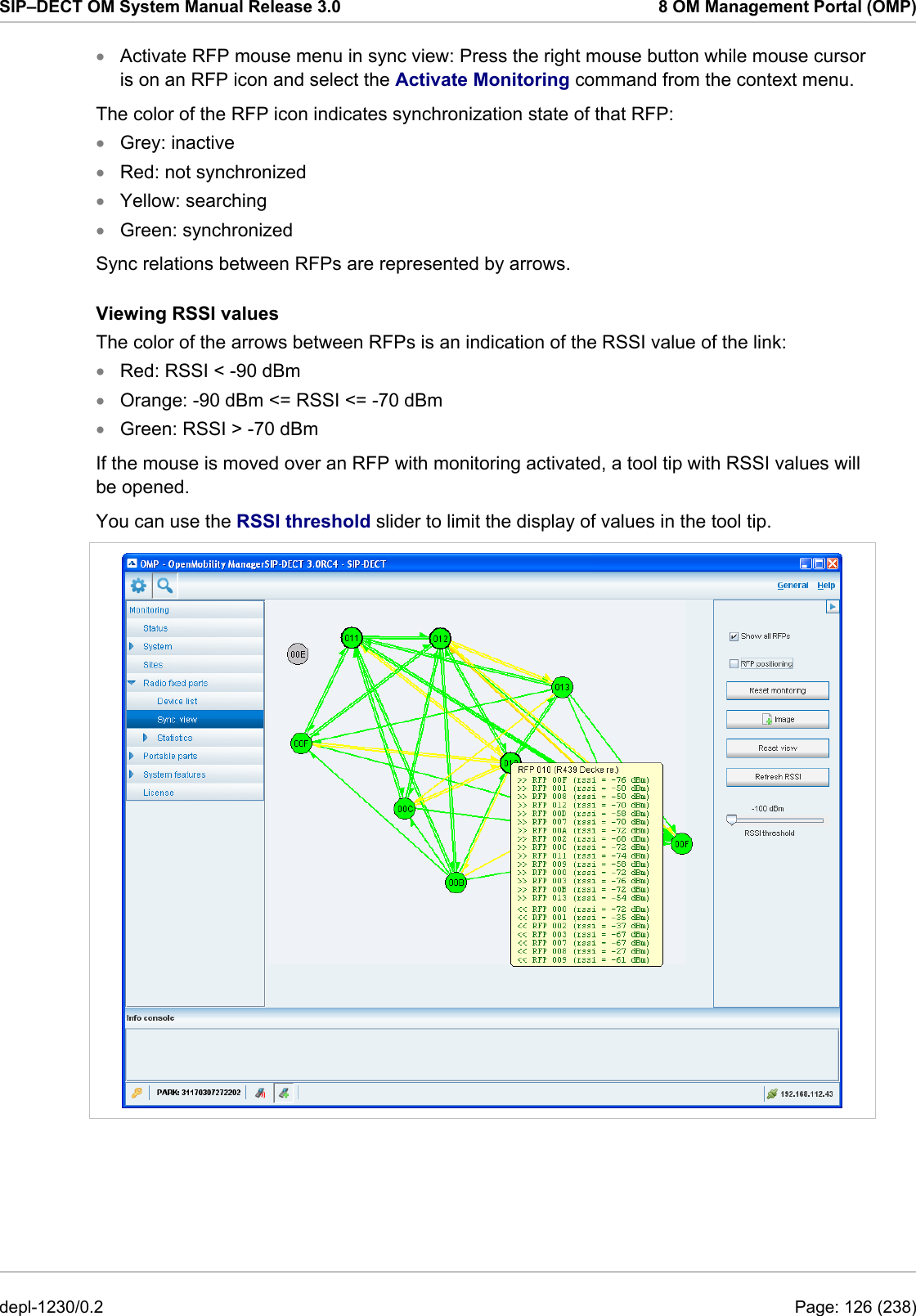
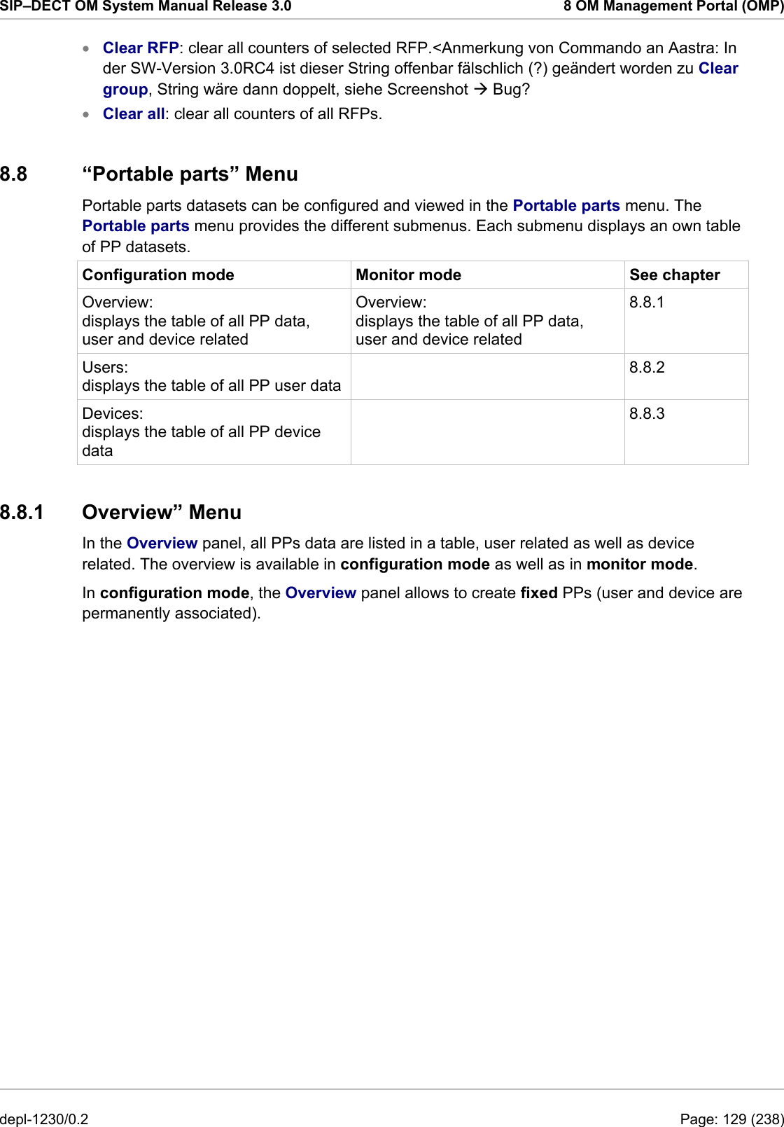
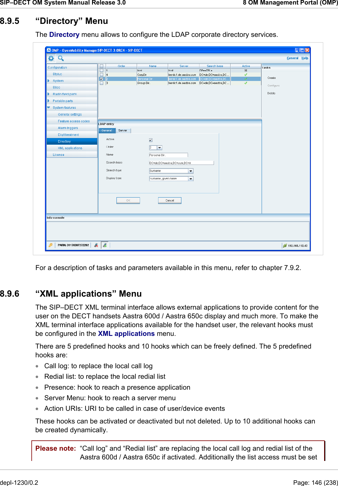
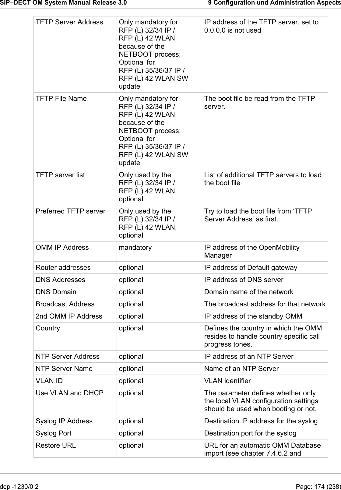
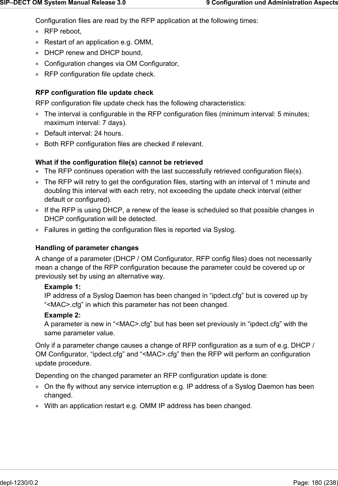
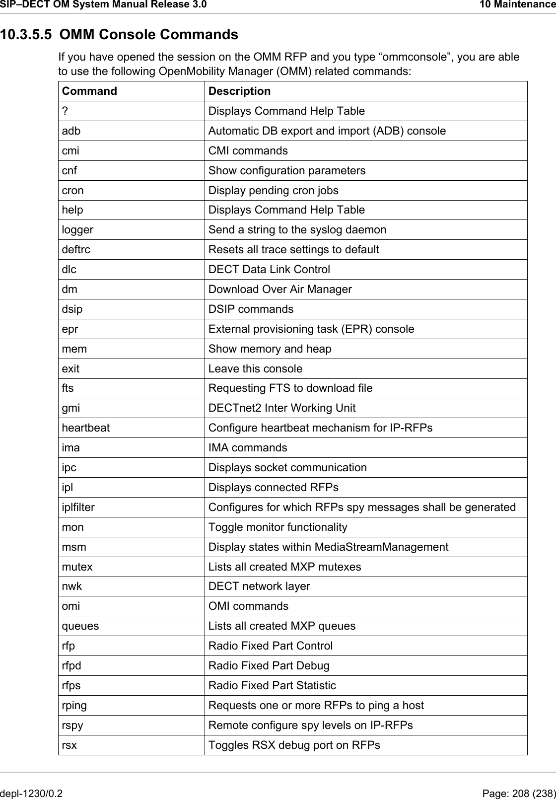
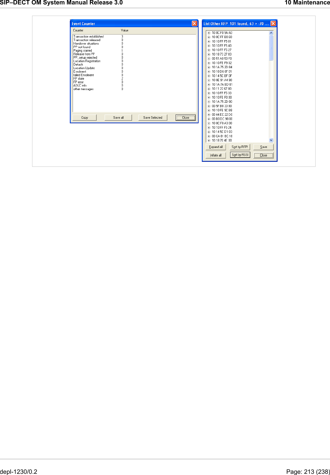
![SIP–DECT OM System Manual Release 3.0 10 Maintenance 10.3.5.4 RFP Console Commands If you type ip_rfpconsole you are able to use the following commands on each RFP: Command Description ? Displays Command Help Table help Displays Command Help Table logger Send a string to the syslog daemon deftrc Resets all trace settings to default dsp Shows channel config dump Creates system state dump file /tmp/sys_dump.txt.gz mem Show memory and heap exit Leave this console heap Shows heap buffer statistics lec Adjust linear echo canceler parameters media Display state of media channels mutex Lists all created MXP mutexes omms Shows connection status to OMM(s) queues Lists all created MXP queues reset Resets the IPRFP application resume Resume bmc activity rsx Allows RSX connection to BMC via TCP Lists all created MXP semaphores spy suspend Suspend bmc activity tasks Lists all running MXP tasks Displays the state of voice handling wlan runtime Report the process runtime sem Set/display spy levels: [ <key #> <level #> ] voice Configure wlan card on cmdline lu10 Lu10 SDU <-> PDU converter (RFP (L) 35/36/37 IP and RFP (L) 43 WLAN only) mroute Display media routes Please note: The “spy” command enables you to increase the level of syslog messages. This should be only used by instructions of the support organization because it can harm the system operation. depl-1230/0.2 Page: 207 (238)](https://usermanual.wiki/Mitel-Deutschland/68635RFP36U-01.UserManual-part2/User-Guide-1704945-Page-118.png)
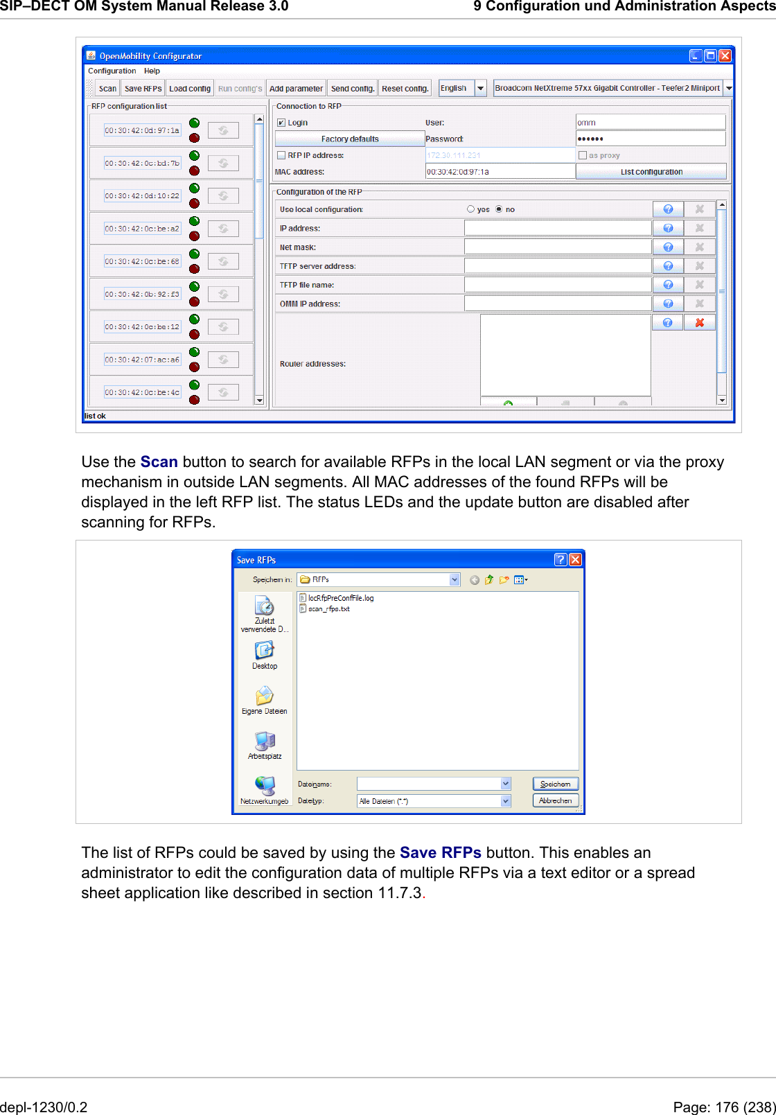
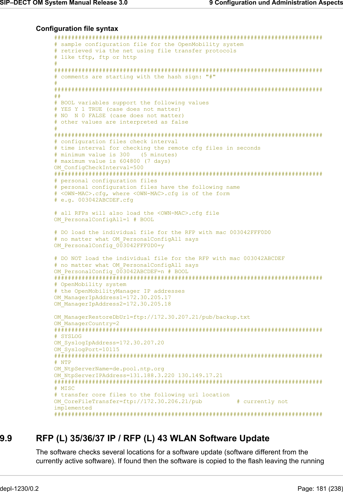
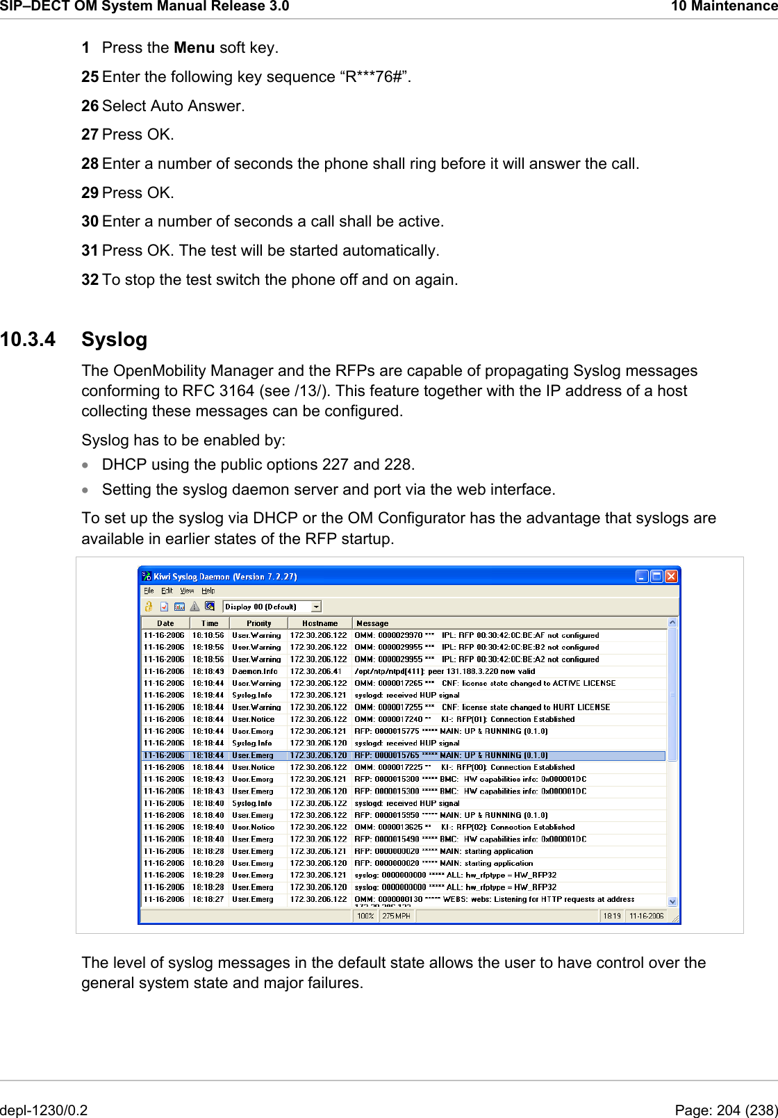
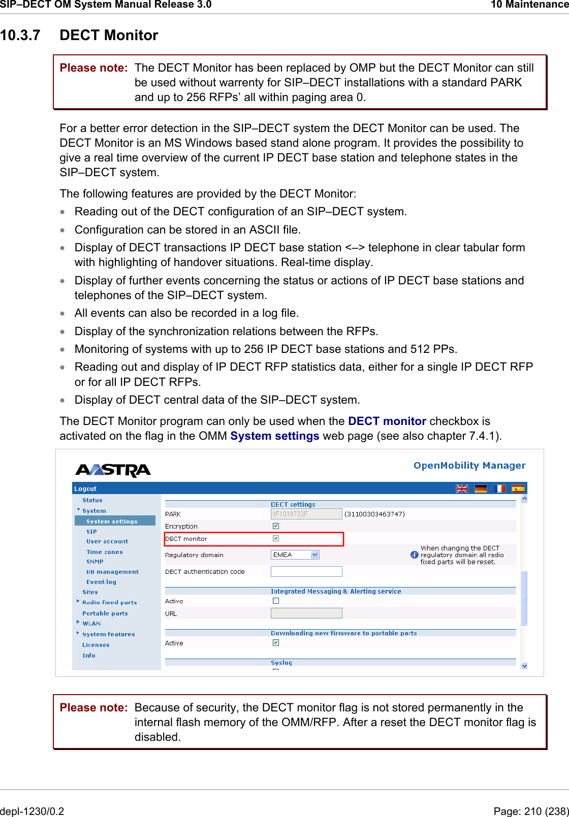
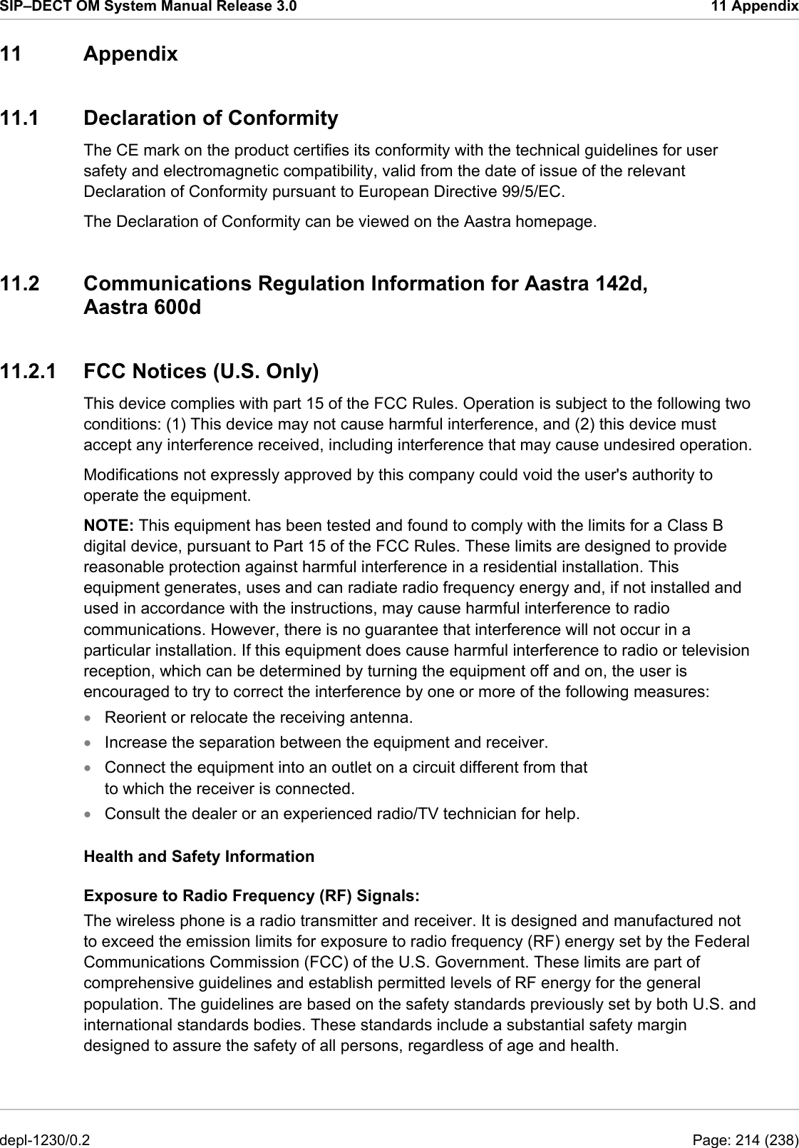
![SIP–DECT OM System Manual Release 3.0 10 Maintenance rtt Set event flag for high RTT values / clears values sem Lists all created MXP semaphores spy Set/display spy levels: [ <key #> <level #> ] standby Displays redundant OMMs stat Statistic sync Commands for RFP synchronisation tasks Lists all running MXP tasks tzone Time zone commands uptime Displays system uptime ver Version information wlan Display states within Wireless LAN Management axi AXI commands runtime Report the process runtime upd Displays update status of RFPs xml XML browser task (XML) console Please note: Please note: The “spy” command enables you to increase the level of syslog messages especially for subsystems of the OMM. This should be only used by instructions of the support organization because it can harm the system operation. 10.3.6 Core File Capturing If there some fatal error on the OMM and the software is breaking down, the OMM is able to generate memory dump. If you send these generated core files to the support, you help them to resolve this failures. The OMM is able to store these core files on a TFTP server in your local network. To enabling core file creation write on the OMM command line: ldb core=yes ldb core_srv=server-ip – TFTP server IP address ldb core_path=path – file path on TFTP server (must be writeable) If no ldb_core_srv and ldb_core_path is given, the OMM tries to write the core files to the TFTP server and path where the OMM/RFP application was downloaded. After restarting the OMM, the core files are automatically transferred to the TFTP server. The TFTP server must allow writing new files, this is usually not standard. To disable core file capturing writer on command line: ldb core=. depl-1230/0.2 Page: 209 (238)](https://usermanual.wiki/Mitel-Deutschland/68635RFP36U-01.UserManual-part2/User-Guide-1704945-Page-120.png)
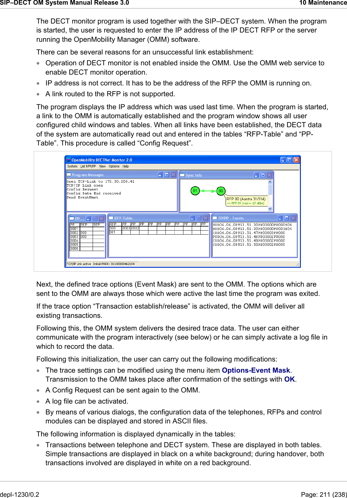
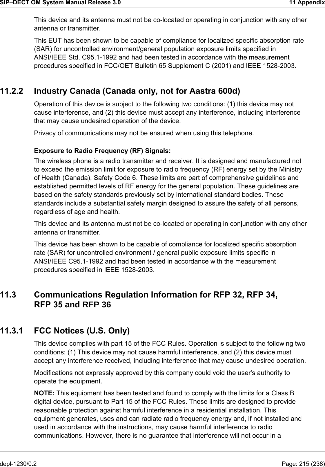
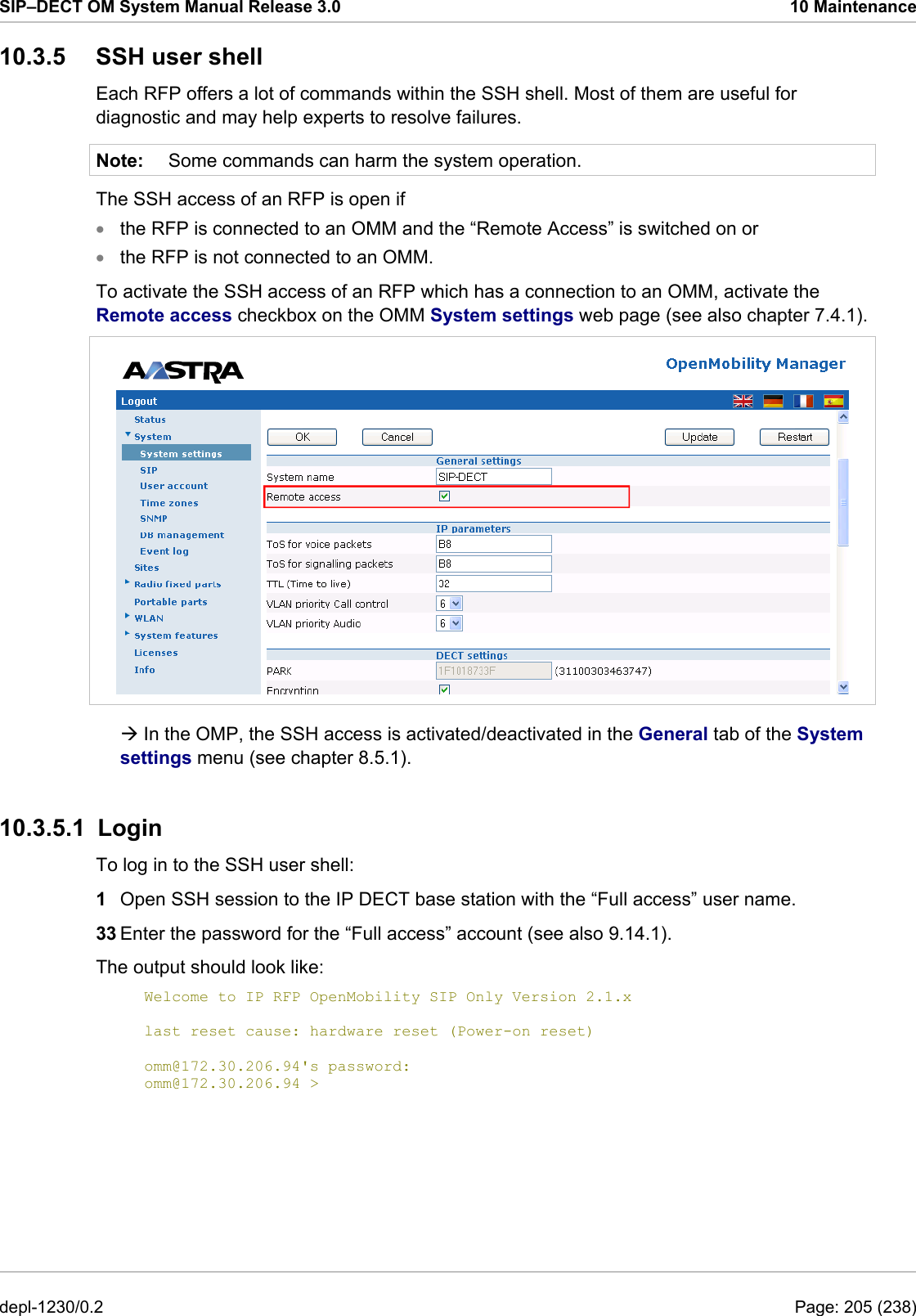
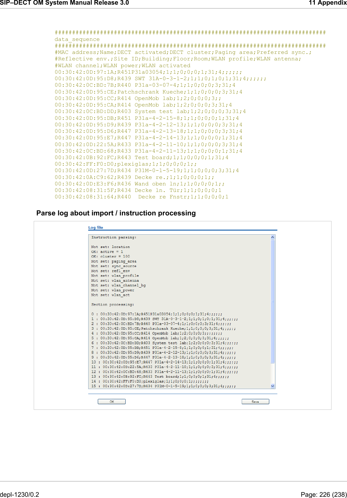
![SIP–DECT OM System Manual Release 3.0 11 Appendix start_number = 5401 no_of_number = 10 ac = 1001 additional_pin = number sip_user = number sip_pw = number sos_number=5002 mandown_number=5002 # ---------------------# # data sequence: # ---------------------# # 1. number # 2. name # 3. AC # 4. IPEI # 5. additionalId # 6. SIP user # 7. SIP password # 8. sos no # 9. mandown no # 10. locatable (ignored by Web import and always set to inactive) # 11. localization (ignored by Web import and always set to inactive) # 12. tracking (ignored by Web import and always set to inactive) # 13. descr1 (ignored by Web import and always set to "") # 14. descr2 (ignored by Web import and always set to "") data_sequence;;;;;;;;;;;;; # 1. number;2. name;3. AC;4. IPEI ;5. additionalId;6. SIP user;7. SIP password;8. sos no;9. mandown no;10. locatable;11. localization;12. tracking;13. descr1;14. descr2 101;PP 1;;0081008625768;;;;;;;;;; 104;PP 4;;0007701154842;;;;;;;;;; ;Kiel Phone1;;0127105395099;5401;5401;5401;30;30;;;;; ;Karl May;;;;;;;;;;;; ;Karl Valentin;;;;;;;;;;;; ;Karl Heinz;;;;;;;;;;;; ;Radi Radenkowicz;;;;;;;;;;;; ;Radi Rettich;;;;;;;;;;;; ;Wadi Wade;;;;;;;;;;;; Parse log about import / instruction processing OK: start_number = 5401 OK: ac = 1001 OK: additional_pin = number OK: sip_user = number OK: sip_pw = number OK: sos_number = 5002 OK: mandown_number = 5002 OK: no_of_number = 10 Section processing: […] 11.7.2 RFP Configuration File / Central (OMM Database) Import of RFP configurations using files is possible with Web Service or OMM Management portal. depl-1230/0.2 Page: 223 (238)](https://usermanual.wiki/Mitel-Deutschland/68635RFP36U-01.UserManual-part2/User-Guide-1704945-Page-134.png)
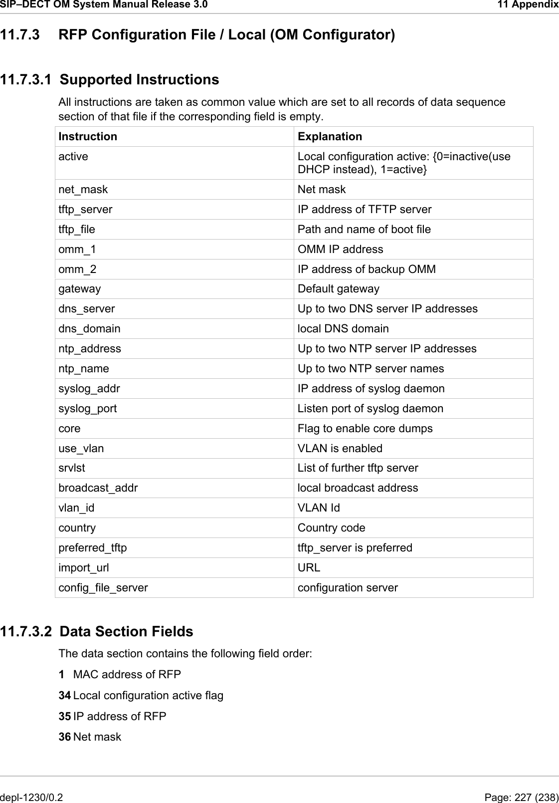
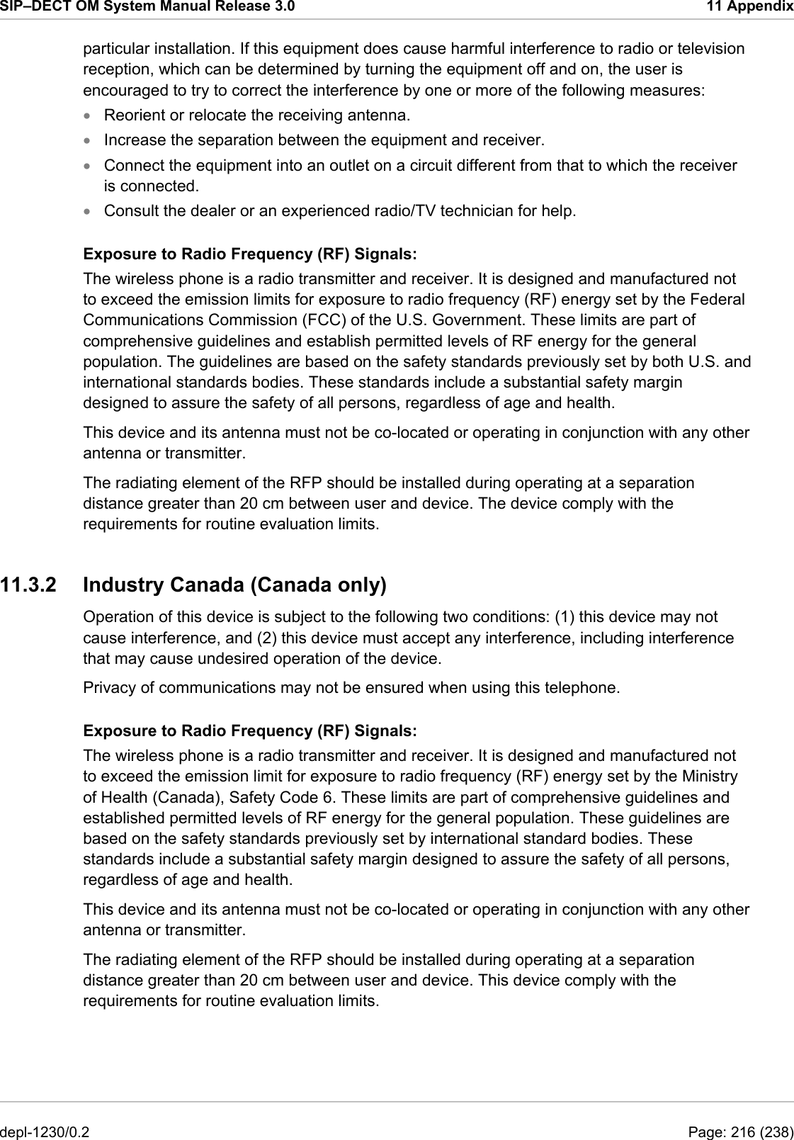
![SIP–DECT OM System Manual Release 3.0 11 Appendix import_url = https://server/importfiles/ommxy_conf.gz # 2. ACTIVE_FLAG #18. SRVLIST config_file_server = https://server/configfiles/ # --------------# # data sequence # # --------------# # 1. MAC_ADDR ! no instruction supported ! # 3. RFPADDR ! no instruction supported ! # 4. NET_MASK # 5. TFTP_SERVER # 6. TFTP_FILE # 7. OMM1 # 8. OMM2 # 9. GATEWAY #10. DNS_SERVER #11. DNS_DOMAIN #12. NTP_ADDR #13. NTP_NAME #14. SYSLOG_ADDR #15. SYSLOG_PORT #16. CORE #17. USE_VLAN #19. BROADCAST_ADDR #20. VLAN_ID #21. COUNTRY #22. PREFERRED_TFTP #23. IMPORT_URL #24. CONFIG_FILE_SERVER data_sequence 00-30-42-01-01-01;;172.30.111.1 00-30-42-02-02-02;;172.30.111.2 Parse log about import / instruction processing ok: active = 1 ok: net_mask = 255.255.0.0 ok: tftp_server = 172.30.200.92 ok: tftp_file = iprfp2g.tftp ok: omm_1 = 172.30.111.188 ok: omm_2 = 172.30.11.181 ok: gateway = 172.30.0.2 ok: dns_server = 172.30.0.4,172.30.0.21 ok: dns_domain = Aastra.com ok: ntp_addr = 192.53.103.108,192.53.103.104 ok: ntp_name = ptbtime1.ptb.de,ptbtime2.ptb.de ok: syslog_addr = 172.30.200.92 not set: syslog_port ok: core = 0 ok: use_vlan = 1 ok: srvlist = 172.30.0.4,172.30.0.21 ok: broadcast_addr = 172.30.255.255 ok: vlan_id = 4 ok: country = 1 ok: preferred_tftp = 1 ok: import_url = https://server/importfiles/ommxyz_conf.gz ok: config_file_server = https://server/configfiles/ :parsing ok: processing of section: data_sequence […] create data: depl-1230/0.2 Page: 229 (238)](https://usermanual.wiki/Mitel-Deutschland/68635RFP36U-01.UserManual-part2/User-Guide-1704945-Page-140.png)
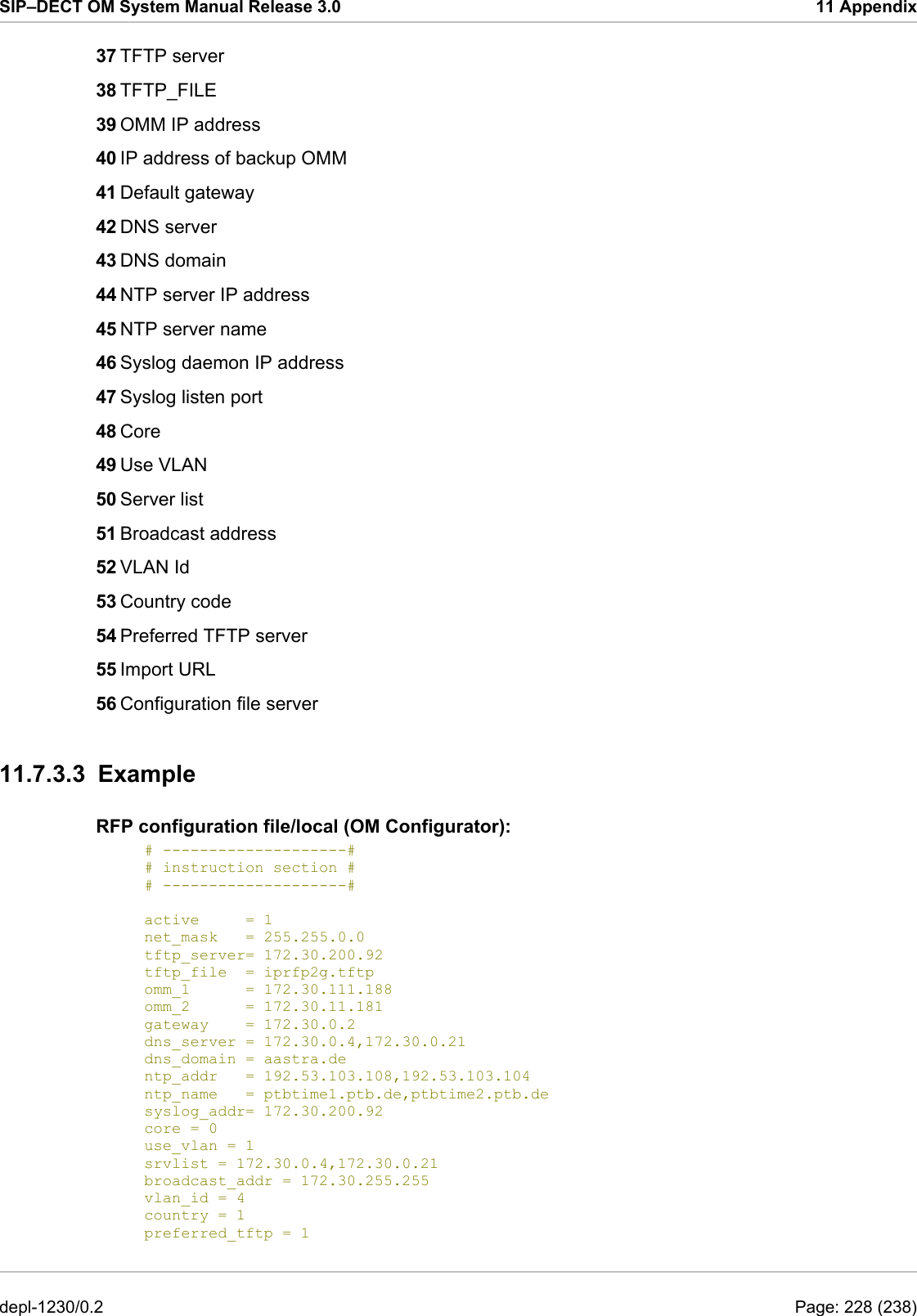
![SIP–DECT OM System Manual Release 3.0 11 Appendix […] RFP configuration: […] 11.8 RFP Export File Format General RFP export files are created by OMM Management Portal in ‘csv’-file format which can be easily viewed by a spreadsheet application. Export file contains all or a part of the following parameters: MAC address • • • • • • • • • • • • • • • • Location name DECT active Cluster Paging area Synchronisation source Reflective environment Site Building Floor Room WLAN profile reference WLAN antenna WLAN Channel_bg WLAN power WLAN active Example Following example RFP export file contains all exportable RFP parameters and is re-importable by OMM Management Portal. ################################################## # RFP data export file: '/home/user/example.csv' # Date: 24.09.10 Time: 15:58:19 ################################################## # # Exported parameters: # # MAC address # Name # DECT activated # DECT cluster # Paging area # Preferred sync. # Reflective env. # Site ID # Building # Floor # Room # WLAN profile # WLAN antenna depl-1230/0.2 Page: 230 (238)](https://usermanual.wiki/Mitel-Deutschland/68635RFP36U-01.UserManual-part2/User-Guide-1704945-Page-141.png)
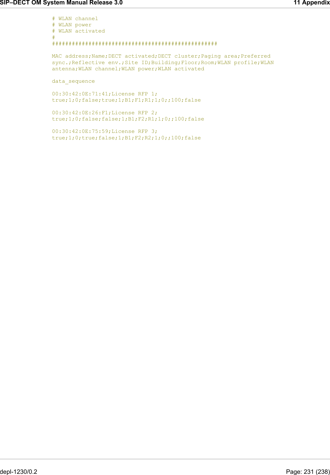
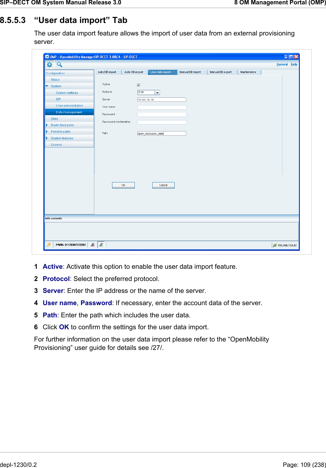
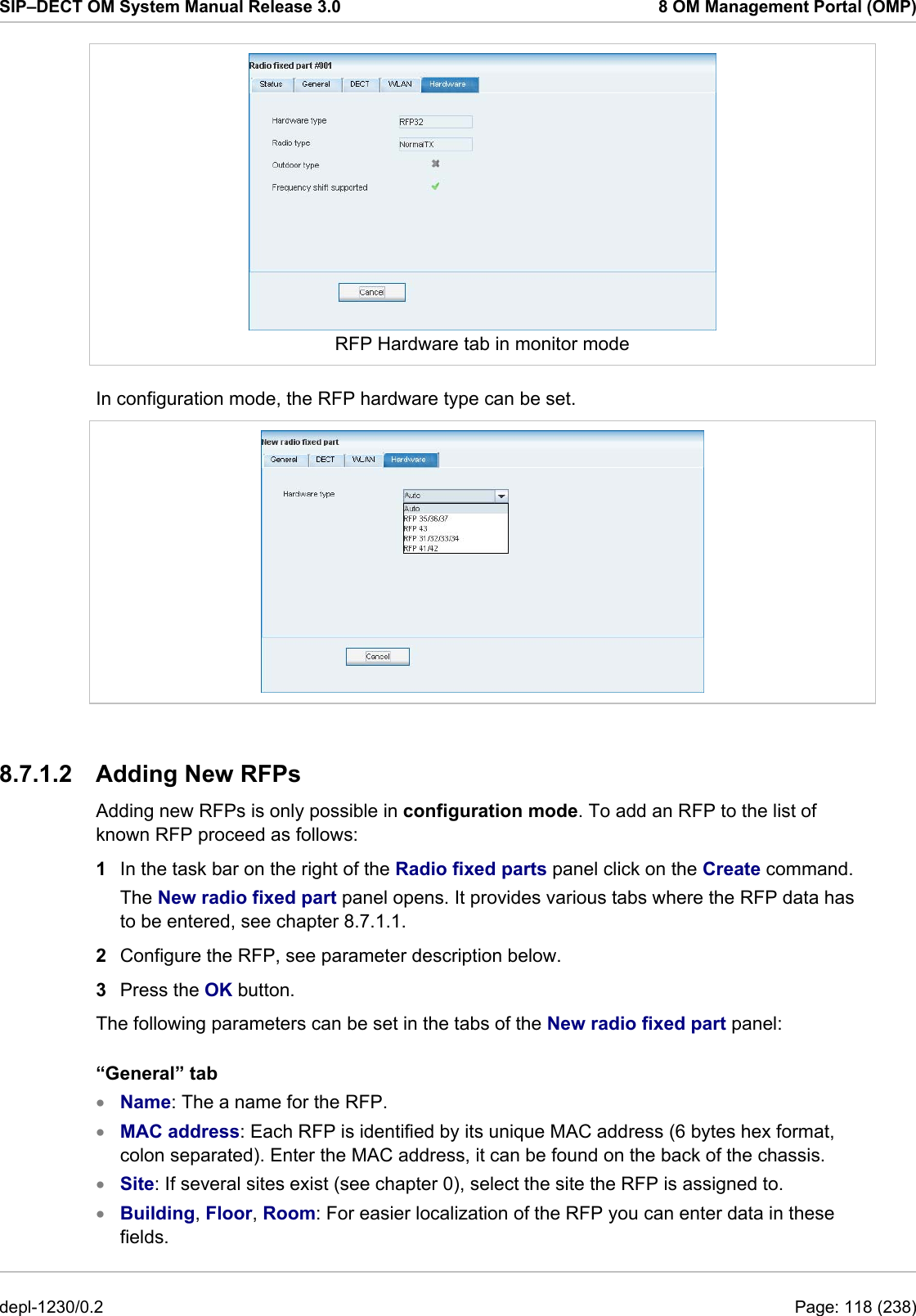
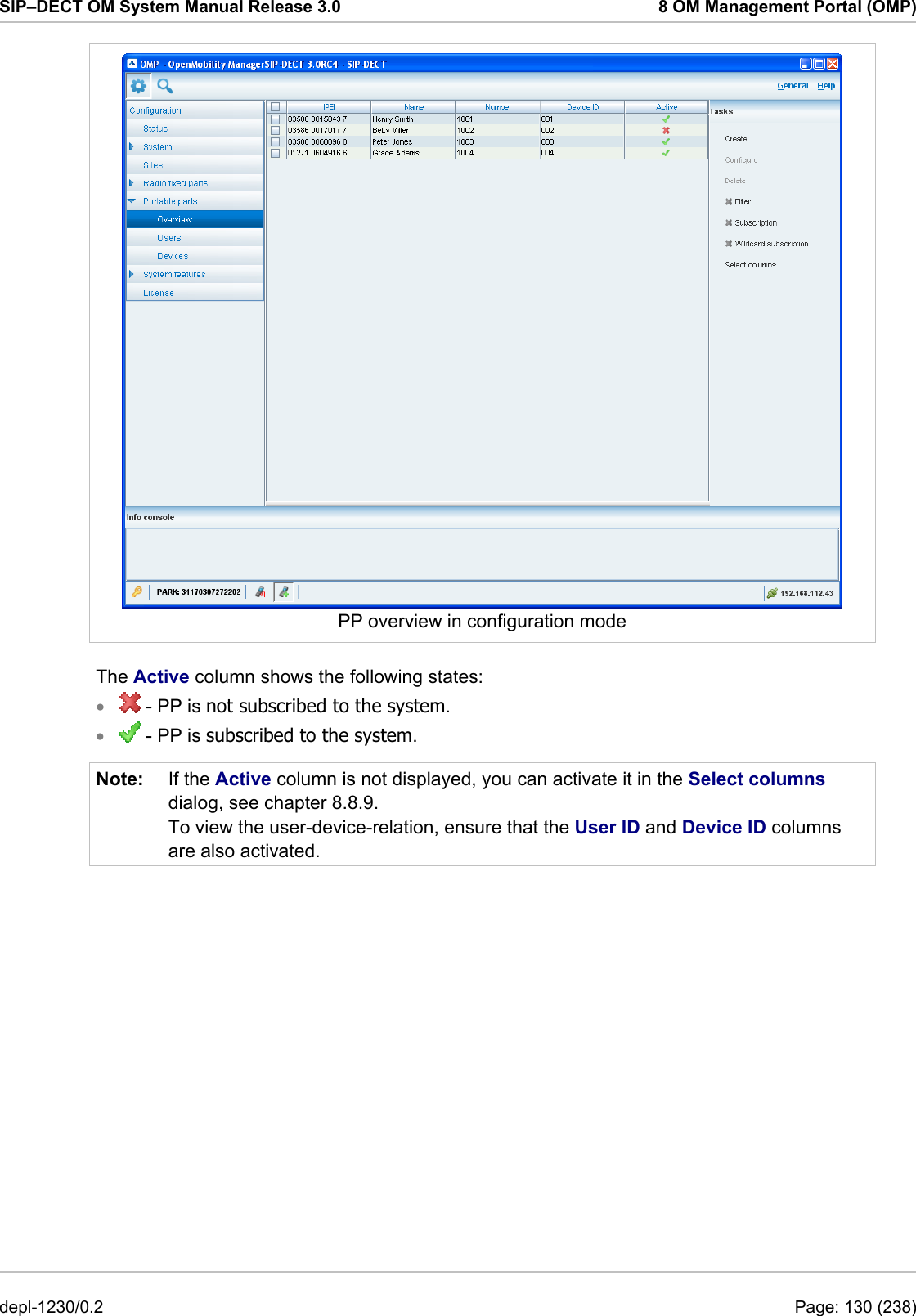
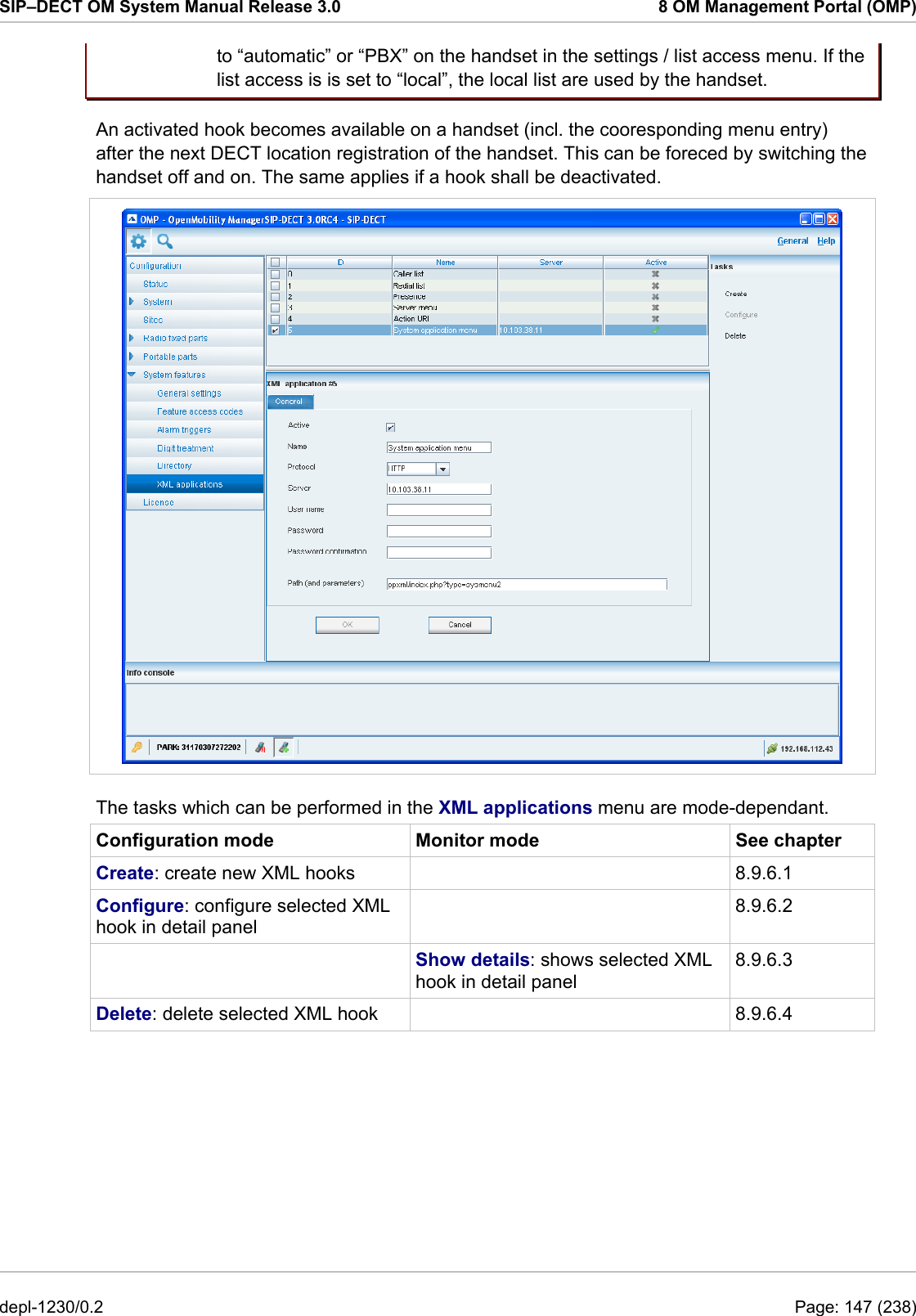
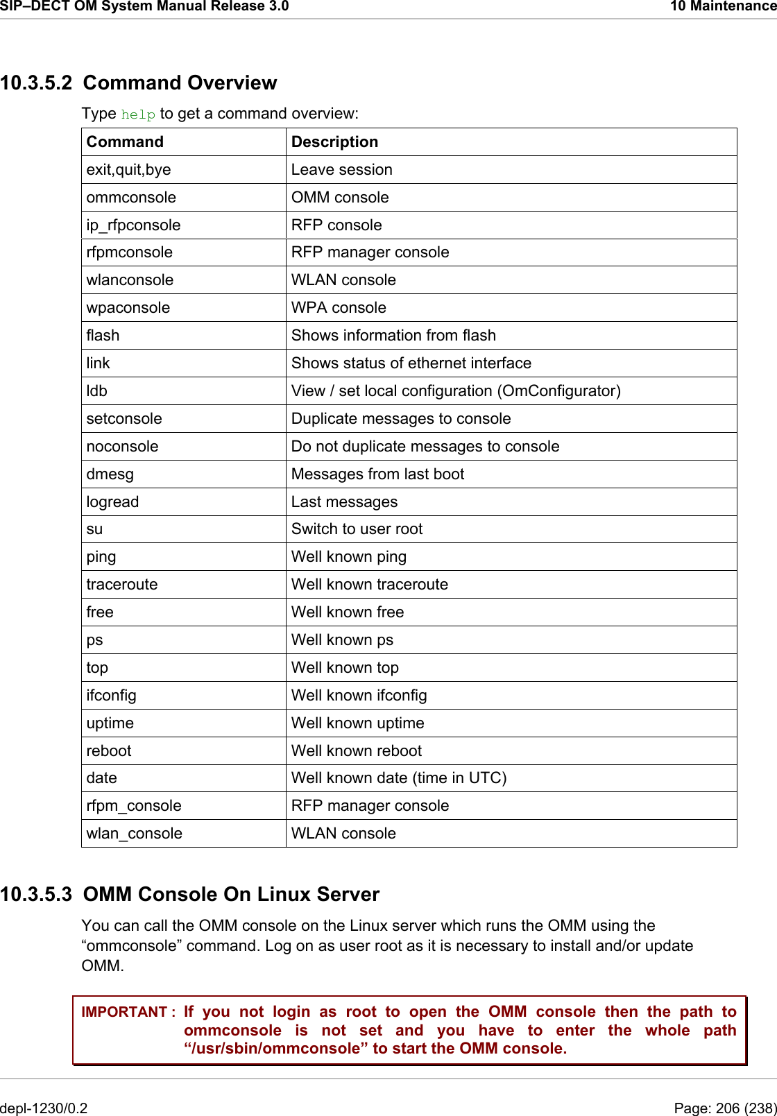
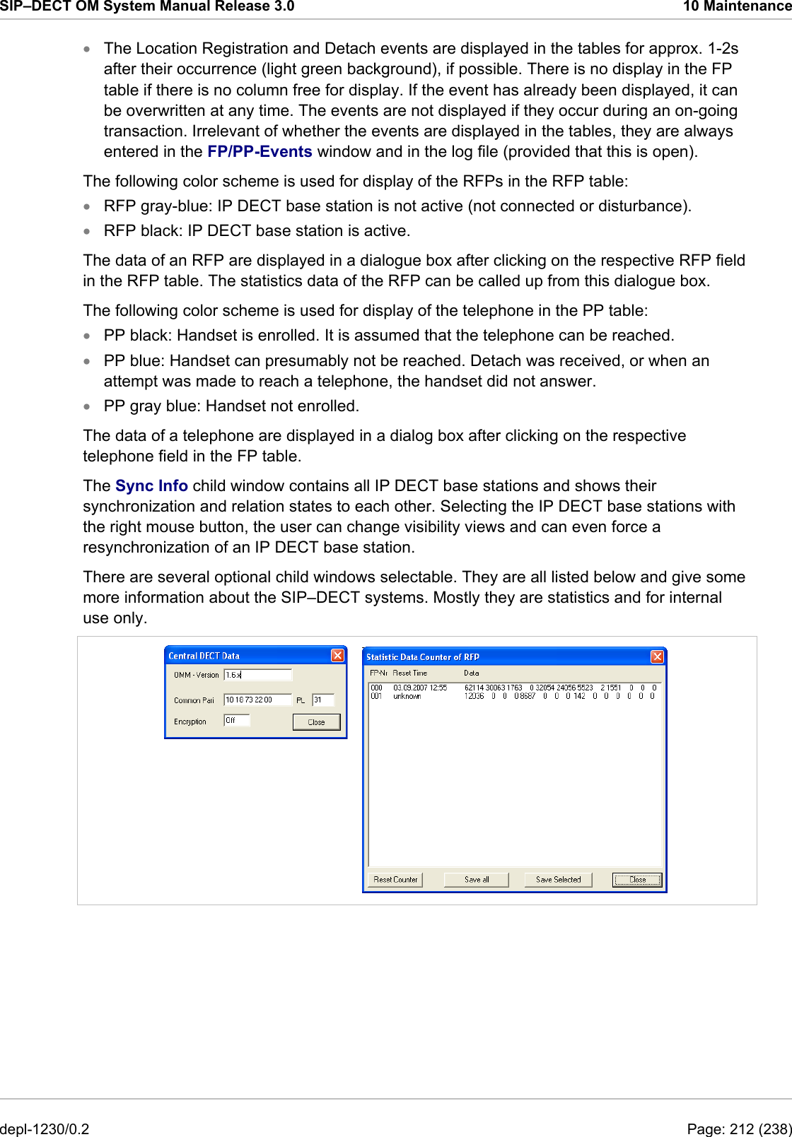
![SIP–DECT OM System Manual Release 3.0 11 Appendix IP-RFP Protocol Server port Client port HTTP/HTTPS client for the SIP–DECT XML terminal interface tcp 80/443 > 1024 RFP control protocol tcp client 16321 >=1024 (see note) HTTP server (redirect to OMM web server (http)) tcp server 80 or as configured any SSH server tcp server 22 any DHCP client udp 67 68 TFTP client udp 69 / given by server >=1024 (see note) OMCFG server udp 64000 64000 NTP client udp 123 123 Syslog client udp 514 or as configured 514 DNS client udp 53 >=1024 (see note) SNMP agent (server) udp 161 any SNMP trap agent (client) udp >=1024 (see note) 162 RSXport (debug only) tcp server 38477 any RTP/RTCP (server) udp Range of [RTP port base + 71] even ports for RTP, odd ports for RTCP. Port base is 16320 or as configured. any RTP/RTCP (client) udp any Range of [RTP port base + 71] even ports for RTP, odd ports for RTCP. Port base is 16320 or as configured. Note: Unbound ports start at port 1024. depl-1230/0.2 Page: 233 (238)](https://usermanual.wiki/Mitel-Deutschland/68635RFP36U-01.UserManual-part2/User-Guide-1704945-Page-144.png)