Mitsumi Electric WML-C07 Bluetooth module WML-C07## User Manual functional description
Mitsumi Electric Co., Ltd. Bluetooth module WML-C07## functional description
UserManual.wiki
>
Mitsumi Electric
>
WML C07 User Manual
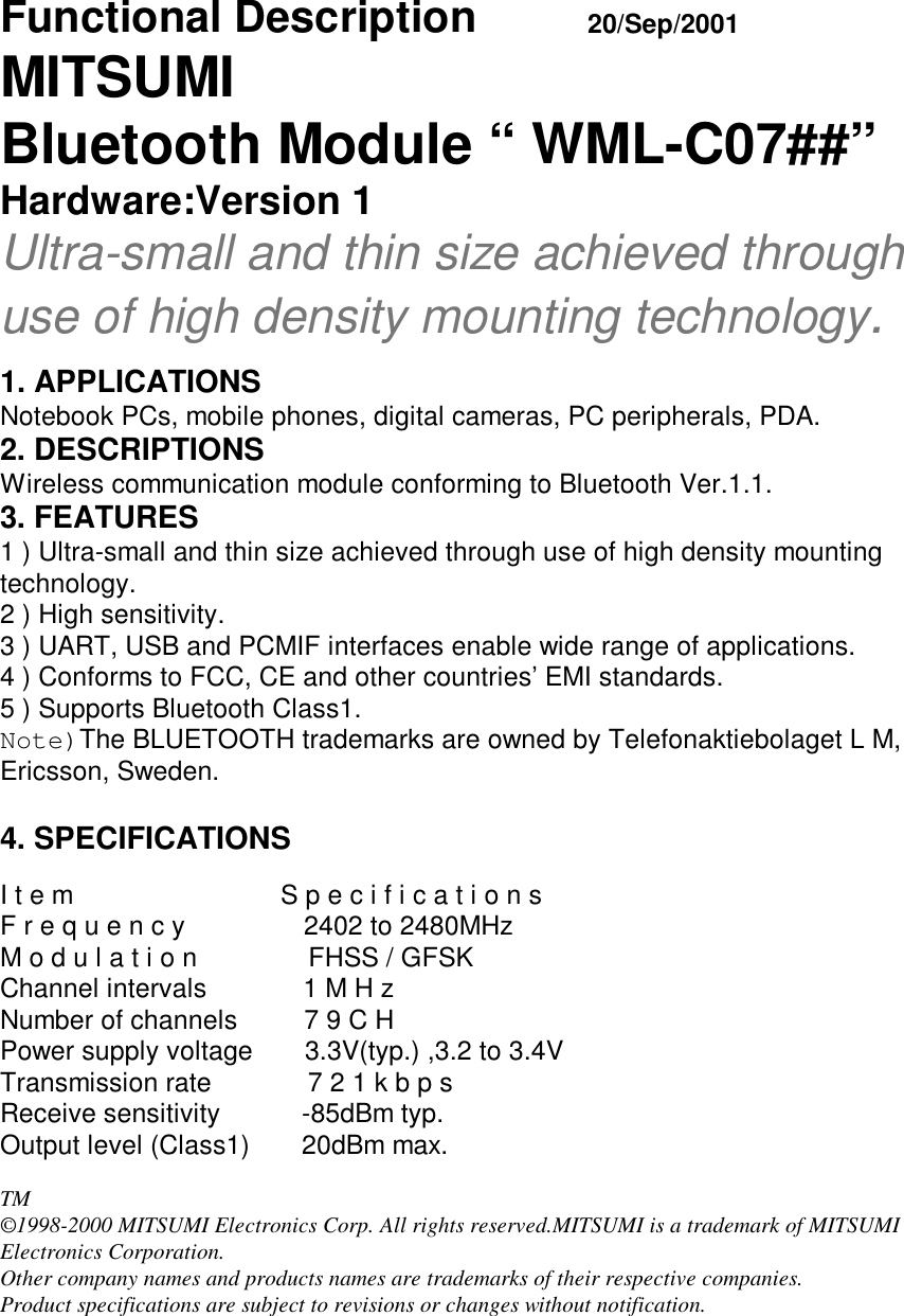
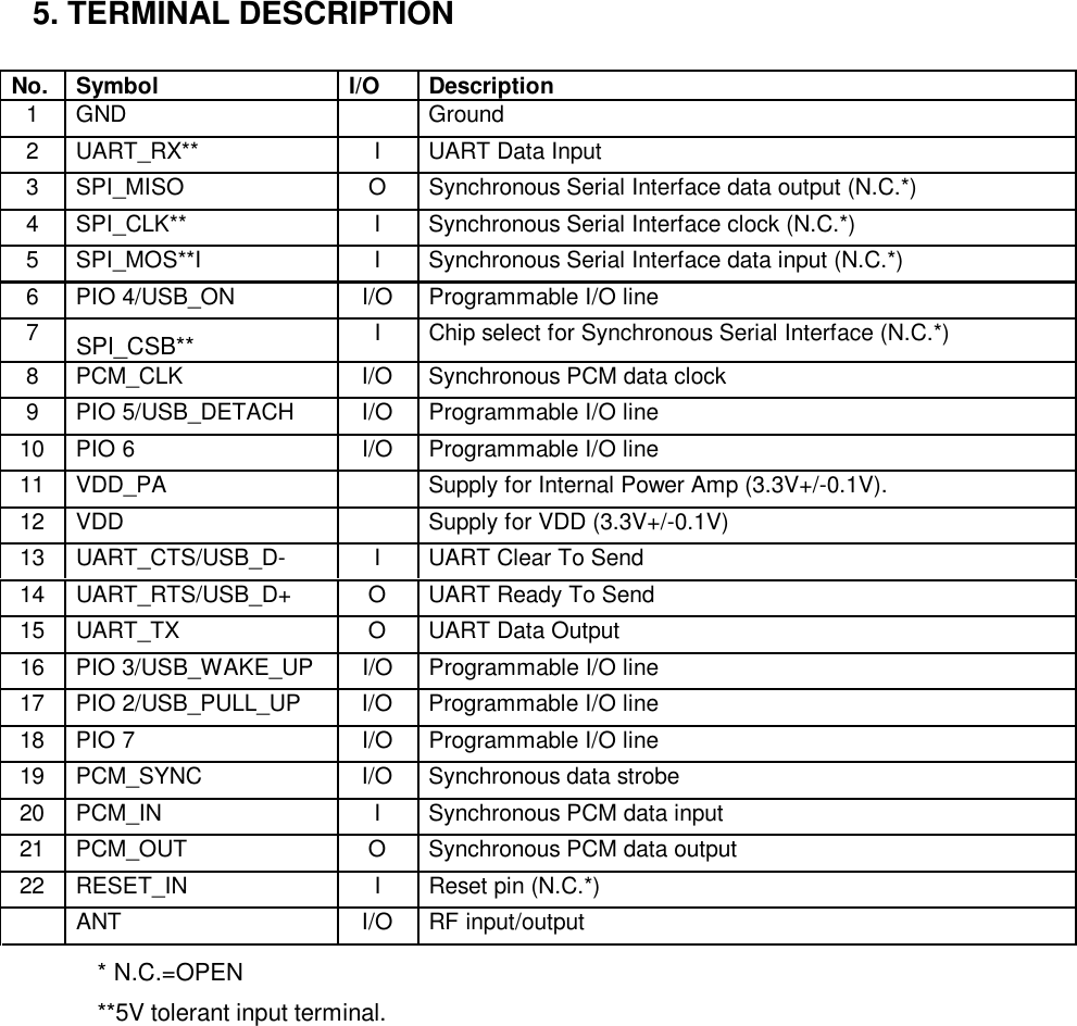
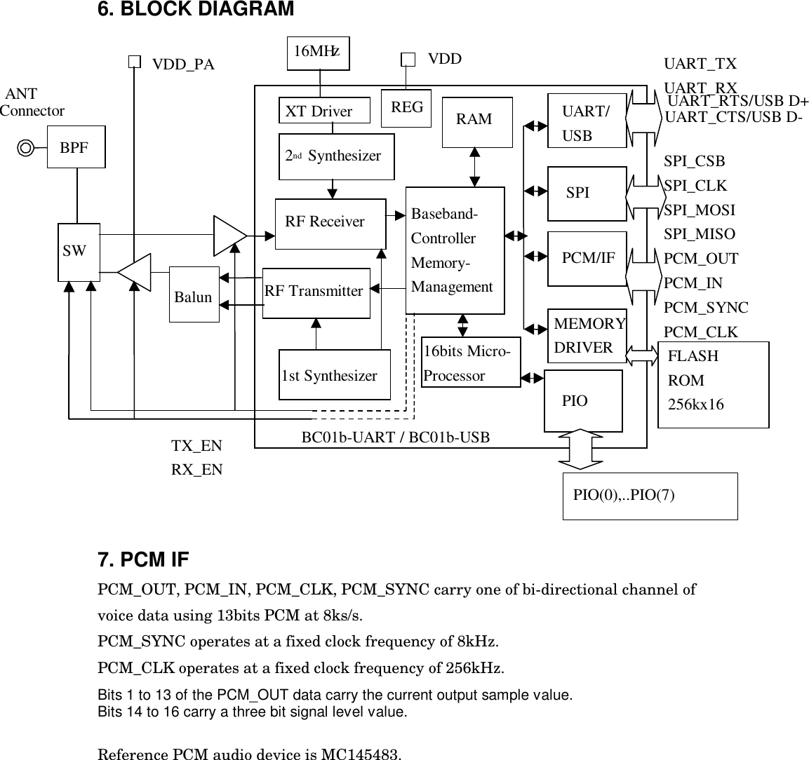
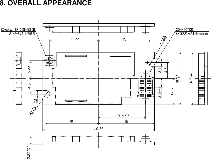
functional description
Navigation menu
Upload a User Manual
Namespaces
Wiki Guide
HTML
PDF
Info
Views
User Manual
Discussion / Help
Navigation