Mojo Networks C-65 Access Point / Sensor User Manual AirTight Management Console User s Guide
AirTight Networks, Inc. Access Point / Sensor AirTight Management Console User s Guide
Contents
User Guide rev
User Guide
AirTight Management Console
Version 7.1 Update 5
This page is intentionally left blank

END USER LICENSE AGREEMENT
Please read the End User License Agreement before installing AirTight Management Console/AirTight
Wi-Fi/AirTight WIPS. The End User License Agreement is available at the following location
http://www.airtightnetworks.com/fileadmin/pdf/AirTight-EULA.pdf.
Installing AirTight Management Console/AirTight Wi-Fi/AirTight WIPS constitutes your acceptance of the
terms and conditions of the End User License Agreement.
DISCLAIMER
THE INFORMATION IN THIS GUIDE IS SUBJECT TO CHANGE WITHOUT ANY PRIOR NOTICE.
AIRTIGHT® NETWORKS, INC. IS NOT LIABLE FOR ANY SPECIAL, INCIDENTAL, INDIRECT, OR
CONSEQUENTIAL DAMAGES WHATSOEVER (INCLUDING, WITHOUT LIMITATION, DAMAGES FOR
LOSS OF BUSINESS PROFITS, BUSINESS INTERRUPTION, LOSS OF BUSINESS INFORMATION,
OR ANY OTHER PECUNIARY LOSS) ARISING OUT OF THE USE OF OR INABILITY TO USE THIS
PRODUCT.
THIS PRODUCT HAS THE CAPABILITY TO BLOCK WIRELESS TRANSMISSIONS FOR THE
PURPOSE OF PROTECTING YOUR NETWORK FROM MALICIOUS WIRELESS ACTIVITY. BASED
ON THE POLICY SETTINGS, YOU HAVE THE ABILITY TO SELECT WHICH WIRELESS
TRANSMISSIONS ARE BLOCKED AND, THEREFORE, THE CAPABILITY TO BLOCK AN EXTERNAL
WIRELESS TRANSMISSION. IF IMPROPERLY USED, YOUR USAGE OF THIS PRODUCT MAY
VIOLATE US FCC PART 15 AND OTHER LAWS. BUYER ACKNOWLEDGES THE LEGAL
RESTRICTIONS ON USAGE AND UNDERSTANDS AND WILL COMPLY WITH US FCC
RESTRICTIONS AS WELL AS OTHER GOVERNMENT REGULATIONS. AIRTIGHT IS NOT
RESPONSIBLE FOR ANY WIRELESS INTERFERENCE CAUSED BY YOUR USE OF THE PRODUCT.
AIRTIGHT NETWORKS, INC. AND ITS AUTHORIZED RESELLERS OR DISTRIBUTORS WILL
ASSUME NO LIABILITY FOR ANY DAMAGE OR VIOLATION OF GOVERNMENT REGULATIONS
ARISING FROM YOUR USAGE OF THE PRODUCT, EXCEPT AS EXPRESSLY DEFINED IN THE
INDEMNITY SECTION OF THIS DOCUMENT.
LIMITATION OF LIABILITY
AirTight Networks will not be liable to customer or any other party for any indirect, incidental, special,
consequential, exemplary, or reliance damages arising out of or related to the use of AirTight Wi-Fi,
AirTight WIPS, AirTight Cloud Services, and AirTight devices under any legal theory, including but not
limited to lost profits, lost data, or business interruption, even if AirTight Networks knows of or should
have known of the possibility of such damages. Regardless of the cause of action or the form of action,
the total cumulative liability of AirTight Networks for actual damages arising out of or related to the use of
AirTight Wi-Fi, AirTight WIPS, AirTight Cloud Services or AirTight devices will not exceed the respective
price paid for AirTight Wi-Fi, AirTight WIPS, AirTight Cloud Services, or AirTight devices.
Copyright © 2013-2015 AirTight® Networks, Inc. All Rights Reserved.
Powered by Marker PacketTM, Active ClassificationTM, Live EventsTM, VLAN Policy MappingTM, Smart
ForensicsTM, WEPGuardTM and WPAGuardTM. AirTight Networks and the AirTight Networks logo are
trademarks and AirTight is a registered trademark of AirTight Networks, Inc.
This product contains components from Open Source software. These components are governed by the
terms and conditions of the GNU Public License. To read these terms and conditions visit
http://www.gnu.org/copyleft/gpl.html.
Protected by one or more of U.S. patent Nos. 7,002,943; 7,154,874; 7,216,365; 7,333,800; 7,333,481;
7,339,914; 7,406,320; 7,440,434; 7,447,184; 7,496,094; 7,536,723; 7,558,253; 7,710,933; 7,751,393;
7,764,648; 7,804,808; 7,856,209; 7,856,656; 7,970,894; 7,971,253; 8,032,939; and international patents:
AU 200429804; GB 2410154; JP 4639195; DE 60 2004 038 621.9; and GB/NL/FR/SE 1976227. More
patents pending. For more information on patents, please visit: www.airtightnetworks.com/patents
i
Table of Contents
About This Guide .......................................................................................................................................... 1
Intended Audience ..................................................................................................................................... 1
Product and Documentation Updates ....................................................................................................... 1
Contact Information ................................................................................................................................... 1
Introduction.................................................................................................................................................... 3
AirTight Management Console Configuration ............................................................................................... 7
Configure Language Setting ...................................................................................................................... 7
Set System Language............................................................................................................................ 7
Set SSID encoding ................................................................................................................................. 7
Copy Language Setting to Another Server ............................................................................................ 8
Configure Time Zone and Tag for Location ............................................................................................... 8
Set Time Zone ....................................................................................................................................... 8
Edit Time Zone ....................................................................................................................................... 8
Set Location Tag ................................................................................................................................... 9
User Management ..................................................................................................................................... 9
Configure Password Policy .................................................................................................................. 12
Configure Account Suspension Setting ............................................................................................... 13
Configure Login Parameters ................................................................................................................ 14
User Authentication ................................................................................................................................. 16
Configure LDAP Server Parameters .................................................................................................... 16
Configure RADIUS Parameters ........................................................................................................... 18
Configure Parameters for Certificate-based authentication................................................................. 20
Wireless Intrusion Prevention System ..................................................................................................... 22
Manage Authorized WLAN Policy ........................................................................................................ 23
Configure AP Auto-classification Policy ............................................................................................... 25
Configure Client Auto-classification Policy .......................................................................................... 26
Intrusion Prevention ............................................................................................................................. 30
Activate Intrusion Prevention for Location ........................................................................................... 32
Import Device List ................................................................................................................................ 33
Manage Banned Device List ................................................................................................................ 35
Manage Hotspot SSIDs ....................................................................................................................... 36
Manage Vulnerable SSIDs .................................................................................................................. 38
Manage Smart Device Types .............................................................................................................. 39
Manage WiFi Access ............................................................................................................................... 41
Manage SSID Profiles.......................................................................................................................... 41
Manage Mesh Profiles ......................................................................................................................... 82
Configure Event Notification ................................................................................................................ 87
AirTight Management Console User Guide
ii
Activate Event Generation for Location ............................................................................................... 88
Configure Email Recipients ................................................................................................................. 89
Configure Device - Server Communication Settings ............................................................................... 89
Use Key for Device - Server Communication ...................................................................................... 89
Use Passphrase for Device - Server Communication ......................................................................... 89
Reset Communication Key .................................................................................................................. 89
Manage Policy Templates ....................................................................................................................... 90
Add Policy Template ............................................................................................................................ 90
Edit Policy Template ............................................................................................................................ 91
Search Policy Template ....................................................................................................................... 92
Copy Policy Template to Another Location ......................................................................................... 93
Save Policy Template with a Different Name ...................................................................................... 93
Print Policy Template List .................................................................................................................... 93
Delete Policy Template ........................................................................................................................ 93
Manage Authorized WLAN Policy ........................................................................................................... 94
Configure Authorized WLAN Policy ..................................................................................................... 95
Edit Authorized WLAN Policy .............................................................................................................. 95
View High Availability Status for Server .................................................................................................. 96
View/Upgrade License Details ................................................................................................................ 97
Manage Look and Feel of Reports .......................................................................................................... 98
Customize Report Header Text ........................................................................................................... 98
Customize Summary Table ................................................................................................................. 98
Customize Section Results .................................................................................................................. 99
Restore Default Look and Feel Settings .............................................................................................. 99
Copy Reports Look and Feel Settings to Another Server .................................................................... 99
Configure NTP ....................................................................................................................................... 100
Check Time Drift between AirTight server and NTP server............................................................... 100
Synchronize AirTight Server Time with NTP Server .......................................................................... 100
Disable NTP ....................................................................................................................................... 100
Configure RF Propagation Settings ....................................................................................................... 100
Restore RF Propagation Defaults ...................................................................................................... 102
Copy RF Propagation Setting to Another Server ............................................................................... 102
Configure Live RF View Setting ............................................................................................................ 103
Restore Default Live RF View Settings.............................................................................................. 103
Copy Live RF View Setting to Another Server ................................................................................... 103
Configure Location Tracking.................................................................................................................. 104
Restore Location Tracking Configuration Defaults ............................................................................ 104
Copy Location Tracking Configuration to Another Server ................................................................. 104
Manage Auto Location Tagging ............................................................................................................ 105
Table of Contents
iii
Restore Auto Location Tagging Defaults ........................................................................................... 105
Copy Auto Location Tagging Settings to Another Server .................................................................. 106
Set up and Manage Server Cluster ....................................................................................................... 107
Benefits of Server Cluster .................................................................................................................. 107
Create and Manage Server Cluster ................................................................................................... 108
Manage Child Servers from Parent Server in Server Cluster ............................................................ 115
Manage Vendor OUIs ............................................................................................................................ 119
Add Vendor or MAC Prefix ................................................................................................................ 119
Delete Vendor or MAC Prefix ............................................................................................................ 119
Manage Device Template...................................................................................................................... 119
Customize Policy/Device Template for Location ............................................................................... 121
Revert to Inherited Device Template ................................................................................................. 121
Add Device Template......................................................................................................................... 122
Edit Device Template ......................................................................................................................... 128
Search Device Template ................................................................................................................... 128
Copy Device Template....................................................................................................................... 128
Print Device Template List for Location ............................................................................................. 129
Delete Device Template..................................................................................................................... 129
Configure SMTP Settings ...................................................................................................................... 129
Restore SMTP Configuration Defaults ............................................................................................... 130
Test SMTP Settings ........................................................................................................................... 131
Copy SMTP Configuration to Another Server .................................................................................... 131
View System Status ............................................................................................................................... 131
Start/Stop Server ............................................................................................................................... 132
Upgrade Server ..................................................................................................................................... 132
Configure Auto Deletion Settings .......................................................................................................... 133
Copy Auto Deletion Settings to Another Server ................................................................................ 134
Manage Audit Log Settings ................................................................................................................... 135
Set Duration for Audit Log Download ................................................................................................ 135
Download Audit Logs ......................................................................................................................... 135
Restore Default User Action Log Download Settings ........................................................................ 135
Copy Audit Log Settings to Another Server ....................................................................................... 136
Configure Integration with Enterprise Security Management Servers .................................................. 137
Syslog Integration .............................................................................................................................. 137
Arcsight Integration ............................................................................................................................ 138
SNMP Integration ............................................................................................................................... 140
Manage WLAN Integration .................................................................................................................... 142
WLAN Integration ............................................................................................................................... 142
Manage Integration with Aruba Mobility Controllers .......................................................................... 142
AirTight Management Console User Guide
iv
Configure Integration with HP MSM Controller .................................................................................. 145
Manage Integration with Cisco WLC ................................................................................................. 148
Manage Integration with Meru ........................................................................................................... 151
Manage AirTight Mobile Clients ............................................................................................................ 152
AirTight Mobile Settings ..................................................................................................................... 152
Manage AirTight Mobile Clients ......................................................................................................... 153
Add AirTight Mobile Group Manually ................................................................................................. 157
Edit AirTight Mobile Group ................................................................................................................. 157
Attach Policy to AirTight Mobile Group .............................................................................................. 158
Overwrite Existing Policy for AirTight Mobile Group .......................................................................... 158
Detach Policy from AirTight Mobile Group......................................................................................... 158
View AirTight Mobile Group Policy in HTML Format ......................................................................... 158
View AirTight Mobile Group Policy in XML Format ............................................................................ 159
Activate Automatic Client Grouping ................................................................................................... 159
Apply Default Policy to New Groups .................................................................................................. 159
Print List of AirTight Mobile Groups for Location ............................................................................... 159
Delete AirTight Mobile Group ............................................................................................................ 160
Dashboard ................................................................................................................................................. 161
Add a page to dashboard ...................................................................................................................... 161
Delete a page from dashboard .............................................................................................................. 162
Print dashboard page ............................................................................................................................ 162
WIPS Widgets ....................................................................................................................................... 162
Network Widgets ................................................................................................................................... 163
Client Widgets ....................................................................................................................................... 165
Access Point Widgets ............................................................................................................................ 165
Devices ...................................................................................................................................................... 167
AirTight Devices .................................................................................................................................... 167
Device Properties ............................................................................................................................... 168
View Visible LANs .............................................................................................................................. 173
View Visible APs ................................................................................................................................ 173
View Visible Clients ............................................................................................................................ 173
View Active APs ................................................................................................................................. 173
View Active Clients ............................................................................................................................ 173
View AirTight Device Events .............................................................................................................. 173
View Channel Occupancy .................................................................................................................. 173
View Interference ............................................................................................................................... 174
View Mesh Network Links .................................................................................................................. 174
Search AirTight Devices .................................................................................................................... 174
Sort AirTight Devices ......................................................................................................................... 174
Table of Contents
v
Change Location ................................................................................................................................ 174
Print AirTight Device Information for Location ................................................................................... 174
Reboot Device ................................................................................................................................... 175
Troubleshoot Device .......................................................................................................................... 175
Upgrade or Repair Device ................................................................................................................. 178
Enable Pagination for AirTight Device Listing and Set Page Size .................................................... 178
Disable Pagination for AirTight Device Listing ................................................................................... 180
Add Custom Filter .............................................................................................................................. 180
Edit Custom Filter .............................................................................................................................. 180
Delete Custom Filter .......................................................................................................................... 181
Delete Device ..................................................................................................................................... 181
Monitor Clients ....................................................................................................................................... 181
View Client Properties........................................................................................................................ 183
View Recently Associated APs/Ad hoc networks .............................................................................. 185
View Events related to Client ............................................................................................................. 185
View Client Retransmission Rate Trend ............................................................................................ 185
View Devices Seeing Client ............................................................................................................... 185
View Client Average Data Rate ......................................................................................................... 186
View Client Traffic .............................................................................................................................. 186
Change Client Location...................................................................................................................... 186
Quarantine Client ............................................................................................................................... 186
Disable Auto Quarantine/Exclude Device from Intrusion Prevention Policy ...................................... 186
Add to banned list .............................................................................................................................. 187
Classify / Declassify as Smart Device ............................................................................................... 187
Change Client Category..................................................................................................................... 187
Reset Data Transmitted by Client ...................................................................................................... 187
Locate Client ...................................................................................................................................... 187
View Recently Probed SSIDs ............................................................................................................ 187
Troubleshoot Client ............................................................................................................................ 188
Debug Client Connection Problems ................................................................................................... 191
Download Connection Log ................................................................................................................. 192
Delete Connection Log History .......................................................................................................... 193
Enable Pagination for Client Listing and Set Page Size .................................................................... 194
Disable Pagination for Client Listing .................................................................................................. 194
Add Custom Filter .............................................................................................................................. 194
Edit Custom Filter .............................................................................................................................. 195
Delete Custom Filter .......................................................................................................................... 195
Print Client List for Location ............................................................................................................... 195
Delete Client ...................................................................................................................................... 196
AirTight Management Console User Guide
vi
Spectrogram .......................................................................................................................................... 196
Monitor Access Points (APs) ................................................................................................................. 196
View AP Properties ............................................................................................................................ 198
View Recently Associated Clients ..................................................................................................... 201
View AP Utilization ............................................................................................................................. 201
View AP Associated Clients ............................................................................................................... 202
View AP Traffic .................................................................................................................................. 202
View AP Average Data Rate .............................................................................................................. 202
View Devices Seeing AP ................................................................................................................... 202
View AP Events ................................................................................................................................. 202
Change AP Location .......................................................................................................................... 202
Locate AP .......................................................................................................................................... 203
Quarantine an AP .............................................................................................................................. 203
Change AP Category ......................................................................................................................... 203
Disable Auto Quarantine .................................................................................................................... 203
Add to banned list .............................................................................................................................. 203
Sort APs ............................................................................................................................................. 203
Filter AP Details ................................................................................................................................. 204
Search APs ........................................................................................................................................ 204
Enable Pagination for AP Listing and Set Page Size ........................................................................ 204
Disable Pagination for AP Listing ...................................................................................................... 205
Add Custom Filter .............................................................................................................................. 205
Edit Custom Filter .............................................................................................................................. 205
Delete Custom Filter .......................................................................................................................... 206
Print AP List for Location ................................................................................................................... 206
Merge APs ......................................................................................................................................... 206
Split AP .............................................................................................................................................. 207
Troubleshoot AP ................................................................................................................................ 207
Delete AP ........................................................................................................................................... 210
Monitor Networks ................................................................................................................................... 211
Manage Locations and Location Layout ................................................................................................... 215
Define Location Tree ............................................................................................................................. 215
Add Location .......................................................................................................................................... 217
Edit Location .......................................................................................................................................... 217
Move Location ....................................................................................................................................... 218
Delete Location ...................................................................................................................................... 218
Search Locations ................................................................................................................................... 218
Add Layout ............................................................................................................................................ 218
Edit Layout ............................................................................................................................................. 219
Table of Contents
vii
Delete Layout ........................................................................................................................................ 220
Show / Hide Location List ...................................................................................................................... 220
Show/Hide Devices on Location Layout ................................................................................................ 220
Place Devices/Locations on Location Layout ........................................................................................ 220
Remove Devices/Locations from Location Layout ................................................................................ 221
View RF Coverage / Heat Maps ............................................................................................................ 221
View AP Coverage ............................................................................................................................. 222
View AP Coverage by RSSI Value .................................................................................................... 222
View Sensor Coverage ...................................................................................................................... 222
View AP Link Speed .......................................................................................................................... 223
View AP Channel Coverage .............................................................................................................. 223
Calibrate RF Views ................................................................................................................................ 223
Zoom in / Zoom out Layout.................................................................................................................... 224
Adjust the Layout Opacity...................................................................................................................... 224
Add Note ................................................................................................................................................ 224
Edit Note ................................................................................................................................................ 225
Move Note ............................................................................................................................................. 225
Hide Notes ............................................................................................................................................. 225
Show Notes ........................................................................................................................................... 225
View Mesh Topology ............................................................................................................................. 226
Hide Mesh Topology .............................................................................................................................. 226
View and Manage Events ......................................................................................................................... 227
View Events for Location ....................................................................................................................... 228
View Deleted Events for Location ......................................................................................................... 228
Change Event Location ......................................................................................................................... 228
Acknowledge Event ............................................................................................................................... 229
Turn on Vulnerability Status for Event ................................................................................................... 229
Turn off Vulnerability Status for Event ................................................................................................... 229
Mark Event as Read .............................................................................................................................. 229
Mark Event for Deletion ......................................................................................................................... 229
Enable Pagination for Event Listing and Set Page Size ....................................................................... 230
Disable Pagination for Event Listing ...................................................................................................... 230
Add Custom Filter .................................................................................................................................. 230
Edit Custom Filter .................................................................................................................................. 231
Delete Custom Filter .............................................................................................................................. 231
Print Event List for Location................................................................................................................... 231
Forensics ................................................................................................................................................... 233
View AP based /Client based Threat Details......................................................................................... 233
View Event Summary......................................................................................................................... 234
AirTight Management Console User Guide
viii
View Participating Devices and Quarantine Status ........................................................................... 234
Locate Participating Device ............................................................................................................... 235
View Administration Action Logs for Event ........................................................................................ 236
Acknowledge Event ........................................................................................................................... 236
Change Location of the Event ........................................................................................................... 236
Turn Vulnerability On/Off ................................................................................................................... 237
Print Event List for Location ............................................................................................................... 237
Mark Event for Deletion ..................................................................................................................... 237
Mark Event as Read .......................................................................................................................... 237
Show/Hide Deleted Events ................................................................................................................ 238
Reports ...................................................................................................................................................... 239
Analytics ................................................................................................................................................ 248
Manage Report Archive ......................................................................................................................... 250
Fetch Archived Report ....................................................................................................................... 251
Rename Archived Report .................................................................................................................. 251
Print Archived Report List for Location .............................................................................................. 251
Delete Archived Report ...................................................................................................................... 251
Schedule Report Generation ................................................................................................................. 251
Send report by e-mail......................................................................................................................... 255
Archive report ..................................................................................................................................... 255
View Report Schedules ......................................................................................................................... 255
Glossary of Icons ...................................................................................................................................... 257
1
About This Guide
The AirTight Management Console User Guide explains how to configure and manage the AirTight
Management Console .
Important! Please read the EULA before installing AirTight WIPS or AirTight Wi-Fi. Installing AirTight
WIPS or AirTight Wi
-Fi constitutes your acceptance of the terms and conditions of the EULA mentioned
above in this document.
Intended Audience
This guide is intended for anyone who wants to configure and use AirTight WIPS or AirTight Wi-Fi or use
AirTight Cloud Services.
Product and Documentation Updates
To receive important news on product updates, please visit our website at
http://www.airtightnetworks.com.
We continuously enhance our product documentation based on customer feedback. To obtain a latest
copy of this document, visit http://www.airtightnetworks.com/home/support.html.
Contact Information
AirTight® Networks, Inc.
339 N, Bernardo Avenue, Suite #200,
Mountain View, CA 94043
Tel: (650) 961-1111
Fax: (650) 963-3388
For technical support, send an email to support@airtightnetworks.com
3
Introduction
AirTight Management Console is a HTML 5 based user interface using which you can configure and
monitor AirTight WIPS and/or AirTight Wi-Fi server to access the AirTight Cloud Services.
HTML 5 makes AirTight Management Console compatible with most browsers and operating systems.
AirTight Management Console is intuitive and easy to use. It can be configured with ease to suit your
WIPS and/or Wi-Fi needs.
The Console is divided into 7 sections - Dashboard, Locations, Devices, Events, Forensics,
Configuration, and Reports.
AirTight Management Console can be configured from the Configuration section. You can define and
manage users, configure and manage WIPS settings, Wi-Fi access settings, integration settings for
WLAN, integration settings for enterprise security management servers etc from the configuration section.
The Dashboard section provides a graphical view of the WIPS and/or Wi-Fi implementation. It offers you
the flexibility to choose from a good number of graphs related to the access points, clients on your
wireless network, as well as the networks detected by WIPS sensors. Details of wireless threats to the
network can be seen on the WIPS widgets.
Apart from the pie chart or bar graph representation, the widget data can be viewed as a tabular
representation by clicking the icon present on the top of widgets. You can alternate between tabular
view and pie chart/bar graph view. This means that if you are in the pie/graph view, you will see the
icon. If you are in the table view, you will see the or icon, depending on whether the alternate
view is represented as a pie chart or bar graph.
The widget data is presented in the last-viewed format when you log in to AirTight Management Console
the next time.
AirTight Management Console facilitates the creation of locations. These locations could be various
buildings in your campus or the different floors or levels in your office space. You can create and manage
your retail or office locations using the Locations section. You can attach a layout to each floor in the
office space. You can then define WIPS / Wi-Fi policies specific to these locations.
All APs, AirTight devices, sensors, smart devices are seen under the Devices section. Apart from the
actual devices, the devices section also displays a list of networks detected by the WIPS sensors.
The Events section displays the events detected by the WIPS implementation.
The Forensics section lists AP-based threats and client-based threats in a user friendly format. You can
drill down into the wireless threats using the forensics section.
The Reports section facilitates generation of various built-in and custom reports. These reports comprise
various compliance reports and reports related to devices in the network and events occurring in the
network. You can schedule reports and generate analytics data using the Reports section.
Following are the salient features of the AirTight Management Console.
•
Intuitive, portable and easy-to-use HTML5 UI
AirTight Management Console User Guide
4
HTML5 makes AirTight Management Console compatible with most browsers and operating
systems. It can be operated using tablets and other smart devices as well. The interface is intuitive
and can be used and configured without much effort.
•
Fully user-customizable dashboards and screens
The dashboard offers you the flexibility to choose from a good number of graphs displaying access
point, client, network, and WIPS statistics.
Graphs are seen in widgets. You can have multiple dashboards on the console. Each dashboard
can have multiple widgets based on your requirement, with widget repetition allowed.
The widget classification is very intuitive. The widgets are classified as network widgets, access
point widgets, client widgets and WIPS widgets.
In all other sections of the UI, you can filter the information or columns visible in the respective
section, based on your requirement.
You also have the option to view information in various text and graphical format in some of the
sections. For example, the Forensics section displays information in text and pie chart formats. In
the Reports section, you can customize the reports as required. Standard compliance reports are
also available.
You can customize filters on device and event listings under Devices and Events respectively.
You can add, edit and delete custom filters on device and event listings. You can define multiple
filters on devices and events listings and save them. These will be retained until you delete them.
When you apply a filter to device or event listing during a login session, the filtered list is retained
till the end of the session.
•
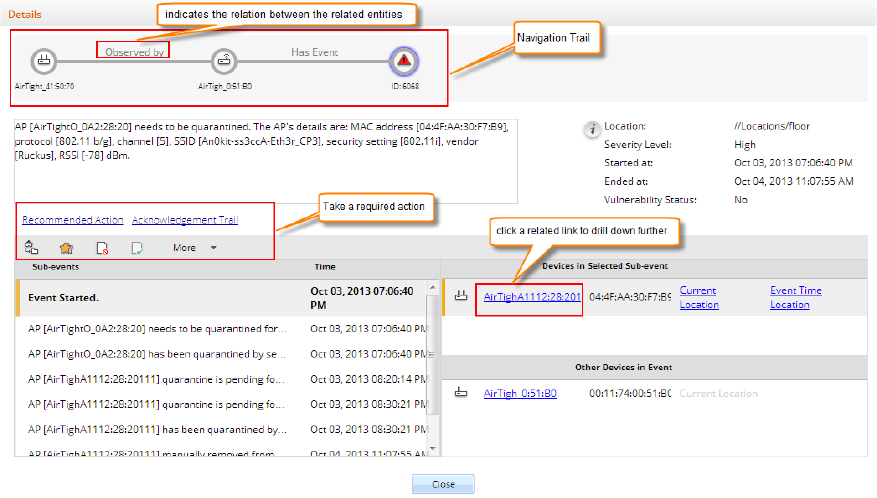
Innovative drill down with navigation trail on any event, chart or device
AirTight Management Console provides a unique feature with which you can delve deeper or drill
down to events or devices from any section of the console where they are visible. The devices and
events are seen as links across AirTight Management Console. You can click on the link to view
the details of the respective event or device and the related devices or events. You can also take
the required actions if you have the privilege to take those actions. Thus, you can hop across
different sections by clicking the links for devices and events. When you navigate across pages in
this way, a navigation trail is displayed at the top of the currently viewed page or screen. This is
extremely useful for you to understand the path you have taken to drill down to the desired page.
The navigation trail also makes it convenient for you to navigate back to one of the screens or
pages in the navigation trail.
See the image below for a sample drill down with a navigation trail.
Introduction
5
•
Rich Visualization of Heat maps
You can view radio frequency heat maps in various views. The AP coverage view is useful to find
out the available signal strength at each point. The sensor coverage view enables you to view the
detection and prevention zones of visibility for selected sensors. The color-coding scheme used
enhances the readability of the heat maps.
•
Hierarchical management architecture ideal for geographically distributed sites
AirTight Management Console provides for hierarchical management of geographically distributed
sites. You can create a hierarchy of locations or a location tree. Each location folder could
represent a country and a child location folder could represent a state. These location folders could
then have city locations as child location folders. One of more buildings in the city office campus
can be represented as child location folders under the respective city location folders. Individual
floors or levels in the office space can be represented by location floors under the location folders
that represent buildings.
You can then define Wi-Fi/WIPS policies specific to each location. You can apply a common policy
to the location folders. These policies are automatically inherited by the child locations. This makes
management of related locations easy and convenient at the click of a button.
•
Role-based administration and extensible configuration framework
The administration and operation of the Wi-Fi or WIPS solution through AirTight Management
Console is role-based. A user has restricted access to one or more locations that he is associated
with. He is able to view information and configure the console related to these locations only.
Information from other locations are not visible to him. A user is able to perform operations based
on his role. AirTight Management Console provides four distinct user roles-superuser,
administrator, operator and viewer.
•
Configuration Wizard
When a user logs in to AirTight Management Console, and navigates to Dashboard or Events for
the first time, a configuration wizard guides the user on how to use these functionalities. The
wizard is functional only during the first time view.
7
AirTight Management Console
Configuration
AirTight Management Console needs to be configured appropriately for use, before it can start monitoring
and/or protecting the network. Click Configuration to view the various options to configure in AirTight
Management Console.
The Configuration page displays various categories - Device Configuration, WIPS, User Accounts,
Events and System Settings, AirTight Mobile, ESM Integration.
Device Configuration: Configure and manage the SSID profiles using Device Configuration>SSID
Profiles. The SSID profiles can then be attached to the device templates.
Configure and manage the device templates using Device Configuration>Device Template. These
device templates can then be applied to various devices.
WIPS: Configure and manage the wireless intrusion prevention parameters using WIPS.
User Accounts: User management, password management, LDAP, RADIUS configuration, certificate
configuration, account suspension management is done using User Accounts.
Events: Configure and manage event related settings, e-mail notification on occurrence of certain critical
events using Events.
System Settings: Configure and manage AirTight server-related settings using System Settings.
AirTight Mobile: Configure AirTight Mobile integration settings using AirTight Mobile.
ESM Integration: Configure settings for integration with Enterprise Security Management software using
ESM Integration. AirTight Management Console integrates with SNMP, Syslog and Arcsight.
Configure Language Setting
Define the system language and the SSID encoding using the Configuration>Language Setting option.
This setting is used to set the language for email communication, Syslog messages etc.
You can copy language setting from one server to another when the servers are part of the same server
cluster.
Set System Language
The system language is the default language that the system will use to communicate via emails, syslog
messages etc. If you want to use a language other than English as the system language for AirTight
Management Console, the language of your choice should be defined under Language Setting. The
default value for System Language Preference is English.
Set SSID encoding
Parameters like SSID, when configured on the AP using page encoding (either non-English native
window or using a language pack), appear garbled if the page encoding does not match the encoding
selected here.
AirTight Management Console User Guide
8
Select the appropriate SSID encoding commonly used in your region, in order to correctly see the local
language SSIDs in the system.
The default value for SSID encoding is UTF-8. To select a different SSID encoding, do the following.
1. Go to Configuration>System Settings>Language Setting.
2. Under SSID Encoding, select the required SSID encoding.
3. Click Save to save the new SSID encoding.
Copy Language Setting to Another Server
You can copy the language setting from one server to another server when both servers are part of the
same server cluster. You can copy language setting from child server to child server, parent server to
child server, or child server to parent server. You must be a superuser or an administrator to copy policies
from one server to another.
To copy language settings, do the following.
1. Go to Configuration>System Settings>Language Setting on the parent server.
2. Click Copy Policy. The Copy Policies dialog box appears.
3. Select the server from which language setting is to be copied.
4. Select the server to which the ;language setting is to be copied.
5. Click OK to copy the language setting,
Configure Time Zone and Tag for Location
Set the appropriate time zone for the selected location using the Configuration>System
Settings>Location Specific Attributes page. The time zone settings are specific to individual locations
and cannot be inherited from the parent location. You need administrator privileges to configure the
location time zone for a location.
The time zone settings help in accurate analytics. Make sure to select the correct time zone for the
selected location.
Note that you cannot set a time zone for a location floor because a location floor represents a floor
location in the organization premises. The time zone set for the immediate parent location folder of a
location floor applies to the location floor.
In case you do not set the time zone for a location folder, the analytics data will show the server time
zone in the fields where local time zone is shown.
Set Time Zone
To set the time zone for a location, do the following.
1. Go to Configuration>System Settings>Location Specific Attributes.
2. Select the location for which you want to set the time zone.
3. Select the time zone.
4. Click Save to save the new time zone. Alternatively, if you want to cancel the operation, click Cancel.
Edit Time Zone
To edit the time zone for a location, do the following.
1. Go to Configuration>System Settings>Location Specific Attributes.
2. Select the location for which you want to edit the time zone.
3. Select the new time zone.
AirTight Management Console Configuration
9
4. Click Save to save the new time zone. The changed time zone is applied recursively to all the child
location folders.
Set Location Tag
A location tag is the location identifier that could be appended to the circuit ID when DHCP Option 82 is
enabled for an SSID profile configured for this location.
If '%l 'is used in the circuit ID, the AP replaces it with the location tag.
To set the location tag for a location, do the following.
1. Go to Configuration>System Settings>Location Specific Attributes.
2. Select the location for which you want to set the location tag.
3. Enter the location tag.
4. Click Save to save the changes.
User Management
There are four types of users in AirTight Wi-Fi/AirTight WIPS. They are Superuser, Administrator,
Operator and Viewer.
You can manage user-related operations through Configuration>User Accounts>Users. You can add,
edit, and delete users. You can search users, and print a list of users defined at a location.
You need administrator privileges to manage users in AirTight Management Console.
The following table details the role-wise rights in AirTight Management Console.
Operations
User Roles
Superuser
Administrator
Operator
Viewer
User account management
Set or modify identification and
authentication option (Password only,
Certificate only, Certificate and Password,
Certificate or Password)
Yes
No
No
No
Add and delete users
Yes
No
No
No
View and modify properties of any
user (User Management screens)
Yes
No
No
No
Define password strength, account locking
policy, maximum concurrent sessions for all
users
Yes
No
No
No
View and modify User Preferences (email,
password, session timeout)
Yes (self
only)
Yes (self
only)
Yes (self
only)
Yes (self
only)
User actions audit
Download user actions audit log
Yes
No
No
No
Modify user actions audit lifetime
Yes
No
No
No
System settings and operating policies
Modify system settings and operating
policies (all settings under Configuration tab
other than User Management, Logs, Login
configuration)
Yes
Yes
No
No
Events, devices and locations
View generated events
Yes
Yes
Yes
Yes
Modify and delete generated events
Yes
Yes
Yes
No
AirTight Management Console User Guide
10
View devices
Yes
Yes
Yes
Yes
Add, delete, and modify devices (APs,
Clients, Sensors)
Yes
Yes
Yes
No
View locations
Yes
Yes
Yes
Yes
Add, delete, and modify locations
Yes
Yes
Yes
No
Calibrate location tracking
Yes
Yes
Yes
No
Reports
Add, delete, modify Shared Report
Yes (all)
Yes (only
self created)
Yes
(only self
created)
No
Generate Shared Report
Yes
Yes
Yes
Yes
Schedule Shared Report
Yes
Yes
Yes
No
Add, delete, modify, generate, schedule My
Report
Yes (only
self
created)
Yes (only
self created)
Yes
(only self
created)
No
Add User
To add a user, do the following.
1. Go to Configuration>User Accounts>Users.
2. Select the location for which you want to add the user.
3. Click the Add User hyperlink. The Add New User dialog box appears.
The following table describes the fields on the Add New User page.
Field
Description
User Type
Specifies the type of user.
Login ID
Specifies the login id of the user.
Role
Specifies the role assigned to the user. Choose from
Viewer, Operator, Administrator and Super User.
First Name
Specifies the first name of the user.
Last Name
Specifies the last name of the user.
Password
Specifies the password of the user. Password should be
a combination of letters, numerals and special
characters.
Confirm
Password
Specifies the same password as typed in the password
field to confirm the password.
Email
Specifies the e-mail id of the user.
Allowed
Locations
Specifies the locations for which the user can operate.
Click Change hyperlink to modify the list of allowed
locations. A user can operate on one or more locations.
For instance, an administrator user could have rights to
multiple locations.
Pas
sword Expiry
Specifies if the password expires or does not expire. By
default, the password never expires. Click Change
hyperlink to set an expiry for the password.
Password Expiry
Duration
Specifies the duration in days from the time of change of
the password after which the password expires.
Password Expiry
Warning
Specifies the time in days before the password expiry to
prompt the user to change the password.
Session Timeout
Specifies the idle time interval after which the user's User

AirTight Management Console Configuration
11
Interface (UI) session should be timed out. Two options
are available. Select Never Expires
, if you don't want the
session to time out. Select Expires After and specify the
time in minutes (between 10 and 120 minutes) after
which the session should time out.
Time Zone
Specifies the time zone in which the user operates.
Language
Preference
Specifies the language in which the user wants to view
the UI text. The default value is English.
Multi lingual
Specifies if the UI should support multi-lingual font
support.
4. Click Save to save the changes.
Edit User
To edit a user, do the following.
1. Go to Configuration>User Accounts>Users.
2. Select the location for which you want to edit the user.
3. Click the login id hyperlink for the user that you want to edit. The Edit User Details dialog box
appears.
4. Edit the user details.
5. Click Save to save the changes.
Print User List for Location
You can print a list of users defined for a location.
To print a user list for a location, do the following.
1. Go to Configuration>User Accounts>Users.
2. Select the location for which you want to print the user list.
3. Select the columns that you want in the printed list. Click any column name to select or deselect
columns.
4. Click the print icon. The print preview of the user list appears.
5. Click Print to print the list.
Search User
You can search users using the login ID or name of the user.
To delete a user, do the following.
1. Go to Configuration>User Accounts>Users.
2. Select the location for which you want to search user.
3. Enter the login ID string or the name string in the Quick Search box.
4. Press Enter key.
5. The users with login IDs or names matching the search string are displayed. The search string could
be a substring of the login ID or name of the user.
AirTight Management Console User Guide
12
Delete User
To delete a user, do the following.
1. Go to Configuration>User Accounts>Users.
2. Select the location for which you want to delete the user. The user list appears.
3. Click the Delete hyperlink for the user to delete. A message to confirm delete appears.
4. Click Yes to confirm deletion of user.
Configure Password Policy
The Password Policy determines the minimum requirements for system passwords. This policy applies to
all user roles - super user, administrator, operator, and viewer. If you change this policy, older passwords
are not affected. Only passwords created after a policy change are subject to the new policy. This setting
applies only to local authentication and does not apply to LDAP and RADIUS authentication.
You can copy password policy from one server to another when the servers are part of the same server
cluster.
To configure password settings or password policy, do the following.
1. Go to Configuration>User Accounts>Password Policy.
2. Specify the number of characters required for the password. Minimum number of characters is 4,
maximum number of characters is 15.
3. If you want the password to contain at least one numerical character, select the At least one
numerical character required check box.
4. If you want the password to contain at least one special character, select the At least one special
character required check box.
5. Click Save to save the changes made to the page.
Restore Default Password Policy
The default password policy is as follows.
The password length as 6 characters and no numeric or special characters are required in the password.
To configure password settings or password policy, do the following.
1. Go to Configuration>User Accounts>Password Policy.
2. Click Restore Defaults to restore default password policy.
3. Click Save to save the changes.
Copy Password Policy to Another Server
You can copy the password policy from one server to another server when both servers are part of the
same server cluster. You can copy password policy from child server to child server, parent server to child
server, or child server to parent server.
You must be a superuser or an administrator to copy policies from one server to another.
To copy password policy, do the following.
1. Go to Configuration>User Account>Password Policy on the parent server.
2. Click Copy Policy. The Copy Policies dialog box appears.
3. Select the server from which the password policy is to be copied.
AirTight Management Console Configuration
13
4. Select the server to which the password policy is to be copied.
5. Click OK to copy the password policy,
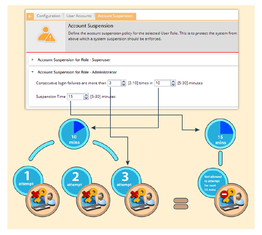
Configure Account Suspension Setting
Account suspension protects the system from spurious logins through dictionary attacks. Define the
account suspension policy using the Configuration>User Accounts>Account Suspension option.
There are four roles available in the system- super user, administrator, viewer and operator. You can
configure different policies for each of these user roles. Configure the suspension time in minutes and the
number of failed login attempts during a specific time duration.
You can copy account suspension setting from one server to another when the servers are part of the
same server cluster.
To configure Account Suspension Setting for a user role, do the following.
1. Go to Configuration>User Accounts>Account Suspension.
1 Specify a suspension time between 5 minutes and 30 minutes, during which the consecutive failed
login attempts happen.
2 Specify the number of failed login attempts between 3 and 10.
3 Click Save to save the changes made to the page.
The following diagrammatic representation explains the account suspension settings.
AirTight Management Console User Guide
14
Account Suspension Settings
This policy is applicable on the root location only.
Copy Account Suspension Settings to Another Server
You can copy the account suspension settings from one server to another server when both servers are
part of the same server cluster. You can copy account suspension settings from child server to child
server, parent server to child server, or child server to parent server. You must be a superuser or an
administrator to copy policies from one server to another.
To copy account suspension settings, do the following.
1. Go to Configuration>User Accounts>Account Suspension on the parent server.
2. Click Copy Policy. The Copy Policies dialog box appears.
3. Select the server from which the account suspension settings are to be copied.
4. Select the server to which the account suspension settings are to be copied.
5. Click OK to copy the account suspension settings,
Configure Login Parameters
AirTight Management Console Configuration
15
You can specify the number of concurrent console logins that a user can have, along with the welcome
message that the user would see on logging on to AirTight Management Console. The user can have up
to 5 concurrent console logins.
You must have administrator privileges to configure login parameters.
You can copy the login configuration from one server to another server when both servers are part of the
same server cluster.
To configure login parameters, do the following.
1. Go to Configuration>System Settings>Login Configuration,
2. Enter the message that the user would see on the login screen, in Configure Login Message.
3. To display the message on the login screen, select the Enable Login Message check box.
4. Specify the number of concurrent sessions per user.
5. Click Save to save the settings.
Restore Defaults for Login Configuration
To restore default settings for login configuration, do the following.
1. Go to Configuration>System Settings>Login Configuration,
2. Click Restore Defaults. Default settings are restored.
3. Click Save to save the changes.
Copy Login Configuration to Another Server
You can copy the login configuration from one server to another server when both servers are part of the
same server cluster. You can copy login configuration from child server to child server, parent server to
child server, or child server to parent server. You must be a superuser or an administrator to copy policies
from one server to another.
To copy login configuration, do the following.
1. Go to Configuration>System Settings>Login Configuration on the parent server.
2. Click Copy Policy. The Copy Policies dialog box appears.
3. Select the server from which the login configuration is to be copied.
4. Select the server to which the login configuration is to be copied.
5. Click OK to copy the login configuration,

AirTight Management Console User Guide
16
User Authentication
Configure LDAP Server Parameters
AirTight Management Console enables you to configure an LDAP server for user authentication. After an
LDAP server is configured, users or groups defined in the LDAP server can login to AirTight Management
Console.
In LDAP configuration, you can configure the following details.
• LDAP Configuration parameters to be able to access the LDAP compliant directory
• LDAP authentication details to search records on the LDAP server
• Privileges for LDAP users- Here you specify the default role and the default locations assigned when
new LDAP users log in, for the case where the role and locations attributes are not provided by the
LDAP server. Note that the default values here apply to all users authenticated via LDAP. If the LDAP
server provides user role and locations attribute at the time of authentication, the attributes provided
by the LDAP server will override the default role and locations attributes.
You must have administrator privileges to configure the LDAP server access parameters.
Configure LDAP Server Access Parameters
To configure LDAP server access parameters, do the following.
1. Go to Configuration>User Accounts>LDAP Configuration option.
2. Select Enable LDAP to enable user authentication using an LDAP compliant directory. All the fields
related to LDAP are enabled on selecting this check box.
3. Enter the connection details as described in the following table.
Field
Description
Primary Server IP
Address/Hostname
The primary server IP address/Hostname of the LDAP
server.
(Primary Server) Port
The primary server port number of the LDAP
server.(Default:389).
Backup Server IP
Address/Hostname
The backup server IP address/Hostname of the LDAP
server.
(Backup Server) Port
The backup server port number of the LDAP server.
En
force Use of SSL/TLS
When this option is checked, only the SSL/TLS connection
to the LDAP server is allowed. When it is not checked,
either of the Open or SSL/TLS connection to the LDAP
server is allowed.
Verify LDAP Server’s Certificate
When this option is selected, the connection to the LDAP
server is not allowed unless the certificate check passes.
When this option is not selected, the connection to the
LDAP server is allowed without verifying the LDAP server
certificate.
4. If you have selected Verify LDAP Server's Certificate, you must add a certificate. Click Add
Certificate to add trusted root CA Certificate(s) for the LDAP server and choose the certificate.
5. Enter the LDAP configuration details as described in the following table.

AirTight Management Console Configuration
17
Field
Description
Base Distinguished Name
The base distinguished name of the directory to which you
want to connect, for example, o=democorp, c=au.
Distinguished Name is a unique identifier of an entry in the
Directory Information Tree (DIT). The name is the
concatenation of Relative Distinguished Names (RDNs)
from the top of the DIT down to the entry in question.
Filter String
This is a mandatory argument. It is a string specifying the
attributes (existing or new) that the LDAP server uses to
filter users. For example, IsUser=A. By specifying a filter
string you can allow or disallow login access to a particular
OU or Group of user defined in the AD.
You can specify a DN (Distinguish Name) of any particular
group to allow access to only those who are member of that
group. For example, memberOf=DC=GroupName,DC=com.
You can include members from multiple groups by using an
OR condition. For example, to allow access to users under
Base DN who are member of any of the two groups, Airtight
Admins OR Airtight Reviewer, you must include the
following filter string:
(|(memberOf=CN=AirTight
Admins,DC=AirTight,DC=Com)(memberOf=CN=Airtight
Reviewer,DC=AirTight,DC=Com))
Similarly, to allow access to users under Base DN who are
member of both Airtight Admins AND Airtight Reviewer
groups, you must include the following filter string:
(&(memberOf=CN=AirTight
Admins,DC=AirTight,DC=Com)(memberOf=CN=Airtight
Reviewer,DC=AirTight,DC=Com))
You can have alternative configurations in AD such as,
adding a new attribute, say ATNWIFI, to the users in AD
that are granted access and then set filter string to allow
users with that attribute only. For example, filter string =
ATNWIFI
You can also create a new group of users in AD with access
granted and include the group in filter string.
The most general filter string you can use is
'objectClass=*'.You can use this string when you do not
want to filter out any LDAP entry.
User ID Attribute
The string defined in the LDAP schema that the system
uses to identify the user.(Default: cn)
6. If the directory does not allow an anonymous search, you must configure user credentials to search
the LDAP compliant directory. Configure the user credentials as described in the following table.
Field
Description
Admin User DN
The DN of the admin user to be used to authenticate in to
the LDAP server.
Append User DN
Select this option if the base DN specified in the LDAP
Configuration Details must be appended to the admin user
DN
Password
The password for the admin user.
AirTight Management Console User Guide
18
•
7. Click Test Settings to test the authentication options.
8. Configure the default role and locations for new LDAP users. They are described in the following
table.
Field
Description
User Role Attribute
The user role attribute string that the system uses to identify
a user’s role, as defined in the LDAP schema.
User Role
The default role for the new LDAP users. You can select
one of the following four options- superuser, administrator,
operator, viewer.
User Location Attribute
The user location attribute string that the system uses to
identify the locations where the user is allowed access, as
defined in your LDAP schema.
Locations
The location to which a new LDAP user has access rights.
You can select another location by clicking Change.
9. Click Save to save the changes.
Edit LDAP Server Access Parameters
To configure LDAP server access parameters, do the following.
1. Go to Configuration>User Accounts>LDAP Configuration option.
2. Make the required changes.
3. If you have made changes to the connection settings or the configuration settings, click Test
Settings to ensure that the new details are valid.
4. Click Save to save the changes.
Copy LDAP Configuration to Another Server
You can copy the LDAP configuration from one server to another server when both servers are part of the
same server cluster. You can copy LDAP configuration from child server to child server, parent server to
child server, or child server to parent server. You must be a superuser or an administrator to copy policies
from one server to another.
Note: When an LDAP configuration is copied to another server, the value of the Locations field in the
replicated policy on the destination server is set to 'root' (location).
To copy LDAP configuration, do the following.
1. Go to Configuration>User Accounts>LDAP Configuration on the parent server.
2. Click Copy Policy. The Copy Policies dialog box appears.
3. Select the server from which the LDAP configuration is to be copied.
4. Select the server to which the LDAP configuration is to be copied.
5. Click OK to copy the LDAP configuration.
Configure RADIUS Parameters
AirTight Management Console can use a RADIUS server to facilitate user authentication. Configure the
RADIUS server access parameters using the Configuration->User Accounts->RADIUS Configuration
option.
AirTight Management Console Configuration
19
Select the Enable RADIUS Authentication check box to activate RADIUS authentication of users. You
can configure the Authentication,Accounting , and Advanced Settings after selecting this check box. Click
the respective option to view and edit the fields for the individual sections.
Configure Authentication Parameters
Configure access parameters for the RADIUS Authentication server using the Authentication section.
To configure access parameters for RADIUS authentication server, do the following.
1. Go to Configuration->User Accounts->RADIUS Configuration.
2. Specify the IP address/ hostname, port number and shared secret for the primary and/or secondary
RADIUS servers.
3. Click Test to test the connection to the RADIUS servers.
4. Select Enable RADIUS Integration for CLI login to enable CLI user authentication using RADIUS.
5. Select Enable RADIUS Integration for GUI login to enable GUI user authentication using RADIUS.
6. Select vendor specific attributes as appropriate. These are used when vendor specific attributes are
not defined for RADIUS server.
7. Click Save to save the changes.
Configure Accounting Parameters
Configure accounting parameters for the RADIUS Accounting server under the Accounting section.
To configure accounting parameters for RADIUS authentication server, do the following.
1. Go to Configuration->User Accounts->RADIUS Configuration.
2. Select the Enable RADIUS Accounting check box to enable RADIUS accounting.
3. Specify the IP address/ hostname, port number and shared secret for the primary and/or secondary
RADIUS accounting servers.
4. Click Save to save the changes.
Configure Advanced Settings
Configure the realm (domain) for the CLI and GUI users using the Advanced Settings section. You can
also specify how the real name is to be appended to the user name (prefix notation or postfix
notation). Select the Use Prefix Notation check box to use a prefix notation. Postfix notation is used
when this check box is not selected.
To configure advanced settings, do the following.
1. Go to Configuration->User Accounts->RADIUS Configuration.
2. Enter the realm for CLI users in CLI..
3. Enter the realm for GUI users in GUI.
4. Select the Use Prefix Notation check box to use a prefix notation. Postfix notation is used when this
check box is not selected.
5. Click Save to save the changes made.
Restore Default Settings
By default, RADIUS authentication is disabled. To restore this default setting, do the following.
1. Go to Configuration->User Accounts->RADIUS Configuration.
AirTight Management Console User Guide
20
2. Click Restore Defaults.
3. Click Save to save the changes.
Copy RADIUS Configuration to Another Server
You can copy the RADIUS configuration from one server to another server when both servers are part of
the same server cluster. You can copy RADIUS configuration from child server to child server, parent
server to child server, or child server to parent server. You must be a superuser or an administrator to
copy policies from one server to another.
Note: When a RADIUS configuration is copied to another server, the value of the Locations field in the
replicated policy on the destination server is set to 'root' (location).
To copy RADIUS configuration, do the following.
1. Go to Configuration>User Accounts>RADIUS Configuration on the parent server.
2. Click Copy Policy. The Copy Policies dialog box appears.
3. Select the server from which the RADIUS configuration is to be copied.
4. Select the server to which the RADIUS configuration is to be copied.
5. Click OK to copy the RADIUS configuration.
Configure Parameters for Certificate-based authentication
AirTight Management Console supports user authentication using digital certificates. Configure the
settings for user authentication using the Configuration>User Accounts>Certificate Configuration
option.
There are four ways to authenticate users - password only, certificate only, certificate and password and
certificate or password.
Password only: In this option, the user authentication is performed using the password. The user has to
enter the user name and the password at the login prompt. The password may be locally verified by the
system or may be verified using the external LDAP or RADIUS authentication service, as appropriate.
Certificate only: In this option, the user authentication is performed using the client certificate (such as
smart card). The user has to insert a smart card containing the client certificate in a reader attached to the
computer from where the console is accessed and then press the Login button. The system then verifies
the client certificate and obtains user identity (user name) from the certificate. Other attributes for the user
are retrieved either locally or from the external authentication services such as LDAP or RADIUS, as
appropriate. When this authentication option is set, the login screen appears as follows:
Certificate and Password: In this option, both the client certificate and the password are required for the
user authentication. The user has to insert a smart card containing the client certificate in a reader
attached to the computer from where the console is accessed, as well as enter the password at the login
prompt. The system verifies the password locally or using the external LDAP or RADIUS authentication
service, as appropriate. When this authentication option is set, the login screen appears as follows:
Certificate or Password: In this option, the user authentication is permitted either using the password or
using the client certificate. This option is appropriate for organizations which have only partially migrated
to using smart cards for authentication. At login prompt, the user can select certificate authentication by
checking the Use certificate for login box or continue with password authentication by entering login
name and password. When this authentication option is set, the login screen appears as follows:
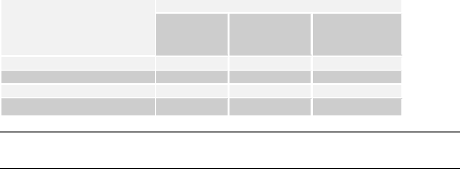
AirTight Management Console Configuration
21
The required authentication option can be activated based on the various combinations of the Enable
certificate based authentication box, Allow access without certificate box, and Users must provide
password along with certificate box.
The following table describes the activation of the authentication options based on the check boxes
selected by the user.
Authentication option to activate
Check box to be selected
Enable certificate
based
authentication
Allow access without
certificate
Users must provide
password along with
certificate
Password only
No
-
-
Certificate only
Yes
No
No
Certificate and password
Yes
No
Yes
Certificate or password
Yes
Yes
No
Note: In order to use certificate based authentication, it is necessary that the GUI host is able to access
the server at TCP port 4433. If there is a firewall between the GUI host and the server, port 4433 must be
opened from the host to the server.
When either Certificate only, Certificate and Password, or Certificate or Password option is activated, the
additional details should be provided as follows
• The field in the client certificate from which user identity can be retrieved by AirTight
Management Console.
• Root CA certificates to facilitate the verification of the client certificate.
• Preferred method to check for certificate revocation.
Restore Certificate Configuration Defaults
By default, certificate-based authentication is disabled.
To restore this default value, do the following.
1. Go to Configuration>User Accounts>Certificate Configuration.
2. Click Restore Defaults.
3. Click Save to save the changes.
Copy Certificate Configuration to Another Server
You can copy the Certificate configuration from one server to another server when both servers are part
of the same server cluster. You can copy Certificate configuration from child server to child server, parent
server to child server, or child server to parent server. You must be a superuser or an administrator to
copy policies from one server to another.
To copy Certificate configuration, do the following.
1. Go to Configuration>User Accounts>Certificate Configuration on the parent server.
2. Click Copy Policy. The Copy Policies dialog box appears.
3. Select the server from which the certificate configuration is to be copied.
4. Select the server to which the certificate configuration is to be copied.
5. Click OK to copy the certificate configuration,
AirTight Management Console User Guide
22
Wireless Intrusion Prevention System
A Wi-Fi network is easy to set up by way of access points. Small plug-and-play devices can act as access
points. Smart phones and tablets that are now widely used, are also Wi-Fi enabled. They can act as
mobile hotspots. Wireless clients can connect to any such access points and easily access a network that
is not adequately protected against such wireless threats. Thus, a network can become vulnerable to
wireless attacks. It is therefore important to understand and control the authorized and unauthorized
access to networks.
A proper wireless intrusion prevention (WIPS) policy needs to be in place to prevent unauthorized access
to a network. The rules for wireless intrusion prevention into the network can be configured using
Configuration>WIPS.
You can set the rules for WIPS using the options seen under Configuration>WIPS.
AirTight Management Console provides you the flexibility to set a generic WIPS policy for all locations in
the organization, or a location-wise WIPS policy for individual locations. You can have WIPS activated at
some locations and deactivated at others.
Make sure that you have defined your location tree before you can proceed with WIPS configuration.
You must have administrator privileges to do the WIPS settings.
Specify the authorized WLAN policy templates to identify authorized APs, using
Configuration>WIPS>Authorized WLAN Policy. This is inherited, by default, from the parent location. It
can also be customized for a location.
Configure the policy to auto-classify the APs detected by AirTight WIPS, using Configuration>WIPS>AP
auto-classification. This is inherited, by default, from the parent location. It can also be customized for a
location.
Configure the policy to auto-classify clients detected by AirTight WIPS, using
Configuration>WIPS>Client auto-classification. This is inherited, by default, from the parent location. It
can also be customized for a location.
Define the intrusion prevention policy, using Configuration>WIPS>Intrusion Prevention. This is
inherited, by default, from the parent location. It can also be customized for a location.
Activate or deactivate intrusion prevention for the selected location, using
Configuration>WIPS>Intrusion Prevention Activation. This is location specific. You need to first select
the desired location from the location tree. Then you use the Intrusion Prevention Activation option to
activate or deactivate intrusion prevention for this location.
Import device lists that can be referred to for AP/Client classification, using Configuration>WIPS>Import
Devices. This is location specific. You need to first select the desired location from the location tree. Then
you use the Import Devices option to import devices for this location.
You can manage banned device list with the Configuration>WIPS>Banned Device List option.
You can manage hotspot SSID list with the Configuration>WIPS>Hotspot SSIDs option.
You can manage hotspot SSID list with the Configuration>WIPS>Vulnerable SSIDs option.
You can manage the smart device types used in smart device detection with the
Configuration>WIPS>Smart Device Types option.
You can lock the list of authorized AP and/or clients for a location using the
Configuration>WIPS>Device List Locking option.

AirTight Management Console Configuration
23
Manage Authorized WLAN Policy
Specify the Authorized WLAN policy templates for the selected location in the location hierarchy using
Configuration>WIPS>Authorized WLAN Policy.
Authorized WLAN policy for a location includes a set of one or more policy templates that define the
properties of one or more authorized wireless networks. A policy template is a collection of different
network related settings such as wireless network protocols, encryption protocol used, allowed network
SSIDs, security settings, authentication type used, allowed networks and so on. An authorized WLAN
policy also specifies what networks are restricted from having Wi-Fi APs on them. Apart from this, you
can also specify what APs to categorize as rogue or authorized APs based on their RSSI signal strength.
All these parameters together constitute an authorized WLAN policy.
The RSSI of a device is statistical parameter. Using the RSSI feature can cause legitimate neighborhood
APs to be classified as Rogues and subjected to containment if automatic prevention is enabled. This will
cause neighbor Wi-Fi disruption since clients, including the legitimate neighborhood clients, will NOT be
able to connect to the Rogue AP under containment.
Even if the intention is to use RSSI to identify APs that are within the facility, it will not always work since
low power APs such as soft APs, hotspot APs running on smart phones, USB APs, etc. or APs which are
away from RSSI measurement point will still not get classified as Rogue APs due to not meeting the RSSI
threshold.
Policy templates aid in the classification of APs. A new AP or an existing Authorized AP is compared
against the templates to determine if it is a rogue or misconfigured AP. Any AP at a location that does not
comply with the WLAN policy attached to that location, is not considered to be an authorized AP.
You must apply the templates from the available list for the WLAN policy at that location.
Authorized policy templates are used to identify authorized APs and constantly check that the actual Wi-
Fi access parameters provisioned on the authorized APs meet the security policy. You can define multiple
WLAN policy templates and assign them to each location. Any new AP that is added to a location is
verified on the basis of the WLAN policy templates attached to that location. Any mismatch is used to
detect misconfiguration of the Wi-Fi access network.
The system uses the details of the authorized Wi-Fi setup at a particular location to detect the presence
of misconfigured or rogue APs in your network.
An AP is considered as being compliant to the Authorized WLAN Policy if:
• It is not connected to a No Wi-Fi network for its location
• Its SSID matches with one of the templates attached at that location
• Is connected to one of the networks specified in that template
• Conforms to the other settings in that template (except the Authentication Framework, as this setting
is not a property of the AP itself but of the backend authentication system).
Note: If the template specifies certain allowed AP capabilities (such as Turbo, 802.11n, and so on), the
AP may or may not have those capabilities. However, if a capability is not selected, the AP must not have
that capability to be considered as compliant.
With location-based policies, you can apply different sets of policy templates for different locations.
However, you cannot attach more than one template with the same SSID at any one location.
Only the policy templates that are applied to a location are used for AP classification at that location.
Other templates that are configured but not applied to the location, will not be used for AP classification,
as they are not a part of the WLAN policy for that location.

AirTight Management Console User Guide
24
The authorized policy templates created at other locations can be applied to a selected location but
cannot be edited or deleted. The edit and delete operations are possible only at the location where the
template is created.
A child location automatically inherits the authorized WLAN policy from its parent. You can customize the
WLAN policy for a child location. You can also switch back to an inherited policy in case you have created
a customized policy.
Configure Authorized WLAN Policy
To configure an authorized WLAN policy for a location, do the following.
1. Select the location from the location tree.
2. Go to Configuration>WIPS>Authorized WLAN Policy.
3. If Wi-Fi has been deployed at the location, select the Wi-Fi is deployed at this location check box.
The Policy Template and Select "No Wi-Fi" Networks sections on this page are enabled on
selecting this check box.
4. If you want to use an existing policy template, click the Applied icon for the existing policy template to
be applied to the location. Alternatively, Click Add New Policy Template if no policy template exists,
and add a new policy template. Refer to the Add Device Template or Edit Device Template
subsection in the Manage Policy Templates section for details on how to add or edit a policy
template.
5. If there are any networks at the location that are not allowed to have APs connected to them,
a) Scroll down to the Select "No Wi-Fi" Networks section
b) Click Add. The Add Networks dialog box appears.
c) Enter the SSID or IP address of the network to add.
6. Define RSSI based classification, if the WIPS is intended for use in an isolated environment without
much of a neighborhood activity like defense and military facilities. It is recommended to skip this
section altogether in case of commercial or business district environments. Either of the following two
mechanisms must be switched on to classify the APs.
a) Enter the threshold RSSI value to use for preclassification of APs with signal strength stronger
than this value as rogue or unauthorized APs.
b)Select the Preclassify APs connected to monitored subnets as Rogue or Authorized APs to
preclassify the APs connected to monitored subnets as rogue or authorized APs.
7. Click Save to save the changes.
Edit Authorized WLAN Policy
To edit an authorized WLAN policy for a location, do the following.
1. Select the location from the location tree.
1 Go to Configuration>WIPS>Authorized WLAN Policy.
2. If you want to apply an existing policy, click the Applied icon for that policy in the policy template list.
3. If you want to make changes to the policy template, click the policy template link in the policy
template list. If you want to add a new policy template click Add New Policy Template, and add a
new policy template. Refer to the Add Device Template or Edit Device Template subsections in the
Manage Policy Templates section for details on how to add or edit a policy template.
4. If there are any networks at the location that are not allowed to have APs connected to them,
a) Scroll down to the Select "No Wi-Fi" Networks section
b) Click Add. The Add Networks dialog box appears.
c) Enter the SSID or IP address of the network to add.
5. Define RSSI based classification, if the WIPS is intended for use in an isolated environment without
much of a neighborhood activity like defense and military facilities. It is recommended to skip this
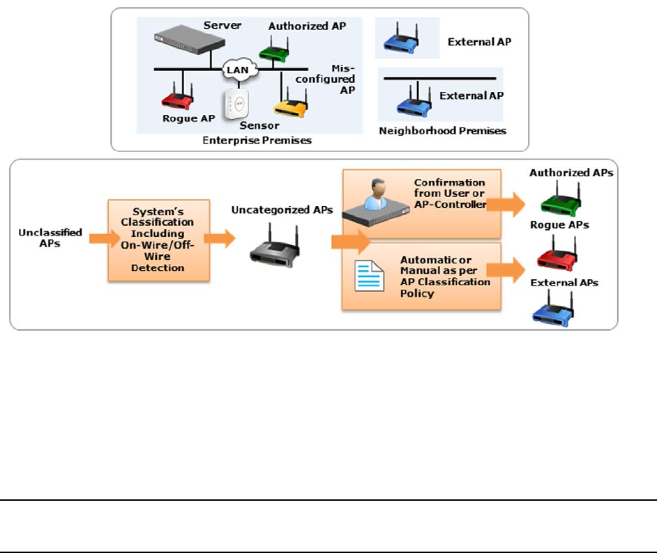
AirTight Management Console Configuration
25
section altogether in case of commercial or business district environments. Either of the following two
mechanisms must be switched on to classify the APs.
a) Enter the threshold RSSI value to use for preclassification of APs with signal strength stronger
than this value as rogue or unauthorized APs.
b)Select the Preclassify APs connected to monitored subnets as Rogue or Authorized APs to
preclassify the APs connected to monitored subnets as rogue or authorized APs.
6. Click Save to save the changes.
Configure AP Auto-classification Policy
The AP Auto-Classification policy function enables you to specify the AP classification policy for different
AP categories.
It is important to know about the authenticity of APs in the network as unauthorized APs can cause
irreparable damage to your network and business.
AP classification is of prime importance in WIPS implementation.
A diagrammatic representation of AP classification is shown below.
AP classification
Under External APs, AirTight recommends that you select Automatically move Potentially External APs in
the Uncategorized list to the External Folder. The system automatically removes an AP from the External
folder and moves it to an appropriate AP folder if it later detects that the AP is wired to the enterprise
network.
Under Rogue APs, AirTight recommends that you select Automatically move Potentially External APs in
the Uncategorized list to the Rogue folder.
Note: Once you move an AP to the Rogue folder, the system never automatically removes it from the
Rogue folder, even if it later detects that the AP is unwired from the enterprise network or its security
settings have changed.
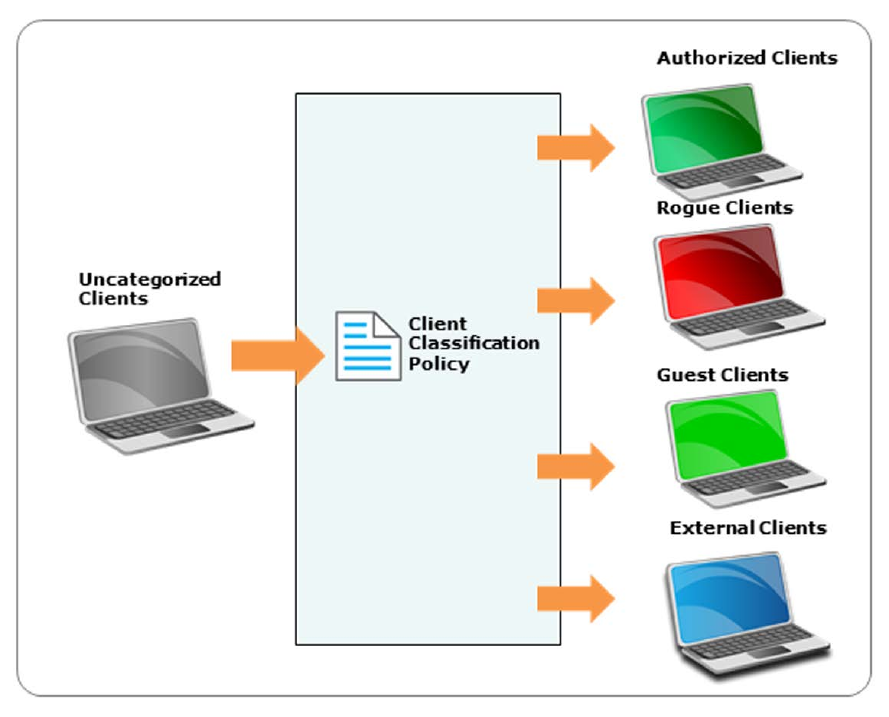
AirTight Management Console User Guide
26
Configure Client Auto-classification Policy
The client auto-classification policy determines how clients are classified upon initial discovery and
subsequent associations with APs.
Client auto classification
Define how the system should automatically classify the detected wireless clients at the selected location
based on their initial discovery and subsequent AP associations. This policy is automatically inherited by
child locations of the selected location. The intrusion prevention actions enforced on the wireless clients
are based on their classification in the system.
If a client is ever manually classified, then it is never automatically classified by the system until it is
deleted from the system and rediscovered.
Under Initial Classification, select the Automatically classify newly discovered Clients at this
location as check box and specify if newly discovered clients at a particular location, which are
Uncategorized by default should be classified as External, Authorized or Guest.
Under Automatic Client Classification, select one or more options to enable the system automatically re-
classify Uncategorized and Unauthorized Clients based on their associations with APs. You can
categorize the following types of clients.
• Clients running AirTight Mobile
• All External Clients running AirTight Mobile are classified as Authorized
• All Uncategorized Clients running AirTight Mobile are classified as Authorized
• All Rogue Clients running AirTight Mobile are classified as Authorized
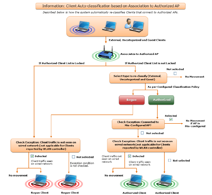
AirTight Management Console Configuration
27
• All Guest Clients running AirTight Mobile are classified as Authorized
• Clients connecting to Authorized APs
• All External Clients that connect to an Authorized AP are re-classified as Authorized
• All Uncategorized Clients that connect to an Authorized AP are reclassified as Authorized
• All Guest Clients that connect to an Authorized AP are reclassified as Authorized
You can select the following exceptions.
• Do not reclassify a Client connecting to a Misconfigured AP as Authorized
• Do not reclassify a Client if its wireless data packets are not detected on the wired network
(except if the connection is reported by WLAN controller).
Classification for clients connecting to Authorized APs
Click Advanced to configure the auto classification settings for clients connecting to guest APs and
external APs.
• Clients connecting to Guest APs
• All External Clients that connect to a Guest AP are reclassified as Guest
• All Uncategorized Clients that connect to a Guest AP are reclassified as Guest
You can select the following exceptions
• Do not re-classify a Client connecting to a Mis-configured AP as Guest
• Do not re-classify a Client as Guest if its wireless data packets are not detected on the wired
network (except if the connection is reported by WLAN controller)
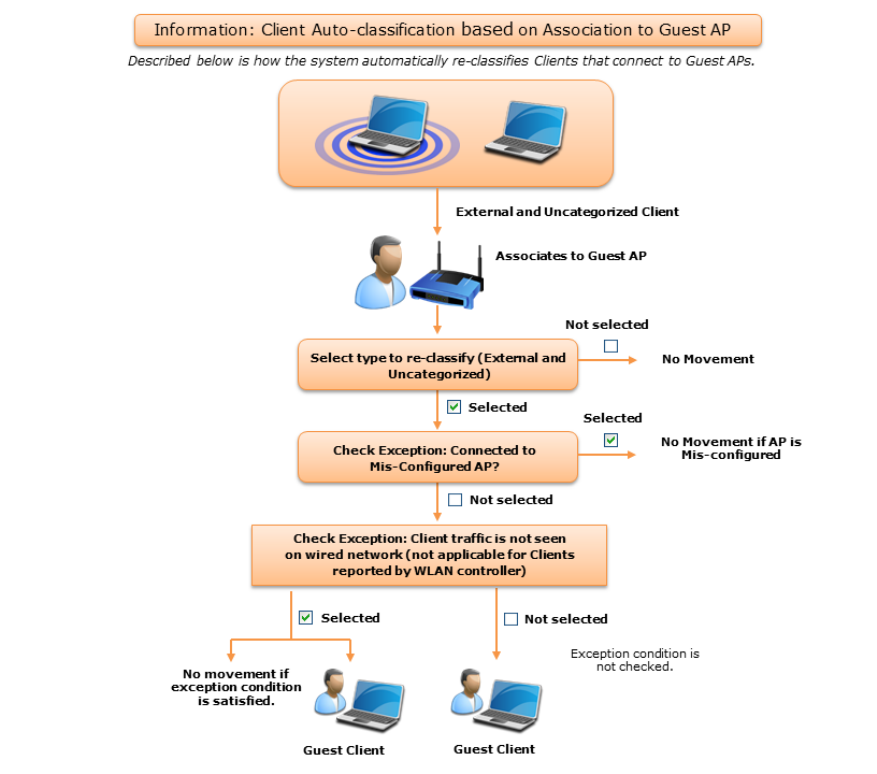
AirTight Management Console User Guide
28
Classification for Clients connecting to Guest APs
• Clients connecting to External APs
• All Uncategorized Clients that connect to an External AP are reclassified as External
• All Uncategorized Clients that connect to a Potentially External AP are classified as External
• All Guest Clients that connect to an External AP are re-classified as External
• All Guest Clients that connect to a Potentially External AP are re-classified as External
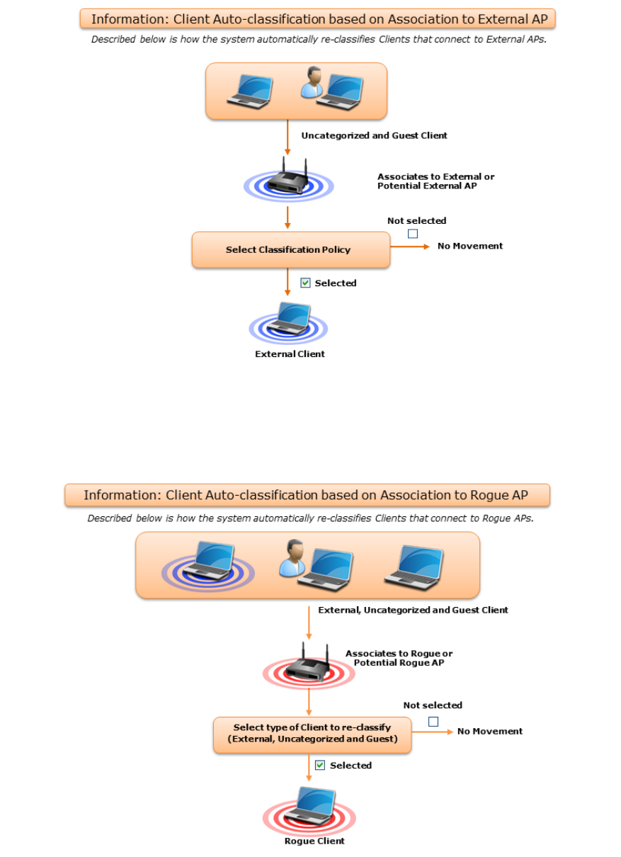
AirTight Management Console Configuration
29
Classification of Clients connecting to External APs
• Clients connecting to Rogue APs
• All Clients other than Authorized Clients that connect to a Rogue AP are (re)classified as
Rogue
• All Clients other than Authorized Clients that connect to a Potentially Rogue AP are classified
as Rogue
Classsification of Clients connecting to Rogue APs
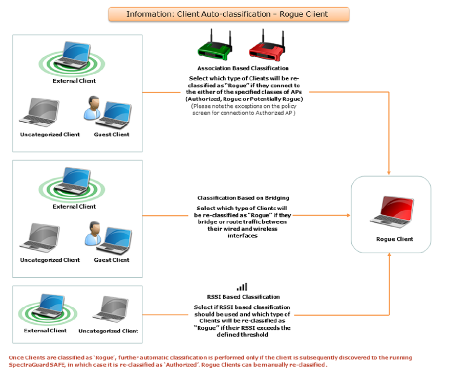
AirTight Management Console User Guide
30
• Bridging to the Corporate Network
• Classify any non-authorized Client as Rogue if it is detected as bridging Wi-Fi to the corporate
network
• RSSI Based Classification
You can enable RSSI based client classification for uncategorized clients and/or external clients
and configure RSSI based classification for them. Specify a RSSI threshold and the category for
such clients.
Classification of Clients bridging to corporate network and RSSI based classification
Intrusion Prevention
The Intrusion Prevention Policy determines the wireless threats against which the system protects the
network automatically. The system automatically moves such threat-posing APs and Clients to
quarantine. The system can protect against multiple threats simultaneously based on the selected
Intrusion Prevention level.
If the server quarantines an AP or Client based on the Intrusion Prevention policy, the Disable Auto-
quarantine option ensures that the system will not automatically quarantine this AP or Client (regardless
of the specified Intrusion Prevention policies).
AirTight Management Console can prevent any unwanted communication in your 802.11 network. It
provides you various levels of prevention-blocking mechanisms of varying effectiveness. Intrusion
AirTight Management Console Configuration
31
Prevention Level enables you to specify a trade-off between the desired level of prevention and the
desired number of multiple simultaneous preventions across radio channels.
The greater the number of channels across which simultaneous prevention is desired, the lesser is the
effectiveness of prevention in inhibiting unwanted communication. Scanning for new devices continues
regardless of the chosen prevention level.
You can select from the following intrusion prevention levels:
• Block: A single sensor can block unwanted communication on any one channel in the 802.11b/g band
and any one channel in the 802.11a band.
• Disrupt: A single sensor can disrupt unwanted communication on any two channels in the 802.11b/g
band and any two channels in the 802.11a band.
• Interrupt: A single sensor can interrupt unwanted communication on any three channels in the
802.11b/g band and any three channels in the 802.11a band.
• Degrade: A single sensor can degrade the performance of unwanted communication on any four
channels in 802.11b/g band and any four channels in the 802.11a band.
Block is the most powerful prevention level, that is, it can severely block almost all popular Internet
applications including ping, SSH, Telnet, FTP, HTTP, and the like. However, at this level, a single sensor
can simultaneously prevent unwanted communication on only one channel in the 802.11b/g band and
one channel in the 802.11a band. If you want the sensor to prevent unwanted communication on multiple
channels simultaneously in the 802.11 b/g and/or the 802.11a band, you must select other prevention
levels.
Note: Prevention Type determines the blocking strength to prevent communication from unwanted APs
and Clients. The system can prevent multiple APs and Clients on each channel. Prevention Type is not
applicable for Denial of Service (DoS) attacks or ad hoc networks. You must select a lower blocking level
to prevent devices on more channels. Choosing a lower blocking level means that some packets from the
blocked device may go through.
You can enable intrusion prevention against the following threats
• Rogue APs: APs connected to your network but not authorized by the administrator; an attacker can
gain access to your network through the Rogue APs. You can also automatically quarantine
uncategorized, indeterminate and banned APs connected to the network.
• Misconfigured APs: APs authorized by the administrator but do not conform to the security policy; an
attacker can gain access to your network through misconfigured APs. This could happen if the APs
are reset, tampered with, or if there is a change in the security policy.
• Client Misassociations: Authorized Clients that connect to rogue or external (neighboring) APs;
corporate data on the authorized client is under threat due to such connections. AirTight recommends
that you provide automatic intrusion prevention against authorized clients that connect to rogue or
external APs.
There is a special intrusion prevention policy for the smart devices that are not approved. Even if a
current client policy restricts authorized clients from connecting to a guest AP, an unapproved smart
device can still be allowed to do so. One needs to explicitly allow or restrict unapproved smart devices
from connecting to a guest AP.
Click Special Handling for Smart Devices to enable special handling for unapproved smart devices.
You can allow the unapproved smart device to connect to a guest AP only. To do this,
1. Select Enable Special Handling for Unapproved Smart Devices.
2. Select Allow connection to Guest AP, but not Authorized AP.
To disallow the unapproved smart device from connecting to both a guest AP as well as an authorized
AP, select Do not allow connection to Guest AP and Authorized AP.
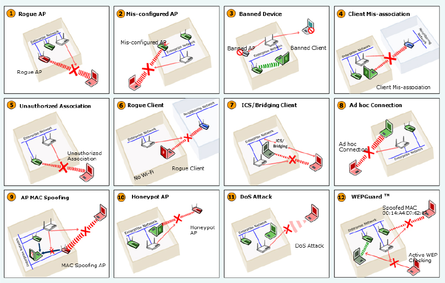
AirTight Management Console User Guide
32
Wireless Threats
Following is a diagrammatic representation of the various wireless threats.
Wireless Threats
Non-authorized Associations: Non-authorized and Banned Clients that connect to Authorized APs; an
attacker can gain access to your network through Authorized APs if the security mechanisms are weak.
Non-authorized or Uncategorized Client connections to an Authorized AP using a Guest SSID are not
treated as unauthorized associations.
• Associations to Guest APs: External and Uncategorized Clients that connect to Guest APs are
classified as Guest Clients. The Clients connected to a wired network or a MisConfigured AP can be
specified as exceptions to this policy.
• Ad hoc Connections: Peer-to-peer connections between Clients; corporate data on the Authorized
Client is under threat if it is involved in an ad hoc connection.
• MAC Spoofing: An AP that spoofs the wireless MAC address of an Authorized AP; an attacker can
launch an attack through a MAC spoofing AP.
• Honeypot/Evil Twin APs: Neighboring APs that have the same SSID as an Authorized AP; Authorized
Clients can connect to Honeypot/Evil Twin APs. Corporate data on these Authorized Clients is under
threat due to such connections.
• Denial of Service (DoS) Attacks: DoS attacks degrade the performance of an official WLAN.
• WEPGuard TM: Active WEP cracking tools allow attackers to crack the WEP key and gain access to
confidential data in a matter of minutes or even seconds. Compromised WEP keys are used to gain
entry into the authorized WLAN by spoofing the MAC address of an inactive Authorized Client.
• Client Bridging/ICS: A Client with packet forwarding enabled between wired and wireless interfaces. An
authorized Client bridging and unauthorized/uncategorized bridging Client connected to enterprise
subnet is a serious security threat.
Activate Intrusion Prevention for Location
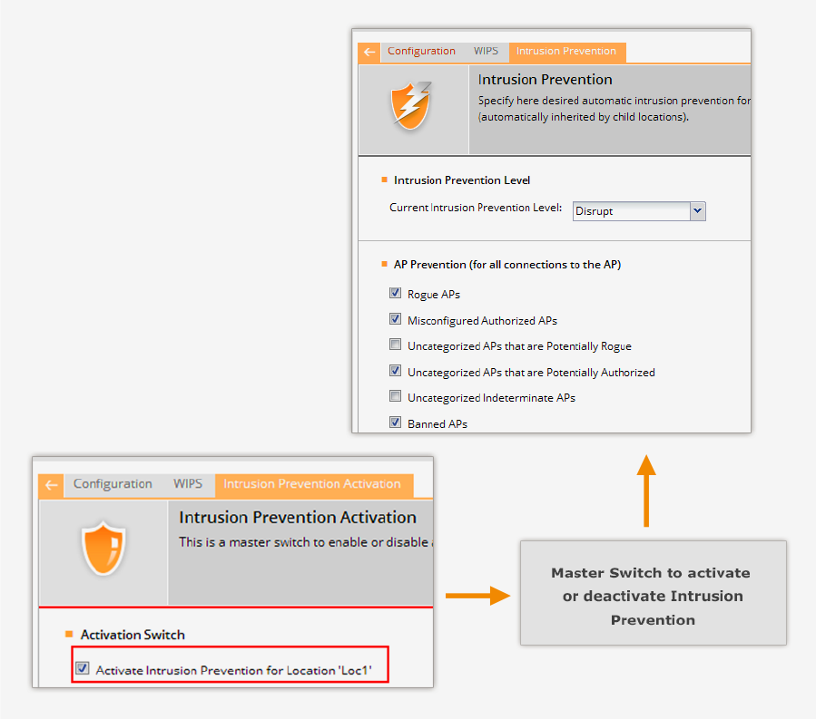
AirTight Management Console Configuration
33
Activate intrusion prevention for a location using the Configuration>WIPS>Intrusion Prevention
Activation option. The following figure explains intrusion prevention activation.
Intrusion Prevention Activation
The intrusion prevention policy is a location specific policy - it cannot be inherited from the parent
location.
Authorized APs should be in the Authorized folder before activating intrusion prevention. Their network
connectivity icon may show the status as Wired, Unwired, or Indeterminate.
If you deploy new Authorized APs later, you do not have to deactivate intrusion prevention. However, you
need to ensure that the newly deployed APs are moved to the Authorized folder.
AirTight recommends that you select the Activate Intrusion Prevention for <location> check box for
the selected location only after the deployment is stable and fully configured. If you are modifying a
deployment, clear the Activate Intrusion Prevention for <location> check box to avoid spurious activity
during the transient phase.
Click Save to the change. Click Cancel to cancel the change. Click Restore Defaults to restore the
default value.
Import Device List
AirTight Management Console User Guide
34
Importing an authorized AP List and an authorized or unauthorized client list is an efficient alternative to
manual movement of these devices into the authorized / unauthorized bins. After successfully importing
these lists, the system automatically classifies the APs and Clients in the respective lists as authorized or
unauthorized.
This is a location specific property and cannot be inherited from the parent location folder. You need
administrator rights to import a device list.
You can import authorized AP list, authorized client list, guest client list, rogue client list, and AirTight
device list into AirTight Management Console using the Configuration>WIPS>Import Devices option.
Format of the .txt or.csv file containing the AP/Client data
Each line has comma separated list of MAC Address, IP Address, Device Name. For example,
11:11:11:11:11:11,192.168.8.1,name1
11:11:11:11:11:12,192.168.8.2,name2
11:11:11:11:11:13,192.168.8.3,name3
11:11:11:11:11:14,192.168.8.4,name4
11:11:11:11:11:15,192.168.8.5,name5
11:11:11:11:11:16,192.168.8.6,name6
11:11:11:11:11:17,192.168.8.7,name7
Format of.txt or .csv file containing the AirTight Device data
Each line has comma separated list of MAC Address, Device Name. For example,
44:77:11:22:44:77, name1
44:77:11:22:11:12, name2
44:77:11:22:11:13, name3
44:77:11:22:11:14, name4
44:77:11:22:11:15, name5
Points to remember
• Once you move an AP to the Authorized folder, AirTight Management Console never removes it from
the Authorized folder automatically, even if the AP is unwired from the enterprise network.
• When you import APs from the list, policy settings in the Setup Wizard do not affect these APs.
• When you import sensors from the list, you can delete these sensors only from the Devices page.
• When you import clients from the list, policy settings in the Setup Wizard do not affect these clients.
To import devices, do the following.
1. Select the appropriate option from the Import list box, depending on whether you want to import an
authorized AP list, an authorized client list, a guest client list, a rogue client list, or a sensor list. The
text on the command button below the device list changes based on your selection. For instance, if
you select the option Import Authorized Client List from the list box, the text on the command
button changes to Import Authorized Client List.
2. Under the Auto Tag Devices area, select Auto tag Devices to automatically tag the device(s) to the
selected location. Select Manually Tag Devices to, to manually tag the device(s) to the selected
location.
3. Enter the MAC address, IP address and name of the AP or client. If the device is a sensor, enter the
MAC address and the name of the sensor. Alternatively, you can specify a filename containing the
AP/client/sensor data. Click Autofill using File, and select the .txt or .csv file containing the
AP/client/sensor data.
4. Click Import Authorized AP List to import the list of authorized APs. Click Import Authorized Client
List to import the list of authorized clients. Click Import Guest Client List to import the list of guest
AirTight Management Console Configuration
35
clients. Click Import Rogue Client List to import the lists of rogue clients. Click Import Sensor List
to import the list of sensors. The file has to be a text file or a csv file. Refer to the subsequent sections
for the text and csv file formats for the AP, client and sensor lists.
Once imported successfully, the devices are seen under their respective tabs on the Devices page. The
Dashboard page also reflects the activity of the newly imported sensors, APs, and clients.
Delete device details from device list
To delete the device details from the device list, do the following.
1. Select the AP/client/sensor row and click the corresponding Delete hyperlink.
2. Click Yes when asked to confirm deletion.
Manage Banned Device List
You can create and manage a list of banned APs and banned clients using the
Configuration>WIPS>Banned Device List option. If the devices from this list are detected, they are not
classified as rogue devices.
Create banned AP list
You can add the wireless MAC addresses of APs that are blacklisted in your organization. If APs with
these MAC addresses become visible, AirTight Management Console generates an alert.
You can either enter individual AP MAC addresses or to import a list of banned APs in to the database.
To add an individual AP MAC address, do the following.
1. Go to Configuration>WIPS>Banned Device List.
2. Click to expand Banned AP List.
3. Click Add MAC Address. The Add to Banned List dialog box appears.
4. Click Add MAC Address under Banned AP list and enter the MAC Address of a banned AP. You can
add one or more banned AP MAC addresses in this manner.
You can also import a list of AP MAC addresses from a file. The file containing the list of AP MAC
addresses must be a CSV file.
To import a file containing a list of AP MAC addresses, do the following.
1. Go to Configuration>WIPS>Banned Device List
2. Click to expand Banned AP List.
3. Click Add MAC Address. The Add to Banned List dialog box appears.
4. Click File Upload.
5. Click Choose File to choose the file and then click Upload to upload the selected file.
6. Click Add to add the imported AP MAC addresses to the banned device list.
Create banned Client list
You define the wireless MAC addresses of Clients that are blacklisted in your organization. For example,
such MAC addresses could belong to laptops of employees who are no longer with the organization. If
APs with these MAC addresses become visible, AirTight Management Console generates an alert.
AirTight Management Console User Guide
36
You can either enter individual client MAC addresses or to import a list of banned clients to the database.
To add an individual client MAC address, do the following.
1. Go to Configuration>WIPS>Banned Device List.
2. Click to expand Banned Client List.
3. Click Add MAC Address. The Add to Banned List dialog box appears.
4. Click Add Device link to add a MAC address manually.
5. Enter the MAC address to add. You can add one or more banned client MAC addresses in this
manner.
6. Click Add to add the devices to the banned device list.
You can also import a list of client MAC addresses. The file containing the list of client MAC addresses
must be a CSV file.
To import a file containing a list of client MAC addresses, do the following.
1. Go to Configuration>WIPS>Banned Device List.
2. Click to expand Banned Client List.
3. Click Add MAC Address. The Add to Banned List dialog box appears.
4. Click File Upload.
5. Click Choose File to choose the file and then click Upload to upload the selected file.
6. Click Add to add the imported client MAC addresses to the banned device list.
Delete Banned Device
1. Go to Configuration>WIPS>Banned Device List.
2. Click the Delete link for the device to be deleted. A confirmation message is displayed to confirm
deletion.
3. Click Yes to confirm deletion
Copy Banned Device List to Another Server
You can copy the banned device list from one server to another server when both servers are part of the
same server cluster. You can copy banned device list from child server to child server, parent server to
child server, or child server to parent server. You must be a superuser or an administrator to copy policies
from one server to another.
To copy banned device list, do the following.
1. Go to Configuration>WIPS>Banned Device List on the parent server.
2. Click Copy Policy. The Copy Policies dialog box appears.
3. Select the server from which the banned device list is to be copied.
4. Select the server to which the banned device list to be copied.
5. Click OK to copy the banned device list,
Manage Hotspot SSIDs
Configure and manage a list of hotspot SSIDs using the Configuration->WIPS-> Advanced Settings-
>Hotspot SSIDs option.
It is highly likely that hotspot APs are present in the enterprise neighborhood. If enterprise Client probes
for well known hotspot SSID, it is at risk of connecting to the hotspot AP without the user necessarily
knowing about it. Also if enterprise AP uses hotspot SSID on it, such an AP may attract undesirable
Clients to connect to it.
AirTight Management Console Configuration
37
If you consider an SSID to be vulnerable to hackers, you can open the Hotspot SSIDs screen and enter
the SSID under SSID (ASCII character string).
Add Hotspot SSIDs
The system lists commonly known SSIDs by default. To enter a blank SSID: that is, with no string, click
<Add> without entering any text. The list shows the SSID as NULL.
To add a hotpsot SSID, do the following.
1. Go to Configuration>WIPS>Advanced Settings>Hotspot SSID.
2. Click Add New Hotspot SSID. The Add New Hotspot SSID dialog box appears.
3. Enter a new hotspot SSID and click OK. If an AP with a hotspot SSID is detected, the system
generates an event.
Search Hotspot SSIDs
To search for hotspot IDs, do the following.
1. Go to Configuration>WIPS>Advanced Settings>Hotspot SSID.
2. Type in the search string in the search SSID box and press the Enter key. A list of hotspot SSIDs
matching the search criteria appears.
To clear the search string, click the x icon next to the search SSID box.
Delete Hotspot SSID
To delete hotspot SSIDs, do the following.
1. Go to Configuration>WIPS>Advanced Settings>Hotspot SSID.
2. click Delete link for the SSID to be deleted.
3. Click Yes on the confirmation message to confirm the deletion of the hotspot SSID.
Restore Default Hotspot SSID list
To restore the default hotspot SSID list, do the following.
1. Go to Configuration>WIPS>Advanced Settings>Hotspot SSIDs
2. Click Restore Defaults. A confirmation message prompting you to confirm the operation appears.
3. Click Yes. The default hotspot SSID list is restored.
Copy Hotspot SSID List to Another Server
You can copy the list of hotspot SSIDs from one server to another server when both servers are part of
the same server cluster. You can copy a list of hotspot SSIDs from child server to child server, parent
server to child server, or child server to parent server. You must be a superuser or an administrator to
copy policies from one server to another.
To copy a list of hotspot SSIDs, do the following.
1. Go to Configuration>WIPS>Advanced Settings>Hotspot SSIDs on the parent server.
2. Click Copy Policy. The Copy Policies dialog box appears.
3. Select the server from which the list of hotspot SSIDs is to be copied.
AirTight Management Console User Guide
38
4. Select the server to which the list of hotspot SSIDs is to be copied.
5. Click OK to copy the list of hotspot SSIDs.
Manage Vulnerable SSIDs
Configure and manage a list of vulnerable SSIDs using the Configuration>WIPS>Advanced
Settings>Vulnerable SSIDs option.
APs have well known default SSIDs and many users may not change these SSIDs when deploying the
APs. Therefore it is highly likely that APs using default SSIDs are present in the enterprise neighborhood.
If an enterprise Client probes for a default SSID, it is at risk of connecting to the neighborhood AP without
the user necessarily knowing about it. Also if an enterprise AP uses a default SSID, such an AP may
attract undesirable clients to connect to it.
Add Vulnerable SSID
If you consider an SSID to be vulnerable to hackers, you can add the SSID to the Vulnerable SSIDs list.
To add a vulnerable SSID, do the following.
1. Go to Configuration>WIPS>Advanced Settings>Vulnerable SSIDs.
2. Click Add New Vulnerable SSID.
3. Enter the SSID and click OK to add it to the list of vulnerable SSIDs. If an AP point with a vulnerable
SSID is detected, the system generates an event.
Note: Commonly known SSIDs are listed by default. To enter a blank SSID: no string, click Add without
entering any text. The list shows the SSID as NULL.
Search Vulnerable SSID
To search a vulnerable SSID, do the following.
1. Go to Configuration->WIPS-> Advanced Settings->Vulnerable SSIDs
2. Type in the search string in the search SSID box and press the Enter key. A list of vulnerable SSIDs
matching the search criteria is displayed.
To clear the search string, click the x icon next to the search SSID box.
Delete Vulnerable SSID
To delete a vulnerable SSID, do the following.
1. Go to Configuration->WIPS-> Advanced Settings->Vulnerable SSIDs
2. Click Delete link for the SSID to be deleted.
3. Click Yes on the confirmation message to confirm the deletion of the vulnerable SSID.
Restore Default Vulnerable SSID list
To restore the default vulnerable SSID list, do the following.
1. Go to Configuration>WIPS>Advanced Settings>Vulnerable SSIDs
2. Click Restore Defaults. A confirmation message prompting you to confirm the operation appears.
AirTight Management Console Configuration
39
3. Click Yes. The default vulnerable SSID list is restored.
Copy Vulnerable SSID List to Another Server
You can copy the list of vulnerable SSIDs from one server to another server when both servers are part of
the same server cluster. You can copy a list of vulnerable SSIDs from child server to child server, parent
server to child server, or child server to parent server.
You must be a superuser or an administrator to copy policies from one server to another.
To copy a list of vulnerable SSIDs, do the following.
1. Go to Configuration>WIPS>Advanced Settings>Vulnerable SSIDs on the parent server.
2. Click Copy Policy. The Copy Policies dialog box appears.
3. Select the server from which the list of vulnerable SSIDs is to be copied.
4. Select the server to which the list of vulnerable SSIDs is to be copied.
5. Click OK to copy the list of vulnerable SSIDs.
Manage Smart Device Types
You can view, add, and delete the smart device types using the Configuration->WIPS-> Advanced
Settings->Smart Device Type option.
The Smart Device Type page shows the system-defined smart device types, and the user-defined smart
device types, if any.
Add Smart Device Type
You can add to the list of predefined smart device types.
To add a new smart device type, do the following.
1. Go to Configuration>WIPS>Advanced Settings>Smart Device Type.
2. Click Add new smart device type. The Add new smart device type dialog box appears.
3. Enter the Smart Device Type.
4. Click OK to add the smart device type to the existing list of smart device types.
Delete Smart Device Type
You can delete only the smart device types that have been manually added. You cannot delete the
system-defined smart device types.
To delete a user-defined smart device type, do the following.
1. Go to Configuration>WIPS>Advanced Settings>Smart Device Type
2. Select the smart device type and click Delete. A message appears prompting you to confirm the
deletion.
3. Click Yes to confirm the deletion.
Copy Smart Device Types List to Another Server
You can copy the list of smart device types from one server to another server when both servers are part
of the same server cluster. You can copy a list of smart device types from child server to child server,
AirTight Management Console User Guide
40
parent server to child server, or child server to parent server. You must be a superuser or an
administrator to copy policies from one server to another.
To copy a list of smart device types, do the following.
1. Go to Configuration>WIPS>Advanced Settings>Smart Device Type on the parent server.
2. Click Copy Policy. The Copy Policies dialog box appears.
3. Select the server from which the list of smart device types is to be copied.
4. Select the server to which the list of smart device types is to be copied.
5. Click OK to copy the list of smart device types.
AirTight Management Console Configuration
41
Manage WiFi Access
Wi-Fi profiles are used to define the Wi-Fi configuration of an AirTight Device in access point (AP) mode.
Wi-Fi Profiles are applied onto a radio of a device. The radio and the device must support access point
configuration.
Wi-Fi Profiles can be created on any location.
Wi-Fi profile is a Wi-Fi network profile. The profile is a set of configuration parameters related to a
wireless or Wi-Fi network. It consists of security, network, captive portal, firewall, traffic shaping, QoS and
BYOD settings. A single Wi-Fi profile represents a VLAN. Multiple VLANs can be configured for a single
AP. Thus, you can have different VLANs to provide different services using a single AP.
Manage SSID Profiles
When an AirTight device is configured as an access point (AP), you can use the access point to provide
various services, in parallel. This means that you can divide a physical AP into multiple virtual APs. Each
virtual AP can provide a service independently, without interfering with the services provided by other
virtual APs on the same physical AP.
An AirTight device operating as an AP supports multiple VLANs created on the wired side.
A Wi-Fi Profile (or SSID profile) is a set of network properties that are configured on a virtual AP. One or
more Wi-Fi profiles could represent or map to a single VLAN.
Let us consider an example. You could have different VLANs configured on the wired side, of which one
is serving the general corporate network and ne is provisioning network access for guests. Using the
AirTight device that is configured to function as an AP, you can define 2 or more virtual APs mapping to
the properties of the VLANs on the wired side. The wireless clients wanting to connect to the corporate
network would use the Wi-Fi profile mapping to the corporate VLAN and the wireless clients wanting to
connect to the guest network would use the Wi-Fi profile mapping to the guest VLAN.
A virtual AP has the following features:
• Supports Open, WPA (TKIP), WPA2 (CCMP),WPA/WPA2 (TKIP+CCMP) or 802.1x security. Distinct
virtual APs can have different security modes.
• Can be used to provide distinct services that are independent of each other.
• Maps wireless traffic from virtual AP to a specific VLAN so that data transmitted and received by
wireless client will be seen on only the specified VLAN. It will not appear on other VLANs.
Starting with AirTight Management Console 7.1 U2, AirTight APs support Hotspot 2.0 Release 1.
Configuring the Hotspot 2.0 settings on an AirTight AP enables Passpoint-certified mobile devices to
seamlessly connect to the AirTight AP without the need for authentication.
Configure Wi-Fi Profiles using Configuration>Device Configuration>SSID Profiles.
Important: You cannot configure BYOD settings and captive portal settings on the same Wi-Fi profile.
Each should be configured on independent Wi-Fi profiles.
Add Wi-Fi Profile
You can add multiple Wi-Fi profiles for an AirTight device operating in the AP mode. When in AP mode, a
single physical AP device can be logically split up into multiple virtual APs. Each wireless profile
represents the configuration settings of a virtual AP. Multiple virtual APs can be configured on a single
radio. Up to 8 such virtual APs can be configured using the Add/Edit Wi-Fi Profiles dialog box.

AirTight Management Console User Guide
42
Each Wi-Fi profile has a set of WLAN settings. Configure the WLAN settings for an AP in the WLAN tab.
You can configure the following settings for a Wi-Fi profile.
• Security Settings: Security settings specify the type of security used by the AP to authenticate
wireless clients. For details on configuring security settings, refer to the Security Settings section.
• Network Settings: The VLAN and DHCP settings for the Wi-Fi profile are configured under network
settings. For details on configuring network settings, refer to the Network Settings section.
• Captive Portal Settings: To enable captive portal on the Wi-Fi profile for guest login, you must
configure the captive portal settings. These settings comprise splash page configuration, walled
garden settings, external portal parameters etc. For details on configuring captive portal settings,
refer to the Captive Portal Settings section.
• Firewall Settings: Firewall rules for the Wi-Fi profile are configured under the firewall settings. The
incoming and outgoing traffic through a virtual AP can be controlled by defining firewall rules. For
details on configuring the firewall rules, refer to the Firewall Settings section.
• SSID Scheduling Settings: If you want to limit the duration for which the SSID is active, you can
define a schedule for the SSID. You can also specify if an SSID is to be permanently active or valid
for only a limited time duration. For details on SSID scheduling, refer to the SSID Scheduling section.
• Traffic Shaping & QoS Settings: Effective utilization of network bandwidth can be achieved by
setting an upload and download limit for the network, restricting the number of client association,
band steering and defining QoS parameters. You can configure these settings under traffic shaping
and QoS settings. For details on configuring these settings, refer to the Traffic Shaping and QoS
Settings section.
• BYOD- Device Onboarding Settings: These settings govern whether the wireless clients can
connect to APs in a corporate network. For instance, if the employees get their own smart devices to
office, the SSID profile can be configured to allow or disallow such devices from connecting to the
corporate network. You can also restrict access for such devices with the device onboarding settings.
For details on configuring these settings, refer to BYOD-Device Onboarding section.
• Hotspot 2.0 Settings: If you want to deploy the AP in a Hotspot 2.0 operator's network such that the
AP functions as a Hotspot 2.0 AP, you must configure the Hotspot 2.0 settings as well. These are
configured in the Hotspot 2.0 tab. The Hotspot 2.0 settings are required only if you want to enable
hotspot 2.0 support on the AP; otherwise configuration of WLAN settings alone is sufficient. For
details, on configuring these settings, refer to the Hotspot 2.0 Settings section
You can choose to collect analytics data for reporting purpose about the client-AP association.
Association analytics and content analytics can be collected if you enable the collection of these analytics
in the Wi-Fi profile.
Association Analytics comprises the data related to the client - AP communication. The following data is
collected as association analytics.
• Client MAC address
• Protocol
• SSID of the network to which the client connects
• Location of the client
• Start time of client association with the AP (GMT)
• End time of client association with the AP (GMT)
• Start time of client association with the AP according to local time of the user
• End time of client association with the AP according to local time at the user
• Session duration
AirTight Management Console Configuration
43
• Data transfer from client device in bytes
• Data transfer to client device in bytes
• Data rate in Kbps
• Smart device type
• Local Time Zone
The following information is present for each internet domain as content analytics information.
• Domain name
• Data transferred to the domain (in bytes)
• Data received from the domain (in bytes)
To add a Wi-Fi profile, do the following.
1. Go to Configuration>Device Configuration>SSID Profiles.
2. Select the location for which the Wi-Fi profile is to be created.
3. Click Add New Wi-Fi Profile. The WLAN and Hotspot 2.0 tabs are displayed.
4. Enter the following details on the WLAN tab.
Field
Description
Profile
Name
Name of the Wi-Fi profile
SSID
SSID or network name of the Wi-Fi profile. This would be the SSID of
the wired network that the wireless user would connect to.
Broadcast
SSID
Enables or disables broadcast of SSID in the wireless packet.
Select the check box to broadcast the SSID with the wireless packets.
Leave it clear or deselect the check box if you do not want to
broadcast the SSID with the wireless packets.
Association
Analytics
Enables or disables association analytics in reports.
Select the check box to enable association analytics in reports.
Leave it clear or deselect the check box if you do not want association
analytics data in reports.
Content
Analytics
Enables or disables content analytics in reports. This check box is
visible only if you have selected the Association Analytics check box.
Content analytics capture information related to the Internet domains or
IP addresses accessed by the client associated with the AirTight APs.
Select the check box to collect internet domain access information as a
part of association analytics. This information is present in the CSV file
downloaded through Reports>Analytics.
Leave it clear or deselect the check box if you do not want content
analytics data in reports.
5. Fill in the other details based on how you want to configure the Wi-Fi profile. Refer to individual
sections on network settings, security settings, firewall settings, traffic shaping and QoS settings,
schedule SSID, captive portal settings, BYOD onboarding settings, Hotspot 2.0 Settings to configure the
respective settings.
6. Click Save to save and add the new Wi-Fi profile.
Replicate Wi-Fi Profile
If you have already created a Wi-Fi profile, you can create a similar Wi-Fi profile with minor changes.
To make a copy of an existing Wi-Fi profile with minor changes, do the following
1. Go to Configuration>Device Configuration>SSID Profiles.
2. Select the location.
3. Open the Wi-Fi profile to replicate.
4. Enter a new name for the Wi-Fi profile.
AirTight Management Console User Guide
44
5. Make the required changes to this profile.
6. Click Save As. A Wi-Fi profile is created with the new name.
Edit Wi-Fi Profile
The Wi-Fi profile can be edited only at the location where it has been created.
To edit a Wi-Fi profile, do the following
1. Go to Configuration>Device Configuration>SSID Profiles.
2. Select the location for which the Wi-Fi profile has been created.
3. Click the Wi-Fi profile name hyperlink to edit.
4. Make the required changes.
5. Click Save to save the changes to the Wi-Fi profile.
Copy Wi-Fi profile to another location
To make a copy of an existing Wi-Fi profile to another location, do the following.
1. Go to Configuration>Device Configuration>SSID Profiles.
2. Select the location for which the Wi-Fi profile has been created.
3. On the SSID Profile page, select the check box for the SSID profile to copy to another location.
4. Click the Copy to location icon. The Select Location dialog box appears.
5. Select the location to which the Wi-Fi profile is to be copied. A copy of the selected Wi-Fi profile is
created at the selected location.
Delete Wi-Fi Profile
You cannot delete a Wi-Fi profile, if it is used in a device template. You can delete a Wi-Fi profile at a
selected location, only if you have defined the Wi-Fi profile at that location.
To delete a Wi-Fi profile, do the following.
1. Go to Configuration>Device Configuration>SSID Profiles.
2. Select the location for which the Wi-Fi profile has been created.
3. Click the Delete icon for the Wi-Fi profile. A message to confirm deletion appears.
4. Click Yes to confirm the deletion of the Wi-Fi profile.
Print List of Wi-Fi Profiles for Location
You can print a list of Wi-Fi profiles that have been defined for a location.
To print a list of Wi-Fi profiles at a location, do the following.
1. Go to Configuration>Device Configuration>SSID Profiles.
2. Click the Wi-Fi Profiles tab.
3. Select the columns that you want in the printed list. Click any column name to select or deselect
columns.
4. Click the Print icon. A print preview of the list appears.
5. Click Print to print the list.
Security Settings
The security settings for a virtual AP could be either of the following:
• Open: Open means no security settings are to be applied. This is the default security setting.
• WEP: WEP stands for Wireless Equivalent Privacy. WEP is a deprecated security algorithm for
IEEE 802.11 networks. This has been provided for backward compatibility purpose only.
AirTight Management Console Configuration
45
• WPA2: WPA2 is the latest and more robust security protocol. It fully implements the IEEE
802.11i standard.
• WPA and WPA2 mixed mode: This stands for a mix of the WPA and WPA2 protocols.
PSK or Personal Shared key is generally used for small office networks.
In case of bigger enterprise networks, RADIUS authentication is used. Large enterprises, sometimes, use
RADIUS attributes to propagate network policies across multiple points of access. Users are divided into
groups and policies are applied to each group to effectively control access to network resources. Each
user group is redirected to a different VLAN based on the policies applicable to that user group.For
instance, sales personnel would have access to a VLAN that is different from the VLAN accessed by HR
personnel.
An AirTight AP can retrieve the VLAN associated with the RADIUS user from the RADIUS server. This
option is available only for WPA2, and WPA and WPA2 mixed mode when 802.1x is enabled on the Wi-Fi
profile.
Based on the VLAN returned by the RADIUS server, the AirTight AP dynamically redirects the network
traffic of a RADIUS-authenticated user to the VLAN that is associated with the group to which the user
belongs. Until the RADIUS server authenticates the user, the EAP packets will pass through the default
VLAN.
Note: The VLAN ID that is set in the Wi-Fi profile network settings is used as the default VLAN.
To enable RADIUS-based assignment of VLANs, you must enable dynamic VLANs on the Wi-Fi profile
and specify a list of dynamic VLANs that RADIUS users can be redirected to. If the VLAN specific to the
user group is not present, the default VLAN is used.
The following RADIUS attributes must be set on the RADIUS side for each user group for the RADIUS
server and AirTight AP communication.
Attribute
Value
Tunnel Type
Set this to VLAN.
Tunnel Medium Type
Set this to 802.
Tunnel Private Group ID
Enter the VLAN ID to be assigned to the user group.
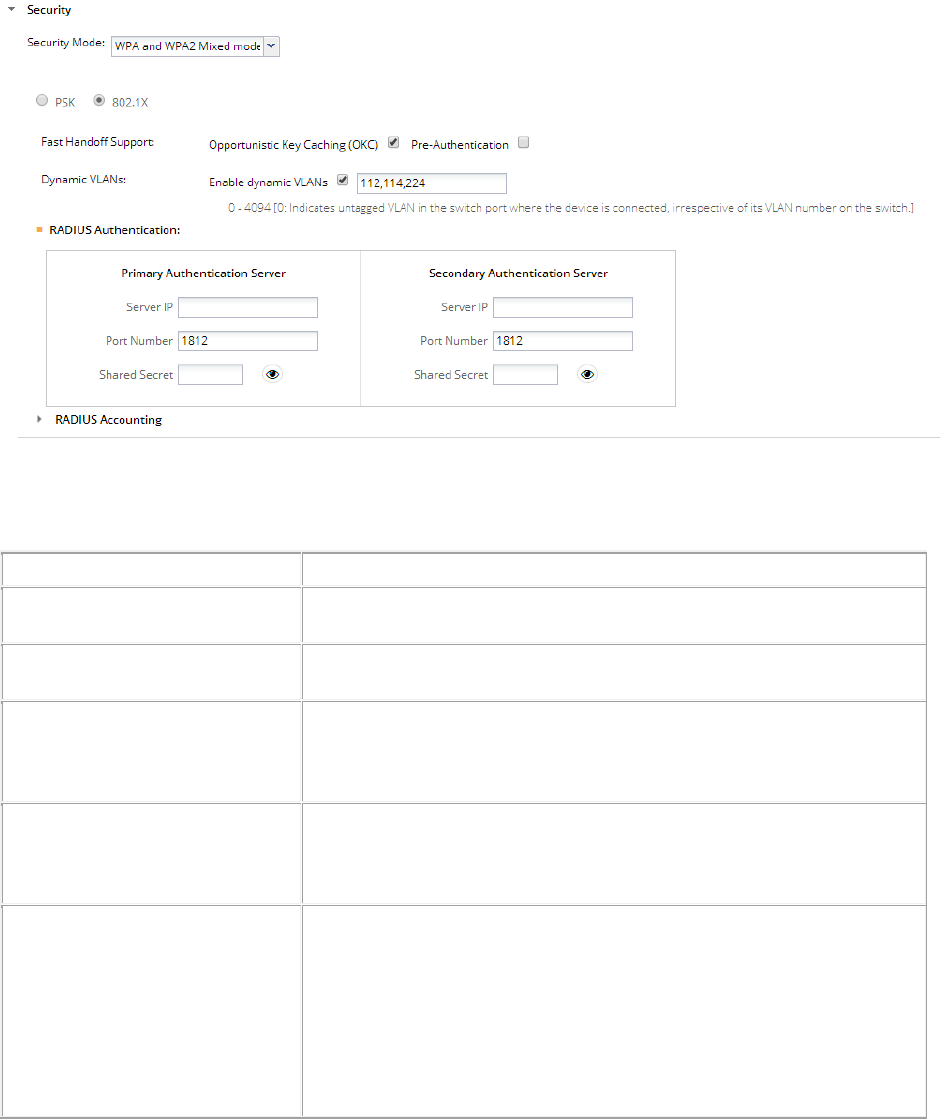
AirTight Management Console User Guide
46
The following image illustrates security settings.
The following table explains the fields present on the Add/Edit Wi-Fi profile and in the Security
Settings. Click Security Settings to view fields under Security Settings.
Field
Description
Profile Name
This field specifies the name of the
profile.
SSID
This field specifies the SSID of the wireless profile. This is a
mandatory field.
Broadcast SSID
This check box indicates whether the SSID is to be broadcast or not
for this Virtual AP, in the beacon frames. If selected, the beacon for
this Virtual AP carries the SSID.
Client Isolation
This check box indicates whether communication between 2 wireless
clients of this virtual AP is enabled or disabled. If selected, wireless
client communication
is disabled for the virtual AP.
Enable P2P
Cross Connection
Select this check box to enable to P2P cross connection bit. When a
client
is connected to a Wi-Fi direct network and to an AirTight AP in
an infrastructure network it is possible to bridge these two networks.
When you enable the P2P cro
ss connection bit, the Wi-Fi Direct
network and the infrastructure network can be bridged by the client.
Otherwise, the AP instructs the client not to cross
-connect the
infrastructure network to the
Wi
-Fi Direct network, thus enhancing the security of the wireless
network. The P2P cross connection is disabled, by default.

AirTight Management Console Configuration
47
Limit number of associations
This field specifies the maximum number of clients that can associate
with the AP. You can select the check box and then specify the
number of clients.
Security Mode
This specifies the security mode applied to the virtual AP.
The possible values are Open, WEP, WPA, WPA2, WPA and WPA2
mixed mode.
Fields related to security mode WEP
Authentication Type
Select
Open if the type of authentication is open. In case of open
authentication, the key is used for encryption only.
Select
Shared if the authentication type is shared key. In case of
shared key authentication, the same key is used for both encryption
and authent
ication.
WEP Type
Select WEP40 if 40-bit WEP security is used.
Select WEP104 if 104-bit WEP security is used.
Key Type
Select
ASCII option if you are comfortable with ASCII format and
want to enter WEP key in that format. The Sensor/AP combo
converts it to hexadecimal internally.
Select
HEX option if you are comfortable with hexadecimal format
and want to enter WEP key in that format.
Key
WEP key is a sequence of hexadecimal digits.
If WEP Type is WEP40, enter the key as a 5 character ASCII key or a
10 digit hexadecimal key, depending on the Key Type selected by
you.
If WEP Type is WEP104, enter the key as a 13 character ASCII key
or
a 26 digit hexadecimal key, depending on the Key Type selected
by you.
Show Key
Select this check box to see the actual key on the screen. If this
check box is cleared, the key is masked.
Fields related to security mode WPA/WPA2/WPA and WPA2 Mixed Mode
PSK
Select the
PSK option if you want to use a personal shared key. The
Pass phrase
field is enabled when this option is selected.
Pass Phrase
Specify the shared key of length 8-63 ASCII characters for PSK
authentication
Show Key
Select this check box
to see the actual pass phrase on the screen. If
this check box is cleared, the key is masked.
802.1x
Select 802.1x option if you want to use a RADIUS server for
authentication. The fields on the
Authentication and Accounting
tabs are enabled on selecting this check boxYou can enable dynamic
VLANs after selecting this check box.

AirTight Management Console User Guide
48
Opportunistic Key Caching
Select the check box to enable client fast handoffs using opportunistic
key caching method. Note that the key caching works
within the same
subnet only and not across subnets.
Pre
-authentication
Select the
Pre-Authentication check box to enable client fast
handoffs using the Pre
-Authentication method.
NAS ID
This field is used when a network access server (NAS) serves as a
single point to access network resources. Generally, a NAS supports
hundreds of simultaneous users. When a RADIUS client connects to
a NAS, the NAS sends access request packets to the RADIUS
server. These packets must contain either the NAS IP address or the
NAS identifier. The NAS ID or the NAS
-Identifier is used to
authenticate RADIUS clients with the RADIUS server.
You can specify a string for the NAS ID. The default value is %m
-%s,
where
%m represents the Ethernet MAC address of the AP and %s
represents the SSID of the WLAN. This corresponds to the NAS
-
Identifier attribute on the RADIUS server. The attribute ID for the
NAS
-Identifier RADIUS attribute is 32.
Ensure that the NAS ID is not
the same as the shared secret
configured for the RADIUS server in the RADIUS Authentication
section.
Enable dynamic VLANs
Select the check box to enable the AP to accept the VLAN for the
current user from the RADIUS server. When dynamic VLANs are
enabled, BYOD, firewall, portal and NAT features are disabled
for the
Wi
-Fi profile.
When the check box is selected, you can ente
r a list of dynamic
VLANs in the box adjoining this check box. The list of dynamic VLANs
must be a comma
-separated list of VLAN IDs. If the RADIUS server
does not return a VLAN ID or returns a VLAN ID that is not in the list
of dynamic VLANs configured in
the Wi-Fi profile, the AirTight AP
redirects the user traffic to the default VLAN (that is, the VLAN ID
specified in the Wi-Fi profile network settings).
Fields in the Authentication Tab-Primary RADIUS Server area
Server IP
Enter the IP Address of the
primary RADIUS server here.
Port Number
Enter the port number at which primary RADIUS server listens for
client requests.
Shared Secret
Enter the secret shared between the primary RADIUS server and the
AP.
Fields in the
Authentication Tab- Secondary RADIUS Server area
Server IP
Enter the IP Address of the secondary RADIUS server here.
Port Number
Enter the port number at which secondary RADIUS server listens for
client requests.
Shared Secret
Enter the secret shared between the secondary RADIUS
server and
the AP.
Field in the
Accounting Tab
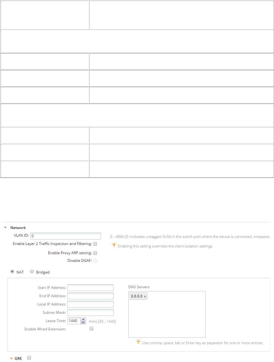
AirTight Management Console Configuration
49
Enable RADIUS Accounting
Select this check box to enable RADIUS Accounting. The other fields
on the Accounting tab are enabled on selecting this check box. Define
the primary RADIUS Server, and optionally se
condary RADIUS
Accounting server in the Accounting tab.
Fields in the
Accounting Tab- Primary Accounting Server area
Server IP
Enter the IP Address of the primary accounting server here.
Port Number
Enter the port number at which primary accounting server listens for
client requests.
Shared Secret
Enter the secret shared between the primary accounting server and
the AP.
Fields in the
Accounting Tab- Secondary Accounting Server area
Server IP
Enter the IP Address of the secondary accounting
server here.
Port Number
Enter the port number at which secondary accounting server listens
for client requests.
Shared Secret
Enter the secret shared between the secondary accounting server
and the AP.
Configure Network Settings for Wi-Fi Profile
Configure the VLAN and DHCP settings, to be used by the SSID profile, using the Network section.
The following image illustrates network settings
Network Settings

AirTight Management Console User Guide
50
A bridged network is used when the AP and the clients associating with the AP can be in the same
subnet.
Similarly, network Address Translation (NAT) must be used when you want to have the clients in a
separate subnet and the AP is in a separate subnet. With NAT, the clients can have a private IP address
pool and it is easier to add more clients to the network as they do not require a public IP address.
A wireless LAN, on which NAT is enabled, can be extended to the wired side using the second Ethernet
port present on the Access Point device. Create an isolated wired LAN with one or more wired devices
connected through layer-2 switches and connect the second Ethernet port of the Access Point to this
wired subnet. The wired LAN will be an extension of the wireless LAN of this SSID profile with NAT
enabled. All network settings like NAT and portal, configured on this SSID profile, are also applicable to
the wired devices.
Note: The second Ethernet port is available on some specific AirTight device models only.
When you are configuring NAT parameters, you must specify at least one DNS server. On successful
association, wireless clients will get the specified DNS servers. You can specify up to three such DNS
server IP addresses.
Generic Routing Encapsulation (GRE) is useful when you want to route network traffic from and to a
single end point and apply policies on this end point.
IMPORTANT: GRE works only when NAT is enabled.
To configure network address translation settings, do the following.
1. Specify the VLAN ID for which the bridging or NAT settings would be applicable.
2. Select the NAT check box if you want to enable NAT.
3. Specify the following NAT related settings if you have enabled NAT.
Field
Description
NAT
Select this check box to enable NAT (network address translation).
Enable NAT if you want to enable wired extension.
Start IP
address
The starting IP address of the DHCP address pool in the selected
network ID.
End IP
address
The end IP address of the DHCP address pool in the selected
network ID.
Local IP
address
An IP address in selected network ID outside of the DHCP address
pool. This address is used as the gateway address for the guest
wireless network.
Subnet Mask
The net mask for the selected network ID.
Lease Time
The DHCP lease time in minutes. Minimum value is 30
minutes,maximum value is 1440 minutes.
DNS Servers
The DNS servers that the wireless clients can make DNS queries to.
You can specify upto 3 DNS servers.
Enable
Wired
Extension
Select this check box to extend this wireless LAN to the wired side
using the second Ethernet port present on AirTight device functioning
as an access point.
4. Select GRE if you want to enable Generic Routing Encapsulation (GRE).
The following table describes the Generic Routing Encapsulation related fields
Field
Description
GRE
Select this check box to enable Generic Routing Encapsulation and to

AirTight Management Console Configuration
51
be able to define the GRE related parameters present on this page.
Tunnel IP
Address
IP address of the GRE tunnel interface on the access point. This IP
address should not conflict with any other network setting in the
access point.
Remote
Endpoint IP
Address
IP address of the remote endpoint of the GRE tunnel.
Key
Key in the GRE header. If configured, key should be same at both
ends of the tunnel. Key is not mandatory to be configured in GRE
tunnel.
Exempted
Host/Network
List
List of comma separated network and/or IP addresses that are
exempted from using the GRE tunnel.
5. Click Save to save the changes to the network settings.
Edit Network Settings
To edit network address translation settings, do the following.
1. Specify the VLAN ID for which the NAT settings would be applicable.
2. Deselect the NAT check box if you want to disable NAT and have a bridged network instead. In case
you want to continue using NAT and only want to edit NAT settings, edit them as required.
Field
Description
NAT
Select this check box to enable NAT (network address translation).
Start IP
address
The starting IP address of the DHCP address pool in the selected
network ID.
End IP
address
The end IP address of the DHCP address pool in the selected
network ID.
Local IP
address
An IP address in selected network ID outside of the DHCP address
pool. This address is used as the gateway address for the guest
wireless network.
Subnet Mask
The net mask for the selected network ID.
Lease Time
The DHCP lease time in minutes. Minimum value is 30
minutes,maximum value is 1440 minutes.
DNS Servers
The DNS servers that the guest clients can make DNS queries to.
Enable Wired
Extension
Select this check box to extend this wireless LAN to the wired side
using the second Ethernet port present on AirTight device functioning
as an access point.
3. Select the GRE check box if you want to enable Generic Routing Encapsulation (GRE).
The following table describes the Generic Routing Encapsulation related fields.
Field
Description
GRE
Select this check box to enable Generic Routing Encapsulation
and to be able to define the GRE related parameters present on
this page.
Tunnel IP Address
IP address of the GRE tunnel interface on the access point. This
IP address should not conflict with any other network setting in
the access point.
Remote Endpoint
IP address of the remote endpoint of the GRE tunnel.
AirTight Management Console User Guide
52
IP Address
Key
Key in the GRE header. If configured, key should be same at
both ends of the tunnel. Key is not mandatory to be configured in
GRE tunnel.
Exempted
Host/Network List
List of comma separated network and/or IP addresses that are
exempted from using the GRE tunnel.
In case you do not want to use GRE, disable the GRE check box.
4. Click Save to save the changes to the network settings.
Enable Layer 2 inspection and Filtering
L2 inspection and filtering prevents frames exchanged between two mobile devices from being delivered
by the Wi-Fi access network without first being inspected and filtered in either the hotspot operator
network or the Service Provider core network. Such processing provides some protection for mobile
devices against attack. The inspection and filtering mechanism is out of the scope of the Wi-Fi profile
settings,
If you want to inspect the packets exchanged between two clients in a Wi-Fi network on a wired side host,
do the following.
1. Select the Enable Layer 2 Traffic Inspection and Filtering check box.
2. Click Save to save the changes. You can use a packet capture tool to view the packets on the wired
side.
Inspection of layer 2 packets by AirTight AP is not supported.
Disable Downstream Group Addressed Forwarding
The purpose of the Downstream Group Addressed Forwarding (DGAF) Disable feature is to mitigate a
"hole-196” attack. By IEEE 802.11i design, all STAs in a BSS use the same GTK so forgery of group-
addressed frames is always possible. However, in some hotspots multicast service using group-
addressed frames is needed; in these cases, the DGAF Disable bit would be set to 0.
You must enable the proxy ARP setting to disable DGAF.
To disable DGAF and mitigate a hole-196 attack, do the following.
1. Select the Enable Proxy ARP Setting check box. The Disable DGAF check box is enabled.
2. Select the Disable DGAF check box to ensure future attacks that exploit the GTK can be mitigated.
3. Click Save to save the changes.
Enable/Disable DHCP Option 82
DHCP Option 82 is generally used in a distributed DHCP server environment where an AP inserts
additional information to identify the client point of attachment. The circuit ID represents the client point of
attachment. The DHCP Option 82 is available for a bridged SSID only.
When the DHCP option 82 is enabled and the AP receives DHCP packets from the client, a circuit ID is
appended by the AP to the DHCP packets from the client. It then forwards this DHCP request to the
DHCP server. Based on the circuit ID in the DHCP request, the DHCP server makes a decision on the IP
pool from which to assign an IP address to the client. When the DHCP assigns the IP address and
passes it to the AP, the AP passes it on to the client after stripping the circuit ID.
To enable DHCP Option 82 while creating or editing a Wi-Fi profile, do the following.
1. Under Network Settings, select the Bridged option.
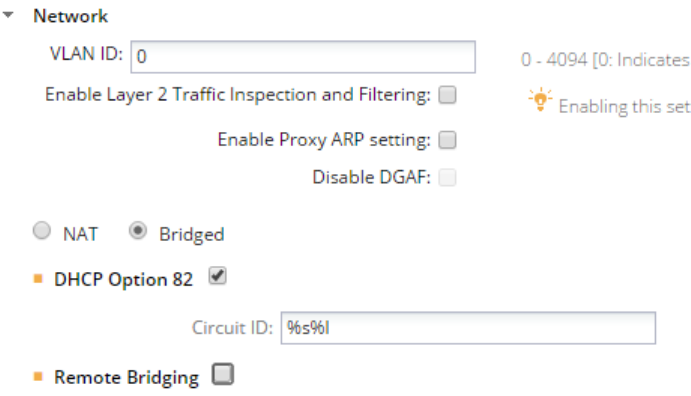
AirTight Management Console Configuration
53
2. Select the DHCP Option 82 check box.
3. Enter the Circuit ID.
You can use special formats %s, %m and %l.
% s is replaced by AP with the SSID.
%m is replaced by AP with the AP MAC address.
%l is replaced by AP with the location tag configured for the location to which the AP is assigned.
The location tag can be configured from Configuration>System Settings>Location Specific Attributes.
4. Click Save to save the changes.
The following image presents a sample DHCP Option 82 configuration in a Wi-Fi profile. Here the circuit
ID is constructed by replacing %s with the SSID and %l with the respective location tag.
The following image illustrates DHCP Option 82 related configuration.
To disable DHCP option 82, do the following.
1. Under Network Settings for a Wi-Fi profile, deselect the DHCP Option 82 check box.
2. Click Save to save the changes.
Enable/Disable Remote Bridging
To channelize all wireless traffic to a remote endpoint or gateway through a tunnel, you must enable
remote bridging. The remote endpoint or gateway aggregates wireless frames from different access
points and forwards them to the appropriate network.
You must configure a network interface profile before you enable remote bridging so that you can assign
the network interface profile to the SSID profile. When you enable remote bridging and assign a network
interface profile to the SSID profile, the wireless traffic from the AP is bridged to the remote endpoint
configured in the network interface profile. The traffic is rerouted to the appropriate network from this
remote endpoint.
When you disable remote bridging, the AP stops diverting the wireless traffic to the remote endpoint
configured in the network interface profile that was selected when remote bridging was enabled.
Remote bridging does not work with NAT.
To enable remote bridging, do the following.
1. Under Network Settings for a Wi-Fi profile, select the Bridged option.
2. Select the Remote Bridging check box.
3. Select a network interface profile from the Network Interface Profile.drop-down box.
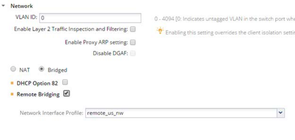
AirTight Management Console User Guide
54
4. Click Save to save the changes.
The figure below shows the remote bridging enabled and wireless traffic being diverted to a network
interface profile by the name ‘remote_us_nw’.
To disable remote bridging, do the following.
1. Under Network Settings for a Wi-Fi profile, deselect the Remote Bridging check box.
2. Click Save to save the changes.
Captive Portal Settings
A captive portal is a web page that a client on the network is directed to when the client wants to access
the Internet.
The client is authenticated on this page and is able to access the Internet after successful authentication.
A wireless profile can be configured to serve as a guest network to provide restricted wireless connectivity
(e.g., Internet only) to guest wireless clients. Multiple such guest networks are supported in AirTight Wi-Fi.
Supported Captive Portal Types
The following three types of captive portals are supported in AirTight Wi-Fi or AirTight WIPS.
1. AP hosted splash page with click through
2. External splash page for sign-in or click through
3. External splash page with RADIUS authentication
These are explained in detail below.
1. AP hosted splash page with click through: A ‘click-through’ splash page is a splash page where
authentication is not supported. The portal pages are hosted and served by the AP. The portal page can
be used to display the terms and conditions of accessing the guest network as well as any other
information as needed.
Steps involved in this type of access are as follows.
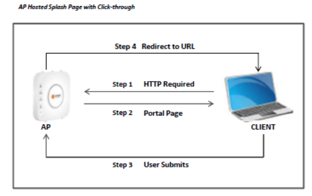
AirTight Management Console Configuration
55
(a) Wi-Fi user connects to the guest SSID and opens a URL from any web browser using the HTTP
protocol.
(b) AirTight AP intercepts this request and throws a portal page hosted on AP to guest user.
(c) Guest user will accept terms and condition and submits on portal page.
(d) AP will open gate for the client and client will be redirected to redirect URL (if any) or original
requested URL.
Following is a pictorial representation of AP hosted splash page with click through.
2. External Splash Page for Sign-In/Click-through: The portal is hosted on an external server.
The portal is either click-through without any authentication or has its own authentication mechanism
in place.
Steps involved in this type of access are as follows.
(a) Wi-Fi user connects to the guest SSID and opens a URL from any web browser using the HTTP
protocol.
(b) AirTight AP intercepts this request and redirects the browser to the configured external portal
page along with the request parameters as the GET parameters of the redirected URL.
(c) Portal will authenticate guest user by prompting sign-in or click-through splash page on wireless
user.
(d) After authentication, portal will redirect client to AP with success or failure reply. If AP and portal is
configured with shared secret. Portal will send validation code using which AP will validate reply
from Portal. Using shared secret between AP and portal would avoid fake user to get access using
spoofing attack.
(e) After successful validation AP will open gate for the client and client will be redirected to redirect
URL (if any) or original requested URL.
Following is a pictorial representation of External splash page for Sign-in/click-through
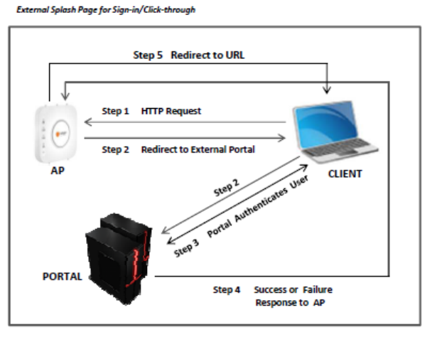
AirTight Management Console User Guide
56
3. External Splash Page with RADIUS Authentication: The guest user is redirected to a portal
hosted on an external server. The guest user is authenticated by a RADIUS server, when he logs in
to the external portal.
Steps involved in this type of access are as follows
(a) Wi-Fi user connects to the guest SSID and opens a URL from any web browser using the HTTP
protocol
(b) AirTight AP intercepts this request and redirects the browser to the configured external portal
page along with the request parameters as the GET parameters of the redirected URL.
(c) Portal will prompt the user with the splash page to enter username and password.
(d) User will submit username and password.
(e) Portal will redirect guest user to AP with username and encoded password using shared secret.
(f) Airtight AP will authenticate guest user by RADIUS server using username and decoded
password.
(g) RADIUS server will reply with Access Accept or Reject message for guest user.
(h) Airtight AP will open the Internet access for the client and redirect client to Redirect URL (if any) or
original requested URL.
Following is a pictorial representation of External splash page with RADIUS authentication.
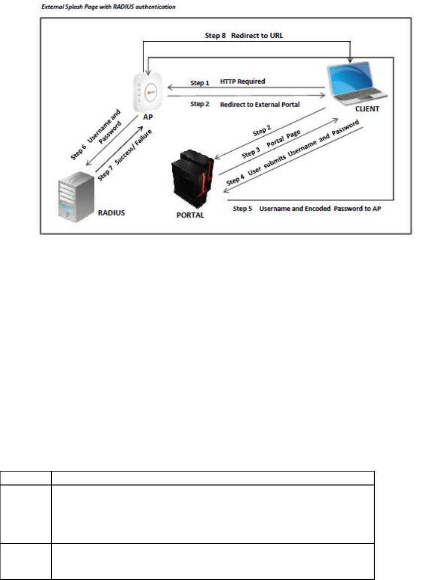
AirTight Management Console Configuration
57
Set up Walled Garden
A walled garden is a method to provide restricted access to the Internet. Walled garden destination(s) can
be accessed at the specified port numbers without displaying the splash page. Domain (e.g. domain.com)
also covers its subdomains (e.g. subdomain.domain.com).
Configure a list of exempted domains, subdomains, IP address ranges and port numbers. (E.g.
192.168.1.0/24) . Services on these IP addresses can be accessed without redirection to the portal
page. If some part of the portal page (e.g., images) is placed on a web server, the web server’s IP
address must be included in this list for the content to be successfully displayed.
If the mode of authentication is External Splash page for Sign-in/Click-through, you can restrict access to
walled garden destinations unless the guest user accepts the terms and conditions specified on the
splash page.
Do the following to set up a walled garden.
1. Click Add. The Add Destination dialog opens.
2. Enter the details.
Field
Description
Destination
domain name, sub domain name, host name, subnet or IP address to
which the rule applies.
You can provide a comma-separated list of more than one host names
here. For example, 192.168.8.173,
www.facebook.com,192.168.121.0/24.
Port
port number.
You can provide a comma-separated list of port numbers or port ranges
here. For example, 20-22, 81, 443.
3. To delete an exempted destination, select the entry and click Remove.
Configure Captive Portal Settings
AirTight Management Console User Guide
58
To configure captive portal settings, do the following.
1. Select the Enable Captive Portal check box to display a portal page to be shown to the client on
using the guest network.
2. Select the mode of access to the Internet through the captive portal. Do one of the following:
(a) Select the AP Hosted Splash Page with click through option. You must create a .zip file of the
portal page along with any other files like images, style sheets etc and upload this file. The zip file
must satisfy the following requirements for the portal to work correctly.
a. The zip file should have a file with the name “index.html” at the root level (i.e., outside of
any other folder). This is the main portal page. It can have other files and folders, (and
folder within folders) at the root level that are referenced by the index.html file.
b. The total unzipped size of the files in the bundle should be less than 100 KB. In case,
large images or other content is to be displayed on the page, this content can be placed
on an external web server with references from the index.html file. In this case, the IP
address of the external web server must be included in the list of exempt hosts (see
below).
c. The index.html file must contain the following HTML tags for the portal to work correctly:
• A form element with the exact starting tag: <form method="POST"
action="$action">
• A submit button inside the above form element with the name “mode_login”. For
example: <input type=”image” name=”mode_login” src=”images/login.gif”>The
exact tag: <input type="hidden" name="redirect" value="$redirect"> inside the
above form element.
You can download the factory default portal bundle file and use it as a template to create a
custom portal bundle. Click Download Sample to download the factory default portal bundle
file.
Upload the portal bundle (default or custom). Click Choose File following Upload Bundle to
upload the bundle.
Click Open to upload the portal bundle.
AirTight Management Console Configuration
59
To restore the portal bundle to factory default file, click Restore Default.
(b) Select the External Splash Page for Sign-in/Click-through option. Specify Splash Page URL,
using which wireless user will be redirected to external portal. This portal will prompt wireless
user to enter username and password. You must select the check box for the shared secret, if
applicable, and specify the shared secret for SSID-external portal communication.
If you want the guest user to accept the terms and conditions on the splash page before being
able to access walled garden destinations, select the Restrict access to Walled Garden check
box. If this check box is not selected, the guest user is able to access the walled garden
destinations without accepting the terms and conditions on the splash page.
(c) Select External Splash Page with RADIUS Authentication.
In this case, you also need to specify the following fields
Splash Page URL, using which wireless user will be redirected to external portal. You must enter a
shared secret for SSID-external portal communication. Click RADIUS settings hyperlink to configure
RADIUS server settings, using which the AP will actually authenticate the wireless user.
Specify the primary and optionally, secondary authentication server details.
Field
Description
Called station ID
a free form text parameter that the AP passes to the RADIUS
server in the standard RADIUS parameter,'Called
-Station-Id ',
dur
ing the authentication process. The special format specifier '
%m' can be specified which will be expanded to the Ethernet MAC
address of the AP.
NAS ID
This field is used when a network access server (NAS) serves as a
single point to access network
resources. Generally, a NAS
supports hundreds of simultaneous users. When a RADIUS client
connects to a NAS, the NAS sends access request packets to the
RADIUS server. These packets must contain either the NAS IP
address or the NAS identifier. The NAS ID o
r the NAS-Identifier is
used to authenticate RADIUS clients with the RADIUS server.
You can specify a string for the NAS ID. The default value is %m
-
%s, where %m represents the Ethernet MAC address of the AP
and %s represents the SSID of the WLAN. This co
rresponds to the
NAS
-Identifier attribute on the RADIUS server. The attribute ID for
the NAS
-Identifier RADIUS attribute is 32.
Ensure that the NAS ID is not the same as the shared secret
configured for the RADIUS server in the RADIUS Authentication
section.
Primary Authentication server details
Server IP
IP address of primary authentication server.
Port Number
port number of primary authentication server listens for client
requests.
Shared Secret
shared secret between the AP and primary authentication server.
Secondary authentication server details
Server IP
IP address of secondary authentication server.
Port Number
port number of secondary authentication server listens for client
requests.
Shared Secret
shared secret between the AP and secondary authentication
server.
If you want RADIUS accounting to be enabled, select the accounting check box and specify the
accounting details, using which AP will actually authenticate wireless user. InRADIUS Server
Settings specifyServer IPandPorton whichRADIUS server is running.
AirTight Management Console User Guide
60
Field
Description
Interval
Accounting interval, in minutes. Minimum interval can be 1 minute,
and maximum interval can be 60 minutes.
Primary accounting server details
Server IP
IP address of primary accounting server
Port
Number
Port number of primary accounting server listens for client
requests.
Shared Secret
Shared secret between the AP and primary accounting server.
Secondary accounting server details
Server IP
IP address of secondary accounting server.
Port Number
Port number of secondary accounting server listens for client
requests.
Shared Secret
Shared secret between the AP and secondary accounting server.
3. Configure the External Portal parameters. Refer to Configure External Portal Parameters below for
details.
4. Select the Roaming check box, if you don't want the Wi-Fi clients to see the splash page when they
roam from one AP to another.
5. Select the Enable Internet Connectivity Detection check box, if you want to check the internet
connectivity and display a portal error page in case of loss of Internet connectivity.
The 'Enable Internet Connectivity Detection' feature can be used to provide feedback to guests when
Internet is temporarily unavailable on the guest SSID. When the access point detects that Internet
connectivity is not available from the guest VLAN, it automatically redirects all HTTP requests of the
guest users to a splash page with a message that Internet is temporarily unavailable. When using the
AP Hosted Splash Page for Click-through option, a customized splash page included in the bundle
with the name “NoInternet.html” is displayed when Internet is down. If this page is not included in the
bundle or if external splash page options have been configured, the AP displays a factory default
splash page when internet is down.
Note that when Internet is down, guest users will not be able to access local HTTP services as well if
the Enable Internet Connectivity Detection feature is enabled.
The Enable Internet Connectivity Detection feature will not work for a SSID profile configured with
GRE.
6. Specify Login Timeout, in minutes, for which a wireless user can access the guest network after
submitting the portal page.
After the timeout, access to guest network is stopped and the portal page is displayed again. The
user has to submit the portal page to regain access to the guest network. If the user disconnects and
reconnects to the guest network before his session times out, he does not have to enter his
credentials on the splash page. If you are using AirTight Guest Manager and you have specified a
login timeout in AirTight Guest Manager, this login timeout overrides the Login Timeout setting in the
SSID profile.
7. Specify Blackout Time, in minutes. This is the time for which a user is not allowed to login after his
previous successful session was timed out.
For example, if the session time-out is 1 hour and the blackout time is 30 mins, a user will be timed
out one hour after a successful login. Now after this point, the user will not be able to login again for
30 minutes. At the end of 30 minutes, the user can login again.
8. Specify the Redirect URL. The browser is redirected to this URL after the user clicks the submit
button on the portal page.
If left empty, the browser is redirected to the original URL accessed from the browser for which the
portal page was displayed.
9. Specify the value of the Service Identifier that you have defined in Advanced Parameters. This is a
free form parameter that can be passed to the external portal.

AirTight Management Console Configuration
61
This parameter can be used by the external portal to implement SSID profile specific functionality. For
example, each SSID can have a separate portal page.
10. Click Save to save the settings.
Configure External Portal Parameters
You must configure the external portal parameters if you want to redirect users to a portal page hosted on
an external server.
All request and response attributes that are marked with an asterisk are mandatory. The request
parameters/attributes are sent from the AP to the external portal. The response parameters are sent from
the external portal to the AP. These parameters are used in the name - value pairs in the redirection URL.
The following table explains the request and response attributes in detail.
Request
Attributes
Description
Request Type
field name for request type field.
Challenge
field name for random text used for authentication.
Client MAC
field name for the MAC address of the client.
AP MAC Address
field name for MAC address of the access point that is
communicating with the external portal.
AP IP Address
field name for the IP address of the access point that is
communicating with the external portal. This should match the
field name used by the external portal.
AP Port Number
field name for the AP port number on which the AP and external
server communicate.
Failure Count
field name for the count of the number of failed login attempts.
Requested URL
field name for the requested URL that is the URL requested by the
client through the AP, to the external server.
Login URL
field name for the login URL.
Logoff URL
field name for the logoff URL.
Remaining Blackout
Time
field name for the remaining blackout time.
Service Idenitifier
name of the portal parameter that is used to pass the service
identifier value to the external portal. The service identifier value is
specified in the Captive Portal section of the SSID Profile. This
parameter can be used by the external portal to implement SSID
profile specific functionality like different portals for different SSIDs
etc.
Response
Attributes
Description
Challenge
field name for the challenge
Response Type
field name for the response type.
Challenge Response
field name for the challenge response.
Redirect URL
field name for the redirect URL
Login Timeout
field name for login timeout.
AirTight Management Console User Guide
62
User name
field name for user name.
Password
field name for password.
Note: The individual field names used by the AP should match the corresponding field
names used by the external server hosting the portal.
The AP and the external server may
not be able to communicate if the name of the same parameter is different on either si
de.
The fields in
External Portal Parameters facilitate the field name change on the AirTight
Wi-Fi / AirTight WIPS side.
Edit Captive Portal Settings
To edit captive portal settings, do the following.
1. Select the Enable Captive Portal check box to display a portal page to be shown to the client on
using the guest network.
2. Select the mode of access to the Internet through the captive portal. Do one of the following:
(a) Select the AP Hosted Splash Page with click through option. You must create a .zip file of the
portal page along with any other files like images, style sheets etc and upload this file. The zip file
must satisfy the following requirements for the portal to work correctly.
a. The zip file should have a file with the name “index.html” at the root level (i.e., outside of
any other folder). This is the main portal page. It can have other files and folders, (and
folder within folders) at the root level that are referenced by the index.html file.
b. The total unzipped size of the files in the bundle should be less than 100 KB. In case,
large images or other content is to be displayed on the page, this content can be placed
on an external web server with references from the index.html file. In this case, the IP
address of the external web server must be included in the list of exempt hosts (see
below).
c. The index.html file must contain the following HTML tags for the portal to work correctly:
• A form element with the exact starting tag: <form method="POST"
action="$action">
• A submit button inside the above form element with the name “mode_login”. For
example: <input type=”image” name=”mode_login” src=”images/login.gif”>The
exact tag: <input type="hidden" name="redirect" value="$redirect"> inside the
above form element.
You can download the factory default portal bundle file and use it as a template to create a
custom portal bundle. Click Download Sample to download the factory default portal bundle
file.
Upload the portal bundle (default or custom). Click Choose File following Upload Bundle to
upload the bundle.
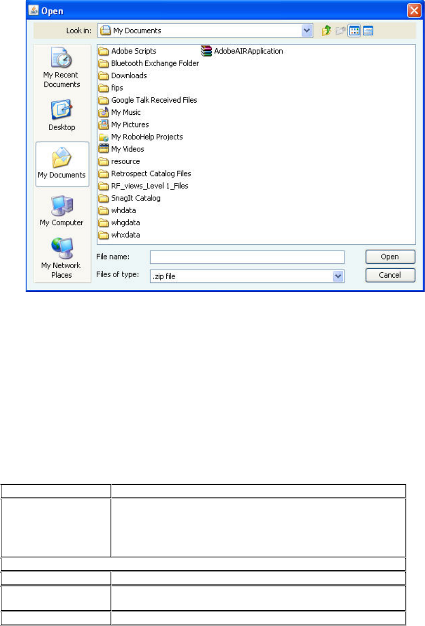
AirTight Management Console Configuration
63
Click Open to upload the portal bundle.
To restore the portal bundle to factory default file, click Restore Default.
(b) Select the External Splash Page for Sign-in/Click-through option. Specify Splash Page URL,
using which wireless user will be redirected to external portal. This portal will prompt wireless
user to enter username and password. You must select the check box for the shared secret, if
applicable, and specify the shared secret for SSID-external portal communication.
(c) Select External Splash Page with RADIUS Authentication.
In this case, you also need to specify the following fields
Splash Page URL, using which wireless user will be redirected to external portal. You must enter
a shared secret for SSID-external portal communication. Click RADIUS settings hyperlink to
configure RADIUS server settings, using which the AP will actually authenticate the wireless
user.
Specify the primary and optionally, secondary authentication server details.
Field
Description
Called station id
a free form text parameter that the AP passes to the RADIUS
server in the standard RADIUS parameter,'Called
-Station-Id ',
during the authentication process. The special format specifier '
%m' can be specified which will be
expanded to the Ethernet MAC
address of the AP.
Primary Authentication server details
Server IP
IP address of primary authentication server.
Port Number
port number of primary authentication server listens for client
requests.
Shared Secret
shared secret between the AP and primary authentication server.
AirTight Management Console User Guide
64
Secondary authentication server details
Server IP
IP address of secondary authentication server.
Port Number
port number of secondary authentication server listens for client
requests.
Shared
Secret
shared secret between the AP and secondary authentication
server.
If you want RADIUS accounting to be enabled, select the accounting check box and specify the
accounting details, using which AP will actually authenticate wireless user. In RADIUS Server
Settings specify Server IP and Port on whichRADIUS server is running.
Field
Description
Interval
accounting interval, in minutes. Minimum interval can be 1 minute,
and maximum interval can be 60 minutes.
Primary accounting server details
Server IP
IP address of primary accounting server.
Port Number
port number of primary accounting server listens for client
requests.
Shared Secret
shared secret between the AP and primary accounting server.
Secondary accounting server details
Server IP
IP address of secondary accounting server.
Port Number
port number of secondary accounting server listens for client
requests.
Shared Secret
shared secret between the AP and secondary accounting server.
3. Configure the External Portal parameters. Refer to Configure External Portal Parameters below for
details.
4. Select the Roaming check box, if you don't want the Wi-Fi clients to see the splash page when they
roam from one AP to another.
5. Select the Enable Internet Connectivity Detection check box, if you want to check the internet
connectivity and display a portal error page in case of loss of Internet connectivity.
The 'Enable Internet Connectivity Detection' feature can be used to provide feedback to guests when
Internet is temporarily unavailable on the guest SSID. When the access point detects that Internet
connectivity is not available from the guest VLAN, it automatically redirects all HTTP requests of the
guest users to a splash page with a message that Internet is temporarily unavailable. When using the
AP Hosted Splash Page for Click-through option, a customized splash page included in the bundle
with the name “NoInternet.html” is displayed when Internet is down. If this page is not included in the
bundle or if external splash page options have been configured, the AP displays a factory default
splash page when internet is down.
Note that when Internet is down, guest users will not be able to access local HTTP services as well if
the Enable Internet Connectivity Detection feature is enabled.
The Enable Internet Connectivity Detection feature will not work for a SSID profile configured with
GRE.
6. Specify Login Timeout, in minutes, for which a wireless user can access the guest network after
submitting the portal page.
After the timeout, access to guest network is stopped and the portal page is displayed again. The
user has to submit the portal page to regain access to the guest network. If the user disconnects and
reconnects to the guest network before his session times out, he does not have to enter his
credentials on the splash page. If you are using AirTight Guest Manager and you have specified a
login timeout in AirTight Guest Manager, this login timeout overrides the Login Timeout setting in the
SSID profile.
AirTight Management Console Configuration
65
7. Specify Blackout Time, in minutes. This is the time for which a user is not allowed to login after his
previous successful session was timed out.
For example, if the session time-out is 1 hour and the blackout time is 30 mins, a user will be timed
out one hour after a successful login. Now after this point, the user will not be able to login again for
30 minutes. At the end of 30 minutes, the user can login again.
8. Specify the Redirect URL. The browser is redirected to this URL after the user clicks the submit
button on the portal page.
If left empty, the browser is redirected to the original URL accessed from the browser for which the
portal page was displayed.
9. Specify the value of the Service Identifier that you have defined in Advanced Parameters. This is a
free form parameter that can be passed to the external portal.
This parameter can be used by the external portal to implement SSID profile specific functionality. For
example, each SSID can have a separate portal page.
10. Click Save to save the settings.
Disable Captive Portal
Deselect the Enable Captive Portal check box to disable captive portal settings.
Firewall Settings
A firewall controls the incoming and outgoing network traffic, based on a set of defined rules. Click
Firewall on the Add SSID Profile page to configure firewall settings for the SSID profile. You can add,
modify, reorder, and delete firewall rules from the Firewall section.
The firewall rules defined for the SSID profile are evaluated in a top down manner. That is,the first rule is
evaluated first, followed by the next rule, and so on, till a match is found for the respective host name and
direction.
When you create a SSID profile, you will notice that the default rule has been set to block all incoming
and outgoing requests from any host or domain. Define the default rule by selecting Allow or Block to
allow or block any type of requests from IP addresses, host names, subdomain names or domain names
for which no specific firewall rules have been defined.
To enable firewall for the SSID profile, select the Enable Firewall check box. If it has been previously
selected and you want to disable firewall for the SSID profile, deselect the Enable Firewall check box.
Add New Firewall Rule
Do the following to add a firewall rule.
1. Click Add New Rule.
2. If one or more rules have already been defined, select Above the selected rule or Below the
selected rule to insert the new rule above or below the selected rule, depending on how you want to
prioritize the rules.
3. Enter the rule details as specified in the following table.
Field
Description
Rule
Name
name of the rule
Host
domain name, sub domain name, host name, subnet or IP address to
which the rule applies.
You can provide a comma-separated list of more than one host names
AirTight Management Console User Guide
66
here. For example, 192.168.8.173,
www.facebook.com,192.168.121.0/24.
Port
port number.
You can provide a comma-separated list of port numbers or port
ranges here. For example, 20-22, 80, 443.
Action
if you want to block the traffic to or from the host option, select block. if
you want to allow traffic to or from the host, select allow.
Protocol
network protocol. The following options are available.
TCP: If the rule is for TCP-based communication, select the TCP
option.
UDP: If the rule is for UDP-based communication, select the UDP
option.
Other: If the rule is for a communication based on a protocol other
than TCP and UDP, select Other. You must specify the protocol
number in this case.
Any: If the rule is for communication that is not protocol specific, select
the Any option.
Protocol
No.
protocol number. This field appears only when the selected protocol is
Other
Direction
direction of network traffic. The following options are available.
Outgoing: If the rule is to be applied to data going out of your network,
that is, from wireless to wired, then select the Outgoing option.
Incoming: If the rule is to be applied to data coming into your network,
that is, from wired to wireless, select the Incoming option.
Any: If the rule is to be applied to both outgoing and incoming traffic,
select the Any option.
For instance, if you want to allow or prevent users of your wireless
network from accessing certain websites or domains, you can define
the respective rule with direction as Outgoing. Similarly, if you want
prevent certain hosts from accessing your wireless network, you can
define the rule specific to this host name or domain name with
direction as Incoming.
For example, if you want to allow all incoming and outgoing TCP requests from and to the host
'mail.google.com', ports 80, 25, 110, 465, 995, you will specify the rule details as follows.
Click Add New Rule to add the rule.
Specify an appropriate name for the rule in Rule Name.
Specify Host Name as 'mail.google.com, Port as 80, 25,110, 465, 995 Action as Allow, Protocol
as TCP, Direction as Any. See the image below for the rule.
Firewall Rule
4. Click Save to save the rule.
Reorder Firewall Rules
If you have more than 1 firewall rules defined, you can reorder them.
Do the following to reorder the rules.

AirTight Management Console Configuration
67
1. Click the rule to move.
2. Hold the mouse down and drag the rule to the desired position, for instance between 2 other rules.
3. Release the mouse. The rule is placed at the new position.
4. Click Save to save the rule reordering.
Edit Firewall Rule
Do the following to add a firewall rule.
1. Click the radio button for the rule to edit.
2. Edit the rule details as specified in the following table.
Field
Description
Rule
Name
name of the rule
Host
domain name, sub domain name, hostname or IP address to which the rule
applies.
You can provide a comma-separated list of more than one host names
here. For example, 192.168.8.173, www.facebook.com, 192.168.121.0/24.
Port
port number.
You can provide a comma-separated list of port numbers or port ranges
here. For example, 20-22, 80, 443.
Action
if you want to block the traffic to or from the host option, select block. if you
want to allow traffic to or from the host, select the allow option.
Protocol
network protocol. The following options are available.
TCP: If the rule is for TCP-based communication, select the TCP option.
UDP: If the rule is for UDP-based communication, select the UDP option.
Other: If the rule is for a communication based on a protocol other than
TCP and UDP, select Other. You must specify the protocol number in this
case.
Any: If the rule is for communication that is not protocol specific, select the
Any option.
Protocol
No.
protocol number. This field appears only when the selected protocol is
'other'
Direction
direction of network traffic. The following options are available.
Outgoing: If the rule is to be applied to data going out of your network, that
is, from wireless to wired, then select the Outgoing option.
Incoming: If the rule is to be applied to data coming into your network, that
is, from wired to wireless, select the Incoming option.
Any: If the rule is to be applied to both outgoing and incoming traffic, select
the Any option.
For instance, if you want to allow or prevent users of your wireless network
from accessing certain websites or domains, you can define the respective
rule with direction as Outgoing. Similarly, if you want prevent certain hosts
from accessing your wireless network, you can define the rule specific to
this host name or domain name with direction as Incoming.
Delete Firewall Rule
Do the following to delete a rule.
1. Click the Delete hyperlink for a rule to delete the rule.
2. Click Yes on the message that appears, to confirm the delete operation. To cancel the delete
operation click No.
AirTight Management Console User Guide
68
3. Click Save to save changes to the set of firewall rules.
Traffic Shaping & QoS
Effective utilization of network bandwidth can be achieved in various ways.
Some of the ways in which you can do this is by setting an upload and download limit for the network,
restricting the number of client association, band steering and defining QoS parameters. You can opt for
one or more of these ways depending on the network traffic, the applications used on the SSID, and the
AirTight device model in use.
Band Steering
When an SSID is configured in both 2.4 GHz and 5 GHz bands, clients that are capable of both bands
(b/g/n and a/n) and are operating in one of the bands, can be steered towards the other band to balance
the load on the AirTight AP.
This load balancing feature is called band steering. It is available in dual-radio access point models.
It helps in evenly distributing the Wi-Fi clients between the two bands.
Band steering works in a bi-directional manner, steering clients from 2.4 GHz to 5 GHz radio or from 5
GHz to 2.4 GHz radio, to balance the load on the AirTight AP.
Clients connecting to an AP will be steered from 2.4 GHz to 5 GHz or 5 GHz to 2.4 GHz when all the
following conditions are satisfied.
• Band steering is enabled on the SSID profile that the client is associated with.
• Client RSSI is equal to and above the RSSI threshold mentioned in Traffic Shaping and QoS
settings for SSID profile.
• The number of clients on one radio are not more than clients on the other radio plus the Spectrum
Load Balancing threshold defined in the device template (under Radio Advanced Settings) applied
to the AP, counted among all SSIDs associated with the AP.
When you enable band steering, you need to specify the RSSI threshold of the clients. This is required
due to the fact that clients with weak signal strength cannot operate effectively in the 5 GHz band and
hence should not be steered even if they are capable of operating in 5 GHz.
To configure band steering, do the following.
1. Select the Enable Band Steering check box.
2. Specify the RSSI Threshold of the client.
3. Click Save to save the changes.
Traffic shaping
You can limit the upload and/or download bandwidth on an SSID.
To restrict the upload bandwidth on the SSID, do the following.
1. Select Restrict upload bandwidth on this SSID to check box and enter a data rate, from 0 through
1024 Kbps, to restrict the upload bandwidth for the SSID to the value specified here.
2. Click Save to save the changes.
To restrict the download bandwidth on the SSID, do the following.
1. Select Restrict download bandwidth on this SSID to check box and enter a data rate, from 0
through 1024 Kbps, to restrict the download bandwidth for the SSID to the value specified here.
2. Click Save to save the changes.

AirTight Management Console Configuration
69
Large enterprises, sometimes, use RADIUS attributes to propagate network policies across multiple
points of access. Users are divided into groups, and policies are applied to each group to effectively
control access to network resources. Each user group is assigned an upload bandwidth and a download
bandwidth, based on the need of that user group. For instance, the Sales user group would be assigned
upload and download bandwidths that differ from the upload and download bandwidths assigned to the
HR user group.
In case of clients authenticated using a RADIUS server, you can configure the AirTight AP to retrieve and
use the bandwidth control settings defined by the RADIUS server. The unit for bandwidth is Kbps.
Based on the values returned by the RADIUS server, the AirTight AP dynamically sets the upload and
download bandwidths for the RADIUS-authenticated user. If the RADIUS server does not return a value
for the bandwidths, the default upload and download bandwidth defined in the Traffic Shaping and QoS
settings are used. If a user has more than one devices, the bandwidth limit is applied separately on each
of these devices. This means that if a user uses 2 devices, and the bandwidth for the user or the user
group is 4 Mbps, 4 Mbps is the bandwidth limit applied to each of these devices.
User-specific bandwidth values can come from one or more of the following.
• From portal with external RADIUS authentication server.
• From GAMS portal.
• From the RADIUS server, if SSID is configured with 802.1x security.
• From AirTight server- If no value is returned by either of the above, the default value defined by
AirTight server is used.
If bandwidth values are returned by more than one of the above-mentioned sources, the order of
precedence to identify the bandwidth limit to apply is the same as mentioned above. That is, external
RADIUS authentication server has the highest priority followed by GAMS portal, and then RADIUS server
used for 802.1x authentication.
The default AirTight server bandwidth value is used only if none of the other sources return a bandwidth
value.
To enable RADIUS-based assignment of bandwidth based on the user group of the RADIUS user, do the
following.
1. Navigate to Configuration>Device Configuration>SSID Profile.
2. On the Wi-Fi profile tab, add or edit a Wi-Fi profile.
3. Click Traffic Shaping & QoS. The section expands.
4. Select the Enable per User Traffic Control check box. The fields for Restrict user upload
bandwidth to and Restrict client down load bandwidth to appear.
5. To specify a default bandwidth value for upload bandwidth, select the check box for Restrict user
upload bandwidth to and specify a value between 0 and 1024 Kbps. This is used when no upload
bandwidth is returned by the RADIUS server for the RADIUS user.
6. To specify a default bandwidth value for download bandwidth, select the check box for Restrict user
download bandwidth to and specify a value between 0 and 1024 Kbps. This is used when no
download bandwidth is returned by the RADIUS server for the RADIUS user.
The RADIUS user attributes used to set per user bandwidth fall under vendor specific attributes-IETF ID
:26. The vendor ID for AirTight is 16901.
The following table shows the mapping of the AirTight attributes with the RADIUS attributes.
AirTight attribute
RADIUS attribute ID
AirTight Per User Download Limit
5

AirTight Management Console User Guide
70
AirTight Per User Upload Limit
6
Limit Clients associating with the AP
You can limit the number of clients associating with the AP to restrict the network bandwidth.
To limit the number of clients associating with the AP, do the following.
1. Select the Limit number of associations check box if you want to specify the maximum number of
clients that can associate with the AP.
2. Specify the maximum number of clients in the field next to the Limit number of associations check
box.
3. Click Save to save the changes.
Define Minimum Data Rate
You can specify the minimum data rate for the AP-client communication. Data rates greater than the
specified data rate are used to communicate with clients.
To specify a minimum data rate, do the following.
1. Select the Minimum data rate check box.
2. Specify the minimum data rate for communication in the field adjacent to the Minimum data rate
check box.
3. Click Save to save the changes.
Quality of Service (QoS)
The priority of various types of traffic is defined in QoS. QoS stands for quality of service. The service
guarantee is imperative in case of streaming multimedia applications, for example, voice over IP, video,
online games etc. It is necessary to define the priority when the network bandwidth is shared for such
applications. You must define the QoS parameters if you are using the SSID for such applications. QoS
ensures that applications or traffic requiring higher priority gets the required priority. The service
guarantee for the service being provided is met by allocating adequate bandwidth based on the QoS
priority.
If you configure the radio in 11N mode, WMM (Wi-Fi multimedia) will always be enabled, because WMM
is mandatory in 11N mode.
In 11N mode, if the QoS check box is not selected, the system uses the default QoS parameters.
The default QoS settings are as follows.
o SSID priority is voice.
o Priority type is ceiling.
o Downstream marking is DSCP.
o Upstream marking is enabled and the value is 802.1p marking.
The system uses the user-configured QoS settings if the QoS check box is selected.
To configure QoS settings, do the following.
1. Select the QoS check box and define your own QoS settings for Wi-Fi multimedia on the SSID profile.
2. Specify voice, video, best effort or background as the SSID Priority depending on your requirement.
3. Select Priority Type as Fixed if all traffic of this SSID has to be transmitted at the selected priority
irrespective of the priority indicated in the 802.1p or IP header. Select Priority Type as Ceiling if
traffic of this SSID can be transmitted at priorities equal to or lower than the selected priority.
4. Select the Downstream mapping option if Priority Type is selected as Ceiling. The priority is
extracted from the selected field (802.1p, DSCP or TOS) and mapped to the wireless access
category for the downstream traffic subject to a maximum of the selected SSID Priority. For the
downstream mappings, the mapping depends on the first 3 bits (Class selector) of the DSCP value,
AirTight Management Console Configuration
71
TOS value or 802.1p access category. The only exception will be DSCP value 46 which will be
mapped to WMM access category 'Voice'.
5. Select the Upstream marking option as per the requirement. The incoming wireless access category
is mapped to a priority subject to a maximum of the selected SSID priority and set in the 802.1p
header and the IP header as selected.
6. Click Save to save the changes.
Refer to the following table for downstream mapping.
802.1p Class of
Service
802.11e/WMM access
category
0 (Background)
1 (Background)
1 (Best Effort)
0 (Best Effort)
2 (Excellent Effort)
3 (Best Effort)
3 (Critical Apps)
4 (Video)
4 (Video)
5 (Video)
5 (Voice)
6 (Voice)
6 (Internetwork
Ctrl)
7 (Voice)
7 (Network Ctrl)
7 (Voice)
Refer to the following table for the priority, 802.11e/WMM access category and the corresponding 802.1p
Class of Service and DSCP value, used for upstream marking. If 802.1p marking is enabled, the
802.11e/WMM access category maps to the corresponding 802.1p Class of Service. If DSCP/TOS
marking is enabled, the 802.11e access category maps to the corresponding DSCP value.
802.11e/WMM
access
category
802.1p Class of
Service
DSCP
0
1
0
1
0
10
2
0
18
3
2
0
4
3
26
5
4
34
6
5
46
7
6
48
BYOD - Device Onboarding
Device onboarding is a technique in which unapproved clients that are quarantined by the system are
redirected to a configured splash page URL upon making any web access while all other communication
is blocked. This technique can be enabled for all clients or selectively for smart clients, that is,
smartphones and tablets only.
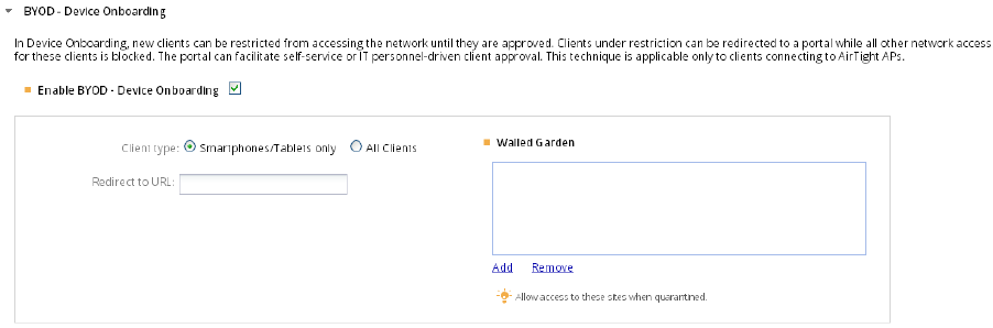
AirTight Management Console User Guide
72
BYOD - Device Onboarding
To configure BYOD device onboarding, do the following.
1. Select the Enable Device Onboarding check box to enable BYOD device onboarding.
2. Select Smartphones/Tablets Only if you want this technique to be enabled for unapproved smart
clients only, and not for other wireless clients (like laptops etc.). Alternatively,select All Clients if you
want to enable this technique for all types of unapproved wireless clients.
3. Specify the URL of the splash page in Redirect to URL. Wireless clients will be redirected to this
URL upon making any web request. The IP address or hostname of the splash page host must be
added to the walled garden settings for the redirection to work.
4. Configure walled garden settings. Click Add to add IP addresses or hostnames to the walled garden.
Click Remove to remove IP addresses or hostnames from the walled garden. Any other hostname or
IP address that needs to be exempted from redirection, can also be added here.
5. Click Save to save the changes.
Hotspot 2.0 Settings
Hotspot 2.0 provides automatic network discovery and selection with little or no user intervention. It
facilitates cellular offload and Wi-Fi roaming, without the overhead to sign in to the Wi-Fi network
manually. The handoff is automatic and is transparent to the mobile user using a Wi-Fi Alliance
Passpoint-certified mobile device such as laptop, handheld device, smart phone etc.
Passpoint-certified mobile devices can seamlessly connect to an AirTight AP, if the Wi-Fi profile applied
on the AP has Hotspot 2.0 enabled and the corresponding settings configured in it. After Hotspot 2.0
settings configured Wi-Fi profile is applied on the AirTight AP deployed at the operator location, the AP
can advertise available network services enabling Passpoint-certified mobile devices to automatically
discover and select a Wi-Fi network.
A mobile device can request a Hotspot 2.0 AP for information related to the capabilities and services
provided by the AP, without associating with the AP. Based on the information received from the AP, it
can decide whether it wants to connect to the AP or not. This communication between the AP and the
mobile devices takes place using the Access Network Query Protocol (ANQP).
The Hotspot 2.0 settings for the AP correspond to the ANQP elements sent to a querying mobile device
by the Hotspot 2.0 AP to which the Wi-Fi profile is applied.
IMPORTANT! Hotspot 2.0 works only with WPA2 802.1x enterprise security. If you want to configure
Hotspot 2.0 functionality, you must first set the value in the security mode field (under Security Settings in
the Wi-Fi profile) as WPA2 and ensure that the 802.1x option is selected.
AirTight Management Console Configuration
73
The Hotspot 2.0 settings for an AirTight AP are divided into general settings, roaming consortium list,
venue settings, domain name list, 3GPP Cellular network info list, NAI realm list, WAN metrics, Operator
Friendly Name List, connection capability.
General Settings
The General Settings refer to the network configuration. It includes the network access type, network
authentication type element, IP address type etc.
The network type is a predefined list and can have one of the following values.
• Private network- Unauthorized users are not permitted on this network. Examples of this access
network type are home networks and enterprise networks, which may employ user accounts.
• Private network with guest access- The network is a private network offering guest access. An
example of this access network type is an enterprise network with guest access.
• Chargeable public network- A public network that is available to everyone for a charge. An
example of this access network type is a hotel offering in-room Internet access service for a fee.
• Free public network- A public network that is available to everyone for free. An example of this
access network type is an airport hotspot.
• Personal device network - A network of personal devices such as a camera connecting to a printer
thereby forming a network to print pictures.
• Emergency services only network- The network is dedicated and limited to accessing emergency
services only.
• Test or experimental- The network is a test or experimental network only.
• Wildcard- Wildcard access network type. Select this option if you want the AP to reply to the client
(mobile device) irrespective of the access network type requested for in the client query.
The network authentication element refers to the list of authentication types. This element is related to
captive portal based authentication systems. A redirect URL can be specified in the General Settings to
redirect the mobile user to the appropriate URL on connecting to the AP.
The network authentication element is a predefined list and can have one of the following values.
• Acceptance of terms and conditions- Select this option if the network requires the user to accept a
set of terms and conditions. You can provide a URL that points to the terms and conditions page in
the Redirect URL field. Providing redirect URL is optional.
• Online enrollment- Select this option if online enrolment is supported by the network.
• http/https redirection- Select this option if the network infrastructure perform http/https redirection.
You can optionally provide a redirect URL for http/https redirection.
• DNS redirection- Select this option if the network supports DNS redirection.
• Not configured- Select this option if you don't want to provide specific information when the client
queries about network authorization type.
The Homogenous ESSID (HESSID) is a MAC address that is the same for all APs belonging to the same
network. APs with the same HESSID have the same Hotspot 2.0 configuration.
IPv4 address type and IPv6 address type are specified under General Settings.
Roaming Consortiums Element
The roaming consortiums element is configured under Roaming Consortium List. The network could be
member of a roaming consortium or could support service providers. The element consists of one of more
organization identifiers that are unique hexadecimal strings. If this element contains multiple organization
identifiers, it means the network supports multiple service providers or consortia.
AirTight Management Console User Guide
74
Venue Settings
The Venue Settings specify the configuration of the venue details where the AP is to be deployed. You
can configure zero or more venues. The venue settings consist of venue groups and venue types. The
venue group is selected from a predefined list of values. The venue type is dependent on the venue
group and the list of values for the venue type is populated based on the venue type selected. You can
select a venue type for the venue group from the list of relevant values for the selected venue group.
The available venue groups are as follows.
• Assembly: An arena or an amusement park is a place where a group of people assemble together.
Select this venue group if the AP is deployed at such a location.
• Business: If the AP is deployed on business premises such as a bank or an office,select this venue
group.
• Educational: If the AP is deployed at an educational institution such as a school or a university,
select this venue group.
• Factory and Industrial: If the AP is deployed at a factory or industrial location, select this venue
group.
• Institutional: If the AP is deployed at a venue hosptial or a rehabilitation center, select this venue
group.
• Mercantile: If the AP is deployed at a mercantile venue such as a gas station or a shopping mall,
select this venue group.
• Residential: If the AP is deployed at a residential location such as a hotel or a private residence,
select this venue group.
• Storage: If the AP is deployed at a storage facility, select this venue group.
• Utility and Miscellaneous: If AP is deployed at a utility or miscellaneous location, select this venue
group
• Vehicular: If the AP is deployed on a vehicle such as a train or a boat, select this venue group.
• Outdoor: If the AP is deployed at an outdoor location such as a kiosk or a bus stop, select this venue
group.
Domain Name List
The Domain Name List provides a list of the Hotspot 2.0 operator domain names.
3GPP Cellular Network Info List
The list of mobile networks supported by the AP can be configured under 3GPP Cellular Network Info
List.
NAI Realm List
The NAI Realm List corresponds to the NAI realm element. The NAI realm element provides a list of
network access identifier (NAI) realms corresponding to service providers or other entities whose
networks or services are accessible through the AP. A list of one or more EAP Methods is optionally
included for each NAI realm.
WAN Metrics
Under WAN metrics, you can specify details of the WAN connection available through the WLAN. The link
status and the uplink and downlink speeds can be specified under WAN metrics. Under operator friendly
name list, you can enter a list of operator friendly names along with the language code in which they are
provided to AirTight Management Console.
Connection Capability

AirTight Management Console Configuration
75
Under connection capability, you can specify the protocols supported by the network connection and the
corresponding port numbers and whether the port is open or closed. These settings signify the
capabilities of the wired network that the AP is connected to. They provide information on the connection
status of the most commonly used communication protocols and ports within the hotspot.
Configure Hotspot 2.0 Settings
To configure Hotspot 2.0 Settings, do the following.
1. Select the Hotspot 2.0 tab in the Add Wi-Fi Profile or Edit Wi-Fi Profile dialog box.
2. Configure the General Settings.
Field
Description
Network
Type
Select the appropriate network type that the AP is a part of, from the list of
available options.
Network
Auth Type
Select the network authentication type from the list of available options.
IPv4
Address
Select the appropriate IPv4 address type from the available options. The
following options are available.
Address type not available
Public IPv4 address available
Port-restricted IPv4 address available
Single NATed private IPv4 address available
Double NATed private IPv4 address available
Port-restricted IPv4 address and single NATed private IPv4 address
available
Port-restricted IPv4 address and double NATed private IPv4 address
available
For NAT related options, NAT must be enabled on the Wi-Fi profile.
Internet
Access
Select this check box if the network provides Internet access to the client
through the AP.
HESSID
Homogenous Extended Service Set Identifier. This is an optional field
used to identify hotspot APs. APs with the same HESSID have the same
Hotspot 2.0 configuration.
Redirect
URL
URL to which the user is to be redirected on connecting to the AP. This
field is used in conjunction with network authentication type.
IPv6
Address
Select the appropriate IPv6 address type from the available options. The
following options are available
Address type not available
Address type available
Availability of address type not known
3. Enter the roaming consortium list using hex characters. The first 3 roaming consortium from
the list are advertised in the beacon. Up to 32 roaming consortiums can be added here. The
length of the roaming consortium string must be 3 or 5 bytes, that is 6 or 10 hex characters.
4. Enter the venue details as described in the following table and click Add for each venue
information that you add.
Field
Description
Venue
Group
Select the appropriate venue group from the available options.
Venue
Type
Select the type of venue at which the AP is installed. Different options are
presented based on the venue group selected.
For example, when you select the venue group as Educational, the

AirTight Management Console User Guide
76
Field
Description
options available for Venue type are unspecified Educational; School,
Primary; School, Secondary; and University or College
Venue
Name
Name of the venue. Maximum length is 252 bytes. Up to 32 venue names
can be added.
Language
Code
The language code in which the service is to be provided. Refer to the ISO
639.2 standard for the language codes.
5. Enter domain name of the Hotspot 2.0 operator. Click Add to add it. You can enter multiple
domain names in this manner. A maximum of 32 domains can be added. The size of the
domain name must not exceed 255 bytes.
6. Under 3GPP Cellular Network Info List, enter the 3 digit mobile country code, the 2-3 digit
mobile network code and click Add to add to the list. You can add up to 32 entries here.
7. Enter the NAI Realm and click Add. You can add upto 32 such realms, each with length upto
255 bytes.
8. Select the EAP method for that realm and click Add. You can add upto four EAP methods for
one realm. You can see the EAP methods specified for a particular realm when you click the
EAP Settings link for that Realm in the Realm box. The EAP methods must be added in the
sequence of preference. The most preferred EAP method must be added first, followed by the
second prefered method and so on.
9. Enter the WAN metrics as described the table below.
Field
Description
Link Status
Select the appropriate option. The following options are available.
Link
up- Select this option if the link is up.
Link down
- Select this option if the link is down.
Link in test
- Select this option if the link is under test.
Not Configured- Select this option when the link status is not configured.
Symmetric
Link Status
Select the Same option if the uplink and downlink speeds are the same.
Select the
Different option if the uplink and the downlink speeds are
different.
Downlink
Speed
Downlink speed, in Kbps or Mbps. Select the appropriate unit of
measurement of the speed
after entering the value for the downlink
speed.
Uplink Speed
Uplink speed, in Kbps or Mbps. Select the appropriate unit of
measurement of the speed after entering the value for the downlink
speed.
10. Enter the operator friendly name list details. You can have up to 32 entries in the list.
Field
Description
Name
The operator friendly name of the Hotspot 2.0 operator in different
languages. The maximum length must not be more than 252 bytes.
Language
Code
The language code in which the operator friendly name has been specified.
Refer to the ISO 639.2 standard for the language codes.
11. Enter the connection capability details for the network to which the mobile device connects or
requests information from. Based on the port configuration, ensure that you have configured
an appropriate firewall rule in the firewall settings of the Wi-Fi profile. Refer to the following
screenshots for an example of the connection capability and the corresponding rule under
firewall settings. In the connection capability, the port is closed for ICMP requests. The
complementary firewall rule prevents ICMP requests that might result in a denial-of-service
attack. The protocol number 1 in the firewall rule refers to ICMP.
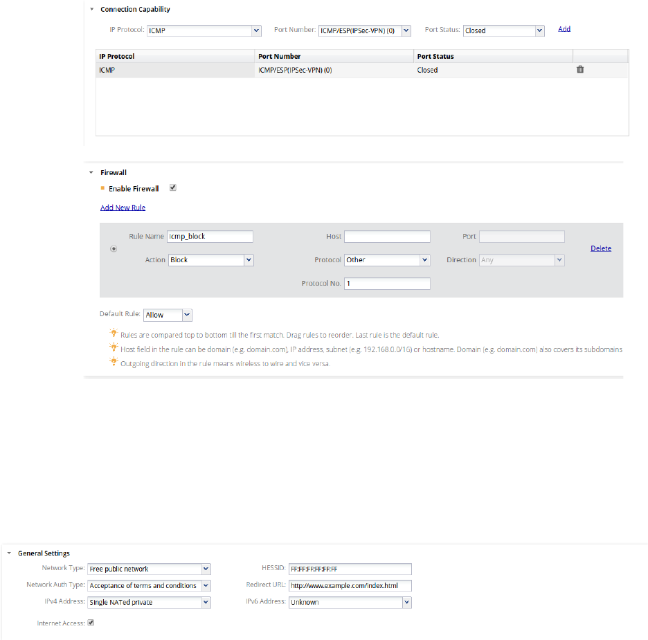
AirTight Management Console Configuration
77
12. Click Save. The Wi-Fi profile with the Hotspot 2.0 settings is saved.
The following image is an example of the Hotspot 2.0 configuration.
It describes a Hotspot 2.0 AP that is a part of a free public educational network at the Aalto University. It
is accessible on acceptance of certain terms and conditions. It provides Internet access and the mobile
device is redirected to the URL www.example.com/index.html when it connects to the AP and the mobile
user attempts to access the Internet. The domain names for the operator are exampleoperator.com and
exampleoperator.org. The other settings are as mentioned in the image.
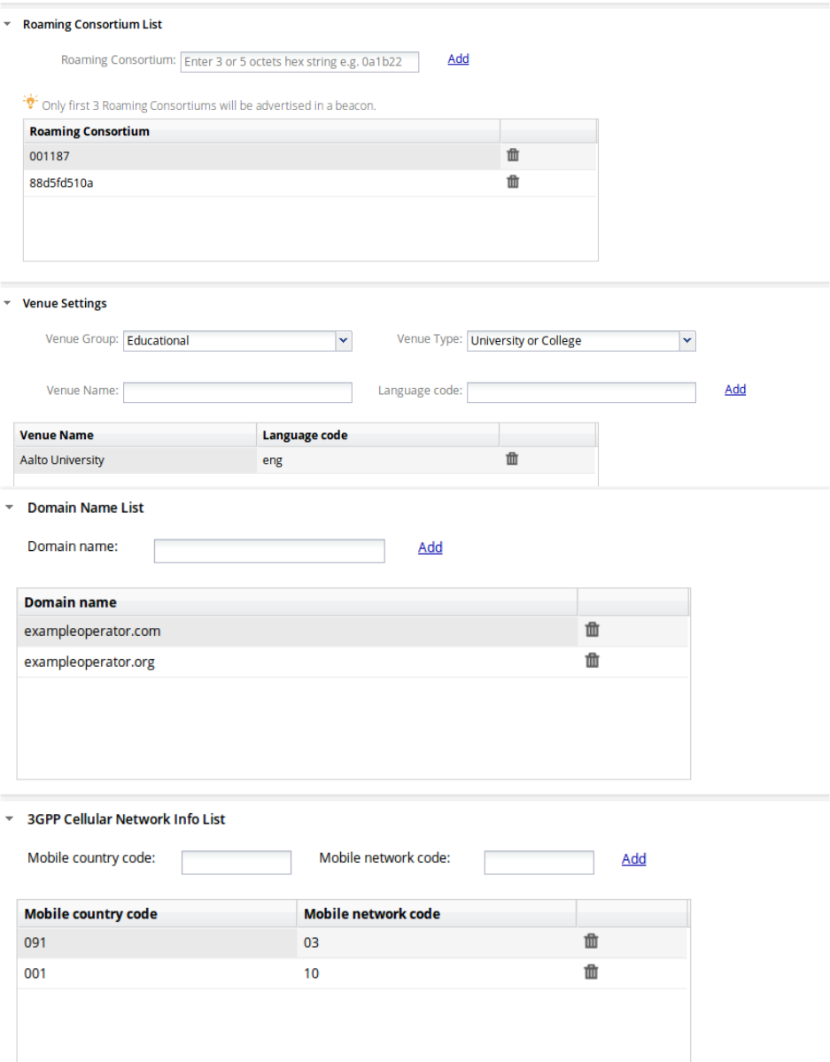
AirTight Management Console User Guide
78
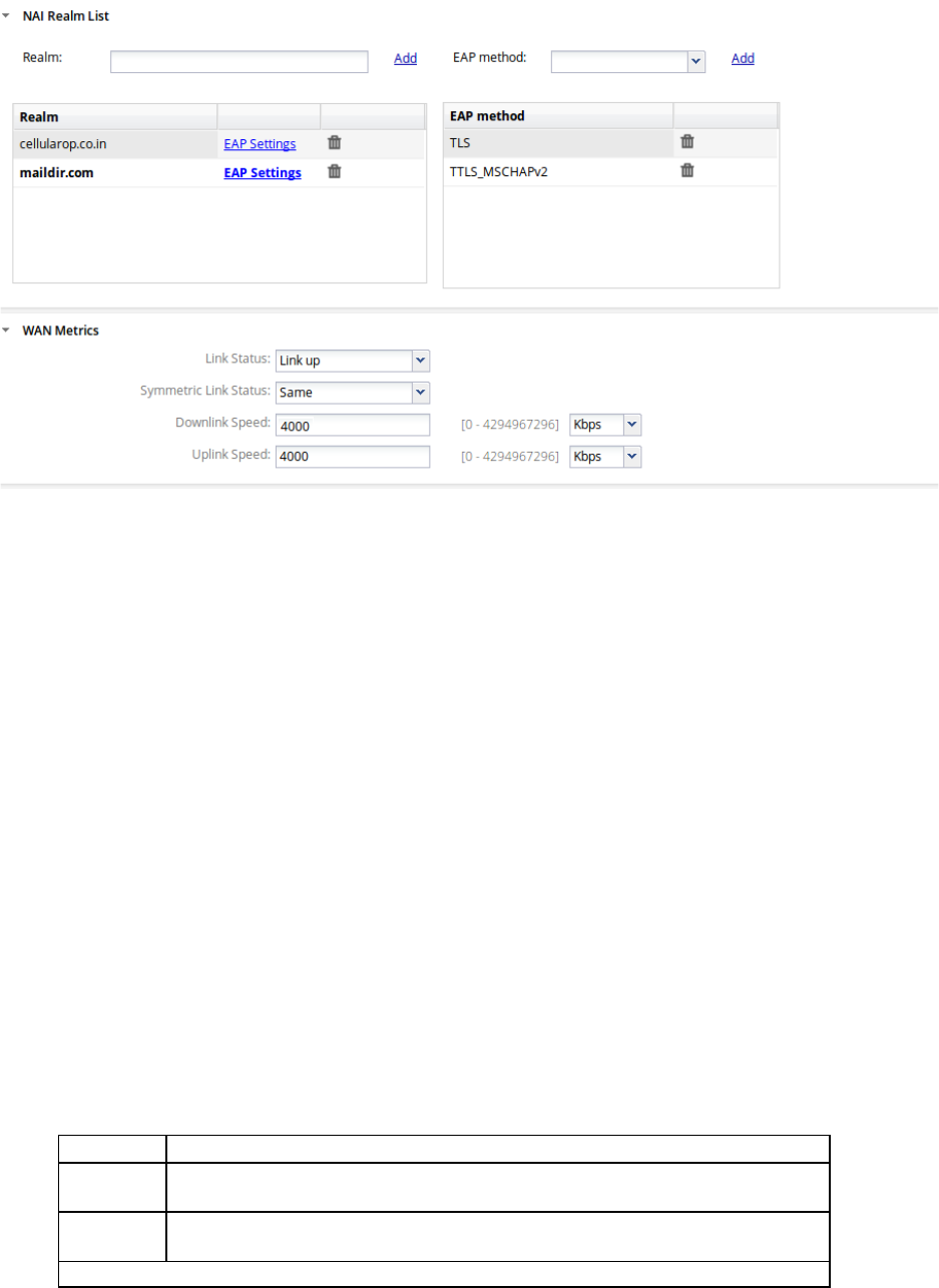
AirTight Management Console Configuration
79
Manage Network Interface Profiles
A network interface profile represents the tunnel through which network traffic from the configured SSIDs
can be routed to a remote endpoint. The remote endpoint then reroutes this traffic to their respective path
or destination. A network interface profile is used to configure Ethernet over GRE (EoGRE)
settings. Generic Routing Encapsulation (GRE) is a tunneling protocol that can encapsulate a variety of
network layer protocols inside virtual point-to-point links over an IP internetwork. EoGRE provides the
ability to setup one or more tunnels from the access point to an aggregating device. Traffic from one or
multiple SSIDs can be channeled through such tunnels. Multiple such tunnels can be configured.
When you configure network interface profiles, you can specify a primary endpoint and a secondary
endpoint. The wireless traffic is bridged to the secondary endpoint if the primary endpoint fails. The
secondary endpoint is optional and is functional only if you enable a secondary endpoint and configure
the host name and local endpoint VLAN for the secondary endpoint.
The secondary endpoint checks for the availability of the primary endpoint and transfers control to the
primary endpoint once it is up and running.
A network interface profile must be attached to an SSID profile when you enable remote bridging on the
SSID profile.
Add Network Interface Profile
To add a network interface profile, do the following.
1. Go to Configuration>Device Configuration>Network Interfaces.
2. Enter the values for the network interface profile fields.
Field
Description
Profile
Name
Name of the network interface profile. It can have a maximum length of
260 bytes.
Tunnel
Type
Select Tunnel Type as Ethernet over GRE.
Basic Parameters (or Primary Endpoint Parameters)

AirTight Management Console User Guide
80
Field
Description
Remote
Endpoint(IP
Address)
The IP address of the primary remote server or endpoint. It can be left
blank, if you want to use NTP server IP (from DHCP option 42) as the
remote endpoint.
Local
Endpoint
VLAN
The VLAN ID through which AP will form tunnel to the remote endpoint. .
A value between 0 and 4094 should be entered here. Remote Endpoint
must be reachable through this VLAN.
Secondary Endpoint Related Parameters
Enable
Secondary
Endpoint
Secondary endpoint is remote endpoint to which the wireless traffic is
diverted if the primary endpoint goes down.
Select this check box if you want to enable a secondary endpoint.
Remote
Endpoint(IP
Address)
The IP address of the secondary remote server or endpoint. It can be left
blank, if you want to use NTP server IP (from DHCP option 42) as the
remote endpoint.
Local
Endpoint
VLAN
The secondary VLAN ID through which the wireless network traffic is to be
routed. A value be
tween 0 and 4094 should be entered here. Remote
Endpoint must be reachable through this VLAN.
Network
Probe
Interval
The interval, in seconds, after which the AP checks connectivity with
remote endpoint by sending a ping request packet. This can have a va
lue
between 10 and 3600. The interval must be a multiple of 10.
Network
Ping Retry
Count
Count of ping request packets that the AP sends to the remote
endpoint.
The default value is 3.
Network
Ping
Timeout
Time, in seconds, till which the AP waits for a
ping reply. The default value
is 60 seconds.
Prefer
Primary
Tunnel
over
Secondary
Tunnel
Select the check box if you want the AP to check for the availability of the
primary tunnel. If the check box is not selected and the primary tunnel is
down, the AP
continues to operate on the secondary tunnel.
Ethernet over GRE
GRE
Primary
Key
Key in the primary endpoint GRE header. If configured, key should be
same at both ends of the tunnel. Key is not mandatory to be configured in
GRE tunnel
GRE
Secondary
Key
Key in the secondary endpoint GRE header. If configured, key should be
same at both ends of the tunnel. Key is not mandatory to be configured in
GRE tunnel
3. Click Save to save the network interface profile.
Edit Network Interface Profile
To edit a network interface profile, do the following.
1. Go to Configuration>Device Configuration>Network Interfaces.
2. Make the necessary changes.
Field
Description
Profile Name
Name of the network interface profile. It can have a maximum
length of 260 bytes.
Tunnel Type
Select Tunnel Type as Ethernet over GRE.
Basic Parameters (or Primary Endpoint Parameters)

AirTight Management Console Configuration
81
Field
Description
Remote Endpoint(IP
Address)
The IP address of the primary remote server or endpoint. It can
be left blank, if you want to use NTP server IP (from DHCP
option 42) as the remote endpoint.
Local Endpoint VLAN
The VLAN ID through which AP will form tunnel to the remote
endpoint. A value between 0 and 4094 should be entered here.
Remote Endpoint must be reachable through this vlanVLAN.
Secondary Endpoint Related Parameters
Enable Secondary
Endpoint
Secondary endpoint is remote endpoint to which the wireless
traffic is diverted if the primary endpoint goes down.
Select this check box if you want to enable a secondary
endpoint.
Remote
Endpoint(IP Address)
The IP address of the secondary remote server or endpoint. It
can be left blank, if you want to use NTP server IP (from DHCP
option 42) as the remote endpoint.
Local Endpoint VLAN
The secondary VLAN ID through which the wireless network
traffic is to be routed. A value between 0 and 4094 should be
entered here. Remote Endpoint must be reachable through this
VLAN.
Network Probe
Interval
The interval, in seconds, after which the AP checks
connectivity with remote endpoint by sending a ping request
packet. This can have a value between 10 and 3600. The
interval must be a multiple of 10.
Network Ping Retry
Count
Count of ping request packets that the AP sends to the remote
endpoint.
Network Ping Timeout
Time, in seconds, till which the AP waits for a ping reply.
Prefer Primary Tunnel
over Secondary
Tunnel
Select the check box if you want the AP to check for the
availability of the primary tunnel. If the check box is not
selected and the primary tunnel is down, the AP continues to
operate on the secondary tunnel.
Ethernet over GRE
GRE Primary Key
Key in the primary endpoint GRE header. If configured, key
should be same at both ends of the tunnel. Key is not
mandatory to be configured in GRE tunnel
GRE Secondary Key
Key in the secondary endpoint GRE header. If configured, key
should be same at both ends of the tunnel. Key is not
mandatory to be configured in GRE tunnel
3. Click Save to save the changes.
Change Location for Network Interface Profile
To move the network interface profile to another location, do the following.
1. Go to Configuration>Device Configuration>Network Interfaces.
2. Select the location at which the network interface profile has been defined.
3. Select the check box for the network interface that you want to move to another location.
4. Click the change location icon. The Select Location dialog box appears.
5. Select the new location and click OK. The network interface is moved to the new location.
AirTight Management Console User Guide
82
Print Network Interface Profile
You can print all the information seen for all network interface profiles. You can choose the columns to be
viewed on the UI by selecting them.
To print the network interface profiles' list for a location, do the following.
1. Go to Configuration>Device Configuration>Network Interfaces.
2. Select the location for which you want to print the network interface profiles' list.
3. Select the columns that you want in the printed list. Click any column name to select or deselect
columns.
4. Click the print icon. The print preview of the network interface profiles' list appears.
5. Click Print to print the list.
Filter/Search Network Interface Profiles
You can filter the network interface profiles' list based on the profile name or tunnel type.
To filter a network interfaces profiles' list, do the following.
1. Go to Configuration>Device Configuration>Network Interfaces.
2. Enter the search/filter criteria in the Quick Search box. You may enter the profile name or the tunnel
type to filter the network interface profile data.
3. Press the Enter key. The network interface profiles matching the search/filter criteria are seen in the
list.
To select the columns to be made visible on the Network Interfaces page, do the following.
1. Go to Configuration>Device Configuration>Network Interfaces.
2. Click a column heading. A down arrow appears at the right of this column.
3. Click the down arrow.
4. Select Columns option from the menu that appears.
5. Select the check boxes for the individual columns that are to be made visible on the Network
Interfaces page.
Delete Network Interface Profile
You can delete one or more network interface profiles at the same location at a time.
To delete a network interface profile, do the following.
1. Go to Configuration>Device Configuration>Network Interfaces.
2. Select the location for which you want to delete the network interface profile.
3. Select one or more network interface profiles to delete and click the bin icon the toolbar.
A message asking to confirm deletion of network interface profile appears.
4. Click Yes to confirm the deletion.
Manage Mesh Profiles
A wireless mesh network is a network where multiple access points (APs) interconnect and communicate
with each other over a wireless link to replace most of the wired connections. The communication
between the APs and routing of network data takes place through the AP radios. The APs that form the
wireless mesh network are the mesh APs.

AirTight Management Console Configuration
83
Wireless mesh networks are used indoors or outdoors where laying a wired network may not be a cost-
effective option. They can be used in specific areas where there is a need to be connected to the network
while moving around in the specified area. They can be used in stadiums, schools, military
establishments etc.
The source mesh AP communicates with the destination mesh APs in the same mesh directly or through
a series of hops from one mesh AP to another until the destination mesh AP is reached. The
communication between wireless clients and APs, and communication between APs takes place through
wireless or wired networks.
AirTight devices with AP capability support creation of a wireless mesh network. A wireless mesh
network, created using AirTight devices, consists of root and non-root APs.
A root AP is an AP that is directly connected to the wired network. A non-root AP is an AP that is not
directly connected to the wired network. It connects to the wired network through the root AP. A non-root
AP can communicate with the root AP directly, or through another non-root AP. There could be one or
more than one root APs and multiple non-root APs in the wireless mesh network.
The root AP connects to a AirTight Wi-Fi/WIPS server through the wired network. All the clients and other
non-root mesh APs talk to the AirTight Wi-Fi/WIPS server through the root AP.
AirTight device models with two radios that are capable of operating in AP mode, that is, SS-300-AT-C-
55, SS-300-AT-C-55-E, SS-300-AT-C-60, SS-300-AT-O-70, C-75, C-75-E and C-65 support mesh
networking. One radio is used as a dedicated mesh radio and the other radio is used to offer Wi-Fi access
to wireless clients. This also means that mesh networking is currently supported for a/n and b/g/n
platforms, but not supported on the 802.11ac platform.
A mesh network created using AirTight devices is logically implemented as a tree topology.
In a tree topology, there is a parent node and there are multiple child nodes. The child node is referred to
as a downlink in the mesh profile configuration. The parent node of a child is referred to as an uplink.
Set up a Mesh Network
To set up a wireless mesh network, you must first identify the APs that would behave as mesh APs. The
APs could be a combination of different AirTight device models supporting mesh networking, or multiple
devices of a single AirTight device model.
You must define a mesh profile on the AirTight Wi-Fi server if you wish to set up a wireless mesh network.
A mesh profile represents the mesh network parameters. You can add, edit and delete mesh profiles.
The mesh profile defined for the wireless mesh network must be applied to one of the radios of the mesh
APs. This radio acts as the dedicated radio to communicate with the other APs on the mesh network.
You must apply a device template with per device configuration enabled, to all the mesh APs. Then, you
must specify which of the mesh APs are root APs. The other APs in the mesh will be treated as non-root
APs, by default.
Once you have defined the mesh parameters and overridden the device template settings for the mesh
AP, you will be able to see a pictorial representation of the mesh network topology in the Locations
section on the AirTight Management Console. For details on viewing the mesh network topology, refer to
the 'View Mesh Topology' section in Manage Location Layout.
IMPORTANT! You cannot create a wireless mesh network that is a combination of AirTight APs and APs
from vendors other than AirTight. The mesh network must consist of AirTight APs only.
To set up a wireless mesh network for a location, do the following.
1. Select a location from the location tree.
AirTight Management Console User Guide
84
2. Go to Configuration>Device Configuration>SSID Profiles>Mesh Profiles.
3. Configure a mesh profile. Refer to the Add Mesh Profile given below for adding a mesh profiles.
4. Go to Configuration>Device Configuration>Device Template.
5. Define a device template for the AirTight device models that are to function as mesh APs. Refer to
Manage Device Templates for details. Remember to enable the device-specific configuration for this
device template. Ensure that the channel on which the mesh APs are to communicate with each other
is the same for all the AirTight device models that are a part of the wireless mesh network. You must
select the channel manually.
6. Go to Radio Settings under Device Template. Select the mesh profile configured in one of the
previous steps mentioned in this procedure.
7. Configure other device template details and click Save to save the device template.
8. Connect all the AirTight devices that are to function as mesh APs to the wired network. You must
connect all Airtight devices irrespective of whether they are root or non-root APs.
9. Apply the device template to all the devices that are to function as mesh APs.
10. Disconnect the non-root APs from the wired network. Keep the root APs connected to the wired
network.
11. Go to Devices>AirTight Devices. Specify the root AP or APs in the wireless mesh network. For
further details on specifying the root and non-root APs, refer to Override Device Template Settings
section. You are done with configuring the mesh network.
Add Mesh Profile
IMPORTANT!:Configuration of mesh profile on both radios is not supported. Configuration of mesh profile
on one radio and WIPS mode on another radio of an AirTight device is not supported. DFS channels are
not available when you manually select channels on the radio on which mesh profile is configured.
To add a mesh profile, do the following.
1. Go to Configuration>Device Configuration>SSID Profiles>Mesh Profiles.
2. Select a location from the location tree. A list of mesh profiles available at the location, if any, is seen
in Mesh Profiles.
3. Click Add New Mesh Profile.
4. Specify the mesh profile parameters.
Field
Description
Profile Name
Name of the mesh profile.
SSID
SSID of the mesh profile. This is the network name of the
mesh network.
Max Hop Count
Maximum number of hops in which the wired network can be
reached. For instance, the number of hops for a root AP would
be 0 as it is directly connected to the wired network. Similarly,
the hops for a non
-root AP directly communicating with the
root AP it is 1.
Max downlinks
Maximum number of mesh APs that can directly connect to a
non
-root or root AP in the mesh network. This indicates the
maximum number of child nodes that a parent node can have
in the mesh tree topology. You can enter a value between 0
and 5.
Min RSSI
Minimum RSSI for an AP to connect to another AP in the
mesh. An AP requesting to connect to another AP should
have the specified RSSI to be able to connect to the other AP.
You can enter a value between -100 and 0 dbm.
5. Click Save to save the newly added mesh profile.

AirTight Management Console Configuration
85
Edit Mesh Profile
To edit a mesh profile, do the following.
1. Go to Configuration>Device Configuration>SSID Profiles>Mesh Profiles.
2. Select the location of the mesh profile to be edited, from the location tree. A list of mesh profiles
available at the location is seen in Mesh Profiles.
3. Click the name of the mesh profile to edit.
4. Edit the mesh profile parameters.
Field
Description
Profile Name
Name of the mesh profile.
SSID
SSID of the mesh profile. This is the network name of the
mesh network.
Max Hop Count
Maximum number of hops in which the wired network can be
reached. For instance, the maximum number of hops for a
root AP would be 0 as it is directly connected to the wired
network. Similarly, the maximum hops for a non
-root AP
directly communicating with the root AP it is 1.
Max downlinks
Maximum number of mesh APs that can directly connect to a
non
-root or root AP in the mesh network. This indicates the
maximum number of child nodes that a parent node can have
in the mesh tree topology. You can enter a
value between 0
and 5.
Min RSSI
Minimum RSSI for an AP to connect to another AP in the
mesh. An AP requesting to connect to another AP should
have the specified RSSI to be able to connect to the other AP.
You can enter a value between -100 and 0 dbm.
5. Click Save to save the changes to the mesh profile.
Create Copy of Mesh Profile
You can create a copy of a mesh profile and use it as a distinct mesh profile by making minor
modifications to it.
To create a copy of a mesh profile, do the following.
1. Go to Configuration>Device Configuration>SSID Profiles>Mesh Profiles.
2. Select the location of the mesh profile from the location tree. A list of mesh profiles available at the
location is seen in Mesh Profiles.
3. Click the name of the mesh profile to save with another name.
4. Change the name of the mesh profile. Change any other parameters as required.
Field
Description
SSID
SSID of the mesh profile. This is the network name of
the mesh network.
Max Hop Count
Maximum number of hops in which the wired network
can be reached. For instance, the maximum number of
hops for a root AP would be 0 as it is directly connected
to the wired network. Similarly, the maximum hops for a
non
-root AP directly communicating with the root AP it is
1.
Max downlinks
Maximum number of mesh APs that can directly connect
to a non
-root or root AP in the mesh network. This
indicates the maximum number of child nodes that a
AirTight Management Console User Guide
86
parent node can have in the mesh tree topology. You
can enter a value between 0 and 5.
Min RSSI
Minimum RSSI for an AP to connect to another AP in the
mesh. An AP requesting to connect to another AP
should have the specified RSSI to be able to connect to
the other AP. You can enter a value between
-
100 and 0
dbm.
5. Click Save to save the changes to the mesh profile.
Copy Mesh Profile to Another Location
To copy a mesh profile from one location to another, do the following.
1. Go to Configuration>Device Configuration>SSID Profiles>Mesh Profiles.
2. Select the location at which the mesh file to copy has been created. A list of mesh profiles at the
location is displayed.
3. Select the mesh profile to be copied to another location.
4. Click the Copy to location icon. The Select Location dialog box appears.
5. Select the location to which you want to copy the mesh profile.
6. Click OK. A copy of the selected mesh profile is created at the selected location.
Print List of Mesh Profiles for Location
You can print a list of mesh profiles that have been defined for a location.
To print a list of mesh profiles at a location, do the following.
1. Go to Device Configuration>SSID Profiles>Mesh Profiles tab.
2. Select the columns that you want in the printed list. Click any column name to select or deselect
columns.
3. Click the Print icon. A print preview of the list appears.
4. Click Print to print the list.
Delete Mesh Profile
You cannot delete a mesh profile that is in use.
To delete a mesh profile, do the following.
1. Go to Configuration>Device Configuration>SSID Profiles>Mesh Profiles.
2. Select the location at which the mesh file to delete has been created. A list of mesh profiles at the
location is displayed.
3. Select the mesh profile to be deleted.
4. Click the Delete icon. A message asking to confirm deletion of the mesh profile appears.
5. Select Yes to confirm deletion and delete the mesh profile.
AirTight Management Console Configuration
87
Configure Event Notification
The occurrence of certain events needs to be notified to external entities like Syslog, SNMP, Arcsight and
OPSEC. This configuration is done using the Configuration->Events->Configuration option.
Different types of events occur when the WLAN is functional. These are classified as security,
performance and system events by AirTight Management Console.
Each of these types is listed in the respective tab on the Configuration page.
Security events indicate security vulnerability or breach in your network. Security events are further
classified as follows.
• Misconfigured AP events
• DoS events
• Reconnaissance events
• Rogue AP events
• Man-in-the-middle events
• Ad hoc events
• Cracking events
• MAC spoofing events
• Misbehaving clients events
• Prevention events
Performance events indicate problems in the wireless network. Performance events are further classified
as follows.
• Coverage events
• Configuration events
• Bandwidth events
• Interference events
System events indicate the system health. System events are further classified as follows.
• Troubleshooting events
• Sensor events
• Server events
There are multiple events under each of the security, performance and system event sub-categories.
Some events need to be displayed on the console when they occur. Users or administrators need to be
notified by email when certain events occur. Configure the settings for the events occurring in AirTight
Management Console using the Configuration page.
Do either or all of the following to configure settings for individual events in either of the tabs Security,
Performance, and System, based on your requirement.
• Select the Display check box that corresponds to the event that you want to appear on the
Events page.
• Select the Email check box that corresponds to the event for which you want to send e-mail
notifications to users configured under Configuration->Events->Email Recipients.
• Select the Notify check box that corresponds to the event for which you want notifications sent to
external agents such as SNMP, Syslog, ArcSight, and OPSEC.
• Select the Vulnerability check box that corresponds to the event that makes the WLAN
vulnerable. If any of these events occur, the Security Status widget on the Dashboard displays
the status as Vulnerable.
• Select the option High, Medium, or Low based on the severity of each event.
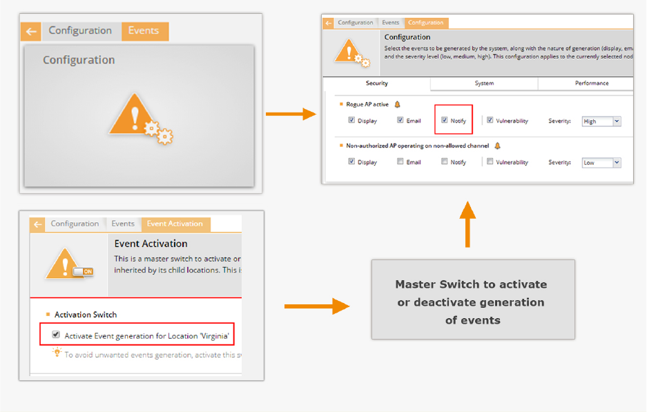
AirTight Management Console User Guide
88
Note: The event 'Client RF Signature Anomaly Detected' that is visible under Security>MAC Spoofing
option is available in specific deployments only.
Activate Event Generation for Location
Activate event generation for the selected location using the Configuration>Events>Event Activation
option.
Activation Switch defines the high level administrative settings for the selected location. It takes
precedence over any conflicting policies.
Event generation does not happen unless you select the Activate Event Generation for Location
<selected location> check box.
The following figure explains event generation activation.
Activate Event Generation
IMPORTANT: This policy cannot be inherited from the parent- it is specific to the location.
It is recommended that the deployment be stable and fully configured before you select the Activate
Event Generation for Location <selected location> check box.
Click Save to save the changes made to the page. Click Cancel to cancel the unsaved changes on the
page. Click Restore Defaults to restore the default values of the fields on the page.
AirTight Management Console Configuration
89
Configure Email Recipients
Specify the e-mail addresses of the users that need to be notified on occurrence of certain events at the
selected location. The events for which e-mail is to be sent are configured under Configuration->Events-
>Email Recipients.
You can use the e-mail addresses available in the system or add an e-mail address that is not available in
the system.
Separate all the e-mail addresses using a comma or a space, or press Tab or Enter. Click Save to save
the changes made to the page. Click Cancel to cancel the unsaved changes on the page. Click Restore
Defaults to restore the default values of the fields on the page.
Configure Device - Server Communication Settings
Go to Configuration>System>Advanced Settings>Device Communication Key, to set or reset the
communication key used for the communication between the AirTight devices and the AirTight
Management Console server. The communication key is also used to encrypt the communication
between the AirTight devices and server. The communication can happen either using a key or using a
pass phrase.
Use Key for Device - Server Communication
You can set the key for the communication between AirTight devices and the AirTight server directly in
hexadecimals. Select this option if you are comfortable working with hexadecimals.
To set a hexadecimal key for device-server communication, do the following.
1. Go to Configuration>System>Advanced Settings>Device Communication Key.
1 Select the Key option to use a key for the communication.
2 Enter a 32 digit hexadecimal key in Enter Key.
3 Enter the same key again in Confirm Key.
4 Click Set to save the changes.
Use Passphrase for Device - Server Communication
You can set an alphanumeric passphrase for the communication between AirTight devices and the
AirTight server. Select the Passphrase option if you are not comfortable working with hexadecimals.
To set an alphanumeric passphrase for device-server communication, do the following.
2. Go to Configuration>System>Advanced Settings>Device Communication Key.
5 Select the Passphrase option to use a key for the communication.
6 Enter an alphanumeric passphrase in Enter Passphrase.
7 Enter the same passphrase again in Confirm Passphrase.
8 Click Set to save the changes.
Reset Communication Key
Click Restore Defaults to reset the communication key.
AirTight Management Console User Guide
90
Manage Policy Templates
Policy templates form a part of the authorized WLAN policy for a location. A policy template comprises
properties of the authorized SSIDs or networks. It is a collection of different network related settings such
as wireless network protocols, encryption protocol used, allowed network SSIDs, security settings,
authentication type used, allowed networks, and so on. You can have multiple such templates based on
the number of authorized networks in the organization.
Policy templates aid in the classification of APs. Policy templates are used to identify authorized APs and
constantly check that the actual Wi-Fi access parameters provisioned on the authorized APs meet the
security policy. Any new AP that is added to a location is verified on the basis of the WLAN policy
templates attached to that location.
You can define multiple WLAN policy templates and assign them to each location.
You can add, edit, search, and delete policy templates. You can save a policy template with a different
name and then make minor changes to suit your need. You can copy a policy template to another
location. The following sections explain these operations in detail.
Add Policy Template
You can add a new policy template and then apply it to a location.
To add a new policy template, do the following.
1. Go to Configuration>WIPS>Authorized WLAN Policy.
2. Select a location from the location tree.
3. Select the Wi-Fi is deployed at this location check box. The Policy Template and Select "No Wi-
Fi" Networks sections on this page are enabled on selecting this check box.
4. Click Add New Policy Template to add a new policy template. The Add New Policy Template
dialog box appears. Refer to the following table to define the properties of the policy templates related
to authorized SSIDs.
Field
Description
Authorized
SSID
Name of the existing or new authorized SSID or network name. The
existing SSID template lis
t is built using the data received from sensors.
You can also enter a new name.
Template
Name
Name of the authorized policy template.
Description
Short description to identify the policy template.
This is Guest
SSID
Select this check box if this SSID is
a guest SSID.
Network
Protocol
The network protocol of the SSID. 'Any' is the default value. You can
select one or more protocols from 802.11a, 802.11b, and 802.11b/g after
deselecting 'Any'.
Security
Settings
Security protocol for the SSID. 'Any' is the default value. You can select
one or more protocols from 802.11i, Open, WPA, WEP after deselecting
'Any'.
Encryption
Protocol
Encryption protocol for the SSID. This field is enabled only when the
security protocol for the SSID is WPA or 802.11i.
Authentication
Framework
Authentication protocols for the SSID. This field is enabled only when the
security protocol for the SSID is WPA or 802.11i.

AirTight Management Console Configuration
91
Authentication
Type
Higher layer authentication types that clients can use while connecting to
the SSID. Authen
tication types do not determine the classification of APs,
but are used to raise an event if a client uses non
-allowed authentication
type. The system raises this event only if the system sees authentication
protocol handshake frames.
'Any' is the default value. You can select one
or more options from PEAP, EAP
-TLS, LEAP, EAP-TTLS, EAP-FAST,
and EAP-SIM after deselecting 'Any'.
AP
Capabilities
Additional capabilities of the APs. If you select any of these advanced
capabilities, the classification logic
allows APs with and without these
capabilities. 'Any' is the default value. You can
select one or more
Turbo/Super techniques used by Atheros to get higher throughputs
–
Turbo, 802.11n, and SuperAG, after deselecting 'Any'.
MFP/802.11w
Indicates whether MFP/802.11w is enabled or disabled on the SSID. 'Any'
is the default value. You can select an option from MFP/802.11w enabled
or MFP/802.11 disabled, after deselecting 'Any'.
Allowed
Networks
Select the network(s) where wireless traffic on the SSID is to be mapped
through Authorized APs. Select Any to allow wireless traffic on this SSID
to be mapped to any network. Alternatively, you can deselect Any and
choose from networks that are discovered automatically by the system or
add new networks that are not yet discovered by the system.
Allowed AP
Vendors
Allowed AP vendors whose APs are allowed to be connected to the SSID
or network. 'Any' is the default value. You can select one or more vendors
from a predefined list of AP vendors. Deselect 'Any' to be able to
select
specific vendors.
Apply this
Policy
Template to
current
location
Select the check box
to apply the policy template to the selected location.
Unless this check box is selected, the WLAN will not be evaluated against
this policy template.
5. Click Save.
Edit Policy Template
You can edit a policy template only at a location where the policy template has been defined.
To edit a policy template, do the following.
1. Go to Configuration>WIPS>Authorized WLAN Policy.
2. Select the location from the location tree where the policy template has been defined.
3. Click the link for the policy template in the policy list. The Edit Template for an Authorized 802.11
SSID dialog box appears. Make changes to the fields on this dialog box as required. Refer to the
following table to define the properties of the policy templates related to authorized SSIDs.
Field
Description
Authorized
SSID
Name of the existing or new authorized SSID or network name. The
existing SSID template list is built using the data received from sensors.
Template
Name
Name of the authorized policy template.
Description
Short description to identify the policy template.
This is Guest
SSID
Select this check box if this SSID is a guest SSID.
Network
The network protocol of the SSID. 'Any' is the default value. You can

AirTight Management Console User Guide
92
Protocol
select one or more protocols from 802.11a, 802.11b, and 802.11b/g after
deselecting 'Any'.
Security
Settings
Security protocol for the SSID. 'Any' is the default value. You can select
one or more protocols from 802.11i, Open, WPA, WEP after deselecting
'Any'.
Encryption
Protocol
Encryption protocol for the SSID. This field is enabled only when the
security protocol for the SSID is WPA or 802.11i.
Authentication
Framework
Authentication protocols for the SSID. This field is enabled only when the
security protocol for the SSID is WPA or 802.11i.
Authentication
Type
Higher layer authentication types that clients can use while connecting to
the SSID. Authentication types do not determine the classification of APs,
but are used to raise an event if a client uses non
-allowed authentication
type. The system raises this event only if the system sees au
thentication
protocol handshake frames.
'Any' is the default value. You can select one
or more options from PEAP, EAP
-TLS, LEAP, EAP-TTLS, EAP-FAST,
and EAP-SIM after deselecting 'Any'.
AP
Capabilities
Additional capabilities of the APs. If you select any of these advanced
capabilities, the classification logic allows APs with and without these
capabilities. 'Any' is the default value. You can
select one or more
Turbo/Super techniques used by Atheros to get higher throughputs
–
Turbo, 802.11n, and SuperAG, after deselecting 'Any'.
MFP/802.11w
Indicates whether MFP/802.11w is enabled or disabled on the SSID. 'Any'
is the default value. You can select an option from MFP/802.11w enabled
or MFP/802.11 disabled, after deselecting 'Any'.
Allowed
Networks
Select the network(s) where wireless traffic on the SSID is to be mapped
through Authorized APs. Select Any to allow wireless traffic on this SSID
to be mapped to any network. Alternatively, you can deselect Any and
choose from networks that are discovered automa
tically by the system or
add new networks that are not yet discovered by the system.
Allowed AP
Vendors
Allowed AP vendors whose APs are allowed to be connected to the SSID
or network. 'Any' is the default value. You can select one or more vendors
from a
predefined list of AP vendors. Deselect 'Any' to be able to select
specific vendors.
Apply this
Policy
Template to
current
location
Select the check box to apply the policy template to the selected location.
Unless this check box is selected, the WLAN wil
l not be evaluated against
this policy template.
4. Click Save.
Search Policy Template
You can search for policy templates from the policy template list based on their name or SSID. The policy
templates list is filtered on the basis of the search string.
To search a policy template, do the following.
1. Select a location from the location tree.
2. Navigate to Configuration>WIPS>Authorized WLAN Policy.
3. Enter the SSID or the policy template name in the Quick Search box seen on the left hand corner
above the policy templates list.
4. Press the Enter key.
AirTight Management Console Configuration
93
5. The policy templates containing the search string as the SSID or policy template name are displayed
in the policy template. The search utility also returns the policy templates having the search string as
a substring in the SSID or policy template name.
Copy Policy Template to Another Location
To copy an authorized WLAN policy created at a location to another location, do the following.
1. Select the location at which the policy to be copied exists.
2. Go to Configuration>WIPS>Authorized WLAN Policy.
3. Select the check box for the WLAN policy to be copied.
4. Click the Copy to icon seen below the policy list. The Select Locations dialog box appears.
5. Select the location to which you want to copy the selected policy and click OK. The WLAN policy is
copied to the selected location.
Save Policy Template with a Different Name
If you want to create a new policy template that has almost the same settings as that of an existing policy
template, you can make a copy of an existing policy template, and then tweak it.
To make a copy of a policy template or save an existing policy template with a different name, do the
following.
1. Go to Configuration>WIPS>Authorized WLAN Policy.
2. Select the location at which you have created the policy template.
3. Click the link for the policy template in the policy template list. The Edit Template for an Authorized
802.11 SSID dialog box appears.
4. Edit the template name and, if required, make changes to other fields.
5. Click Save As. The policy template is saved with the new name, and modified values, if any.
Print Policy Template List
You can print a list of policy templates that have been defined for an authorized WLAN policy for a
location.
To print a list of policy templates for an authorized WLAN policy at a location, do the following.
1. Go to Configuration>WIPS>Authorized WLAN Policy.
2. Select the location for which you want to print the policy template list. If the selected location is not
the root location, The print icon is enabled only if the authorized WLAN policy is customized for the
selected location.
3. Click the print icon. A print preview of the policy template list appears.
4. Click Print to print the list of policy templates for the location.
Delete Policy Template
This option is enabled only at the location where the template was created, and only if the template is not
applied at any other child locations of the location where it was created.
To delete a policy template, do the following.
1. Go to Configuration>WIPS>Authorized WLAN Policy.
2. Select the location at which the policy template has been created.
3. Select the check box for the policy template to be deleted, from the policy template list.
4. Click the Delete icon to delete the policy template. A confirmation message appears.
5. Click Yes to delete the policy template. The policy template is deleted from the policy list.

AirTight Management Console User Guide
94
Manage Authorized WLAN Policy
Specify the Authorized WLAN policy templates for the selected location in the location hierarchy using
Configuration>WIPS>Authorized WLAN Policy.
Authorized WLAN policy for a location includes a set of one or more policy templates that define the
properties of one or more authorized wireless networks. A policy template is a collection of different
network related settings such as wireless network protocols, encryption protocol used, allowed network
SSIDs, security settings, authentication type used, allowed networks and so on. An authorized WLAN
policy also specifies what networks are restricted from having Wi-Fi APs on them. Apart from this, you
can also specify what APs to categorize as rogue or authorized APs based on their RSSI signal strength.
All these parameters together constitute an authorized WLAN policy.
The RSSI of a device is statistical parameter. Using the RSSI feature can cause legitimate neighborhood
APs to be classified as Rogues and subjected to containment if automatic prevention is enabled. This will
cause neighbor Wi-Fi disruption since clients, including the legitimate neighborhood clients, will NOT be
able to connect to the Rogue AP under containment.
Even if the intention is to use RSSI to identify APs that are within the facility, it will not always work since
low power APs such as soft APs, hotspot APs running on smart phones, USB APs, etc. or APs which are
away from RSSI measurement point will still not get classified as Rogue APs due to not meeting the RSSI
threshold.
Policy templates aid in the classification of APs. A new AP or an existing Authorized AP is compared
against the templates to determine if it is a rogue or misconfigured AP. Any AP at a location that does not
comply with the WLAN policy attached to that location, is not considered to be an authorized AP.
You must apply the templates from the available list for the WLAN policy at that location.
Authorized policy templates are used to identify authorized APs and constantly check that the actual Wi-
Fi access parameters provisioned on the authorized APs meet the security policy. You can define multiple
WLAN policy templates and assign them to each location. Any new AP that is added to a location is
verified on the basis of the WLAN policy templates attached to that location. Any mismatch is used to
detect misconfiguration of the Wi-Fi access network.
The system uses the details of the authorized Wi-Fi setup at a particular location to detect the presence
of misconfigured or rogue APs in your network.
An AP is considered as being compliant to the Authorized WLAN Policy if:
• It is not connected to a No Wi-Fi network for its location
• Its SSID matches with one of the templates attached at that location
• Is connected to one of the networks specified in that template
• Conforms to the other settings in that template (except the Authentication Framework, as this setting
is not a property of the AP itself but of the backend authentication system).
Note: If the template specifies certain allowed AP capabilities (such as Turbo, 802.11n, and so on), the
AP may or may not have those capabilities. However, if a capability is not selected, the AP must not have
that capability to be considered as compliant.
With location-based policies, you can apply different sets of policy templates for different locations.
However, you cannot attach more than one template with the same SSID at any one location.

AirTight Management Console Configuration
95
Only the policy templates that are applied to a location are used for AP classification at that location.
Other templates that are configured but not applied to the location, will not be used for AP classification,
as they are not a part of the WLAN policy for that location.
The authorized policy templates created at other locations can be applied to a selected location but
cannot be edited or deleted. The edit and delete operations are possible only at the location where the
template is created.
A child location automatically inherits the authorized WLAN policy from its parent. You can customize the
WLAN policy for a child location. You can also switch back to an inherited policy in case you have created
a customized policy.
Configure Authorized WLAN Policy
To configure an authorized WLAN policy for a location, do the following.
1. Select the location from the location tree.
2. Go to Configuration>WIPS>Authorized WLAN Policy.
3. If Wi-Fi has been deployed at the location, select the Wi-Fi is deployed at this location check box.
The Policy Template and Select "No Wi-Fi" Networks sections on this page are enabled on
selecting this check box.
4. If you want to use an existing policy template, click the Applied icon for the existing policy template to
be applied to the location. Alternatively, Click Add New Policy Template if no policy template exists,
and add a new policy template. Refer to the Add Device Template or Edit Device Template
subsection in the Manage Policy Templates section for details on how to add or edit a policy
template.
5. If there are any networks at the location that are not allowed to have APs connected to them,
a) Scroll down to the Select "No Wi-Fi" Networks section
b) Click Add. The Add Networks dialog box appears.
c) Enter the SSID or IP address of the network to add.
6. Define RSSI based classification, if the WIPS is intended for use in an isolated environment without
much of a neighborhood activity like defense and military facilities. It is recommended to skip this
section altogether in case of commercial or business district environments. Either of the following two
mechanisms must be switched on to classify the APs.
a) Enter the threshold RSSI value to use for preclassification of APs with signal strength stronger
than this value as rogue or unauthorized APs.
b) Select the Preclassify APs connected to monitored subnets as Rogue or Authorized APs to
preclassify the APs connected to monitored subnets as rogue or authorized APs.
7. Click Save to save the changes.
Edit Authorized WLAN Policy
To edit an authorized WLAN policy for a location, do the following.
1. Select the location from the location tree.
1 Go to Configuration>WIPS>Authorized WLAN Policy.
2. If you want to apply an existing policy, click the Applied icon for that policy in the policy template list.
3. If you want to make changes to the policy template, click the policy template link in the policy
template list. If you want to add a new policy template click Add New Policy Template, and add a
new policy template. Refer to the Add Device Template or Edit Device Template subsections in the
Manage Policy Templates section for details on how to add or edit a policy template.
4. If there are any networks at the location that are not allowed to have APs connected to them,
a) Scroll down to the Select "No Wi-Fi" Networks section
b) Click Add. The Add Networks dialog box appears.

AirTight Management Console User Guide
96
c) Enter the SSID or IP address of the network to add.
5. Define RSSI based classification, if the WIPS is intended for use in an isolated environment without
much of a neighborhood activity like defense and military facilities. It is recommended to skip this
section altogether in case of commercial or business district environments. Either of the following two
mechanisms must be switched on to classify the APs.
a) Enter the threshold RSSI value to use for preclassification of APs with signal strength stronger
than this value as rogue or unauthorized APs.
b)Select the Preclassify APs connected to monitored subnets as Rogue or Authorized APs to
preclassify the APs connected to monitored subnets as rogue or authorized APs.
6. Click Save to save the changes.
View High Availability Status for Server
View the high availability status using the Configuration>System>HA Status page. High Availability
(HA) mode allows two servers to be connected in a redundant configuration to form an HA cluster. One
server acts as the Active server, while the other as a Standby server. If the Active server fails, the
Standby server takes over. This screen shows the status of the servers in HA cluster.
The HA Status page displays information about the high availability. This is read-only information.
The following table describes the fields seen on the HA Status Page.
Field
Description
HA
Status
Specifies the high availability status. It has the following possible values.
Standalone: This state indicates that the server is in Standalone mode.
Up: This state indicates that the HA Cluster is up and running.
Other Server Not Reachable: This
state indicates that the Standby server is not
reachable over the HA interface link. Check whether the HA interfaces of both the
servers are securely connected using a crossover Ethernet cable.
Temporarily In Transition: This is an intermediate state. You
need to wait for up to
30 minutes and then check the HA Status again. If this state persists, contact
Technical Support.
HA Setup In Progress: This state indicates that an HA setup is in progress using
Config Shell or an earlier HA setup session was abnorm
ally terminated. If you are
sure HA setup is not in progress, reboot both the servers. After reboot, both the
servers come up in the 'Standalone' mode. You need to wait for five minutes after
the reboot and then login to these servers.
Server Upgrade In Pr
ogress: This state indicates that server Upgrade is in
progress or an earlier server Upgrade session was abnormally terminated. If you
are sure server Upgrade is not in progress, reboot the server. After reboot, the
server will come up in the 'Standalone'
mode. You need to wait for five minutes
after the reboot and then login to the server.
Database Operation In Progress: This state indicates that some database
operation is in progress. If you are sure no database operation is in progress,
please contact Te
chnical Support.
Internal System Recovery In Progress: This state indicates that internal system
recovery is in progress. If the same state persists for more than 30 minutes, please
ensure that both the HA servers are up and the HA interfaces of these serv
ers are
securely connected using a crossover Ethernet cable. If the same state persists
even after the above checks, please contact Technical Support.
Error: This state indicates an error in HA state. Contact Technical Support.
Cluster IP
Address
This IP Address can be used by the Console and Sensors to connect to the HA
cluster. This is a virtual IP Address used to connect to the HA cluster. Cluster IP
address is optional. It can not be used in Layer3 HA configuration.
Data Sync State
Displays the state of data synchronization from Active Server to Standby Server
after enabling HA Service or after database operation such as database restore.
Data Sync Link
Data sync link is the link which carries data from the Active Server to Standby. HA

AirTight Management Console Configuration
97
interface or Network Interface can be used as ‘Data Sync Link’ between the
servers. During HA setup, user can skip use of HA interface. This field indicates
whether two servers are reachable over ‘Data Sync Link’ interface.
HA Failover Mode
This field Indicates whether the HA failover mode is automatic or manual.
Active Server-
Network IP
Address
This is the IP Address of the network interface of the Active server.
Active Server- HA
IP Address
This is the IP Address of the HA interface of the Active server.
Standby Server-
Network IP
Address
This is the IP Address of the network interface of the standby server.
Standby Server-
HA IP Address
This is the IP Address of the HA interface of the standby server.
View/Upgrade License Details
The Configuration>System Settings>License page displays information about the license, the list of
licensed features enabled on the server.
You can upgrade your current version to enable or disable features using a new license.
To upgrade your license, do the following.
1. Go to Configuration>System Settings> License.
2. Under Change License, click Choose File under Change License, and select the path of the new
license file.
3. Click Apply License to apply the new license. To apply the license effectively, log out and log on to
the console.
Current License Information displays the features available in AirTight Management Console through
the currently applied license. The following table explains the fields seen on the License page under
Current License Information.
Field
Description
Expiry Date
Expiry date of the AirTight Management Console license.
Maximum AirTight
devices allowed
Maximum number of AirTight devices allowed per the current
license.
Allowable
Conversions to AP
Maximum number of AirTight devices that are allowed to be converted
to function as access point, per the current license.
Reports
Specifies whether the Reports feature is available in the license.
AirTight Mobile
Specifies whether integration with AirTight Mobile is available in the
license.
Number of AirTight
Mobile devices
licensed
The number of AirTight Mobile devices licensed, if AirTight Mobile
integration is enabled.
Performance
Monitoring
Specifies whether the performance monitoring feature is available in
the license or not.
Prevention
Specifies whether the prevention feature is available in the license or
not.
Analytics
Specifies whether the analytics feature is available in the license or not.

AirTight Management Console User Guide
98
Forensics
Specifies whether the forensics feature is available in the license or
not.
Manage Look and Feel of Reports
You can customize the look and feel of the AirTight Management Console reports, using the
Configuration>System>Advanced Settings>Reports Look and Feel option.
A report is divided into different sections such as header text, report summary and report sections
specifying the details.
You can customize each of these components.
You can customize the text that is seen in various sections in the report.
You can copy the look and feel settings from one server to another server when the source and
destination server belong to the same server cluster.
Customize Report Header Text
You can customize the appearance of the header text, title text, report generation information and report
description text in a report.
To customize the appearance of the report header text, do the following.
1. Go to Configuration>System>Advanced Settings>Reports Look and Feel.
2. Select the use custom look and feel check box if you want to customize the reports look and feel.
3. To change the Left Aligned Header Text, enter a new value for the field.
4. To change the Right Aligned Header Text, enter a new value for the field.
5. To change the Title Text, enter a new value for the field.
6. To display the report generation information in a report, select the Display Report Generation
Information check box.
7. To display the report description in a report, select the Display Report Description Text check box.
8. Click Save to save the changes.
Customize Summary Table
To customize the appearance of the summary table text, do the following.
1. Go to Configuration>System>Advanced Settings>Reports Look and Feel.
2. Select the use custom look and feel check box if you want to customize the reports look and feel.
3. To display summary information in a report, select the Report Summary check box.
4. To change Report Summary text in a report, enter a new value for the field.
5. To include sections with no results in a report, select the include section with zero results check
box present under Summary Table.
6. To display the report summary table in a report, select the Display report summary table check box
present under Summary Table Column Header Definition.
7. To display the section name in a report, select the Display section name check box present under
Summary Table Column Header Definition. To display a different text instead of section name in
the report, enter the changed text in Section Name.
8. To display the section description in a report, select the Display section description check box
present under Summary Table Column Header Definition. To display a different text instead of
section description in the report, enter the changed text in Section Description.
AirTight Management Console Configuration
99
9. To display the section query type in a report, select the Display Query Type check box present
under Summary Table Column Header Definition. To display a different text instead of section
query type in the report, enter the changed text in Section Query Type.
10. To display the result count in a report, select the Result Count check box present under Summary
Table Column Header Definition. To display a different text instead of result count in the report,
enter the changed text in Result Count.
11. To display the jump to hyperlink in a report, select the Jump to check box present under Summary
Table Column Header Definition. To display a different text instead of jump to in the report, enter
changed text in Jump To.
12. To display the report data in form of a pie chart or a bar chart in a report, select the appropriate
option under Summary Charts. If you do not want any charts displayed in the report, select the Don't
display charts option under Summary Charts.
13. Click Save to save the changes.
Customize Section Results
To customize the appearance of the section results text, do the following.
1. Go to Configuration>System>Advanced Settings>Reports Look and Feel.
2. Select the use custom look and feel check box if you want to customize the reports look and feel.
3. To change Section Name Title text in a report, enter a new value for the field.
4. To display section description text in a report, select the Display section description check box.
5. To display section query in a report, select the Display section query check box.
6. Click Save to save the changes.
Restore Default Look and Feel Settings
There is no customization for report look and feel, by default look and feel. The reports are structured
according to the predefined AirTight Settings.
To revert back to the default look and feel settings for reports, do the following.
1. Go to Configuration>System Settings>Advanced Settings>Reports Look and Feel
2. Click Restore Defaults.
3. Click Save to save the changes.
Copy Reports Look and Feel Settings to Another Server
You can copy the report look and feel settings from one server to another server when both servers are
part of the same server cluster. You can copy report look and feel settings from child server to child
server, parent server to child server, or child server to parent server. You must be a superuser or an
administrator to copy policies from one server to another.
To copy reports look and feel settings, do the following.
1. Go to Configuration>System Settings>Advanced Settings>Reports Look and Feel on the parent
server.
2. Click Copy Policy. The Copy Policies dialog box appears.
3. Select the server from which the report look and feel settings is to be copied.
4. Select the server to which the report look and feel settings is to be copied.
5. Click OK to copy the report look and feel settings.
AirTight Management Console User Guide
100
Configure NTP
NTP stands for network time protocol and is used for clock synchronization between computer systems.
You can synchronize the AirTight server clock with an NTP server.
You must be a super user to synchronize the server with an NTP server.
You can specify an NTP server and find the time drift between the AirTight server and the NTP server.
Check Time Drift between AirTight server and NTP server
Before synchronizing the AirTight server clock with an NTP server, you check the time drift between the
two servers.
To synchronize with an NTP server, do the following.
1. Select the root location (topmost location) in the location tree.
2. Go to Admin>System Settings>NTP Configuration.
3. Select the Enable NTP check box.
4. Enter the server IP or the host name of the NTP server in NTP server.
5. Click Check Drift. The drift details are displayed in the text box adjacent to Check Drift.
Synchronize AirTight Server Time with NTP Server
Synchronization with NTP requires the web server on the AirTight server to restart.
To synchronize with an NTP server, do the following.
1. Select the root location (topmost location) in the location tree.
2. Go to Admin>System Settings>NTP Configuration.
3. Select the Enable NTP check box.
4. Enter the server IP or the host name of the NTP server in NTP server.
5. Click Sync and Save. You are prompted to confirm restart of web server.
6. Click Yes to synchronize time and save. An appropriate message is displayed in the box adjacent to
Sync and Save and you are logged out of AirTight Management Console. The AirTight server clock
is synchronized with the NTP server.
Disable NTP
If you have enabled NTP and want to disable it, do the following.
1. Select the root location (topmost location) in the location tree.
2. Go to Admin>System Settings>NTP Configuration.
3. Deselect the Enable NTP check box. Alternatively, click Restore Defaults.
4. Click Save.
Configure RF Propagation Settings
Set the default AP, Client, and Sensor antenna gain values using the Configuration>System>Advanced
Settings>RF Propagation option.
AirTight Management Console Configuration
101
Default RF Propagation Settings contains the following options:
• Default Antenna Gain Values: Antenna gain is a characteristic of an antenna used for transmitting or
receiving signal, defined as gain in power when signal is received (or transmitted) using the antenna.
Note: If better antennas are used, you should increase the gain.
• Transmitter Losses: Select the transmitter signal loss value suited to your environment.
• If your environment has metal or concrete walls, select a higher signal value.
• If your environment has large spaces where the signal can propagate without much
obstruction, select a lower signal loss value
When a device transmits, some loss in power occurs due to antenna connectors, electromagnetic,
and environmental factors. This loss might be different in different frequency bands. You can also
specify the approximate loss in each band.
• Signal Decay Values: Signal propagation depends heavily on environment. The obstacles present in
environment might impede signal propagation, limiting its range. It is very difficult to accurately model
signal propagation in all kinds of environment, but by fine-tuning the following four constants, you can
more or less characterize your environment for signal propagation.
Note: The system uses the first set of parameters when the Planner file is imported; the second set for
blank, gif, or jpeg files.
• Minimum and Maximum Signal Decay Constants specify the range for the decay exponent, that is, the
exponent at which signal decays with distance. Signal Decay Slope (Beta) and Signal Decay
Inflection (Alpha) control how the decay exponent changes from its minimum value to maximum
value.
• For Nodes with imported AirTight Planner file you can specify the following:
• Minimum Signal Decay Constant
• Maximum Signal Decay Constant
• Signal Decay Slope (Beta)
• Signal Decay Inflection (Alpha)
• For Nodes with GIF, JPEG or Blank layou, you can specify the following:
• Minimum Signal Decay Constant
• Maximum Signal Decay Constant
• Signal Decay Slope (Beta)
• Signal Decay Inflection (Alpha)
Note: Planner models most significant objects; therefore Maximum Signal Decay Constant should be
close to 2.0.
To configure RF propagation, do the following.
1. Go to Configuration>System Settings>Advanced Settings>RF Propagation.
2. Specify the default sensor, AP, and Client antenna gain values.
Field
Description
Sensor Antenna Gain (db)
gain of antenna attached to the sensor
AP Antenna Gain (db)
gain of antenna attached to the AP
Client Antenna Gain (db)
gain of antenna attached to the client
3. Select the transmitter signal loss value suited to your environment.
4. Specify the loss at Source for 802.11a Transmitter (db)
5. Specify the loss at Source for 802.11b/g Transmitter (db)

AirTight Management Console User Guide
102
6. Specify the following for nodes imported with AirTight Planner- Minimum Signal Decay Constant,
Maximum Signal Decay Constant, signal decay slope(beta), signal decay slope(alpha).
7. Specify the following for nodes with GIF, JPEG or blank layout- Minimum Signal Decay Constant,
Maximum Signal Decay Constant, signal decay slope(beta), signal decay slope(alpha).
8. Click Save to save the changes.
Restore RF Propagation Defaults
You can restore the RF propagation fields to their default values. The default values for the RF
propagation related fields are as mentioned in the following table.
Sensor Antenna Gain
2.3 db
AP Antenna Gain
2.3 db
Client Antenna Gain
0 db
Loss at Source for 802.11a Transmitter
10 db
Loss at Source for 802.11b/g Transmitter
10 db
For Nodes imported with AirTight Planner
Minimum Signal Decay Constant
2
Maximum Signal Decay Constant
2
Signal Decay Slope(Beta)
0.08
Signal Decay Slope(Alpha)
-4
For Nodes with GIF, JPEG or blank layout
Minimum Signal Decay Constant
2
Maximum Signal Decay Constant
2.5
Signal Decay Slope(Beta)
0.08
Signal Decay Slope(Alpha)
-4
To restore RF propagation settings, do the following.
1. Go to Configuration>System Settings>Advanced Settings>RF Propagation.
2. Click Restore Defaults. The fields are populated with their default values.
3. Click Save to save the changes.
Copy RF Propagation Setting to Another Server
You can copy the RF propagation settings from one server to another server when both servers are part
of the same server cluster. You can copy RF propagation settings from child server to child server, parent
server to child server, or child server to parent server. You must be a superuser or an administrator to
copy policies from one server to another.
To copy RF propagation settings settings, do the following.
1. Go to Configuration>System Settings>Advanced Settings>RF Propagation Setting on the
parent server.
2. Click Copy Policy. The Copy Policies dialog box appears.
3. Select the server from which the RF propagation settings is to be copied.
4. Select the server to which the RF propagation settings is to be copied.
5. Click OK to copy the RF propagation settings.
AirTight Management Console Configuration
103
Configure Live RF View Setting
Define the parameters that are used in live RF views using Configuration>System>Advanced
Settings>Live RF View Setting option. These parameters are specific to each environment. Tuning the
parameters enables you to see more accurate views.
Under Intrusion Detection and Prevention Regions, specify the dbm values for which the system shows
the intrusion detection and prevention regions in the sensor coverage views.
Detection range is the area over which sensors can reliably detect wireless activity. Intrusion Detection
Display Threshold determines the threshold for this range.
Prevention range is the area over which sensors can prevent unauthorized wireless activity. Intrusion
Prevention Display Threshold determines the threshold for this range.
Both the detection and prevention ranges are affected by parameters in the RF Propagation section.
Note: The reliability of the prevention also depends on the Intrusion Prevention Level selected on the
Configuration>WIPS >Intrusion Prevention page.
To configure live RF view setting, do the following.
1. Go to Configuration>System>Advanced Settings>Live RF View Setting.
2. Specify the Intrusion Detection Display Threshold.
3. Specify the Intrusion Prevention Display Threshold.
4. Click Save to save the changes.
Restore Default Live RF View Settings
The default value for intrusion detection display threshold is -85 dbm. The default value for intrusion
prevention display threshold is -75 dbm.
To restore default Live RF view settings, do the following.
1. Go to Configuration>System>Advanced Settings>Live RF View Setting.
2. Click Restore Defaults.
3. Click Save to save the changes.
Copy Live RF View Setting to Another Server
You can copy the live RF view settings from one server to another server when both servers are part of
the same server cluster. You can copy live RF view settings from child server to child server, parent
server to child server, or child server to parent server. You must be a superuser or an administrator to
copy policies from one server to another.
To copy live RF view settings settings, do the following.
1. Go to Configuration>System Settings>Advanced Settings>Live RF View Setting on the parent
server.
2. Click Copy Policy. The Copy Policies dialog box appears.
3. Select the server from which the live RF view settings is to be copied.
4. Select the server to which the live RF view settings is to be copied.
5. Click OK to copy the live RF view settings.
AirTight Management Console User Guide
104
Configure Location Tracking
The location of a particular device can be tracked using the Configuration->System->Advanced
Settings->Location Tracking option. The system needs at least three sensors to perform location
tracking. The Location Tracking screen enables you to define the parameters that control location
tracking.
Default Location Tracking Parameters contains the following options.
• Maximum number of monitoring devices to use for location tracking: Select the maximum number
of sensors used for location tracking. Sensors track down the location of a device and the system uses
sensors that see the maximum values. A higher value is likely to give better results.
(Minimum: 3; Maximum: 10; Default: 4)
• Default Transmit Power of AP (mW): Location tracking needs as input the transmit power of the AP
being located. When transmit power is unknown, the default value set here is used.
(Minimum: 1 mW/0 dbm; Maximum: 100 mW/20 dbm; Default: 30 mW/15 dbm)
• Default Transmit Power of Client (mW): Location tracking needs as input the transmit power of the
Client being located. When transmit power is unknown, the default value set here is used.
(Minimum: 1 mW/0 dbm; Maximum: 100 mW/20 dbm; Default: 10 mW/ dbm)
• Signal Strength Monitoring Devices: Location tracking is based on the signal strength of the
monitoring devices. This value can deviate from the actual values because of subtle variations in the
RF environment. You can specify APs, AirTight Devices, and AirTight Devices and/or APs to be used to
control location tracking. Using the system’s Application Programming Interface (API), APs can be
reported as a source of signal strength. Information from these APs can be used for location tracking.
Restore Location Tracking Configuration Defaults
The default values for location tracking configuration are as follows.
Maximum number of devices to use for location
tracking
4
Default Transmit power of AP
30
Default Transmit power of Client
10
Signal Strength Monitoring Devices
AirTight devices and/or APs
To restore location tracking configuration defaults, do the following.
1. Go to Configuration>System Settings>Advanced Settings>Location Tracking Configuration.
2. Click Restore Defaults to restore the default values of the location tracking configuration fields on
the page.
3. Click Save to save the changes.
Copy Location Tracking Configuration to Another Server
You can copy the location tracking configuration from one server to another server when both servers are
part of the same server cluster. You can copy location tracking configuration from child server to child
server, parent server to child server, or child server to parent server. You must be a superuser or an
administrator to copy policies from one server to another.

AirTight Management Console Configuration
105
To copy location tracking configuration, do the following.
1. Go to Configuration>System Settings>Advanced Settings>Location Tracking Configuration on
the parent server.
2. Click Copy Policy. The Copy Policies dialog box appears.
3. Select the server from which the location tracking configuration is to be copied.
4. Select the server to which the location tracking configuration is to be copied.
5. Click OK to copy the location tracking configuration,
Manage Auto Location Tagging
The Configuration>System>Advanced Settings>Auto Location Tagging page enables you to
configure the settings for automatic tagging of devices discovered by AirTight Management Console and
events generated by AirTight Management Console.
A location tag that is attached to a device or an event helps identify the location of that event or device.
AirTight Management Console automatically tags the devices and events to the locations where they
have been detected.
Auto Location Tagging Configuration contains the following options
• Devices: Based on the initial location of the device, the APs and Clients are auto-tagged
immediately upon discovery. You can select how the system should compute the initial location
tag of the APs or Clients. The system never auto-tags an AP or Client, if it is tagged manually. To
enable auto location tagging for a device, you must delete the device and let the system
rediscover it. You must manually tag sensors. You can do one of the following
Choose the location tag of the sensor that sees the highest RSSI value for that device.
Choose the location tag of the selected number of sensors that see the highest RSSI
values for that device.
(Minimum: 2; Maximum: 10; Default: 2)
You can also discard the sensors that see a lower RSSI after comparing the value with a sensor that
reports a higher RSSI.
(Minimum: 20 dB; Maximum: 40 dB; Default: 30 dB)
• Events: The system tags events based on the location of the devices that participate in the
events. The system initially identifies a primary device - AP, Client, or Sensor for each event. The
system automatically tags the location of events based on the tag for the primary device
associated with the event.
Note: The system never tags an event more than once. You can tag the location of an event manually on
the Events page by clicking the Change Location icon.
Restore Auto Location Tagging Defaults
The default values for auto location tagging are as follows.
• Choose location tag that encompasses top 2 AirTight Devices that see the highest RSSI value for the
device.
• Discard AirTight Devices that see RSSI that is 30 db below the AirTight Device that sees the highest
RSSI.
To restore auto location tagging defaults, do the following.
AirTight Management Console User Guide
106
1. Go to Configuration>System Settings>Advanced Settings>Auto Location Tagging.
2. Click Restore Defaults to restore the default values of the auto location tagging fields on the page.
3. Click Save to save the changes.
Copy Auto Location Tagging Settings to Another Server
You can copy the auto location tagging settings from one server to another server when both servers are
part of the same server cluster. You can copy auto location tagging settings from child server to child
server, parent server to child server, or child server to parent server. You must be a superuser or an
administrator to copy policies from one server to another.
To copy location tracking configuration, do the following.
1. Go to Configuration>System Settings>Advanced Settings>Auto Location Tagging on the parent
server.
2. Click Copy Policy. The Copy Policies dialog box appears.
3. Select the server from which the auto location tagging settings are to be copied.
4. Select the server to which the auto location tagging settings are to be copied.
5. Click OK to copy the auto location tagging settings,
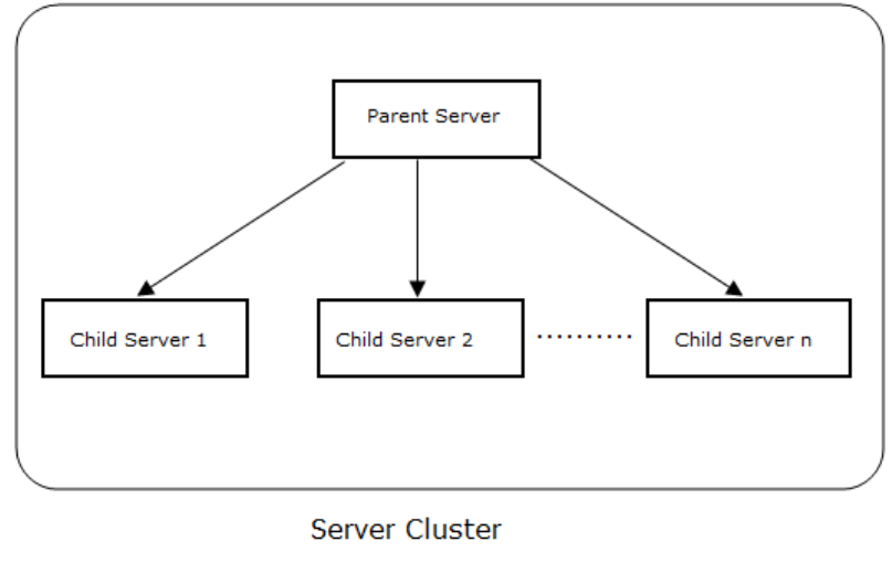
AirTight Management Console Configuration
107
Set up and Manage Server Cluster
A server cluster consists of 2 or more AirTight servers grouped together. One of these servers is the
managing server and it manages one or more AirTight servers. Thus, multiple servers can be managed
from a single server console in a server cluster.
The managing server is called the parent server and the servers that are managed from the parent
server are called the child servers. The parent server retrieves aggregated data from multiple child
servers in the cluster and displays it on AirTight Management Console along with the parent server data.
Benefits of Server Cluster
Following are the benefits of server cluster vis-à-vis SpectraGuard Manager.
• Eliminates the need for a separate product to manage multiple servers: SpectraGuard Manager
is a separate product used to manage multiple servers. With the incorporation of the server cluster
functionality in AirTight server, it is a lot easier to manage multiple servers using a single console
without the need for a separate product. The server cluster is accessible through AirTight
Management Console. Various templates and policies can be pushed to child server from the parent
server location tree.
• HTML 5 based product: AirTight Management Console is a HTML5 based console. Hence, it is
possible to access it from any device that has an HTML5 compatible browser.
• Connects with AirTight devices: AirTight Devices can connect to the AirTight Wi-Fi/AirTight WIPS
server that acts as the parent server in the server cluster.
• Ready availability of all AirTight Wi-Fi/AirTight WIPS features: All the AirTight Wi-Fi/AirTight
WIPS features are available even when a server is a part of a server cluster.
• Eliminates the need for certificate-based communication: There is no need to download a
certificate for SGM and AMC communication as the functionality to manage multiple servers in a
server cluster is provided in the same product.
• Automatic synchronization of policies: There is no need to manually synchronize policies on child
server if the child server is not available when the policies are being synchronized from a parent
server. This is done automatically when the child server comes up the next time.
AirTight Management Console User Guide
108
• Replication of policies from one server to another server in server cluster: Replication of most
policies from one server to another server in a server cluster is possible. This is regardless of whether
the policies are being copied from parent server to child server or child server to parent server.
• Aggregation of data in dashboard widgets: The number of dashboard widgets available in AirTight
Management Console is a lot higher than those available on SpectraGuard Manager. Aggregated
data from all active servers in the server cluster is seen in most of the dashboard widgets on AirTight
Management Console.
Create and Manage Server Cluster
The creation of a server cluster and management of servers in the server cluster is done using the server
command line interface (CLI). Viewing of the aggregated server cluster data and management of policies
on the child servers from the parent server is done through AirTight Management Console of parent
server.
Following are the prerequisites to create a server cluster.
• The AirTight Wi-Fi/AirTight WIPS servers that form a cluster must have the same software version
and build installed.
• A valid license must have been applied to all child servers to be added to the server cluster.
• The child server must not be a part of any other server cluster.
• If a firewall is active on the network, TCP port 22 and UDP port 1194 must be open on the firewall for
cluster formation and parent-child communication. TCP port 22 is for incoming connections to child
servers and UDP port 1194 is for incoming connections to parent server.
You can perform five cluster-related operations from the server command line interface. They are as
follows.
1. Set up a server cluster/assign parent server to a server cluster.
2. Add a child server to a server cluster.
3. Delete or remove a child server from a server cluster.
4. Delete an entire server cluster.
5. Check the status of servers in a cluster or check if a server is part of a cluster.
The servers in a server cluster are assigned IDs when they become a part of the server cluster. A parent
server is assigned 1 as ID in the cluster. As and when the child servers are added, they are assigned
sequentially incrementing IDs. The child server added first is assigned 2 as ID, the next one is assigned 3
as ID and so on.
After creating the cluster, you must mount the child servers on the parent server location tree, to be able
to view aggregated server data on the UI or push policies from parent server to child server.
The following figure illustrates the mapping of an existing location tree with child servers in a server
cluster.
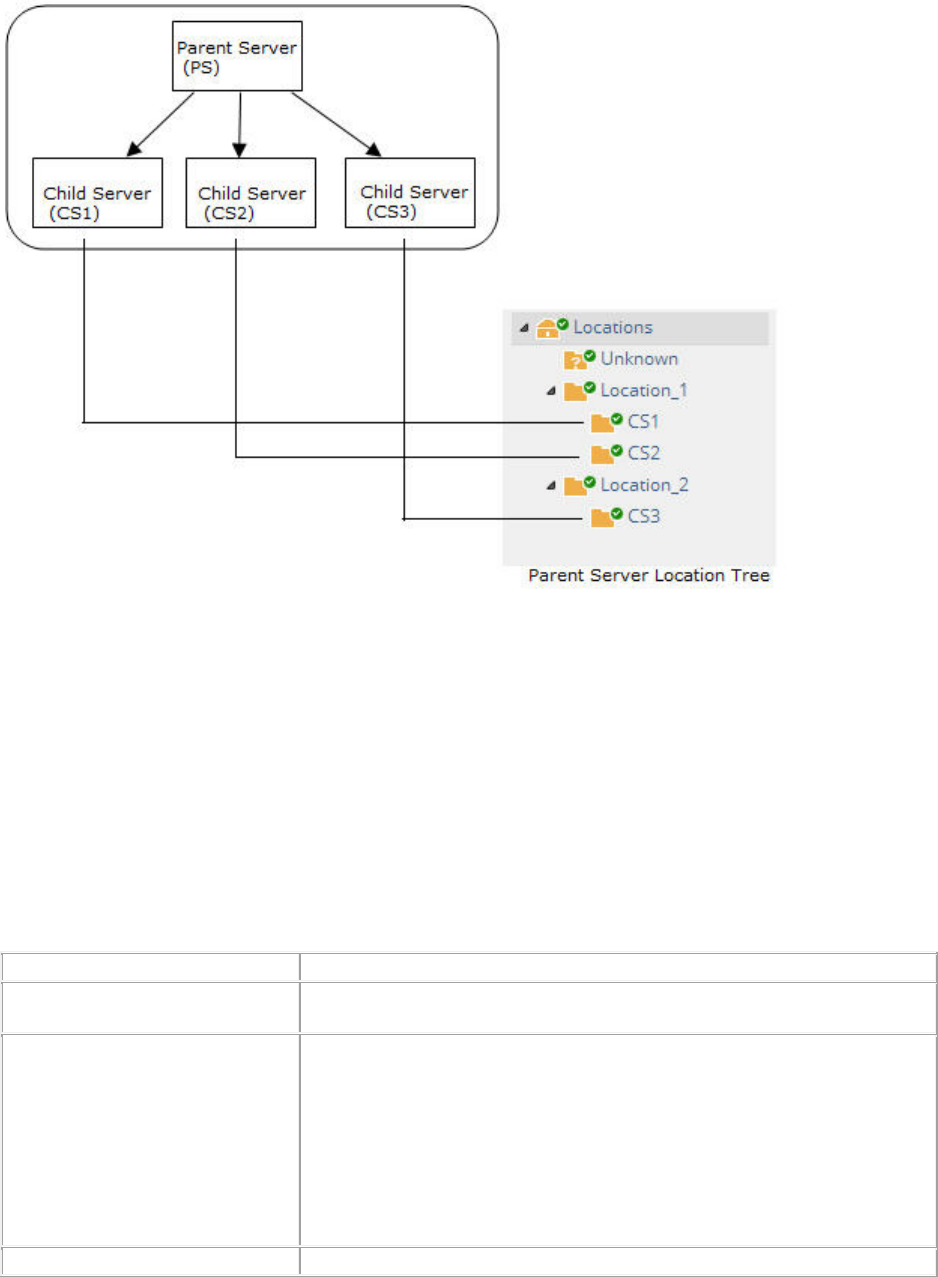
AirTight Management Console Configuration
109
Limitations of Server Cluster
Following are the limitation of a server cluster.
• A server (parent server or child server) can be a part of only one cluster at any given point.
• A child server cannot be the parent of any other server in the cluster.
Server Cluster related Commands
You can set up a cluster comprising one parent and multiple child servers through the server command
line interface.
Following is the subset of server config shell commands that are specific to creation and management of
server cluster.
Command
Description
cluster set
Sets a server as a parent server in a server cluster. This command
must be executed on the server to be set as the parent server.
cluster reset
Deletes a server cluster or a child server from a cluster. When
executed on a
parent server, the entire cluster is destroyed and all
servers in the cluster behave as standalone servers. This command
can be executed on parent server or child server When executed on a
child server, it eliminates the relationship between the child serv
er and
the parent server. The rest of the cluster remains intact.
IMPORTANT!
It is recommended to execute this command on parent
server only. It can be executed on a child server ONLY when there is
no other way to remove the child from a server cluster.
cluster add child
Adds a child to a server cluster. This command must be executed on
AirTight Management Console User Guide
110
the parent server in the server cluster.
cluster delete child
Deletes or removes a child from a server cluster. This command must
be executed on the parent server in the server cluster.
cluster show status
Displays the status of a server cluster. Using this command you can
check whether a server is in a cluster and/or the status of a server in a
cluster. This command can be executed on any server regardless of
whether it is in a server cluster or not.
Set up Server Cluster
Before setting up a server cluster, the parent or child servers can be in a standalone mode or in an HA
pair configuration with other servers. Once a server cluster is set up, the HA mode can be enabled on the
parent or child servers as and when required.
The cluster set command is used to set up a cluster. This command must be executed on the
command line interface of the server that you want to assign as the parent server in the server cluster.
You can, optionally, choose to run the server cluster setup wizard to add child servers to the server
cluster.
You can check the status of the server by executing the cluster show status command.
To set up a cluster, do the following.
1. Login to the server command line interface of the server that you want to set up as the parent server
in a server cluster. Login to the server with 'config' user credentials.
2. Execute the command cluster set on the command line. The server is set as the parent server in
the server cluster.
3. If you want to add child servers right away, enter ‘y’ when prompted to add child servers. Enter the
name for the child server, IP address of the child server and password for the config user of the child
server, to add a child server. Repeat this step to add more child servers.
Note: If a parent server or child server is in HA mode, the active server is added to the server cluster. The
standby HA server cannot be added to the server cluster. Before setting up a server cluster, a parent
server or a child server can be in standalone mode or in HA pair configuration with other servers. Once
the server cluster is set up, HA mode can be enabled at a later point on the parent server or child server,
if required.
Refer to the screenshot below for the cluster set command.
AirTight Management Console Configuration
111
Add Child Server to Server Cluster
There are two ways to add a child server to a server cluster.
1. Use the server cluster setup wizard available after executing the cluster set command. This has
been explained in the Set up Server Cluster section.
2. Execute cluster add child command. This command must be executed on the command line of
the parent server. This is explained below.
To add a child server to a server cluster using the cluster add child command, do the following.
1. Login to the server command line interface of the parent server with "config" user credentials.
2. Execute the command cluster add child on the command line. You are prompted to enter the
name for the child server to be added to the server cluster.
3. Enter a suitable name for the child server. You are prompted to enter the hostname or IP address of
the child server.
4. Enter the hostname or IP address of the child server. You are prompted to enter the "config" user
password for the child server.
5. Enter the "config" user password. If all the data entered is correct, the server having the specified
hostname/IP address is added as a child server in the server cluster.
Refer to the screenshot below for the cluster add child command.
AirTight Management Console User Guide
112
Delete Child Server from Server Cluster
A child server can be deleted from a server cluster using the cluster delete child command. When
you delete a child server from a server cluster, the link between the parent server and the child server is
broken. The rest of the server cluster continues to function as a cluster.
To delete a child server from a server cluster, do the following.
1. Login to the server command line interface of the parent server with "config" user credentials.
2. Execute the command cluster delete child on the command line. You are prompted to enter
the ID of the child server to delete from the server cluster.
3. Enter the ID of the child server to delete. You are prompted to confirm the deletion of the child server
from the server cluster.
4. Enter y to delete the child server from the server cluster. The child server is deleted from the server
cluster.
Refer to the screenshot below for the cluster delete child command.
AirTight Management Console Configuration
113
Delete Server Cluster
A server cluster can be deleted using the cluster reset command. This command must be executed
on the parent server command line to delete the entire cluster.
Note: When the cluster reset command is executed on a child server command line, it removes the
child from the cluster. This action, however, is NOT recommended unless there is no other way to remove
the child server from the cluster.
Use the cluster delete child command to delete a child server from a server cluster.
To delete a server cluster, do the following.
1. Login to the server command line interface of the parent server with "config" user credentials.
2. Execute the command cluster reset on the command line. You are prompted to confirm cluster
reset.
3. Enter y to confirm cluster reset or deletion of the server cluster. The cluster is deleted.
Refer to the screenshot below for the cluster reset command.
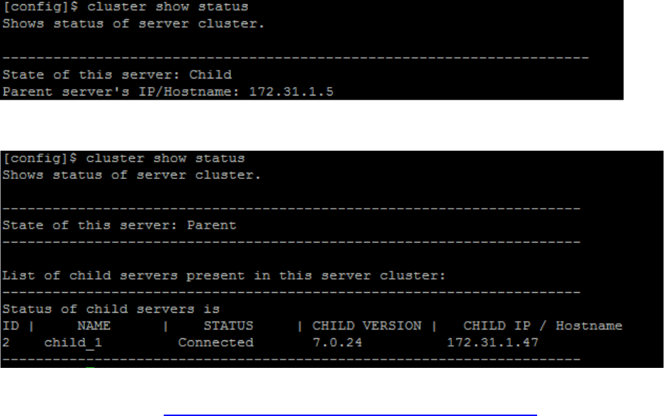
AirTight Management Console User Guide
114
Check Server Status with respect to Server Cluster
You can check if a server is part of a server cluster using the cluster show status command. When
a server is part of a server cluster, you can find out whether a server is a parent server or a child server
using the cluster show status command.
You can execute this command on a server that may or may not be in a server cluster, that is, you can
execute this command on any active server.
To check the status of a server, do the following.
1. Login to the server command line interface of the server with "config" user credentials
2. Execute the command cluster show status on the command line. The status of the server is
returned by the command.
Refer to the screenshots below for different server statuses.
The following is a screenshot of the command executed on a child server.
The following is a screenshot of the command executed on a parent server.
For instructions on mounting the child servers and managing them from AirTight Management Console of
the parent server, refer to Manage Child Servers from Parent Server in Server Cluster.
Inherit Policy from Parent Server
When a server cluster is created and a child server is mounted on a mount point, the child server retains
the policies that were previously applied to it. It does not inherit the parent server policies, by default. If
you want to apply the parent server policies to child servers, you must navigate to the individual policy
and inherit the policy from the parent server.
The following policies are location specific and they cannot be inherited.
• Intrusion Prevention Activation
• Location Time Zone
AirTight Management Console Configuration
115
• Event Activation
• Device List Locking
However, if you make changes these policies at the mount point of a child server and save these changes
to be applied recursively, the changes are pushed to all the locations present directly under the mount
point.
To inherit a policy from the parent server, do the following.
1. Select the location on the child server where you want to inherit policies from the parent server.
2. Navigate to the policy to inherit.
3. Click the Inherit Policy link. A message asking for confirmation to inherit policies appears.
4. Click Yes on the confirmation message. The parent server policy is applied to the selected location
on the child server.
Manage Child Servers from Parent Server in Server Cluster
A server cluster is a group of servers. A server cluster comprises a parent server and one or more child
servers.
A server cluster is created to manage multiple servers using a single server. This managing server is
called the parent server and the servers that are managed from the parent server are called the child
servers. The parent server retrieves aggregated data from multiple child servers in the cluster and
displays it on the AirTight Management Console along with the parent server data. You can also push
common policies onto multiple child servers from a parent server.
A server (parent server or child server) can be a part of only one cluster at any given point. A child server
cannot be the parent of any other server in the cluster.
The creation of a server cluster and management of servers in the server cluster is done using the server
command line console. Refer to the 'Set up and Manage Server Cluster' chapter for details on setting up
server cluster and to 'Server Config Shell Commands' chapter for the server cluster commands, in the
respective server installation guide .
Viewing of the aggregated server cluster data and management of policies on the child servers from the
parent server in the cluster is done through AirTight Management Console. You must be a superuser to
be able to view server cluster related options and manage server cluster data and policies through
AirTight Management Console.
Once you are done with assigning a parent server to a server cluster and adding child servers to the
server cluster, you can login to AirTight Management Console of the parent server, and then navigate to
Configuration>System>Server Cluster. Create one or more locations, if they are not already present, to
mount the child servers on the parent server location tree. If the locations have already been added,
mount the child servers on to these locations.
You can mount the child servers and also copy policies from one server to another server in the same
server cluster.
You can print a list of child servers in the server cluster. You can search for servers in the list.
Mount Child Server on Parent Server Location tree
You must mount the individual child servers on the parent server location tree to be able to manage
policies on the child server through the parent server or to view the aggregated server data for the entire
server cluster. A valid license must be applied on the child server before you can mount it on the parent
server location tree.
You cannot mount a child server on a parent server location tree in the following situations

AirTight Management Console User Guide
116
• If the parent server in an existing server cluster has been upgraded, and the parent server and child
server versions do not match. Refer to Fix Version Mismatch between Parent Server and Child
Server section to fix the version mismatch.
• If a valid license has not been applied on the child server or the license on the child server has
expired. Refer to Fix Invalid License State on Child Server section to fix the license error state.
When a child server is mounted, the parent server policies are not inherited by the child server
automatically. The child server continues to use the policies applied to it before being added to the server
cluster. Individual policies on the child server can be inherited from parent servers. For details, refer to
Inherit Policy from Parent Server
To mount a child server on the parent server, do the following.
1. Go to Configuration>System>Server Cluster.
2. Select the root location of the parent server. The child servers are displayed.
3. Click the Not Mounted link for the child server to mount. The Select Locations dialog box is
displayed.
4. Select an appropriate location to mount the child server. If the location has not been created, create
the location first.
5. Click Save to mount the child server on the selected location.
Change Mount Point of Child Server
You can change the mount point of a child server whenever you want to. You cannot change the mount
point of a child server if the license has not been applied on the child server or the license on the child
server has expired.To change the mount point of a child server on a parent server location tree, do the
following.
1. Go to Configuration>System>Server Cluster.
2. Select the root location of the parent server. The child servers are displayed.
3. Click the mount point link for the child server to mount. A message prompting you to change mount
point, unmount server appears.
4. Click Change mount point.
5. Select an appropriate location to mount the child server. If the location has not been created, create
the location first.
6. Click Save to mount the child server on the selected location.
Unmount Server from Parent Location Tree
You can unmount a child server from the parent location tree.
To unmount a child server from a parent server location tree, do the following.
1. Go to Configuration>System>Server Cluster.
2. Select the root location of the parent server. The child servers are displayed.
3. Click the mount point link for the child server to mount. A message prompting you to change mount
point, unmount server appears.
4. Click Unmount.
5. Click Save to unmount the child server from the parent location tree.
Fix Version Mismatch between Parent Server and Child Server
The parent server and the child servers in a server cluster must have the same software version numbers
installed on them to function correctly when communicating with each other. If you have upgraded the
AirTight Management Console Configuration
117
parent server and there is a version mismatch between the parent server and a mounted child
server, you are not allowed to access the child server locations from the parent server location tree. You
must fix the version mismatch to be able to access the child server locations from the parent server
location tree.
When there is a version mismatch, the Fix version mismatch link is enabled. You can click this link to fix
the version mismatch of the child server. The child server restarts after applying the upgrade.
You must download the upgrade bundle from the AirTight support website before proceeding with fixing
the version mismatch.
To fix the version mismatch between a parent server and a child server, do the following.
1. Select the root location of the parent server. The child servers are displayed.
2. Go to Configuration>System>Server Cluster. The Fix link is enabled for the child server that has a
version mismatch with the parent server.
3. Click the Fix link. The Fix version mismatch dialog box appears.
4. Click the Select File link and select the upgrade bundle file from the location at which it has been
downloaded.
5. Click Upload and Upgrade to upload the upgrade bundle and upgrade the child server with the
version mismatch.
Fix Invalid License State of Child Server
After a server cluster is created using the command line, a valid license must be applied to the child
servers. This can be done from the parent server in the cluster.
A child server is in an invalid license state when a valid license is yet to be applied on the child server or
when the license has expired.
To fix the invalid license state of a child server, do the following.
1. Select the root location of the parent server. The child servers are displayed.
2. Go to Configuration>System>Server Cluster. The Fix license link is enabled for the child server
that has an invalid license.
3. Click the Select File link and select the license file from the location at which it has been
downloaded.
4. Click Apply License to apply the license on the child server. The child server restarts on successful
application of the license on it.
Copy Policy Settings
You can copy policy settings from one server to another in a server cluster. You can copy policy settings
from child server to child server, parent server to child server, or child server to parent server. You must
be a superuser to copy policies from one server to another. Policy settings related to the following can be
copied.
• Account Suspension
• Password Policy
• Login Configuration
• Language Setting
• Audit Logs
• Vendor OUIs
• RF Propagation
• Auto Location Tagging
• Auto Deletion
• SMTP Configuration
AirTight Management Console User Guide
118
• RADIUS Configuration
• Smart Device Type
• Certificate Configuration
• LDAP Configuration
• Location Tracking Configuration
• ArcSight Integration
• Banned Device List - AP
• Banned Device List - Client
• Live RF View Settings
• AirTight Mobile Settings
• Reports Look and Feel
• HotSpot SSIDs
• Vulnerable SSIDs
• Syslog Integration
• SNMP
To copy one or more policies from one server to another, do the following.
1. Go to Configuration>System>Server Cluster.
2. Click Copy. The Copy Policies dialog box appears.
3. Select the server from which policy settings are to be copied.
4. Select the server to which the policy settings are to be copied.
5. Select the policy settings to be copied. Click >. To copy all available policy settings, click >>. If you
want to remove any policy from the list of policy settings to copy, select the policy in the right hand
box and click Remove.
6. Click OK to copy the policy settings.
Search Child Server
You can search for child servers by server name or server IP address.
To search a child server, do the following.
1. Select the root location
2. Go to Configuration>System>Server Cluster.
3. Enter the server name or the server IP address in the Quick Search box.
4. Press Enter key.
5. ">The servers with name or IP address matching the search string are displayed. The search string
could be a substring of the name or the IP address.
Print Child Server List
You can print a list of child servers in a server cluster.
To print a child server list for the root location of a parent server, do the following.
1. Go to Configuration>System>Server Cluster.
2. Select the root location of the parent server.
3. Select the columns that you want in the printed list. Click any column name to select or deselect
columns.
4. Click the print icon. The print preview of the child server list appears.
5. >Click Print to print the child server list.
AirTight Management Console Configuration
119
Manage Vendor OUIs
A list of popular vendors along with the individual MAC prefix can be seen and managed using the
Configuration>System>Vendor OUIs option. A 3-byte MAC prefix identifies the vendor for any given
802.11 device.
Add Vendor or MAC Prefix
Click Add Vendor/MAC Prefix to add a new vendor-MAC prefix pair or a new prefix to an existing vendor
name. Select an existing vendor and add a new MAC address for the vendor. Similarly, you can also add
a new vendor and one or more MAC addresses corresponding to that vendor.
Delete Vendor or MAC Prefix
Click the respective Delete hyperlink for a MAC prefix, to delete it.
Manage Device Template
An AirTight device can operate as an AP or as a sensor or both AP and sensor (one radio configured as
an AP and the other as a sensor), depending on the device model used.
W-68 is a 2x2 802.11a/b/g/n/ac access point/sensor.
C-65 is a dual radio access point/sensor with one 2x2 b/g/n radio and one 2x2 a/n/ac radio.
C-75 is a dual-band, dual-radio 3x3 802.11a/b/g/n/ac device. You can configure C-75 to function either as
an AP or as a WIPS sensor. At a given time, both radios must be configured either in the AP mode so that
the device functions as an AP, or in the sensor mode so that the device functions as a sensor.
C-75-E is a dual-band, dual-radio 3x3 802.11a/b/g/n/ac device. You can configure C-75-E to function
either as an AP or as a WIPS sensor. At a given time, both radios must be configured either in the AP
mode so that the device functions as an AP, or in the sensor mode so that the device functions as a
sensor.
SS-300-AT-O-70 is a dual-band dual-radio 3x3 802.11 b/g/n device that can be deployed outdoors. You
can configure both radios to function either in AP mode or in WIPS sensor mode at any given point in
time.
SS-300-AT-C-60 is a concurrent dual-band, dual-radio 3x3 802.11a/b/g/n device that supports multiple
modes of operation for Wi-Fi access and WIPS. You can separately configure the 2 radios, Radio 1 and
Radio 2. You can configure SS-300-AT-C-60 and to function either as AP with or without background
scanning, or as a WIPS sensor. When it functions as an AP with background scanning (dual mode), one
radio is configured as an AP and the other is configured as WIPS sensor.
SS-300-AT-C-50 is a dual-band, single radio 2x3 802.11a/b/g/n device that can operate exclusively as an
AP or as a WIPS sensor at any given point in time.
SS-300-AT-C-55 is a dual radio a/b/g/n device. Both the radios need to be configured to function either in
AP mode only or in WIPS sensor mode only. You cannot configure one radio as an AP and the other as a
sensor.
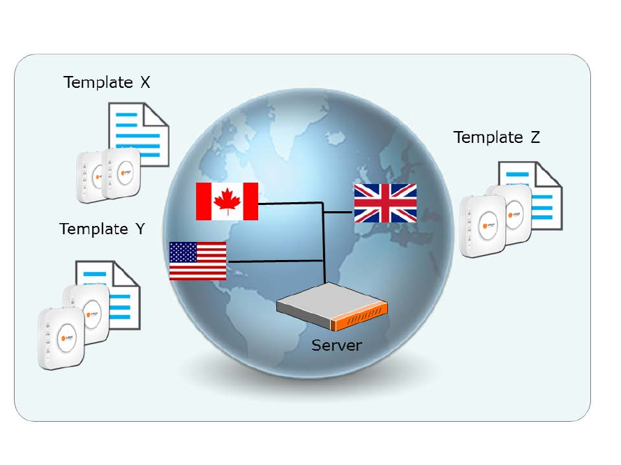
AirTight Management Console User Guide
120
SS-300-AT-C-55-E is a dual radio a/b/g/n device. Both the radios need to be configured to function either
in AP mode only or in WIPS sensor mode only. You cannot configure one radio as an AP and the other
as a sensor.
SS-300-AT-C-10 is an 802.11a/b/g/n device. SS-200-AT-01 is an 802.11a/b/g device.SS-300-AT-C-10
and SS-200-AT-01 function as WIPS sensors only. They cannot be configured to function as APs.
A device template is a set of configuration parameters such as settings for radio, channels to monitor,
VLANs to monitor, offline sensor configuration, antenna selection and port assignment. This template can
be applied to one or more AirTight devices. When you have multiple devices deployed in your
organization, configuring each individual device could be monotonous, tedious and time-consuming. A
device template is a convenient way of applying a standard set of Wi-Fi and/or WIPS settings on multiple
AirTight devices simultaneously, thereby saving time and effort, and ensuring consistency. You can have
a common device template for all the devices deployed at a location, by configuring the template as the
default device template. See the image below for a graphical representation of the use of device
templates.
Manage device templates using the Configuration>Device Templates. You need administrator
privileges to manage device templates.
Device Template
The server stores the default device configuration in a predefined template called System Template. The
System Template can be modified. Whenever an AirTight device is added or discovered, AirTight Wi-Fi
AirTight WIPS server automatically assigns the configuration settings in this template to the device. You
can edit the default configuration settings in System Template to suit your need.
AirTight Management Console Configuration
121
You can configure a template as the default template for a location. This template will be applied to any
new device tagged to that location.
When you delete a user-defined device template, System Template is applied to all the devices
associated with that template. You can manually override the template applied to an AirTight device from
the Devices > AirTight Devices tab. If you customize the settings in the template, the new settings are
applied to the AirTight devices to which this template is applied. To apply the customized settings, you
need to push the new settings on to the AirTight device.
Customize Policy/Device Template for Location
A policy is a set of rules applicable to a location. This set of rules is represented by a device template.
When you create a new location folder, it inherits the default policy or device template from the parent
location folder. Location floors inherit the default device template from their immediate parent location
folder. This means that all AirTight devices that connect to this location will use this default template.
You can define your own device template and make it the default template for a location folder. This is
called customizing the policy or device template at the selected location.
You can customize the policy or device template at the location folder level. This customization is not
available at the location floor level.
When you change the device template at a location, all the AirTight devices connecting to the location
after the change will use the newly applied device template. You can choose whether or not you want the
devices existing at the location to use the changed device template or continue using the previous default
device template. This can be done when you confirm the change in the default device template at the
location.
The Device Templates page lists the device templates that are available at all locations. For the selected
location, you must apply a device template from the available list to create the WLAN policy at that
location. This means that you must make the device template as the default template for the location. A
new AP or an existing authorized AP is compared against the applied device template to determine if it is
a rogue or misconfigured AP. Other templates could be available to be attached, but they are not part of
the WLAN policy. Therefore, they will not be used for AP classification.
To customize the policy at the selected location, do the following.
1. Click Customize at this location? link seen at the bottom of the Device Templates page. The Make
default link is enabled for user-defined device templates in the Device Templates list seen under
Configuration > Device Templates.
2. To change the default template for a location, click the Make Default link of the device template that
you want to set as the default template. A confirmation message is displayed.
3. If you want to apply the new device template to existing devices at the location click Yes. If you want
the existing devices to continue using the old default device template, click No.
Revert to Inherited Device Template
If you have defined a custom device template for a location and wish to inherit the parent device template,
do the following.
1. Click the Inherit from parent location? link seen at the bottom of the Device Templates page.
2. Click Yes on the message that asks you to confirm that you want to inherit from parent location.
Another confirmation message is displayed.
AirTight Management Console User Guide
122
3. If you want to apply the inherited device template to existing devices at the location click Yes. If you
want the existing devices to continue using the customized default device template, click No.
Add Device Template
When adding a device template, you can specify the name and description of the device template and
save the template. When the template is defined in this manner, without defining device settings and
radio settings, and applied to a device, the device functions as a WIPS sensor.
To add a new device template, do the following.
1. Click Add Device Template seen under Configuration>Device Configuration>Device Templates,
to add a new device template.
2. Specify the following values.
Field
Description
Template Name
A unique name of the device template. The name can contain a
maximum of 40 characters.
Description
A brief description of the device template. The description should
not exceed 500 characters in length.
Allow Device
Specific
Customization
Select this check box to override the settings done through device
template. Refer to Override Device Template Settings for further
details.
Operating Region
Region or country of operation of the AirTight device.
3. Specify the device password under Device Settings > Device Password on the Add Device
Template dialog box.
4. Click Save to save the device template settings.
To configure the device settings for the device template, click Device Settings on the Add Device
Template screen. Device settings are sensor-related settings. They are relevant to devices functioning as
WIPS sensors, or APs with background scanning enabled on them. Refer to Device Settings explained
below, for further details on configuring device settings for a device template.
To configure the radio settings for the device template, click Radio Settings on the Add Device
Template dialog box. Refer to Radio Settings explained below, for further details on configuring radio
settings for a device template.
Device Settings
Device Settings are further sub-divided into VLAN monitoring, Device Password, Device Access Logs,
Offline Configuration, Third Party Analytics Integration, and Channel Settings.
Each of these is explained below.
VLAN Monitoring
VLAN monitoring is essential for the wired-side connection status detection, host name detection, smart
device detection, rogue AP detection, and so on. Select Enable Additional VLAN Monitoring check box
to enable the device to monitor additional VLANs. Include all the additional VLANs to be monitored as a
comma-separated list. The VLAN used by the device to communicate with the server is always monitored
and need not be specified here. The additional VLANs to be monitored must be configured on the switch
port where the device is connected and must be DHCP enabled. A VLAN ID '0' indicates untagged VLAN
on the switch port where the device is connected, irrespective of the actual VLAN number on the switch.
AirTight Management Console Configuration
123
IMPORTANT: If a VLAN is configured with a static IP address, then configure the VLAN from the CLI.
If you want to customize the VLANs to be monitored for one or more specific devices to which a device
template is applied, you can do it using the Devices > Device Properties. In order to override the
additionally monitored VLANs, you must select the Allow Device Specific Customization check box.
Device Password
You can manage the password for the AirTight device Command Line Interface (CLI) user 'config' from
the device template. By defining a password in the device template, you can manage the password for a
group of devices without having to change it on each device separately. The password should be at least
6 characters long and it cannot contain spaces or your login ID.
You must specify the new password for the 'config' user. Confirm the new password before saving. The
new password is applied on all the devices associated with the device template.
Device Access Logs
AirTight Management Console provides you with a functionality to send the sensor access logs to the
Syslog server. This functionality is useful for audit purposes and can be enabled or disabled for a device
template. If enabled, specify Syslog server IP/Hostname to which the access logs are to be sent.
Offline Configuration
This feature provides some security coverage even when there is no connectivity between an AirTight
device and the server. The feature is relevant to an AirTight device functioning as a sensor. The sensor
provides some device classification and prevention capabilities when it is disconnected from the server.
The sensor also raises events, stores them, and pushes them back to the server on reconnection. To
enable this feature select Enable offline mode.
In the time after which, if the sensor does not receive any communication from the Server and Enable
offline Sensor mode is enabled, the sensor switches to the offline mode.(Minimum: 5 minutes; Maximum:
60 minutes; Default: 15 minutes)
There are three sub-sections under Offline Configuration
1. AirTight Device Parameters: In AirTight Device Parameters section, you can specify the following.
Number of APs to be stored: Maximum number of AP identities that the device will store in the
Offline mode (Default: 128).
Number of Clients to be stored: Maximum number of client identities that the device will store in
the Offline mode (Default: 256).
Number of events to be stored: Maximum number of raised events that the device will buffer in
the Offline mode (Default: 256). This is maintained as a cyclic buffer. That is, if the events raised
exceed this limit, the oldest events are overwritten. The buffered events are transferred to the
console when the device reconnects to the server.
Number of intrusion prevention records:Maximum number of prevention records that the sensor
will buffer in Offline mode (Default:256). This is maintained as cyclic buffer. If the records exceed
this limit, the oldest records are overwritten. The buffered records are transferred to the console
when the device reconnects to the server.
2. Device Classification Policy: Specify how the sensor should classify APs and client devices when it
is not connected to the server.
Configure the AP classification policy the following way.
• If you want to classify networked APs as rogue APs, select the Move networked APs to check
box and select the Rogue option from the drop-down list next to this check box.

AirTight Management Console User Guide
124
• If you want to classify networked APs as authorized APs, select the Move networked APs to
check box and select the Authorized option from the drop-down list next to this check box.
• If you want to classify non-networked APs as external APs, select the Move non-networked
APs to the External Folder check box.
3. Intrusion Prevention Policy: Specify the threats for which intrusion prevention is to be enabled on
the sensor when it is not connected to the server.
Select one or more check boxes for the threats that you want the sensor to prevent when in offline
mode.
The sensor can exercise intrusion prevention against the following threats: rogue APs,
uncategorized APs connected to the network, APs categorized as authorized using no security
mechanism, APs categorized as authorized using weak security mechanism, authorized client
connection to external APs, unauthorized client connection to authorized APs, uncategorized client
connection to authorized APs, authorized client participating in ad hoc network, and honey pot or
evil twin APs.
Third Party Analytics Integration
This feature enables integration of AirTight Wi-Fi/AirTight WIPS with a third-party external server, and
send the visibility analytics data to the third-party external server.
To enable integration with third-party external server, do the following.
1. Select the Enable check box.
2. Enter the third-party external server URL or IP address in Server URL.
3. Enter the key for the AirTight device to authenticate with the third-party external server in
Authorization Key.
4. Specify in Send Interval the time interval at which the AirTight device should send the client RSSI
values to the third-party external server.
Channel Settings
Select the channel for the sensor to monitor from the list of available channels. These channels will differ
according to your country of operation. Refer to the following table for the channel number, its protocol
and respective frequency.
Channel
Protocol
Frequency
(GHz)
Channel
Protocol
Frequency
(GHz)
Channel
Protocol
Frequency
(GHz)
1
b/g/n
2.412
34
a/n/ac
5.17
116
a/n/ac
5.58
2
b/g/n
2.417
36
a/n/ac
5.18
120
a/n/ac
5.6
3
b/g/n
2.422
38
a/n/ac
5.19
124
a/n/ac
5.62
4
b/g/n
2.427
40
a/n/ac
5.2
104
a/n/ac
5.52
5
b/g/n
2.432
40
a/n/ac
5.2
108
a/n/ac
5.54
6
b/g/n
2.437
42
a/n/ac
5.21
112
a/n/ac
5.56
6
b/g/n
2.437
42
a/n/ac
5.21
116
a/n/ac
5.58
7
b/g/n
2.442
44
a/n/ac
5.22
120
a/n/ac
5.6
8
b/g/n
2.447
46
a/n/ac
5.23
124
a/n/ac
5.62
9
b/g/n
2.452
48
a/n/ac
5.24
128
a/n/ac
5.64

AirTight Management Console Configuration
125
10
b/g/n
2.457
48
a/n/ac
5.24
132
a/n/ac
5.66
11
b/g/n
2.462
50
a/n/ac
5.25
136
a/n/ac
5.68
12
b/g/n
2.467
52
a/n/ac
5.26
140
a/n/ac
5.7
13
b/g/n
2.472
56
a/n/ac
5.28
149
a/n/ac
5.745
14
b/g/n
2.487
56
a/n/ac
5.28
152
a/n/ac
5.76
184
a/n/ac
4.92
58
a/n/ac
5.29
153
a/n/ac
5.765
188
a/n/ac
4.94
60
a/n/ac
5.3
153
a/n/ac
5.765
192
a/n/ac
4.96
64
a/n/ac
5.32
157
a/n/ac
5.785
196
a/n/ac
4.98
100
a/n/ac
5.5
160
a/n/ac
5.8
208
a/n/ac
5.04
104
a/n/ac
5.52
161
a/n/ac
5.805
212
a/n/ac
5.06
108
a/n/ac
5.54
161
a/n/ac
5.805
216
a/n/ac
5.08
112
a/n/ac
5.56
165
a/n/ac
5.825
Radio Settings
SS-300-AT-C-50, SS-300-AT-C-55, SS-300-AT-C-60 and SS-300-AT-O-70, C-75 and C-65 devices can
function in access point mode as well as in sensor mode.
When in AP mode, a single physical AP device can be logically split up into multiple virtual APs. You can
configure the radio settings and specify one or more Wi-Fi profiles if you configure the AirTight device to
function as an AP. Each SSID profile corresponds to and represents the configuration settings of one
virtual AP. You can configure up to 8 virtual APs on one radio.
If you want the AirTight device to function as a mesh AP, you must define and add a mesh profile to the
device template. Dual-radio AirTight device models like SS-300-AT-C-55, SS-300-AT-C-55-E, SS-300-
AT-C-60, SS-300-AT-O-70, C-75, C-75-E, and C-65 are capable of functioning as mesh APs. An AirTight
device that functions as a mesh AP cannot function in WIPS mode. Therefore, at a given point, a device
can have one or more Wi-Fi profiles attached to it or a single mesh profile attached to it. Both Wi-Fi profile
and mesh profile cannot be attached to a radio at the same time.
To operate the device in the AP mode, you must configure the radio settings, and add Wi-Fi profiles to
indicate which wired network the AP should connect to. To operate the device in the WIPS sensor mode,
all you need to do is select the device model. In every model, the available radios are configured to
function as WIPS sensors. This means that on any AirTight device model, the WIPS sensor option is
selected, by default, for all available radios.
To configure radio settings for access point mode, do the following.
1. Go to Configuration>Device Configuration>Device Templates.
2. Click Radio Settings on the Add Device Template dialog box or the Edit Device Template dialog
box, as applicable.
3. Click Define settings for model link. A drop down list of available AirTight device models appears.
4. Select the appropriate model. The details for the model appear. To configure radio settings for the
SS-300-AT-C-55-E device, select the SS-300-AT-C-55 option. To configure radio settings for the C-
75-E device, select the C-75 option.
5. Select the Operation Mode for the desired radio as Access Point.
6. Configure the radio settings.

AirTight Management Console User Guide
126
Field
Description
Frequency Band
The radio frequency band. The possible values are 2.4 GHz and 5
GHz. Default value is 2.4 GHz.
Channel Width
The channel width for the radio. Possible values are 20 MHz or 20 MHz /40
MHz. In case of a/n/ac devices, the 20/40/80 MHz option is available. The
options are enabled for 2.4 GHz and 5 GHz modes.
Operating Channel
The operating channel for the radio. By default, the AP automatically selects
the operating channel automatically (Auto). User can manually set the channel
if desired. Select Manual, to set the operating channel. Based on the location
selected in the left pane, a list of channel numbers presented for manual
channel selection, is presented. If
the manually selected channel is not present
in the country of operation selected for the device in the applied AP template,
the AP automatically reverts to Auto mode and selects a channel.
Selection In
terval
This field is visible only when the Operating Channel is set to Auto. This field
specifies the time interval, in hours, at which the channel selection happens.
You can enter any value from 1 through 48.
Channel Number
This field is visible only when the Operating Channel set to Manual. This field
specifies the operating channel number. The channel numbers seen in this box
depend on the operating region selected. If you are defining channel number
for APs in the mesh network, make sure that the channel number is the same
for all the AirTight device models functioning as mesh APs.
Background Scanning
Select this check box to enable background scanning by the AP.
IMPORTANT:
Do not enable background scanning if the radio is being used for
Voice over IP (VoIP).
Radio Advanced Settings
Custom Transmit
Power
This field enables you to control the transmission power of the AP. Select the
custom transmit power check box and
specify the transmission power of the AP
in dbm. If the custom transmit check box is deselected, the maximum allowed
transmit power allowed for the country of operation is set for the AP.
Fragmentation
Threshold
The fragmentation threshold, in bytes. Permissible value for this field is from
256 through 2346 bytes. This field is applicable to 5 GHz and 2.4 GHz modes.
RTS Threshold
The threshold for Request to Send (RTS) in bytes. It specifies the threshold for
the size of frame above which the AP shoul
d use Request to Send (RTS)/Clear
to Send (CTS) handshake for transmission. This field is applicable to 5 GHz
and 2.4 GHz modes.
Note: If the threshold is set to very small value the wireless channel is not
efficiently utilized.
This threshold is meant to be used for large frames to avoid losing them due to
collisions and causing channel resource wastage.
Beacon Interval
The time interval, in milliseconds, between AP beacon transmissions. The
value is set to 100 milliseconds. It is not editable.
DTIM P
eriod
DTIM (Delivery Traffic Indication Message) period is the time period after which
clients connected to the AP should check for buffered data waiting on the AP.
802.11n/ac Guard
Interval
A time period at the end of each OFDM symbol to allow the signal to dissipate
prior to transmitting the next signal. This prevents overlaps between two
consecutive symbols. Legacy 802.11a/b/g devices use 800ns GI. GI of 400ns
is optional for 802.11n. This field is 802.11n/ac specific. Half guard interval is
not supported for SS-300-AT-C-50 when channel width is 20 MHz.
Enable Frame
Aggregation
This field specifies the enabling or disabling of MAC protocol Data Unit (MPDU)
aggregation. This field is 802.11n/ac specific. In case of 802.11 ac radio, frame
aggregation is enabled, by default, and it cannot be disabled.

AirTight Management Console Configuration
127
Spectrum Load
Balancing Threshold
The load balancing parameter that is useful for tuning the load distribution
between 2.4 GHz and 5 GHz bands. If the difference between the number of
clients associated in 5 GHz and 2.4 GHz exceeds this threshold, band steering
to 5 GHz is not performed (as the load on 5 GHz is more) until the difference
comes below the threshold again. This field is 802.11n specific.
Antenna Settings
Selection
This field has 2 values-internal and external. If you want to work with internal
antennas, select Internal. If you want to work with external antennas, select
External. This field is 802.11n specific.
7. Click Add Wi-Fi Profile and select the relevant Wi-Fi profile for the AP, from the available list. Repeat
this step if you want to add more than one Wi-Fi profiles to the AP. Similarly, you can add a mesh profile
to the device template if you want to apply the template to AirTight devices that would function as mesh
APs.
To configure radio settings for WIPS sensor mode, do the following.
1. Click Define settings for model link. A drop down list of available AirTight device models appears.
2. Select the appropriate model. The details for the model appear. By default, all the available radios are
configured in WIPS sensor mode.
3. Click Antenna Settings. By default, Internal is selected. Select the External option if you are using
external antennas.
To remove the settings for a device model from the device template, do the following.
1. Click the respective device template link to view the details of the template.
2. Click Radio Settings.
3. Click the model name. The model configuration appears.
4. Click the Remove Model link on the top right of the model configuration.
5. Click Save to save the changes.
In case you have removed a model and want to add it back again, do the following
1. Click Add Model and select a model for which you want to define the configuration settings.
2. Define the configuration settings for the device model.
3. Click Save to save the changes.
Override Device Template Settings
A device template can be applied on to multiple AirTight devices. However, for some specific reasons,you
might want to change the transmit power, channel or additional monitored VLANs for a few APs to which
the device template has been applied. You can achieve this with the Allow Device Specific Customization
feature.
Transmit power, channel, or additional monitored VLANs are the fields that can be customized and
overridden.
You can override the device template settings at the device level by performing the following tasks.
1. Go to Configuration>Device Configuration>Device Templates.
2. Edit a device template.
3. Select the Allow Device Specific Customization check box in the device template that has been
applied to the AirTight device. You can override the radio settings parameters Channel and transmit
power, and the additional monitored VLANs.
4. Go to Devices page and select the AirTight device for which you want to override the settings.
AirTight Management Console User Guide
128
5. Change the required settings and save the changes. Refer to Customize Device Template Settings
for details on customizing these settings.
Note: You can specify the customized settings at a later point, even if you enable per device
configuration in the device template.
Edit Device Template
To edit a device template, do the following.
1. Go to Configuration>Device Configuration>Device Templates.
2. Click the link with the device template name.
3. Change one or more of the following values.
Field
Description
Template Name
A unique name of the device template. The name can
contain a maximum of 40 characters.
Description
A brief description of the device template. The description
should not exceed 500 characters in length.
Allow Device
Specific
Customization
Select this check box to override the settings done
through device template. Refer to
Override Device
Template Settings for further details.
Operating
Region
Region or country of operation of the AirTight device.
4. Click Device Settings to make changes, if any, to device settings. Refer to Device Settings for further
details.
5. Click Radio Settings to make changes, if any, to radio settings. Refer to Radio Settings for further
details.
6. Click Save to save the device template settings.
IMPORTANT: You can edit a device template at a selected location, only if you have defined the device
template at that location.
Search Device Template
You can search for device templates based on the template name.
To search for a device template, do the following
1. Go to Configuration>Device Configuration>Device Templates.
2. On the Device Templates page, type in the keyword or search string for the template name Quick
Search box on the top right corner.
3. Press Enter to filter the list of templates based on the keyword or the search string. The device
templates matching the search criteria appear in the device template listing.
Copy Device Template
You can copy a device template to another location. A copied device template is editable at the new
location.
To copy a device template from one location to another, do the following.
AirTight Management Console Configuration
129
1. Go to Configuration>Device Configuration>Device Templates.
2. Select the device template.
3. Click the Move to icon. The Select Location dialog box appears.
4. Select the location where you want to copy the device template.
5. Click OK.
Print Device Template List for Location
You can print the list of device templates for a location.
To print a list of device templates for a location, do the following.
1. Go to Configuration>Device Configuration>Device Templates.
2. Select the location for which you want to print the list of device templates.
3. Select the columns that you want in the printed list. Click any column name to select or deselect
columns.
4. Click the print icon. The print preview of the device template list appears.
5. Click Print to print the list.
Delete Device Template
You can delete a device template at a selected location, only if you have defined the device template at
that location.
Deletion of a template results in assigning default device template to the AirTight Devices associated with
this template.
You cannot delete the System Template.
To delete a device template, do the following
1. Go to Configuration>Device Configuration>Device Templates.
2. Select the location for which you want to delete the device template.
3. Select the check box for the device template you want to delete.
4. Click the delete icon. A confirmation message for deletion appears
5. Click Yes to confirm deletion of the device template.
Configure SMTP Settings
Configure the Simple Mail Transfer Protocol (SMTP) settings to send e-mails when events occur, using
the Configuration>System Settings>SMTP Configuration option. You must have administrator
privileges to configure SMTP settings.
The fields on the SMTP Configuration page and their description is as follows.
'To configure SMTP settings, do the following.
1. Go to Configuration>System Settings>SMTP Configuration.
2. Enter the details. The following table describes the fields related to SMTP.
Field
Description
SMTP Server IP Address/Hostname
IP Address or the host name of the SMTP server used by
the system for sending e
-mail alerts. The default value is
127.0.0.1:25. Following are the authentication protocols for
SMTP server

AirTight Management Console User Guide
130
• PLAIN (For sendmail 8.10 and above)
• LOGIN (For sendmail 8.10 and above)
• NTLM (Windows proprietary authentication
method)
Port
Port number of the SMTP server used by the system for
sending e-mail alerts.
Email Address in From field
source address from which e-mail alerts are sent
Enforce use of StartTLS (TLSv1)
STARTTLS is an extension to plain text communication
protocols
like SMTP that offers a way to upgrade a plain
text connection to an encrypted (TLS or SSL) connection
instead of using a separate port for encrypted
communication.
Select this check box if you want to
enforce the use of STARTTLS to send e
-mails in an
encrypted format.
Verify SMTP Server's Certificate
Select this check box to verify SMTP server's certificate
against built
-in well-known CA certificates or uploaded CA
certificate. When this check box is selected, an e
-mail is
not sent out if the certificate match fails.
Set Certificate
If an SMTP server's CA certificate is not present in the
built
-in well-known CA certificates packaged in the AirTight
appliance, the test SMTP operation fails. In such cases,
you can upload a private CA certificate of the S
MTP
server. Click this button and then click Choose to add a
private CA certificate file to be used for SMTP server
authentication. If a private certificate is uploaded only this
certificate is used for authentication; the built
-in certificates
will not be
used. If the uploaded file contains multiple
entries only the first entry is used for verification. To delete
a certificate, click Delete for the certificate and confirm
deletion. Note that the server application is restarted after
private certificate upload or delete operation.
Authentication Required
Select this check box to enable SMTP authentication.
Username
user name for SMTP server authentication, when SMTP
server authentication is enabled.
Password
password for SMTP server authentication, when SMTP
server authentication is enabled.
3. Change the server access URL, if required.
4. Click Save to save the changes
Restore SMTP Configuration Defaults
The default values for SMTP configuration are as follows.
SMTP Server IP Address/Hostname
127.0.0.1
Port
25
Email Address in From field
server@localhost.localdomain
Authentication Required
not selected
Server Access URL
https://wifi-security-server
To restore SMTP configuration defaults, do the following.
AirTight Management Console Configuration
131
1. Go to Configuration>System Settings>SMTP Configuration.
2. Click Restore Defaults to restore the default values of the SMTP configuration fields .
3. Click Save to save the changes.
Test SMTP Settings
To test SMTP settings, you can send a test email. The SMTP configuration settings are used for this mail.
The settings used for this mail are the SMTP settingsspecified by you. Make sure you have configured
SMTP correctly before testing the settings.
To test SMTP settings, do the following.
1. Go to Configuration>System Settings>SMTP Configuration.
2. To send a test e-mail, click Test SMTP Settings. An email is sent if the configuration is correct.
Copy SMTP Configuration to Another Server
You can copy the SMTP configuration from one server to another server when both servers are part of
the same server cluster. You can copy SMTP configuration from child server to child server, parent server
to child server, or child server to parent server. You must be a superuser or an administrator to copy
policies from one server to another.
To copy SMTP configuration, do the following.
1. Go to Configuration>System Settings>SMTP Configuration on the parent server.
2. Click Copy Policy. The Copy Policies dialog box appears.
3. Select the server from which the SMTP configuration is to be copied.
4. Select the server to which the SMTP configuration is to be copied.
5. Click OK to copy the SMTP configuration.
View System Status
The Configuration>System>System Status page displays information about the AirTight Wi-Fi /
AirTight WIPS server.
All the static server information is available under System Information.
The current status of the server is displayed under Server Information.
Information about backup files stored on the server is displayed under Backup Files stored on the server.
The file name,
The following table describes the static information seen on the System Status page.
Field
Description
Server ID
Specifies the unique identifier for the server appliance. If you have
installed a single server appliance, then retainthe default server ID, that
is, 1.
AirTight Device
Communication
Port
Specifies the AirTight device port number on which the AirTight
Management Console server communicates with the device.
Serial Number
Specifies the hardware serial number of the AirTight Management

AirTight Management Console User Guide
132
Console server.
Maximum
AirTight
Devices
Allowed
Specifies the maximum number of AirTight devices allowed on the
license.
Allowable
Conversions to
AP
Specifies the maximum number of AirTight devices that are allowed to
be converted to function as access point, per the current license.
Software
Version
Specifies the version number of the AirTight Management Console
software.
Software Build
Specifies the build number of the AirTight Management Console
software.
License Expiry
Date
Specifies the expiry date of the license.
IPV6 Status
Specifies whether IPV6 protocol is enabled or disabled on the server.
Start/Stop Server
Live information about the status of the system can be seen under Server Information. You can find out
if the server is running, stopped, or is in error state.
You can stop the server from this page. If the server is stopped, you can start the server.
To stop the server, click Stop Server under Server Information. To start the server, click Start Server
under Server Information. The text of the button under Server Information alternates between Stop
Server and Start Server depending on whether the server is running or has stopped.
To stop the server, do the following.
1. Go to Configuration>System>System Status.
2. Click Stop Server to stop the server.
To start the server, do the following.
1. Go to Configuration>System>System Status.
2. Click Start Server to start the server.
Upgrade Server
You can upgrade to the latest version of the AirTight Management Console, using the Configuration-
>System->Upgrade Server option. Only users in a 'super user' role can initiate a server upgrade.
Prerequisites for Upgrade
Following things need to be taken care of before upgrading to a newer version of AirTight Management
Console.
• Popup blockers on the computer from which the Console is accessed must allow popup windows
from the server.
• If there is a firewall between the computer from which the Console is accessed and the server,
TCP port 8080 of the server must be accessible from that computer.
AirTight Management Console Configuration
133
Recommended: To upgrade the server to a newer version, ensure that you access the Console using a
computer whose IP address has not been changed by Network Address Translation (NAT). If you access
the Console, using a NATed IP, upgrade will continue in the background but you cannot view the upgrade
progress messages.
Upgrade Process
1. Click Browse to select the Upgrade Bundle.
2. Click Upgrade Now to transfer the Upgrade Bundle to the server.
3. On the Confirm Upgrade dialog, click Yes to proceed with the upgrade.
4. The Uploading Upgrade Bundle message with the progress bar appears.
5. You can cancel the upgrade by clicking Cancel anytime while the Upgrade Bundle upload is in
progress.
6. After the Server Upgrade Bundle upload is complete, Server Upgrade starts automatically.
7. Close the current browser window. A new window, Server Upgrade Progress, is launched which
displays the status of the Server Upgrade process. Follow the instructions displayed on the Server
Upgrade Progress window.
8. After the server upgrade is successful, the server reboots automatically.
9. After you have read all instructions on the Server Upgrade Progress window, close all the Web
browser windows including the Server Upgrade Progress window.
10. Wait for five minutes for the server to reboot. After this, you can access the server again.
Note: You cannot abort or cancel the Server Upgrade process once the Server Upgrade Progress
window is launched. Additionally, the Server Upgrade process continues even if the Server Upgrade
Progress window is closed.
Configure Auto Deletion Settings
AirTight Management Console stores historical information about the devices visible to it and the events
related to these devices. The rate of growth of this information is dependent on the volatility of the
wireless environment at the deployed location. It is necessary to delete this information periodically, as it
becomes obsolete after some time. This is done using the Configuration->System->Auto Deletion
option.
Based on the event-related configuration done by you, the system also raises and stores a number of
events. If the configuration is such that there are significant number of events generated and stored, the
stored event data size grows significantly faster. This event data also requires regular cleanup.
Auto deletion allows you to specify values of various auto deletion parameters to control the frequency of
deletion of information. The system generates an event for tracking the action of auto deletion. This event
gives information only about device deletion. There is no event separately generated that indicates event
deletion.
The auto-deletion parameters are related to access point, client, network events. These are explained in
detail below.
Access Point Deletion Parameters: The available AP categories are Uncategorized, Rogue,
External. Authorized APs are not deleting automatically from the system. If you want to delete inactive
authorized APs, you have to delete them manually.
Note: The control for some AP categories is available in specific deployments only.
Select the AP categories for which you want to set the auto-delete duration. Specify the number of days
of inactivity after which the AP related information is to be automatically deleted for the respective
AirTight Management Console User Guide
134
category. The minimum number of days of inactivity is 1 and the maximum number of days of inactivity is
30.
Client Deletion Parameters: The available client categories are Uncategorized, Authorized, External,
Rogue, Guest.
Select the client categories for which you want to set the auto-delete duration. Select the appropriate
check box and specify the number of days of inactivity after which the client-related information is to be
automatically deleted for the respective category. The minimum number of days of inactivity is 1 and the
maximum number of days of inactivity is 30.
Network Deletion Parameters: Select the No. of days to retain exposed Networks check box and
specify the duration, in days, for which the exposed networks are to be retained on the server. The default
value is 30 days for this field. The minimum value for retention in the system is 1 day, and the maximum
value is 90 days.
Events Deletion Parameters: Specify the maximum number of security, performance and system events
that should be retained on the server.
The following table shows the event type along with the default, minimum, and maximum values.
Event Type Default
number of
events
Minimum
number of
events to
store
Maximum
number of
events to store Note
Security 50,000 20,000 80,000
The maximum number of security
events that can be retained for the SA-
350 appliance is 0.7 million.
Performance
10,000 5000 40000
The maximum number of performance
events that can be retained for the SA-
350 appliance is 0.25 million.
System 1000 500 2000
The maximum number of system
events that can be retained by can be
retained by the SA-350 is 0.05milloin.
Specify how long the events should be retained in the database: The default value is 30 days for this
field. The minimum number of days to retain events is 1 day, and the maximum number of days to retain
events is 365 days. Events older than the period specified will be purged from the database.
You can track auto-deletion of inactive APs, Clients, and events, by monitoring the special event
generated by the system. The system generates an event containing the summary of the actions
performed during the auto-deletion operation, if and only if any physical deletion of information has
actually taken place.
Copy Auto Deletion Settings to Another Server
You can copy the auto deletion settings from one server to another server when both servers are part of
the same server cluster. You can copy auto deletion settings from child server to child server, parent
server to child server, or child server to parent server. You must be a superuser or an administrator to
copy policies from one server to another.
To copy auto deletion settings, do the following.
1. Go to Configuration>System Settings>Auto Deletion on the parent server.
2. Click Copy Policy. The Copy Policies dialog box appears.
3. Select the server from which the auto deletion settings are to be copied.
AirTight Management Console Configuration
135
4. Select the server to which the auto deletion settings are to be copied.
5. Click OK to copy the auto deletion settings,
Manage Audit Log Settings
AirTight Management Console keeps a track of the user activity. The user action logs can be downloaded
from the server for viewing purpose. This is done using the Configuration>System Settings>Audit
Logs option. Only a super user has the privilege to download the user action logs.
Audit logs are also called user action logs.
Set Duration for Audit Log Download
You can specify a time duration, using the From and To fields that indicate duration between the date
from which and date up to which you want to download the user action logs. Alternatively, you can specify
a duration indicating the number of lapsed hours for which you want to download the user action logs.
You can select the type of log entries that can be downloaded. Use the For field to specify this. By
default, records of all types are included in the downloaded log file. You can sort the log on the date and
time, module, host address, user role, login name, type and status of the login attempt. Use the Ordered
by field to select the sort field. The default sorting of log entries is done on date and time.
To configure settings for user action logs to download, do the following.
1. Go to Configuration>System Settings>Audit Logs.
2. Select the type of action log to download.
3. Select the From and To date for which the user action log is to be downloaded. Alternatively, you can
select Last and specify the number of elapsed days, months or years for which you want to download
the user action logs.
4. Click Save to save the changes.
Download Audit Logs
You can download the user action logs after having set the duration and type of user action logs for the
download.
To download, do the following.
1. Go to Configuration>System Settings>Audit Logs.
2. Click Download. The user action log is downloaded as a CSV file. The contents of the log depends
on the type of action log downloaded.
Note: If the server is a parent server in a server cluster, the downloaded log is an aggregation of the
parent server and child server log data. This means that the child server logs are also included in the
parent server logs. In this case, the audit log contains an additional column 'Cluster Server'. For parent
server log entries, the value in this column in 'Cluster Parent' and for child server log entries, the value in
this column is the name of the child server itself.
Restore Default User Action Log Download Settings
1. Go to Configuration>System Settings>Audit Logs.
2. Click Restore Defaults to restore the default values.
3. Click Save to save the changes.
AirTight Management Console User Guide
136
Copy Audit Log Settings to Another Server
You can copy the audit log settings from one server to another server when both servers are part of the
same server cluster. You can copy audit log settings from child server to child server, parent server to
child server, or child server to parent server. You must be a superuser or an administrator to copy policies
from one server to another.
To copy audit log settings, do the following.
1. Go to Configuration>System Settings>Audit Logs on the parent server.
2. Click Copy Policy. The Copy Policies dialog box appears.
3. Select the server from which the audit log settings are to be copied.
4. Select the server to which the audit log settings are to be copied.
5. Click OK to copy the audit log settings.

AirTight Management Console Configuration
137
Configure Integration with Enterprise Security
Management Servers
You can configure AirTight Management Console to integrate with various enterprise security
management (ESM) servers using the Configuration->ESM Integration page.
AirTight Management Console integrates with ESM servers that collect, analyze, and display events.
AirTight Management Console sends security events related information to these servers.
AirTight Management Console integrates with SNMP, Syslog and Arcsight servers.
To configure the integration settings for SNMP, see SNMP Integration.
To configure the integration settings for Syslog, see Syslog Integration.
To configure the integration settings for Arcsight, see Arcsight Integration.
Syslog Integration
You can configure the integration settings with communication with Syslog servers for AirTight WIPS to
communicate and send log messages to Syslog servers.
If Syslog integration is enabled, the system sends messages to the configured Syslog servers. Otherwise,
Syslog integration services are shut off. Apart from events, you can also send audit logs from AirTight
WIPS to a Syslog server. You must enable integration with Syslog for AirTight WIPS to send messages
and audit logs to Syslog servers. Select the Enable Syslog Integration check box to enable integration
of AirTight Management Console/AirTight WIPS with Syslog server.
Current Status indicates the status of the Syslog server. It could be Running, Stopped or Error,
depending on the state of the Syslog server. Error status is shown if the System server is stopped, if the
hostname of an enabled syslog server cannot be resolved, or if an internal error occurs. In case of
occurrence of an internal error, you need to contact Airtight Technical Support.
Adding a Syslog Server
To add a syslog server, do the following.
1. Go to Configuration>ESM Integration>Syslog Integration.
2. Under Manage Syslog Servers, click Add Syslog Server to add Syslog server details.
3. Specify the Syslog Server IP Address or Hostname to which the events should be sent.
4. Specify the port number of the Syslog server to which the system sends events. The default port
number is 514.
5. Specify the format in which the event is sent, which is Intrusion Detection Message Exchange Format
(IDMEF) or Plain text. the default format is plain text).
6. Select the Enabled check box if you want the events and/or audit logs to be sent to this Syslog
server. It is enabled by default.
7. Select the Append BOM header check box if you want to append the byte order mark to the syslog
server entry. This is relevant in case of plain text files.
8. Select the Forward Events check box to send events to the Syslog server.
9. Select the Forward Audit Logs check box to send audit logs to the Syslog server. You can forward
audit logs in plain text format only.
10. Click OK to add the details for a new Syslog server.
AirTight Management Console User Guide
138
Edit Syslog Server
To edit syslog server settings for a syslog server, do the following.
1. Go to Configuration>ESM Integration>Syslog Integration.
2. Click the Syslog server IP address and port hyperlink in the list of Syslog servers.
3. Make the necessary changes.
4. Click OK to save the changes.
Delete a Syslog Server
You can delete a syslog server from the list of syslog servers, Once deleted from the list, the entries will
not be sent to this server.
To delete a syslog server, do the following.
1. Go to Configuration>ESM Integration>Syslog Integration.
2. Click the Delete hyperlink for the Syslog server to delete the Syslog server.
Copy Syslog Server Settings to Another Server
You can copy the Syslog server settings from one server to another server when both servers are part of
the same server cluster. You can copy syslog server settings from child server to child server, parent
server to child server, or child server to parent server. You must be a superuser or an administrator to
copy policies from one server to another.
To copy syslog server settings, do the following.
1. Go to Configuration>ESM Integration>Syslog Integration on the parent server.
2. Click Copy Policy. The Copy Policies dialog box appears.
3. Select the server from which the syslog server settings are to be copied.
4. Select the server to which the syslog server settings are to be copied.
5. Click OK to copy the syslog server settings,
Arcsight Integration
Go to Configuration>ESM Integration>Arcsight Integration to configure the integration settings for
communication with Arcsight server
AirTight Management Console integrates with ArcSight’s Enterprise Security Management (ESM)
infrastructure by sending events to the designated ArcSight server. The ArcSight server is configured to
accept syslog messages having detailed event information in ArcSight’s Common Event Format (CEF).
The system needs the IP Address or the hostname and the port on which the ArcSight server receives
events. You can add more than one Arcsight servers to receive events from AirTight Management
Console. Apart from events, you can also send audit logs from AirTight Management Console to an
Arcsight server. Refer to the following figure for a graphical representation of Arcsight integration.
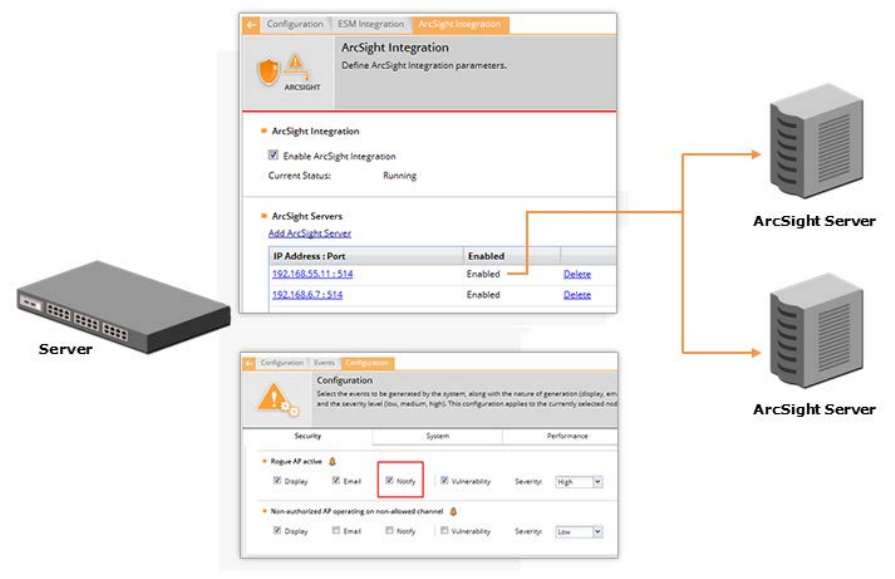
AirTight Management Console Configuration
139
Arcsight Integration
Add Arcsight Server
To add an Arcsight server, do the following.
1. Go to Configuration>ESM Integration>Arcsight Integration.
2. Click the Add Arcsight Server hyperlink.
3. Enter the Arcsight IP address, port number.
4. Select the Enabled check box if you want to enable sending CEF messages and/or audit logs
generated by AirTight Wi-Fi/AirTight WIPS to this server.
5. Select the Forward Events check box to send CEF messages to the Arcsight server.
6. Select the Forward Audit Logs check box to send audit logs to the Arcsight server.
7. Click OK to save the changes.
Edit Arcsight Server
To edit Arcsight server details, do the following.
1. Go to Configuration>ESM Integration>Arcsight Integration.
2. Click the Arcsight server IP address and port hyperlink in the list of Arcsight servers.
3. Make the necessary changes.
4. Click OK to save the changes.
Delete Arcsight Server
To edit Arcsight server details, do the following.
1. Go to Configuration>ESM Integration>Arcsight Integration.
AirTight Management Console User Guide
140
2. Click the Delete hyperlink for the Arcsight server IP address and port to delete the Arcsight server.
Once deleted from the list, the CEF messages will not be sent to this server.
Copy Arcsight Server Settings to Another Server
You can copy the Arcsight server settings from one server to another server when both servers are part
of the same server cluster. You can copy Arcsight server settings from child server to child server, parent
server to child server, or child server to parent server. You must be a superuser or an administrator to
copy policies from one server to another.
To copy Arcsight server settings, do the following.
1. Go to Configuration>ESM Integration>Arcsight Integration on the parent server.
2. Click Copy Policy. The Copy Policies dialog box appears.
3. Select the server from which the Arcsight server settings are to be copied.
4. Select the server to which the Arcsight server settings are to be copied.
5. Click OK to copy the Arcsight server settings,
SNMP Integration
Go to Configuration->ESM Integration->SNMP to configure the integration settings for communication
with SNMP server
The SNMP page enables the sending of events from AirTight Management Console, as SNMP traps to
designated SNMP trap receivers. It also enables SNMP managers to query server operating parameters
using IF-MIB, MIB-II, and Host Resources MIB.
Select Enable SNMP Integration check box to enable the integration with SNMP servers. When SNMP
integration is enabled, the system sends SNMP traps to the configured SNMP servers. Other systems
can request for information about network entities from the SNMP server. Otherwise, SNMP integration
services are shut off.
Current Status displays the current status of the SNMP server. This can be Running or Stopped or
Error, depending on the state of the SNMP server. Error status is shown if the System server is stopped
or if an internal error occurs. In case of occurrence of an internal error, you need to contact Airtight
Technical Support.
Under SNMP Settings, configure SNMP Gets or Traps.
Configure SNMP Get and SNMP Traps
Select the SNMP Gets Enabled check box to allow SNMP managers to query server-operating
parameters enlisted in IF-MIB, MIB-II, and Host Resources MIB. Deselect this check box to block queries
related to all the MIBs.
Alternatively, select SNMP v3 Parameters check box to configure SNMP v3 Get parameters, that is
Username, Authentication Password, Privacy Password, Authentication Protocol and Privacy
Protocol.(Default Username is admin; default Authentication Password is password, default Privacy
Password is password, default Authentication Protocol is MD5 and default Privacy Protocol is DES.)
Select the Show Key check box to display the password as is, without masking it.
Select the SNMP Traps Enabled check box to allow SNMP traps to be sent to configured SNMP servers.
Additionally, select the SNMP versions to be enabled and configure the relevant settings. The SNMP
agent residing on the server uses the SNMP version parameters to deliver traps to the SNMP Trap
receivers.
AirTight Management Console Configuration
141
Select SNMP v1,v2 check box to send traps to all Trap receivers accepting traps using SNMP v1, v2
protocol. You can change the Community String for the SNMP agent. All SNMP v1, v2 Trap receivers
configured, should use this community string to receive traps.(Default: public).
Select the SNMP v3 check box, to send traps to all Trap receivers accepting traps using SNMP v3
protocol. You can configure the individual parameters that is, Username, Authentication Password,
Privacy Password, Authentication Protocol and Privacy Protocol, while adding the trap
receivers/destinations. All SNMP v3 Trap receivers configured, should use these parameters to receive
traps.
Engine ID is not editable.
Default Username is admin; default Authentication Password is password, default Privacy Password is
password, default Authentication Protocol is MD5 and default Privacy Protocol is DES.
Under SNMP MIBs, you can choose to query by enabling or disabling the following SNMP MIBs
individually.
• IF MIB
• Host Resources MIB
• AirTight-MIB: If selected, the system enables the external SNMP Trap receivers to receive traps.
• MIB-II: If selected, configure the System Contact, System Name, and System Location.
(Default System Name: Wi-Fi Security Server).
Starting with version 6.7.U5, MIB-II ‘System Description (sysDescr)’ has been changed to ‘AirTight
SpectraGuard Enterprise, Version xxx’ and MIB-2 ‘System Object ID (sysOID)’ has been
changed to ‘.1.3.6.1.4.1.16901.1.1.1’.
Apart from this, with version 6.7 U5, SNMP traps are generated whenever any monitoring service
crashes, and this service is restarted successfully by the health-check daemon. Please refer to AirTight
MIB for more details.
IF MIB, Host Resources MIB, and MIB II are standard MIBs that you can download from the Internet. For
AirTight-MIB, contact AirTight Technical Support.
Add SNMP Trap Destination Server
Under SNMP Trap Destination Servers, click Add to open SNMP Configuration dialog where you can add
SNMP server details.
Destination Server (IP Address/Hostname): Specifies the IP address or the hostname of the SNMP server
to which events should be sent.
SNMP Protocol Version: Specifies the SNMP protocol version for the SNMP agent. (Default: SNMP v3)
Port Number: Specifies the port number on the receiving system to which the SNMP trap is sent. (Default:
162)
Enabled?: Specifies if the SNMP server is enabled to receive SNMP traps. (Default: Enabled)
User name: Specifies if the SNMP v3 user name. (Default:admin)>
Authentication Password: Specifies if the SNMP v3 authentication password. (Default: password)
Privacy Password: Specifies if the SNMP v3 privacy password. (Default: password)
Authentication Protocol: Specifies if the SNMP v3 authentication protocol. (Default: MD5)
Privacy Protocol: Specifies if the SNMP v3 privacy protocol. (Default: DES)
Note: You must specify a different port number if another application uses the default port. For every
combination of authentication and privacy protocol, you must specify a different user name for v3 get/trap
parameter.
Click Add to add the details for a new SNMP server.

AirTight Management Console User Guide
142
Edit SNMP Trap Destination Server
Click the SNMP trap destination server IP address and port hyperlink in the list of SNMP trap desitnation
servers. Make the necessary changes. Click OK to save the changes.
Delete SNMP Trap Destination Server
Click the Delete hyperlink for the SNMP trap destination server to delete the server. Once deleted from
the list, the events will not be sent to this server.
Copy SNMP Settings to Another Server
You can copy the SNMP settings from one server to another server when both servers are part of the
same server cluster. You can copy SNMP settings from child server to child server, parent server to child
server, or child server to parent server. You must be a superuser or an administrator to copy policies from
one server to another.
To copy SNMP settings, do the following.
1. Go to Configuration>ESM Integration>SNMP on the parent server.
2. Click Copy Policy. The Copy Policies dialog box appears.
3. Select the server from which the SNMP settings are to be copied.
4. Select the server to which the SNMP settings are to be copied.
5. Click OK to copy the SNMP settings,
Manage WLAN Integration
WLAN Integration
AirTight WIPS integrates with the underlying WLAN infrastructure. It supports integration with controller
devices from Aruba, Cisco, Meru and HP.
You must configure the integration parameters for the appropriate vendor so that AirTight WIPS is able to
provide effective wireless intrusion prevention.
On successful configuration, AirTight WIPS server fetches data from the configured controllers. This data
includes list of managed and unauthorized devices (APs and Clients) and their association and RSSI
values detected and maintained by the controllers.
To enable integration with HP MSM and provide the parameters for integration with HP MSM controller,
see Manage Integration with HP MSM Controller.
To configure the parameters for integration with Cisco WLC, see Manage Integration with Cisco WLC.
To configure the parameters for integration with Aruba Mobility Controllers, see Manage Integration with
Aruba Mobility Controllers
To configure the parameters for integration with Meru, see Manage Integration with Meru
Manage Integration with Aruba Mobility Controllers
You can configure AirTight Management Console to integrate with Aruba Mobility Controllers to fetch
wireless device details and RSSI information from the Aruba Mobility Controllers and help to manage the
WLAN infrastructure. This is done using the Configuration>WIPS>WLAN Integration>Aruba option.
AirTight Management Console Configuration
143
The Aruba WLAN architecture consists of Aruba Mobility Controllers and APs. At any time, the Aruba
Mobility Controller has all the information about the APs and devices seen/associated with these APs.
Integration with Aruba allows the system to fetch this information from Aruba Mobility Controller. Using
this information the system can automatically classify devices managed by Aruba Mobility Controllers,
and do location tracking of devices seen by Aruba APs in sensor-less or sensor and AP mixed
environment.
Select Aruba Integration Enabled check box to integrate AirTight Management Console to obtain data
from the configured mobility controllers, which are individually enabled.
When you select the Aruba Integration Enabled check box, you can configure Automatic Synchronization
Settings. The system disables a mobility controller, by default. However, automatically enables Aruba
integration when you add a new Aruba Mobility Controller.
Current Status displays the current status of the Aruba - Running, In Process or Stopped. An Error
status is shown in one of the following cases.
• One of the configured and enabled Aruba Mobility Controllers has a hostname, which cannot be
resolved.
• One of the configured and enabled Aruba Mobility Controllers is not reachable.
• System server is stopped.
• Internal error, in which case you need to contact Technical Support.
The Imported APs percentage indicates total number of APs imported from enabled Aruba mobility
controllers as a fraction of maximum allowed. The maximum allowed depends on type of appliance. The
status displayed is as of the last synchronization event. It is recommended that the utilization remains
below 80%. If the utilization exceeds 80%,the system performance may degrade and result in side effects
such as sluggish UI and sensor disconnections.
Under Automatic Synchronization Settings, select the System-Aruba Mobility Controller Synchronization
Interval.
Synchronization Interval (Minutes)specifies the interval for which the server synchronizes with the
enabled Aruba mobility controllers.
(Minimum: 15 minutes; Maximum: 60 minutes; Default: 30 minutes)
Click Restore Defaults to restore the default values for the fields on the Aruba Integration dialog.
Add Aruba Mobility Controller
You can add one or more Aruba Mobility Controllers. AirTight WIPS communicates with these controllers
and fetches wireless device details from them.
To add an Aruba Mobility Controller, do the following.
1. Go to Configuration>WIPS>WLAN Integration>Aruba.
2. Select the location for which you want to add an Aruba Mobility Controller.
3. Click Add Controller. Enter the details as described in the table below.
Field
Description
Controller (IP Address/Hostname)
IP address or hostname of the Aruba Mobility Controller with which
AirTight WIPS communicates.
Port Number
Port number of the Aruba Mobility Controller from which data is
imported.

AirTight Management Console User Guide
144
SNMP Version
SNMP version.
Select SNMPv2 if the v2 is the SNMP version.
Select SNMPv3 if the v3 is the SNMP version.
Community String
User-defined community string using which AirTight WIPS
communicates with Aruba Mobility Controller. Default value is
'public'.
Data Import
Enabled?
Select the check box to enable import of data from Aruba Mobility
Controller.
Import Managed APs
Select this check box to import managed APs from Aruba Mobility
Controller.
Import Managed Clients
Select this check box to import clients associated with APs
managed by Aruba Mobility Controller.
Import Managed Client Associations
Select this check box to import information related to AP-client
association for APs managed by the Aruba Mobility Controller.
Import Unmanaged APs
Select this check box to import APs not managed by the Aruba
Mobility Controller.
Import Unmanaged Clients
Select this check box to import clients associated with APs not
managed by Aruba Mobility Controller.
Import Unmanaged Client
Associations
Select this check box to import information related to AP-client
association for APs not managed by the Aruba Mobility Controller.
Import Signal Strength Information
Select this check box to import APs not managed by the Aruba
Mobility Controller. Note: Location Tracking result
s may vary
depending on the Aruba AP models used in the network.
4. Click Save to save the changes.
Edit Aruba Mobility Controller settings
You can edit Aruba mobility Controller settings.
To edit Aruba Mobility Controller settings, do the following.
1. Go to Configuration>WIPS>WLAN Integration>Aruba.
2. Select the location for which you want to edit the Aruba Mobility Controller.
3. Select the check box for the Aruba Mobility Controller to edit.
4. Click the edit icon.
5. Make the required changes.
6. Click Save to save the changes.
Delete Aruba Mobility Controller
You can delete the details of an Aruba Mobility Controller. Once deleted, AirTight WIPS will not retrieve
any details from this Aruba Mobility Controller.
To delete Aruba Mobility Controller details, do the following.
1. Go to Configuration>WIPS>WLAN Integration>Aruba.
2. Select the location for which you want to delete the Aruba Mobility Controller list.
3. Select the check box for the Aruba Mobility Controller to delete.
4. Click the delete icon to delete details of the Aruba mobility controller.
AirTight Management Console Configuration
145
Print Aruba Mobility Controller List for Location
You can print a list of Aruba Mobility Controllers for a location.
To print a list of Aruba Mobility Controllers, do the following.
5. Go to Configuration>WIPS>WLAN Integration>Aruba.
6. Select the location for which you want to print the Aruba Mobility Controller list.
7. Click the print icon to print the list of Aruba Mobility Controllers. A print preview appears.
8. Click Print to print the list.
Configure Integration with HP MSM Controller
The HP MSM Controller manages a collection of thin APs. Configure integration with HP MSM Controller
using the Configuration>WIPS>WLAN Integration>HP MSM Controller option.
The HP MSM architecture consists of MSM Controllers and the APs that are managed by these
controllers. Integration with HP MSM Controller allows the AirTight WIPS server to fetch information about
Synchronized APs. Using this information, the AirTight WIPS server automatically classifies these
devices.
Select the HP MSM Integration Enabled check box to enable integration for all configured controllers.
Enabling the MSM Controller integration allows the system to obtain data from the configured controllers.
Enabling / Disabling individual controllers is also possible.
The Current Status displays Running if integration is enabled, and it displays Stopped if controller
integration is switched off.
The Status for each individual controller displays Error if
• One of the configured and enabled MSM Controllers has a hostname which cannot be resolved
• One of the configured and enabled MSM Controllers is not reachable
• System server is stopped
• Internal error (Contact Technical Support)
Configure Automatic Synchronization Settings
Under Automatic Synchronization Settings, select the Synchronization Interval. The
Synchronization Interval specifies the interval after which the server synchronizes with the HP MSM
Controller. The default value is 15 minutes. A maximum value that can be specified here is 60 minutes.
Manage Client Certificate
When the MSM Controller is configured to communicate with client programs using Secure HTTP and
Client Authentication, a client certificate is uploaded into the MSM Controller’s Trusted CA Certificate
Store. Click Download Client Certificate to download a pre-generated client certificate for AirTight
Management Console.
Note: To customize the client certificate refer to the CLI commands: get msmcontroller cert, get
msmcontroller certreq, and set msmcontroller cert as described in Config Shell Commands in the
Installation guide.
Add HP MSM Controller
You can add multiple HP MSM controllers to integrate with AirTight WIPS.
To add a HP MSM controller, do the following.

AirTight Management Console User Guide
146
1. Go to Configuration>WIPS>WLAN Integration>HP MSM Controller.
1 Select the location for which you want to add a HP MSM Controller.
2. Click Add Controller. The MSM Controller dialog box appears.
3. Configure the fields in the MSM Controller dialog box as described in the table below.
Field
Description
Controller Name
Controller Name or IP address of the HP MSM Controller with which
AirTight WIPS communicates.
Port Number
Port number of the HP MSM Controller from which data is imported.
Authentication
Type of authentication for MSM Controller.
Select the Secure HTTP (SSL/TLS) option if the MSM Controller is
configured to use HTTPS for authentication.
Select t
he HTTP Authentication if HP MSM Controller requires HTTP
authentication.
Username
User name for HP MSM Controller HTTP authentication. This field appears
only when authentication is selected.
Password
Password for HP MSM Controller HTTP authentication. This field appears
only when authentication is selected.
Using Client Certificate
Select this check box if client certificate is used. This field is valid only if
secure HTTP authentication is selected.
Note:
If the MSM Controller is setup to use client authentication, ensure
that the AirTight WIPS client certificate is uploaded into the HP MSM
Controller's trusted CA certificate store.
Data import enabled
Select this check box to enable the import of data from HP MSM controller.
4. Click Save to save the details for the new HP MSM Controller.
Check Connectivity with HP MSM Controller
Once you have added the details for HP MSM Controllers, you can test connectivity of AirTight WIPS with
each of these Controllers. Apart from this, you can check this connectivity at any time.
To test connectivity with an HP MSM controller, do the following.
1. Go to Configuration>WIPS>WLAN Integration>HP MSM Controller.
2. Select the location for which you have added HP MSM Controller and want to test the connectivity.
3. Select the check box for the Controller for which you want to test the connectivity.
4. Click the Test Connectivity icon. The System will return Pass status if the HP MSM Controller has
been correctly configured. The System will return Fail status if the HP MSM Controller has been not
been correctly configured.
Edit HP MSM Controller
To edit a HP MSM controller, do the following.
1. Go to Configuration>WIPS>WLAN Integration>HP MSM Controller.
2. Select the location for which you want to edit the HP MSM Controller details.
3. Select the check box for the Controller to edit.
4. Click the edit icon in the toolbar. The MSM Controller dialog box appears.
5. Change the fields in the MSM Controller dialog box as described in the table below.
Field
Description
Controller Name
Controller Name or IP address of the HP MSM Controller with

AirTight Management Console Configuration
147
which AirTight WIPS communicates.
Port Number
Port number of the HP MSM Controller from which data is
imported.
Authentication
Type of authentication for MSM Controller.
Select the Secure HTTP (SSL/TLS) option if the MSM Controller
is configured to use HTTPS for authentication.
Select the HTTP Authentication if HP MSM Controller requires
HTTP authentication.
Username
User name for HP MSM Controller HTTP authentication. This field
appears only when authentication is selected.
Password
Password for HP MSM Controller HTTP authentication. This field
appears only when authentication is selected.
Using Client Certificate
Select this check box if client certificate is used. This field is valid
only if secure HTTP authentication is selected.
Note: If the MSM Controller is setup to use client authentication,
ensure that the AirTight WIPS client certificate is uploaded into
the HP MSM Controller's trusted CA certificate store.
Data import enabled
Select this check box to enable the import of data from HP MSM
controller.
6. Click Save to save the changes.
Print HP MSM Controller List for Location
You can print a list of HP MSM Controllers for a location.
1. To print the HP MSM controller, do the following.
2. Go to Configuration>WIPS>WLAN Integration>HP MSM Controller.
3. Select the location for which you want to print the list of HP MSM controllers.
4. Click the print icon in the toolbar. The print preview of the list of HP MSM controllers appears.
5. Click Print to print the list of HP MSM Controllers for the selected location.
Delete HP MSM Controller
To delete the HP MSM controller, do the following.
1. Go to Configuration>WIPS>WLAN Integration>HP MSM Controller.
2. Select the location for which you want to delete the list of HP MSM controllers.
3. Select the check box for the HP MSM Controller you want to delete.
4. Click the delete icon in the toolbar. A message asking to confirm deletion appears.
5. Click Yes to confirm deletion.
Enable Integration with HP MSM Controllers
To enable an HP MSM Controller, do the following.
1. Go to Configuration>WIPS>WLAN Integration>HP MSM Controller.
2. Select the location for which you want to enable integration with HP MSM Controllers.
3. Select the HP MSM Integration Enabled check box to enable integration with HP MSM Controllers.
4. Click Save to save the changes.
AirTight Management Console User Guide
148
Disable Integration with HP MSM Controllers
To disable integration with HP MSM Controller, do the following.
1. Go to Configuration>WIPS>WLAN Integration>HP MSM Controller.
2. Select the location for which you want to disable integration with the HP MSM Controllers.
3. Select the HP MSM Integration Enabled check box to enable integration with HP MSM
Controllers.
4. Click Save to save the changes.
Manage Integration with Cisco WLC
Configure integration with Cisco wireless LAN Controller (WLC) using the Configuration>WIPS>WLAN
Integration>Cisco WLC Integration option.
The WLC governs a collection of thin AP. LWAPP defines the network protocol between the APs and
WLC. The advantages of this solution are as follows.
• Increased scalability
• Simplified, centralized management
• Zero-touch AP deployment and configuration
• Network-wide monitoring
The Cisco Unified WLAN architecture consists of Wireless LAN Controllers (WLC) and APs. The APs are
managed using Light Weight Access Point Protocol (LWAPP). At any time, the WLC has all the
information about the APs and devices seen or associated with these APs.
Integration with Cisco WLC allows the system to fetch this information from WLC. Using this information
the system can automatically classify devices managed by WLC and do location tracking of devices seen
by LWAPP APs in sensor-less or sensor and AP mixed environment.
Important!: Currently, the system supports the following managed APs: Cisco Aironet 1000 Series, Cisco
Aironet 1100 Series, Cisco Aironet 1130 Series, Cisco Aironet 1140 Series, Cisco Aironet 1200 Series,
Cisco Aironet 1230 AG Series, Cisco Aironet 1240 AG Series, Cisco Aironet 1250 Series, and Cisco
Aironet 1300 Series. The system supports WLC version 4.2.x to 8.0.
Select the WLC Integration enabled check box to enable AirTight Management Console to obtain data
from the configured WLCs, which are individually enabled.
If you select WLC Integration Enabled check box, you can configure Automatic Synchronization
Settings. AirTight WIPS disables WLC by default. However, automatically enables WLC Integration when
you add a new WLC.
Current Status displays the Current Status of the WLC that is whether it is Running or Stopped.
An Error status is shown in one of the following cases.
• One of the configured and enabled WLCs has a hostname, which cannot be resolved.
• One of the configured and enabled WLCs is not reachable.
• System server is stopped.
• Internal error, in which case you need to contact Technical Support.
The Imported APs percentage indicates total number of APs imported from WLC(s) as a fraction of
maximum allowed. The maximum allowed depends on type of appliance. The status displayed is as of the
last synchronization event. It is recommended that the utilization remains below 80%. If the utilization
AirTight Management Console Configuration
149
exceeds 80%,the system performance may degrade and result in side effects such as sluggish UI and
sensor disconnections.
Under Automatic Synchronization Settings, specify the AirTight Management Console-WLC
Synchronization Interval, in minutes.
(Minimum: 15 minutes; Maximum: 60 minutes; Default: 30 minutes)
If the customer has some Lightweight Access Points (LAPs) whose type (like ap1030, ap1130) is not
supported by AirTight Management Console, then these LAPs can be supported by importing the WLC
configuration bundle received from the AirTight Support on request. After the bundle is received, select
Use Custom WLC Configuration and click Upload Custom Configuration File. The Import Custom WLC
Configuration File dialog appears. Choose the file and upload it. The custom WLC configuration file from
this bundle is used for all future WLC synchronization. The bundle is imported as .tgz.
If the file is not imported for some reason or if the file is corrupted, an error message is displayed.
Note: Only the superuser is allowed to import WLC configuration file. All other users, including the
administrator has only the viewing rights.
Add WLAN Controller
Under Wireless LAN Controllers, click Add Controller to open WLAN Controller dialog where you can
add WLC details.
You can add multiple WLCs to integrate with AirTight WIPS.
To add a Cisco WLC, do the following.
1. Go to Configuration>WIPS>WLAN Integration>Cisco WLC
1 Select the location for which you want to add a WLC
2. Click Add Controller. The Wireless LAN Controller dialog box appears.
3. Configure the fields in the Wireless LAN Controller dialog box as described in the table below.
Field
Description
Controller (IP Address/Hostname)
IP address or hostname of the Cisco WLC with which AirTight
WIPS communicates.
Port Number
Port number of the WLC from which data is imported.
SNMP Version
SNMP version.
Select SNMPv2 if the v2 is the SNMP version.
Select SNMPv3 if the v3 is the SNMP version.
Community String
User-defined community string using which AirTight WIPS
communicates with WLC. Default value is 'public'.
Data Import Enabled?
Select the check box to enable import of data from WLC.
Import Managed APs
Select this check box to import managed APs from WLC.
Import Managed Clients
Select this check box to import clients associated with APs
managed by WLC.
Import Signal Strength Information
Select this check box to import signal strength information of
managed devices from WLC.
4. Click Save to add the details for a new WLC.
Edit WLAN Controller
AirTight Management Console User Guide
150
To edit the details of a WLC, do the following.
1. Go to Configuration>WIPS>WLAN Integration>Cisco WLC
2. Select the location for which you want to edit a WLC
3. Select the check box for the WLC to edit.
4. Click the edit icon.
5. Make the required changes.
6. Click Save to save the changes.
Delete WLAN Controller
1. Go to Configuration>WIPS>WLAN Integration>Cisco WLC
2. Select the location for which you want to delete a WLC
3. Select the check box for the WLC to delete.
4. Click the delete icon. A delete confimation message is seen.
5. Click Yes on the confirmation message to delete WLAN Controller.
Test connectivity with Cisco WLC
You can test the connectivity of the Cisco WLC configured under Cisco WLC.
1. Go to Configuration>WIPS>WLAN Integration>Cisco WLC.
2 Select the location.
3 Select the check box for the WLC for which you want to check the connectivity.
4 Click the Test icon to confirm the validity of IP Address/Hostname, SNMP settings, and version
compatibility of the selected WLC.
Print WLC list for Location
You can print the list of WLC configured for a location.
To print the WLC list, do the following.
1. Go to Configuration>WIPS>WLAN Integration>Cisco WLC.
2. Select the location for which you want to print the WLC list.
3. Click the print icon to print the list of WLCs. A print preview appears.
4. Click Print to print the WLC list.
Set WLC Configuration File
You can configure whether the default WLC configuration file should be used or a custom WLC
configuration file should be used by AirTight WIPS.
The custom WLC configuration file is provided by AirTight support.
To configure the WLC configuration file to be used, do the following.
1. Go to Configuration>WIPS>WLAN Integration>Cisco WLC.
2. Select the location.
3. Select the Use default WLC configuration option to use the default WLC configuration file.
4. Select the Use custom WLC configuration option to use a custom WLC configuration file. Click
Upload custom configuration file and choose the custom WLC configuration file provided by AirTight
support.
AirTight Management Console Configuration
151
Manage Integration with Meru
Meru Integration enables the system to use Virtual Cell and Virtual Port Architecture for reporting
accurate AP inventory. System also detects the physical APs to which the Clients are associated. This
helps the user for accurate location tracking and to protect against advanced threats.
Configure integration with Meru using the Configuration>WIPS>WLAN Integration>Meru option.
To activate integration with Meru, do the following.
1. Go to Configuration>WIPS>WLAN Integration>Meru.
2. Select the Enable Virtual Cell and Virtual Port Support check box to activate support for Meru
Virtual Cell and Virtual Port architecture.
3. Click Save. On saving the server restarts to activate the changes.

AirTight Management Console User Guide
152
Manage AirTight Mobile Clients
AirTight Mobile provides wireless security for mobile computers.
It protects the sensitive data on laptops, computers and smart phones, and protects against wireless
attacks.
AirTight Mobile integrates with AirTight Management Console. With this integration, it is possible to
centrally manage AirTight Mobile users. You can create client groups and apply common policies to them.
You can also have a centralized risk level management of the mobile computers and centralized audit of
wireless activity on mobile computers.
To configure the settings for AirTight Mobile - AirTight Management Console communication, see
Settings.
To manage AirTight Mobile groups through AirTight Management Console, see AirTight Mobile groups.
To manage AirTight Mobile clients through AirTight Management Console, see Manage AirTight Mobile
Clients.
AirTight Mobile Settings
Define the AirTight Mobile configuration parameters using the Configuration-> AirTight Mobile-
>Settings option.
A shared key is used for authentication of clients running AirTight Mobile. AirTight Mobile cannot connect
to the server for synchronization without a shared key. This shared key should be distributed to all the
users of wireless clients running AirTight Mobile.
Change Shared Key
Under Shared Key Authentication, select Change Shared Key check box to change the existing shared
key.
Enter the Shared Key manually or click Generate Random Key to automatically generate a shared key
of up to 10 alphanumeric characters. AirTight Mobile clients connect to AirTight Management Console
with this key.
IMPORTANT: You need to be very careful about changing the Shared Key if it has already been
circulated to existing AirTight Mobile Clients. This is because, if you change the Shared Key, existing
AirTight Mobile users will not be able to connect to the server unless they reactivate their AirTight Mobile
Clients using the new Shared Key.
Configure Activity Parameters
Under Activity Parameters, specify the following.
Keep-alive Interval: Indicates the duration at which AirTight Mobile sends a heartbeat to AirTight
Management Console indicating that it is active.
(Minimum: 1 minute; Maximum: 30 minutes; Default: 2 minutes)
Keep-alive Heartbeat: Indicates the number of consecutive heartbeat packets missed by AirTight
Management Console before it declares that AirTight Mobile instance as inactive.
(Minimum: 2 heartbeats; Maximum: 10 heartbeats; Default: 5 heartbeats)
Synchronization Interval: Defines the minimum period at which AirTight Mobile synchronizes with the
server.
(Minimum: 30 minutes; Maximum: 300 minutes; Default: 60 minutes)

AirTight Management Console Configuration
153
License File Path: The path to the AirTight Mobile license file. You can change the path by clicking
Choose file and choosing a new path.
Manage AirTight Mobile Clients
You can centrally manage the AirTight Mobile clients using the Configuration>AirTight Mobile-
>Manage AirTight Mobile clients option. You can change the group for AirTight Mobile clients, fetch a
report from an active AirTight Mobile client, schedule a report on an inactive AirTight Mobile client, delete
AirTight Mobile clients. To do these operations, you can filter or search AirTight Mobile clients on the
client name or the client group.
The following table describes the information about AirTight Mobile clients presented on the Manage
AirTight Mobile Clients page.
Field
Description
AirTight Mobile Status
Indicates whether the AirTight Mobile client is active or inactive.
AirTight Mobile Risk Level Icon
Identifies the AirTight Mobile risk level – High, Medium, or Low.
AirTight Mobile Report Status
Indicates one of the following -Report available, Report not available,
or Report Scheduled.
Name
Specifies the first name and last name and / or host name of the
client.
Wireless MAC
Specifies the first detected wireless MAC address of the Client in case
of multiple wireless interfaces.
Wired MAC
Specifies the first detected wired MAC address of the Client in case of
multiple wired interfaces.
Version
Specifies the build and version number of the software loaded in the
Client.
Group
Specifies the group name as defined through Group Management.
The asterisk before a group name indicates that the group has been
manually changed for the client, from a AirTight Mobile reported group
to manually created group.
AirTight Mobile Reported
Group
Specifies the AirTight Mobile reported group to which the Client
belongs. , “AirTight Mobile Reported Group” column displays
information about the domain name and group name (OU Hierarchy)
reported by AirTight Mobile Client as “<Domain Name>/<Group Name
(OU Hierarchy)>”.
Email
Specifies the e-mail address of the AirTight Mobile user using the
AirTight Mobile client.
Last S
ynch
Specifies the time when the AirTight Mobile Client last synchronized
with the system.
Activation
Specifies the date and time when the AirTight Mobile Client was
activated.
Last Available Report
Specifies the time when a report was last generated for the selected
AirTight Mobile Client.
If the server is a parent server in a server cluster, the AirTight Mobile client listing is an aggregation of
AirTight Mobile clients on the parent server and child servers in the server cluster . This means that the
Airtight Mobile clients on the child servers are also included in the parent server AirTight Mobile listing.
AirTight Management Console User Guide
154
The AirTight Management Console servers with version 6.7, 6.7 Update 1, 6.7 Update 2, 6.7 Update 3
and 6.7 Update 4 are compatible with AirTight Mobile versions 2.5 and 2.7, 3.0 and 3.1.
Fetch Report from AirTight Mobile Client
This option is available for an active AirTight Mobile Client.
To fetch report from an active AirTight Mobile client, do the following.
1. Go to Configuration>AirTight Mobile>Manage AirTight Mobile Clients.
2. Select an active AirTight Mobile client.
3. Click the Fetch Report icon to fetch a fresh report from the AirTight Mobile Client.
Schedule Report on AirTight Mobile Client
This option is available for an inactive AirTight Mobile client.
Do the following to schedule a report on an inactive AirTight Mobile client.
1. Go to Configuration>AirTight Mobile>Manage AirTight Mobile Clients.
2. Select the client on which you want to schedule a report.
3. Click the Schedule Report icon to schedule a report for the selected AirTight Mobile Client. A fresh
report is generated for the client when it becomes active.
View available AirTight Mobile report in AirTight Management Console
This option is available for a AirTight Mobile Client for which a report has been fetched earlier. This option
enables you to view various reports generated earlier for the selected AirTight Mobile Client. Each time
the system generates a AirTight Mobile report, it updates the Last Available Report column on the
Manage AirTight Mobile Clients screen.
Do the following to view an available report.
1. Go to Configuration>AirTight Mobile>Manage AirTight Mobile Clients.
2. Select the client for which you want to view the already available report.
3. Click the View Available Report icon to view the available report once again.
Change AirTight Mobile Group
You can change the group to which the client belongs. The new group can be any group except the group
currently associated with the selected client. After the clients group changes, the policy applicable to this
client is applied to the AirTight Mobile client.
Do the following to change the existing client group.
1. Go to Configuration>AirTight Mobile>Manage AirTight Mobile Clients.
2. Select one or more clients for which you want to change the group.
3. Click the Change AirTight Mobile Group icon and select the new group from the list of groups
displayed.
Delete AirTight Mobile Client
Do the following to delete an AirTight Mobile client.
AirTight Management Console Configuration
155
1. Go to Configuration>AirTight Mobile>Manage AirTight Mobile Clients.
2. Select one or more clients to delete.
3. Click the Delete AirTight Mobile Client icon to delete an Airtight Mobile client. Confirm the deletion by
clicking OK.
Filter/Search AirTight Mobile Clients
You can filter the AirTight Mobile Client List based on the Name, Group, or AirTight Mobile Reported
Group.
Do the following to filter AirTight Mobile Client list.
1. Go to Configuration>AirTight Mobile>Manage AirTight Mobile Clients.
2. Enter the search/filter criteria in the Quick Search box. You may enter the name, the group or the
AirTight Mobile group to filter the AirTight Mobile client data.
3. Press the Enter key. The AirTight Mobile clients matching the search/filter criteria are seen in the list.
You can also select the columns to be seen on the Manage AirTight Mobile Clients page. The available
columns are
• AirTight Mobile Status
• AirTight Mobile Risk Level
• AirTight Mobile Report Status
• Last Available Report
• Name
• Wired MAC
• Wireless MAC
• Version
• Group
• AirTight Mobile Reported Group
• Email
• Last Synch
• Activation
Do the following to select the columns to be made visible on the Manage AirTight Mobile Clients page.
1. Go to Configuration>AirTight Mobile>Manage AirTight Mobile Clients.
2. Click a column heading. A down arrow appears at the right of this column.
3. Click the down arrow.
4. Select Columns option from the menu that appears.
5. Select the check boxes for the individual columns that are to be made visible on the Manage AirTight
Mobile Clients page.
Print List of AirTight Mobile Clients for Location
You can print a list of AirTight Mobile clients for a location.
To print the AirTight Mobile clients' list, do the following.
1. Go to Configuration>AirTight Mobile>Manage AirTight Mobile Clients.
2. Select the location for which you want to print the existing list of AirTight Mobile clients.
3. Select the columns that you want in the printed list. Click any column name to select or deselect
columns.
4. Click the Print icon. A print preview of the list appears.
5. Click Print seen on top of the list.
AirTight Management Console User Guide
156
6. Select the printer.
7. Click Print.
Enable Pagination for AirTight Mobile Client Listing and Set Page Size
By default, the AirTight Mobile client listing is presented in a grid. You can scroll down to the last AirTight
Mobile row without having to browse across pages. A paginated view is also available if you want to view
a page-wise list of AirTight Mobile clients. You can enable pagination for the AirTight Mobile clients that
are visible to you and configure the number of rows on each page.
To enable pagination, do the following.
1. Go to Configuration>AirTight Mobile>Manage AirTight Mobile Clients.
2. Click the icon seen on the right side of the tool bar. A message to confirm pagination for all
grids/listings on the UI appears.
3. Click OK. The pagination for AirTight Mobile client listing is enabled. The pagination for all other
grids such as AirTight devices, clients, networks, APs and events is enabled as well. Note that this
setting is restricted to your login only and is not applicable to other users.
To set the page size, do the following.
1. Go to Configuration>AirTight Mobile>Manage AirTight Mobile Clients.
2. On the tool bar, click the down arrow next to the number of rows displayed to the left of the icon.
The options First Page and Set page size appear.
3. Click Set Page Size and enter the number of rows to be visible on each page.
4. Click OK.
You can browse through the paginated AirTight Mobile clients listing by clicking the (next page) and
(previous page) icons. To go to the first page, click the down arrow next to the number of rows on the
page and select the First page option.
Disable Pagination for AirTight Mobile Client Listing
If you have enabled pagination and want to disable it, you can restore the default view of having a
complete listing of all AirTight Mobile clients on a single page.
To disable pagination, do the following.
1. Go to Configuration>AirTight Mobile>Manage AirTight Mobile Clients.
2. Click the icon seen on the right side of the tool bar. A message to confirm disabling of pagination
for all grids/listings on the UI appears.
3. Click OK. The pagination for AirTight Mobile client listing is disabled. The pagination for all other
grids such as AirTight devices, clients, networks, APs and events is disabled as well. Note that this
setting is restricted to your login only and is not applicable to other users.
You can set up and manage groups for wireless clients running AirTight Mobile, using the
Configuration>AirTight Mobile>AirTight Mobile Groups page.
Group Management allows the user to manage AirTight Mobile policy groups. AirTight Mobile groups can
be created manually. AirTight Management Console can also be configured to create AirTight Mobile
groups automatically from the users’ domain and logged in group as reported by AirTight Mobile.
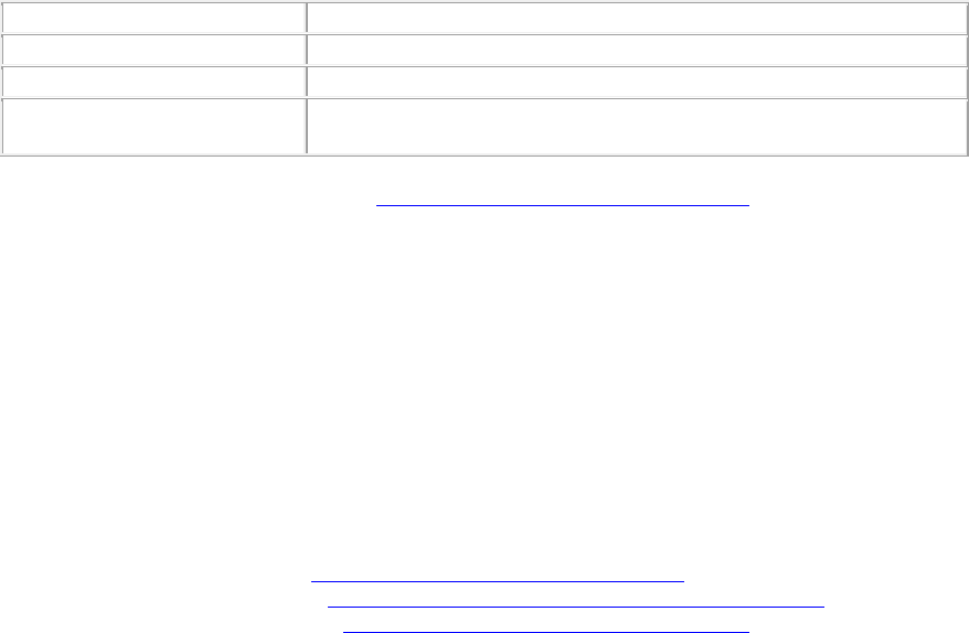
AirTight Management Console Configuration
157
Each group can have an AirTight Mobile policy attached to it. The AirTight Mobile policies are created
using an AirTight Mobile Client. The policy configuration is then imported in AirTight Management
Console in XML format.
If no policy is attached to a group, the server does not push any policy to the Clients in that group. The
Clients retain the previous policy. When you do not attach a policy or you detach a policy from an AirTight
Mobile group, AirTight Management Console does not send the Activity Parameter information such as
Keep-alive Interval, Keep-alive Timeout, and Synchronization Interval to the Clients belonging to that
AirTight Mobile group.
You can categorize AirTight Mobile into groups automatically or manually. Automatic movement of
AirTight Mobile Client is based on the AirTight Mobile user’s domain and group name information. Manual
assignment of AirTight Mobile Clients to a group overrides any automatic assignment.
Note: For automatically created groups, “AirTight Mobile Reported Group” column displays information
about the domain name and group name (OU Hierarchy) reported by AirTight Mobile Client as “<Domain
Name>/<Group Name (OU Hierarchy)>”. For Manually created groups, it displays “ - -“.
Add AirTight Mobile Group Manually
To add the an AirTight Mobile groups, do the following.
1. Go to Configuration>AirTight Mobile>AirTight Mobile Groups.
2. Select the location for which you want to add an AirTight Mobile group.
3. Click the Add New AirTight Mobile Group hyperlink.
4. Specify the following details for the new AirTight Mobile group in the Add AirTight Mobile Group
dialog.
Field Name
Description
Name
Name of the AirTight Mobile group.
Description
Brief description of the AirTight Mobile group.
Is Policy Attached?
Indicates whether or not a policy is attached to the newly defined
group.
5. To attach a policy to the new group, see Attach Policy to AirTight Mobile Group.
6. Click Save to save the changes.
Note: Duplicate group names are allowed for manually defined groups. The group name of an AirTight
Mobile reported group and manually created group can be the same.
Edit AirTight Mobile Group
To edit an AirTight Mobile group, do the following.
1. Go to Configuration>AirTight Mobile>AirTight Mobile Groups.
2. Select the location for which you want to edit the AirTight Mobile group.
3. Click the group name hyperlink for the group to edit. The Edit AirTight Mobile Group dialog box
appears.
4. To attach a policy to a group, see Attach Policy to AirTight Mobile Group.
5. To overwrite an existing policy, see Overwrite Existing Policy for AirTight Mobile Group.
6. To detach a policy from a group, see Detach Policy from AirTight Mobile Group.
7. Edit the name and description if required.
8. Click Save to save the changes.
AirTight Management Console User Guide
158
Attach Policy to AirTight Mobile Group
Use the following steps to attach a policy to a new or existing AirTight Mobile group.
1. Go to Configuration>AirTight Mobile>AirTight Mobile Groups.
2. Select the location for which the policy is to be attached.
3. If you are adding a new group, click Add AirTight Mobile Group hyperlink on the AirTight Mobile
Groups page. If you are editing an existing group, click Edit on the AirTight Mobile Groups page
for the AirTight Mobile group to which you want to attach a policy.
4. Click the Attach Policy hyperlink to navigate to the path where the AirTight Mobile Configuration file
is saved. A confirmation dialog appears. Click Yes on this dialog.
5. Click Choose File and specify the path of the AirTight Mobile configuration file (.XML format) and
click Open.
6. Click Save to attach the policy to the AirTight Mobile group.
Overwrite Existing Policy for AirTight Mobile Group
To overwrite or replace an existing policy for an AirTight Mobile group, do the following.
1. Go to Configuration>AirTight Mobile>AirTight Mobile Groups.
2. Select the location for which the policy is to be overwritten.
3. Click the group name hyperlink for the group to edit. The Edit AirTight Mobile Group dialog box
appears.
4. Click the Overwrite Policy hyperlink to navigate to the path for the new policy file. A confirmation
dialog appears
5. Click Yes on this dialog.
6. Click Choose File and specify the path for the new AirTight Mobile configuration file (.XML format)
and click Open.
7. Click Save to attach the policy to the AirTight Mobile group.
Detach Policy from AirTight Mobile Group
To overwrite or replace an existing policy for an AirTight Mobile group, dp the following.
1. Go to Configuration>AirTight Mobile>AirTight Mobile Groups.
2. Select the location for which the policy is to be overwritten.
3. Click the group name hyperlink for the group to edit. The Edit AirTight Mobile Group dialog box
appears.
4. Click the Detach Policy hyperlink to navigate to the path for the new policy file. A confirmation dialog
appears
5. Click Yes on this dialog.
6. Click Save to attach the policy to the AirTight Mobile group.
View AirTight Mobile Group Policy in HTML Format
To view a policy from the AirTight Mobile group list in HTML format, do the following.
1. Go to Configuration>AirTight Mobile>AirTight Mobile Groups.
2. Select the location for which the policy is to be viewed.
3. Under the AirTight Mobile Group List, select the check box for the policy to be viewed.
4. Click the View HTML icon for the policy on the AirTight Mobile Group Management page. The policy
is displayed in HTML format.
AirTight Management Console Configuration
159
If you have defined a default policy, you can view it in HTML format.
To view the default policy in HTML format, do the following.
1. Go to Configuration>AirTight Mobile>AirTight Mobile Groups.
2. Select the location for which the policy is to be viewed.
3. Scroll down to the Default Policy Setting section.
4. Click the View HTML hyperlink for the policy to view the policy in HTML format.
View AirTight Mobile Group Policy in XML Format
To view a policy in the XML format, do the following.
1. Go to Configuration>AirTight Mobile>AirTight Mobile Groups.
2. Select the location for which the policy is to be viewed.
3. Click View XML hyperlink for a policy on the AirTight Mobile Group Management page. The policy is
displayed in XML format.
If you have defined a default policy, you can view it in XML format.
To view the default policy in XML format, do the following.
1. Go to Configuration>AirTight Mobile>AirTight Mobile Groups.
2. Select the location for which the policy is to be viewed.
3. Scroll down to the Default Policy Setting section.
4. Click the View XML hyperlink for the policy to view the policy in XML format.
Activate Automatic Client Grouping
AirTight Mobile clients can be grouped automatically based on the group detected by AirTight Mobile.
New groups can be automatically created on the server when reported by clients running AirTight Mobile.
To activate automatic client grouping, do the following.
1. Go to Configuration>AirTight Mobile>AirTight Mobile Groups.
2. Select the location for which the policy is to be configured.
3. Scroll down to the Activate Client Grouping section.
4. Select the Enable Client Grouping based on group reported by AirTight Mobile check box.
5. Click Save to save the change.
Apply Default Policy to New Groups
A default policy can be applied to any new AirTight Mobile group created manually or automatically. If you
have already applied a default policy, and you change the default policy, it does not apply to groups that
have been added before changing the default policy.
To apply default policy to new AirTight Mobile groups, do the following.
1. Go to Configuration>AirTight Mobile>AirTight Mobile Groups.
2. Select the location for which the policy is to be configured.
3. Scroll down to the Default Policy Setting section.
4. Select the Apply default policy to new groups check box.
5. Click Choose File. The Open dialog box appears.
6. Select a file and click Open.
Print List of AirTight Mobile Groups for Location
1. Go to Configuration>AirTight Mobile>AirTight Mobile Groups.
2. Select the location for which you want to print the existing list of AirTight Mobile groups.
3. Select the columns that you want in the printed list. Click any column name to select or deselect
columns.
4. Click the Print icon. A print preview of the list appears.
AirTight Management Console User Guide
160
5. Click Print seen on top of the list.
6. Select the printer.
7. Click Print.
Delete AirTight Mobile Group
When a group is deleted, all clients belonging to the deleted group are assigned to the 'Default' group.
Do the following to delete an AirTight Mobile group
1. Go to Configuration>AirTight Mobile>AirTight Mobile Groups.
2. Select the location for which you want to delete an AirTight Mobile group. A list of Airtight Mobile
groups appears.
3. Select the check box for the AirTight Mobile group to delete.
4. click the Delete icon for the group to be deleted.
5. The Delete Group confirmation message appears.
6. Click Yes to confirm deletion.

161
Dashboard
The dashboard is a snapshot of the wireless LAN performance. AirTight Management Console provides
an easy-to-use dashboard that can be configured by the user. The user can select from a predefined
collection of widgets and add them to the dashboard. The dashboard widgets are categorized as access
point widgets, client widgets, network widgets and WIPS widgets. The widgets are a graphical
representation of various AP, client, network, and wireless intrusion prevention related activities in the
WLAN managed by AirTight Management Console.
If you are viewing the trend charts for a parent server location in a server cluster, you will see aggregated
data in the trend charts.
Click Dashboard to view the dashboard.
The dashboard comprises one or more pages. On each page you can have multiple widgets from the
available widget categories, that is, access point widgets, client widgets, network widgets and WIPS
widgets.
Click to view the widget categories and the widgets in these categories.
Click Access Point to view the access point widgets. Click Client to view the client widgets. Click
Network to view the network widgets. Click WIPS to view the WIPS (wireless intrusion prevention
system) widgets. Scroll through the widgets using and .
Click the page number to view the respective dashboard page. Each page has a default name that is a
combination of the text 'dashboard' and the page number. For instance, page 1 of dashboard has the
default name 'Dashboard 1'. This is displayed to the left of the page numbers. You can rename each of
the dashboard pages. To do this, go to the page where you want to change the name. Click inside the
name box, change the name, and click outside the name box to save the change.
Add a page to dashboard
The dashboard can accommodate up to five pages. Each page can have up to 9 widgets on it. You have
the flexibility to add pages to the dashboard, based on your need. You can also define the number of
widgets you can have on each page. You can have widgets from different widget categories on the same
page. You can add the same widget more than once to the same page. To add a widget to a page, scroll
to the desired widget and click it.
Click to add a new page to the dashboard. The new page is appended after the existing pages on the
dashboard. After you click to add a new page, drag the mouse and select the number of widgets
and their layout to be seen on the page. The selected number of widgets indicates the maximum number
of widgets that can be added to this page.
The following selection allows for the addition of four widgets on the new page. These widgets are
arranged as two at the top of the page, and the remaining two arranged below the first two widgets.
AirTight Management Console User Guide
162
.
Number of widgets and their layout on the new page
Delete a page from dashboard
Click to delete the current page from the dashboard.
To delete a particular page, click the page number to go to the page. Now click to delete it.
Print dashboard page
You can print a dashboard page. All the widgets seen on the dashboard page are printed when you print
the page.
The page must be printed in landscape mode only. It is rendered best by the Google Chrome browser.
To print a dashboard page, go to the respective dashboard page and click the icon.
WIPS Widgets
You can see widgets related to wireless intrusion prevention by clicking WIPS on the dashboard. The
WIPS widgets on the dashboard are as follows.
•
Security Status
This widget displays the Security Status of the network. Events which contribute to the security
status are displayed upon clicking the widget. the following figure explains the 'Secure' status and
'Vulnerable' status.
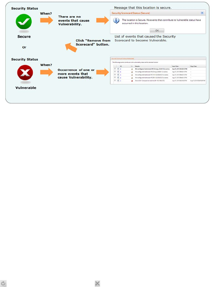
Dashboard
163
Security Status
•
AirTight Devices
This chart presents the AirTight devices and their operating modes. Use the status filter to view, all,
active or inactive devices.
•
AP Classification
This chart presents the Access Points based on their categories. Use the status filter to view, all,
active or inactive APs.
•
Client Classification
This chart presents the clients based on their categories. Use the status filter to view, all, active or
inactive clients.
•
Latest Security Events
This table lists the last events observed at this location. Use the Time, Severity and Number filters
to respectively view the events occurred during a specific period of time, of a desired severity, and
the number of events.
•
Devices in Quarantine
This chart presents the Access Points and clients in various states of quarantine.
•
Top Security Event Categories
This chart presents the number of events by categories. Use the time filter to filter events occurred
during a specific period of time.
• Activation Switches
The Activation Switches widget displays the status of the event activation and intrusion prevention
policies. You can make changes to these policies from this widget. Click the Event Activation or the
Intrusion Prevention switch on the widget to navigate to the respective page and then activate or
deactivate the event activation or wireless intrusion prevention.
Click to refresh the data on the widget. Click to close the widget.
Network Widgets
AirTight Management Console User Guide
164
You can see widgets related to network by clicking Network on the dashboard. The network widgets on
the dashboard are as follows.
•
Location Map
This widget displays your network locations along with the number of managed APs, the number of
associations and the number of associated smart phones and tablets at each location. to use this
widget, upload an appropriate map for each location folder and a floor plan for each loc
ation floor in the location tree. Drag and place your managed APs at the correct locations on the
floor plan corresponding to their physical deployment.
•
Locations by APs
This widget displays up to five locations with the most number of APs. You can view active or
inactive APs for the selected location by selecting the appropriate option at the top of the widget.
You can also view both active and inactive APs for the selected location, by selecting All. You can
filter the content by selecting a SSID available in the widget.
•
Active APs Trend
This widget trends the number of active APs over time. Use the SSID and status filters to
respectively view the statistics for a specific Wi-Fi network and during a specific period.
•
Associations Trend
This widget trends the number of association clients over time. Use the SSID and status filters to
respectively view the statistics for a specific Wi-Fi network and active/inactive APs.
•
AP Data Transfer Trend
This chart trends the average data rate across all managed APs at the selected location over time.
Use the SSID and Time filters to respectively view the statistics for a specific Wi-Fi network and
during a specific period.
•
Smart Device Associations by SSID
This widget displays the currently active number of smartphones and tablets associated per SSID
at the selected location.
•
Data transfer by SSID
This chart displays the top SSIDs by data transfer. The SSIDs should be configured on managed
APs. use the Number and Time filters to respectively view the number of top SSIDs and during a
specified period.
•
Average Association by SSID
This chart displays the average number of associations per SSID over time.
•
Locations by Associations
This chart displays the locations based on the number of associations. Use the SSID, Time,
Top/Bottom and the Number filters to respectively view the Statistics for a specific Wi-Fi network,
during a specific period, top or bottom and the number of locations.
•
Latest Performance Events
This chart displays the latest performance events for the location. Use the Time, Severity and
Number filters to respectively view the events occurred during a specific period of time, of a
desired severity, and the number of events.
•
Average Data Transfer
This chart displays the locations based on average data transfer. Data transfer includes both uplink
and downlink. It is only for Access Points managed through AirTight Management Console. Use
the SSID, Time, Top/Bottom and the Number filters to respectively view the Statistics for a specific
Wi-Fi network, during a specific period, top or bottom and the number of APs.

Dashboard
165
In general, click , wherever available, to refresh the data on the widget. Click to view a description
of the widget functionality. Click to close the widget.
Client Widgets
You can see widgets related to clients by clicking Clients on the dashboard. The client widgets on the
dashboard are as follows.
•
Smart Devices Distribution
This chart displays the number of smart phones and tablets on your Wi-Fi network. Use the SSID
and Time filters to respectively view the statistics for a specific Wi-Fi network and during a specific
period.
•
Client Protocol Distribution
This chart displays the number of associated clients according to the Wi-Fi protocol they are using:
802.11a, 802.11bg, 802.11an and 802.11bgn. You can filter the data by using the SSID to filter the
statistics for a specific Wi-Fi network.
•
Clients by Traffic
This chart displays clients based on the amount of traffic generated. Traffic includes both uplink
and downlink data transferred. Use the Time, Top/Bottom and the Number filters to respectively
view the Statistics during a specific period, top or bottom and the number of clients.
•
Clients by Data Rate
This chart displays clients based on the average data rate. Clients experiencing very low data rate
may be in the fringe areas of your Wi-Fi network or they may be low speed legacy devices (e.g.,
802.11b). In either case, such clients are likely to impact the net capacity of the Wi-Fi network. Use
the Time, Top/Bottom and the Number filters to respectively view the Statistics during a specific
period, top or bottom and the number of clients.
In general, click , wherever available, to refresh the data on the widget. Click to view a
description of the widget functionality. Click to close the widget.
Access Point Widgets
You can see widgets related to access points (AP) by clicking Access Point on the dashboard. The AP
widgets are as follows.
•
APs by Association
This chart displays upto 10 APs with the most or least number of associated clients.
Click and select Chart type as Top (to view APs with most number of associated clients) or
Bottom (to view APs with least number of associated clients). Enter the maximum number of APs
to view on the widget, and click Save.
Use the SSID and Time filters to respectively view the statistics for a specific Wi-Fi network and
during a specific period.
•
APs by Traffic
This chart displays upto 10 APs with the most or least traffic, including downlink and uplink. Click
and select Chart type as Top (to view APs with most traffic) or Bottom (to view APs with
least traffic). Enter the maximum number of APs to view on the widget, and click Save.

AirTight Management Console User Guide
166
Use the SSID and Time filters to respectively view the statistics for a specific Wi-Fi network and
during a specific period.
•
APs by Utilization
This Chart displays the APs which utilize the channel the maximum. AP channel utilization is
defined as the act of the AP either transmitting or receiving any frames. Data and management
frames are considered for this calculation.
Click and select Chart type as Top (to view APs with most utilization) or Bottom (to view APs
with least utilization). Enter the maximum number of APs to view on the widget, and click Save.
•
APs by Data Rate
This chart displays APs based on average data rate. Data Rate includes both downlink and uplink.
Very low data rate at an AP may indicate coverage issues or the presence of low speed legacy
devices (e.g., 802.11b) in the network and is likely to impact the net capacity of the AP.
Click and select Chart type as Top (to view top APs by data rate) or Bottom (to view bottom
APs by data rate). Enter the maximum number of APs to view on the widget, and click Save.
Use the SSID, Time, Top/Bottom and the Number filters to respectively view the Statistics for a
specific Wi-Fi network, during a specific period, top or bottom and the number of APs.
•
AP Security Distribution
This chart displays the live number of APs by their security settings: Open, WEP, WPA, 802.11i
(WPA2). Use the SSID filter to view the statistics for a specific Wi-Fi network.
•
AP Protocol Distribution
This chart displays the live number of APs by their Wi-Fi protocol settings: 802.11a, 802.11bg,
802.11an and 802.11bgn. Use the SSID filter to view the statistics for a specific Wi-Fi network.
In general, click , wherever available, to refresh the data on the widget. Click to learn more about
the widget functionality. Click to close the widget.
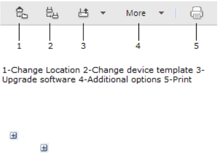
167
Devices
The Devices page provides information about APs, clients, and AirTight devices visible to the system.
You can view device properties, sort the display based on their properties, and change the device
template used. You can view the APs, clients, networks associated with the devices.
Select a location to view devices at that location.
The AirTight Devices tab displays a list of AirTight devices associated with the selected location.
The APs tab displays a list of access points associated with the selected location.
The Clients tab displays a list of clients associated with the selected location.
The Networks tab displays a list of networks detected at the selected location.
AirTight Devices
The Devices>AirTight Devices tab displays all the AirTight devices associated with the selected
location. AirTight devices are the access point/sensor devices from AirTight.
Select an AirTight device to view the list of APs, clients and VLANs visible to the AirTight device.
The AirTight Devices tab is divided into two panes. The upper pane shows a list of AirTight devices for
the selected location. On selecting a device on the upper pane, the device properties related to the
selected device are displayed in the lower pane. In the lower pane, you can view a list of VLANs, APs,
and clients visible to the selected device. You can also view in the lower pane, a list of active APs, active
clients visible to the selected device, and the interference experienced by the device during the past 12
hours.
A toolbar is seen between the two panes as shown in the figure below. You can perform various
operations related to the AirTight devices using the options present on the toolbar.
To perform any operation facilitated by the toolbar, you need to select an AirTight device row in the upper
pane.
Note: The options available to perform various operations depend on the role of the user that has logged
in.
A (plus sign) is located on the left most corner of each device row in the upper pane.
Click the to view the a brief description of the AirTight device. The description indicates whether the
device is operating as a sensor or as an AP, and provides information about the radios being used. If the
device is operating as an AP, the frequency band, channel and background scanning information is also
displayed.
If you want to customize the device template settings for a specific device, you can do it through device
properties.

AirTight Management Console User Guide
168
The following table provides a description of the fields seen in the upper pane of the AirTight Devices
tab.
Field
Description
Active Status
Indicates whether the AirTight device is currently active or not.
Upgrade Status
Indicates if the AirTight device has been successfully upgraded.
Troubleshoot
Status
Indicates the troubleshoot status of the AirTight device. The possible
values are 'Troubleshooting on', 'Troubleshooting off'.
Quarantine Status
Indicates if the device is quarantined.
Name
A user-defined name of the AirTight device.
MAC Address
The unique 48-bit address of the AP/ 802.11 PHY modes used by the
AP.
IP Address
The IP address of the AirTight device.
Model
The AirTight device model number.
Device Template
The device template applied to the AirTight device.
AP Mode
Indicates whether AP mode is enabled or disabled.
Capability
The 802.11 protocol used – 802.11a, 802.11b only, 802.11b/g, or
802.11a/b/g, with or without 802.11n capability.
Location
The location of the AirTight device.
Build
The firmware build number
Up/Down Since
Date and time since the AirTight device is up or down.
Monitored VLANs
Number of VLANS being currently monitored of the total number of
VLANs to monitor.
Configuration
Status
Indicates the configuration status of the AirTight device. The possible
values are 'Allowed and Co
nfigured', 'Not Allowed and Configured', '
Allowed and Not Configured', 'Not Allowed and Not Configured'.
Operating Mode
Current mode of operation of the AirTight device.
Mesh Mode
Indicates whether mesh mode is enabled or disabled.
Device Properties
Each operating region has its own laws governing the use of the unlicensed frequency spectrum for
802.11 communications and Turbo mode. When you select an operating region, the system automatically
selects the channels that are allowed by the regulatory domain in selected region.
Certain Atheros Chipset based devices use wider frequency bands on certain channels in 802.11 b/g and
802.11a band of channels. The system is capable of monitoring channels that support Turbo Mode of
operation and detecting any unauthorized communication on these channels. You can select specific or
all channels to monitor wireless activity on Turbo channels. There are ten Turbo channels in a-mode.
These channels are 40, 42, 48, 50, 56, 58, 152, 153, 160, and 161. There is only one Turbo channel in
b/g-mode, that is 6.
AirTight devices functioning as sensors scan WLAN traffic on specific channels, and defend the network
against various WLAN threats on these channels. These channels are dependent on the operating region
of the AirTight device operating in sensor mode.

Devices
169
The following table describes the device properties.
Field
Description
Currently
Active?
State of the AirTight device. Yes indicates that the device is active, and No
indicates that the device is inactive.
Name
Name of the AirTight device.
MAC Address
A unique 48-bit address of the AirTight device/ 802.11 PHY modes used by
the AirTight device.
Device Tag
Text that provides additional information about the AirTight device.
Country of
Operation
Country in w
hich the AirTight device operates.
Model
AirTight device model number.
IP Address
IP address of the AirTight device.
Device
Template
Device template applied to the AirTight device.
Location
Location of the AirTight device.
Placed on Floor
map?
Specifies whether the AirTight device has been placed on the floor map layout
for the location.
Up/Down Since
Date and time since the AirTight device is up or down.
Channel Scan
Capability (a)
802.11a channels that the AirTight device is configured to scan. This field is
populated based on the country of operation of the AirTight device.
Channel Defend
Capability (a)
802.11 a channels that the AirTight device is configured to defend. This field
is populated based on the country of operation of the AirTight device.
Channel Scan
Capability (b/g)
802.11 b/g channels that the AirTight device is configured to scan. This field
is populated based on the country of operation of the AirTight device.
Channel Defend
Capability (b/g)
802.11 b/g channels that the AirTight device is configured to defend. This
field is populated based on the country of operation of the AirTight device.
Channel Scan
Capability
(Turbo a)
Turbo 802.11a channels that
the AirTight device is configured to scan. This
field is populat
ed based on the country of operation of the AirTight device.
Channel Scan
Capability
(Turbo b/g)
Turbo 802.11b/g channels that
the AirTight device is configured to scan.
This
field is populated based on the country of operation of the AirTight device.
Software Build
Build number of the software on the device.
First Detected
At
Date and time when the AirTight device was first detected by the server.
Operating Mode
Mode in which the device is currently operating. The AirTight device could
operate either
as an AP or as a sensor, depending on the device template
applied to it.
Capability
802.11 protocol used by the AirTight device – 802.11a, 802.11b only,
802.11b/g, or 802.11a/b/g, with or without 802.11n capability.
SSIDs
configured
SSIDs configured for the AirTight device on a radio. This field repeats for each
radio.
Device Specific
Customization
This field is visible only if the Airtight device is in an exclusively AP mode or in
AP mode with background scanning enabled. You can override the device
template settings if the per device configuration is enabled on the device
template applied to the AP
, and customize the settings. Double-click here to
customize theradio settings such as Operating Channel, Custom Transmit
Power, and the mesh node settings for the AP Refer to Customize Device
AirTight Management Console User Guide
170
Template Settings for more details.
Additional
VLAN
Monitoring
Customized additional VLAN monitoring settings. You can customize the
additional VLANs monitored and override the additional VLANs monitored by
the device and customize the settings. Double
-click here to customize the
additionally monitored VLANs. Refer to
Customize Device Template Settings
for more details.
Is Mesh Root
Node (Radio
<number>)?
Indicates whether or not radio 1 for the AP is in a mesh wireless network and
the AP is a root node .
'Yes' indicates that the AP is a root node. You can edit this field only if the
device template applied to this device has per device customization enabled
on it. You can select 'Yes'only if the radio ha
s a mesh profile attached to it.
'No' indicates that the AP is a non-root node.
Edit Device Properties
Some device properties are editable, others are not. To edit a device property, double-click it, edit it and
save the new value.
Customize Device Template Settings
You can customize and override some settings for a device applied through the device template, if you
have selected the Allow Device Specific Customization check box when defining the device template.
You can customize the radio settings and the additional VLANs monitored in the device properties of the
device.
You can customize the radio settings for an AirTight device operating in the AP mode, by modifying the
radio settings in the Device Properties.
These settings override the settings done through the device template applied to the AirTight device.
To customize the radio settings, do the following.
1. Click Devices.
2. Select the AirTight Devices tab.
3. Go to Device Properties.
4. Double-click the Radio Settings in Device Properties. You can customize the operating channel
and/or the transmit power of the radio.
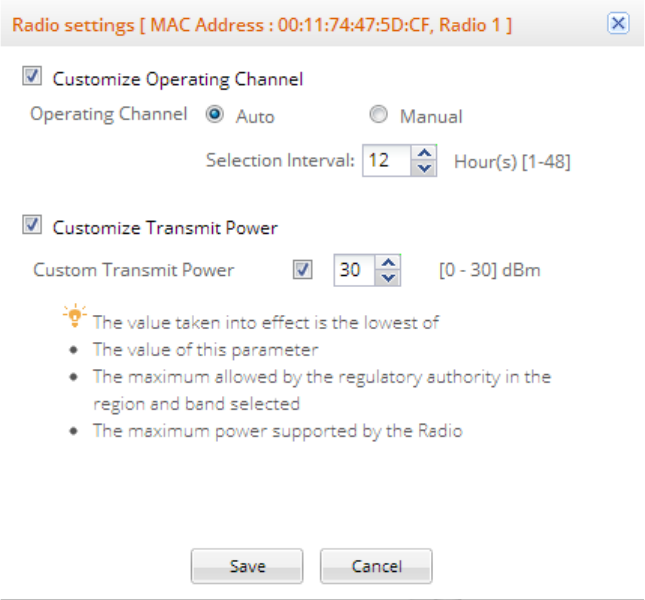
Devices
171
Customize Radio Settings for an AirTight Device
To customize the operating channel, do the following.
1. Select the Customize Operating Channel check box.
2. If you want an auto selection of channel, select Auto and specify the channel selection interval, in
hours, in the Selection Interval.
3. If you want to manually set the channel, select Manual and select the Channel Number.
Note: You are not allowed to change the operating channel for a mesh radio.
To customize the transmit power, do the following.
1. Select the Customize Transmit Power check box.
2. Select the check box next to Custom Transmit Power and specify the value. If you do not select the
check box next to Custom Transmit Power, the value is set to maximum permissible transmit power for
the country of operation for the AP.
To customize the additional VLANs monitored, do the following.
1. Select the device for which you want to customize the additional monitored VLANs.
2. Click the Additional VLAN Monitoring properties in Device Properties. The Device Specific
Customization for Additional VLAN Monitoring dialog box appears.
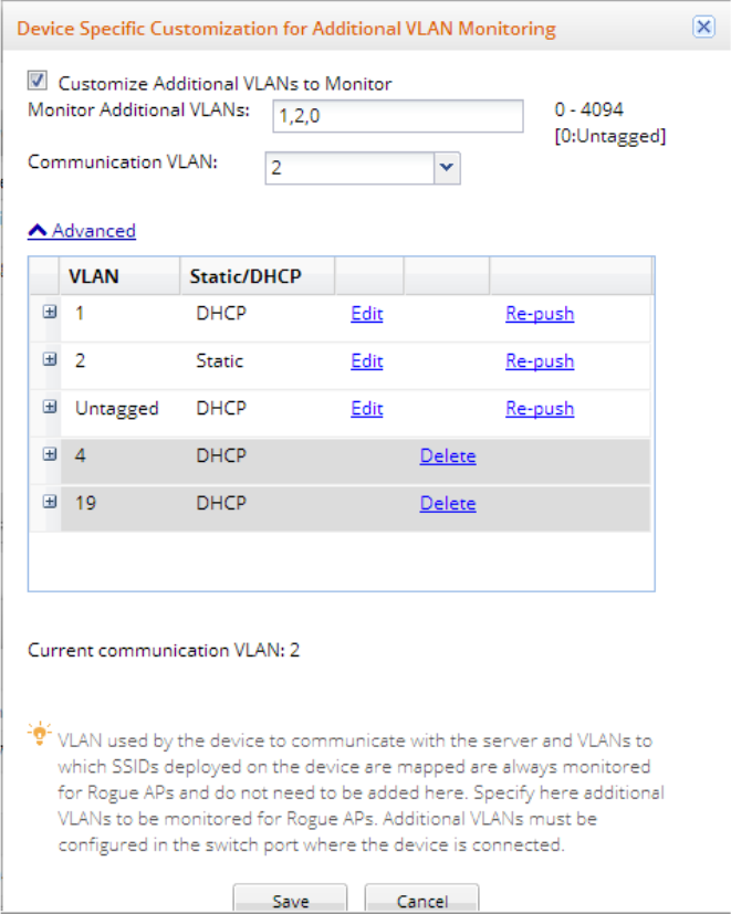
AirTight Management Console User Guide
172
3. Select the Customize Additional VLANs to monitor check box.
4. Specify the additional VLANs to be monitored as a comma-separated list.
5. Change the communication VLAN, if needed. 0 is the communication VLAN. However, you can
specify another number as the communication VLAN. Before the 6.7 Update 5 release, the
communication VLAN was set from the CLI only with the set vlan config command.
Note: Prior to the 6.7 Update 5 release, the communication VLAN could be only set from the CLI.
From the 6.7 Update 5 release, it can be done from the AirTight Management Console.
IMPORTANT: After the communication VLAN has been set from the UI, it cannot be modified from
the CLI. If you have set an incorrect communication VLAN from the UI, and want to change it, you
have to first do a factory reset of the AirTight device, and then set the correct communication
VLAN.
6. Click Advanced to do advanced operations such as editing the VLAN properties of the additionally
monitored VLANs and to repush the IP settings of these VLANs on to the AP or WIPS sensor.
a) To edit the VLAN properties of the VLANs, click Edit. Change the addressing mechanism to static
or DHCP as required and save the change.
b) To re-push the revised IP settings of the additionally monitored VLANs on to the AirTight device,
click Repush and then Save. If you want to cancel the repush, click Cancel before you click Save.
The text on the link changes to repush pending until an acknowledgement is received from the
AirTight device.

Devices
173
c) You might see a few VLANs with the Delete link under Advanced. These are the previously
monitored additional VLANs that are no longer relevant. You must delete these from the monitored
list.
7. Click Save below Additional VLAN monitoring on Device Properties to save the customization to
the additional monitored VLANs for the device.
View Visible LANs
Under the Visible LANs section, you can view a list of LANs that are visible to the selected AirTight
device if it is operating as a WIPS sensor. VLAN details such as VLAN ID, IP Address, Net Mask, and
Status are displayed. The VLAN over which the sensor communicates with the server is marked with an
asterisk(*).
View Visible APs
Click located below the device listing to view the Visible APs section. Under the Visible APs section,
you can view a list of APs that are visible to the selected AirTight device if the device is operating as a
WIPS sensor. AP details, such as name and RSSI received by the sensor, are displayed in the rows.
View Visible Clients
Click located below the device listing to view the Visible Clients section. Under the Visible Clients
section, you can view a list of clients that are associated with or seen by the selected AirTight device.
Client details such as Name and RSSI received by the sensor are displayed in the rows.
View Active APs
Under the Active APs section, you can select a channel number to view a graphical representation of the
active APs over the past 12 hours on that channel. The APs visible to the AirTight device selected in the
upper pane are seen here.
View Active Clients
Under the Active Clients section, you can select a channel number to view a graphical representation of
the active clients over the past 12 hours on that channel. The clients visible to the AirTight device
selected in the upper pane are seen here.
View AirTight Device Events
Under the Events section, you can see the events related to the AirTight device.
View Channel Occupancy
Under the Channel Occupancy section, you can view a graphical representation of the active APs and
active clients on various channels based on the time selected by you. Click the time duration hyperlink to
select the number of hours for which you want to see the channel occupancy.
Click Channel Map to view the channel map based on the selected band and time in the form of a bar
graph.

AirTight Management Console User Guide
174
View Interference
Under the Interference section, you can select a channel number to view a graphical representation of
the interference experienced over that channel in the past 12 hours. The interference seen here is visible
to the AirTight device selected in the upper pane.
View Mesh Network Links
This is relevant only if the selected AirTight device is part of a mesh wireless network.
1. Click Devices.
2. Select the AirTight Devices tab.
3. Click located below the device listing to view the mesh network links with respect to the selected
AirTight device.
4. The AirTight AP that is the immediate parent of the selected AirTight (AP) device in the mesh network
topology is seen in Up Link. The device name and the RSSI of the parent of the selected device is
seen in Up Link. The AirTight APs that are connected to the selected AirTight AP as child nodes in
the mesh network topology are seen in Down Links. The device name and the RSSI of the child
nodes of the selected device are seen in Down Links.
Search AirTight Devices
You can search for an AirTight device using name or MAC address in the search string. All the AirTight
devices having the search string or substring in their name or MAC address are displayed.
To search for one or more than one AirTight devices, do the following.
1. Click Devices.
2. Select the AirTight Devices tab.
3. Enter the name or MAC address in Quick Search box at the top right corner.
4. Press the Enter key. The search result displaying the AirTight devices matching the search string
appears.
Sort AirTight Devices
You can sort the columns in the tab in ascending or descending order, and can choose the columns to be
displayed. Point to a column in the device list and click to sort on the column or choose the columns to
be viewed.
Change Location
To change the location of a device, do the following.
1. Click Devices.
2. Select the AirTight Devices tab.
3. Select the AirTight device from the list of devices.
4. Click the Change location icon. The select location dialog box appears.
5. Select the new location for the AirTight device.
6. Click OK. The device is moved to the new location.
Print AirTight Device Information for Location
Devices
175
You can print all the information seen for all AirTight devices in the upper pane. You can choose the
columns to be viewed on the UI by selecting them. The information seen in the upper pane is the
information that will be seen in the printout.
If pagination is enabled, the list of AirTight devices on the current page are printed. To print a list of all
AirTight devices for a location, you must go to each page and print the individual pages.
If pagination is disabled, only the list of AirTight devices visible on the UI is printed. This means that if
there are 25 records of which only the first five have been presented on the UI, these five records are
printed.
You must enable or disable pagination before you print.
To print the AirTight devices list for a location, do the following.
1. Click Devices and then click the AirTight Devices tab.
2. Select the location.
3. Select the columns that you want in the printed list. Click any column name to select or deselect
columns.
4. Click the print icon. The print preview of the AirTight devices list appears.
5. Click Print to print the list.
Change Device Template
To change the device template for an AirTight device, do the following.
1. Click Devices.
2. Select the AirTight Devices tab.
3. Select the AirTight device.
4. Click the Change device template icon present on the toolbar. The Change Device Template dialog
box appears.
5. Select a device template from the available list of device templates
6. Click Save to save the changes.
Reboot Device
To reboot an AirTight device do the following.
1. Click Devices.
2. Select the AirTight Devices tab.
3. Select the AirTight device from the device list.
4. Click the More>Reboot device icon present on the toolbar. A reboot confirmation message is seen.
5. Click Yes to reboot the device. Click No if you do not wish to reboot the device.
Troubleshoot Device
An active AirTight device can troubleshoot itself. For active AirTight devices, you can troubleshoot in the
packet level mode.
When you initiate troubleshooting, you must ensure that the AirTight device is reachable from the
computer used to launch the AirTight Management Console.
You can troubleshoot using packet capture tools like Wireshark or any other tool available to you.
Alternatively, you can save the packet trace history to the AirTight server and download the history file to
save it for future reference. The packet trace history is saved as a .pcap file. This can also be viewed
using Wireshark.
AirTight Management Console User Guide
176
A troubleshooting session automatically times out or terminates after the specified timeout irrespective of
the activity. Refer to the 'Stop Troubleshooting' sub-section in this section to manually terminate a
troubleshooting session.
If you are an AirTight Cloud Services user, you can upload the packet capture file directly into WizShark.
You can then use WizShark to analyze the packet capture or trace files. Following are the prerequisites to
successfully upload the file to WizShark.
• You must have subscribed to the WizShark service.
• You must have upload privileges in WizShark.
• The file size must not exceed the maximum file size prescribed by WizShark.
• When the file is uploaded, the total storage quota for your account must not be exceeded.
Troubleshoot AirTight Device using Wireshark on Local Machine
To troubleshoot an AirTight device, do the following.
1. Click Devices.
2. Select the AirTight Devices tab.
3. Select the check box for the AirTight device to troubleshoot.
4. Click the More>Packet Capture option on the tool bar.
5. Select the Live Packet Capture option under Troubleshooting Mode. The Troubleshoot AP dialog
box appears.
6. Select Streaming option as Wireshark on local machine.
7. Specify the time-out interval in Timeout. The default time-out for packet level troubleshooting mode is
5 minutes. Minimum allowed value is 1 minute and maximum is 720 minutes for the time-out.
8. Select the packet type. If you want to capture all packets, select the All option. If you want to capture
only specific packet types, select the filter option and then select the required data frames and/or
management frames to capture while troubleshooting.
9. In the Protocol and Channel Selection section, select the protocols and channel for which you want
to troubleshoot. If you want to select a single channel, select the Select Channel option and specify
the channel number and Width (channel offset). By default, the protocol and channels are displayed
based on the device template applied to the troubleshooting sensor. You can select a different
protocol and/or channel, if required. Alternatively, you can select the Rotate on all Channels option,
to troubleshoot on all available channels.
10. Click Start Troubleshooting to start the troubleshooting. The sensor is enabled to capture live
packets.
11. Select an appropriate tool for live packet capture. If you don't have the tools already installed, you
can download Wireshark or any other tool.
12. To view the packet capture, open the command line interface of the operating system installed on
your computer and execute the command shown under Wireshark depending on the tool you use.
The Troubleshooting in Packet Level Mode dialog box gives a guideline to the command to
execute for Wireshark.
Troubleshoot AirTight Device to upload Packet History to AirTight server
To troubleshoot an AirTight device, do the following.
1. Click Devices.
2. Select the AirTight Devices tab.
3. Select the check box for the AirTight device to troubleshoot.
4. Click the More>Packet Capture option on the tool bar.
5. Select the Live Packet Capture option under Troubleshooting Mode. The Troubleshoot AP dialog
box appears.
6. Select Upload to Server as Streaming option.
Devices
177
7. Enter a suitable prefix for the file name in Filename Prefix. This helps you identify the
troubleshooting files when you download the packet history.
8. Specify the time-out interval in Timeout. The default time-out for packet level troubleshooting mode is
5 minutes. Minimum allowed value is 1 minute and maximum is 720 minutes for the time-out.
9. Select the packet type. If you want to capture all packets, select the All option. If you want to capture
only specific packet types, select the filter option and then select the required data frames and/or
management frames to capture while troubleshooting.
10. In the Protocol and Channel Selection section, select the protocols and channel for which you want
to troubleshoot. If you want to select a single channel, select the Select Channel option and specify
the channel number and Width (channel offset). By default, the protocol and channels are displayed
based on the device template applied to the troubleshooting sensor. You can select a different
protocol and/or channel, if required. Alternatively, you can select the Rotate on all Channels option,
to troubleshoot on all available channels.
11. Click Start Troubleshooting to start the troubleshooting. The sensor is enabled to capture live
packets.
Stop Troubleshooting
A troubleshooting session automatically times out or terminates after the specified timeout irrespective of
the activity. You can manually terminate a troubleshooting session.
To stop an active troubleshooting session manually, do the following.
1. Click the Notifications icon at the top right corner. The active troubleshooting sessions are displayed
along with other notifications, if any.
2. Click the notification for active troubleshooting sessions. A list of sensor troubleshooting sessions is
displayed.
3. Select the check box for the troubleshooting session to terminate.
4. Click Stop. The troubleshooting session is terminated and a message indicating the termination of
the troubleshooting session is displayed. If the Upload to Server option has been selected as
Streaming option under Troubleshooting Mode, the packet trace history is uploaded to the AirTight
server.
Download Packet Capture
AirTight server maintains a packet capture history for the troubleshooting instances for a period of 30
minutes, after you stop troubleshooting.
You can download this history and save them for future reference. The packet traces are available in
.pcap format.
To download a packet trace file, do the following.
1. Select the required location from the location tree.
2. Click Devices.
3. Select the AirTight Devices tab.
4. Click the More>Previous Packet Captures option on the tool bar.The Packet Capture dialog box
appears. The list of files is displayed with the file name, file size in KB, troubleshooting start time and
troubleshooting stop time.
5. Click the Download link for the packet trace to download and select the path to store the packet
trace. The packet trace file is saved to the specified location.
If you are an AirTight Cloud Services user, and wish to upload the packet capture file to WizShark from
AirTight Management Console, click the View in WizShark link. The file is directly uploaded to WizShark
AirTight Management Console User Guide
178
and WizShark opens up in a separate browser tab or browser window. You can then analyze the packet
capture file using WizShark.
Delete Packet Capture File
AirTight server maintains a packet capture history for the troubleshooting instances for a period of 30
minutes, after you stop troubleshooting.
You can delete this packet capture history from the server. The packet capture files are available in .pcap
format.
To delete a packet capture file, do the following.
1. Select the required location from the location tree.
2. Click Devices.
3. Select the AirTight Devices tab.
4. Click the More>Previous Packet Captures option on the tool bar. The Previous Packet Capture
dialog box appears. The list of files is displayed with the file name, file size in KB, troubleshooting
start time and troubleshooting stop time.
5. Select the check box for the log file to delete. You can select multiple files to delete at a time.
6. Click the icon. A message to confirm the deletion appears
7. Click Yes to confirm deletion of selected files.
Upgrade or Repair Device
To upgrade or repair a device, do the following.
1. Click Devices.
2. Select the AirTight Devices tab.
3. Select one or more devices operating in the same mode.
4. Click the Upgrade software icon present on the toolbar.
5. Select the appropriate option from Upgrade, Repair, Cancel Upgrade, Cancel Repair, Cancel
Upgrade/Repair.
Option
Description
Upgrade
Upgrade to a newer software version for the device.
Cancel Upgrade
Cancel the upgrade after you have initiated it and the
upgrade operation is still in progress.
Repair
Fix the problem in the device software without change in
software version like applying a patch.
Cancel Repair
Cancel the repair after you have intiated it and the repair
operation is still in progress.
Cancel
Upgrade/Repair
Cancel upgrade or repair as applicable while the
operation is still in progress.
Enable Pagination for AirTight Device Listing and Set Page Size
By default, the AirTight device listing in the upper pane is presented in a grid. You can scroll down to the
last AirTight device row in the upper pane without having to browse across pages. A paginated view is
also available if you want to view a page-wise list of AirTight devices. You can enable pagination for the
AirTight devices that are visible to you and configure the number of rows on each page in the upper pane.
Devices
179
To enable pagination, do the following.
1. Go to Devices>AirTight Devices tab.
2. Click the icon seen on the right side of the tool bar. A message to confirm pagination for all
grids/listings on the UI appears.
3. Click OK. The pagination for AirTight device listing is enabled. The pagination for all other grids such
as clients, APs, networks, events and AirTight Mobile clients is enabled as well. Note that this setting
is restricted to your login only and is not applicable to other users.
To set the page size, do the following.
1. Go to Devices>AirTight Devices tab.
2. On the tool bar, click the down arrow next to the number of rows displayed to the left of the icon.
The options First Page and Set page size appear.
3. Click Set Page Size and enter the number of rows to be visible on each page.
4. Click OK.
You can browse through the paginated AirTight device listing by clicking the (next page) and
(previous page) icons. To go to the first page, click the down arrow next to the number of rows on the
page and select the First page option.

AirTight Management Console User Guide
180
Disable Pagination for AirTight Device Listing
If you have enabled pagination and want to disable it, you can restore the default view of having a
complete listing of all AirTight devices on a single page.
To disable pagination, do the following.
1. Go to Devices>AirTight Devices tab.
2. Click the icon seen on the right side of the tool bar. A message to confirm disabling of pagination
for all grids/listings on the UI appears.
3. Click OK. The pagination for AirTight device listing is disabled. The pagination for all other grids such
as clients, APs, networks, events and AirTight Mobile clients is disabled as well. Note that this setting
is restricted to your login only and is not applicable to other users.
Add Custom Filter
You can create custom filters and save them with the name of your choice. You can select the columns to
be viewed and can, optionally, set a filter on the data in the columns seen on AirTight Management
Console. You can save this filter with a name and can create multiple filters in this manner.
Note the following points when working with custom filters.
• Preferences for visibility of columns and sorting of column data are not saved in a custom filter. Only
the filter criteria is saved.
• Custom filters are user-specific. They are saved for the user who has defined the custom filter and is
not visible to any other user.
• An unsaved filter is indicated by an asterisk next to the filter name seen next to Filter on the tool bar.
• An unsaved filter is not saved if the user logs out without saving the filter.
To create a custom filter, do the following.
1. Go to Devices>AirTight Devices.
2. Click the icon next to a column header. A list of options is displayed.
3. Point the mouse at the Filters option and enter the filter text for the column.
4. Click the icon next to Filter on the tool bar and click Save as. The Save as dialog box appears.
5. Enter the name of the filter and click OK. The custom filter is saved.
Edit Custom Filter
To edit a custom filter, do the following.
1. Go to Devices>AirTight Devices.
2. Click the icon next to Filter on the tool bar and select the required filter.
3. Click the icon next to a column header. A list of options is displayed.
4. Point the mouse at the Filters option and enter the filter text for the column or make changes to the
filter criteria as required.
5. Click the icon next to Filter on the tool bar and click Save. The modified custom filter is saved.
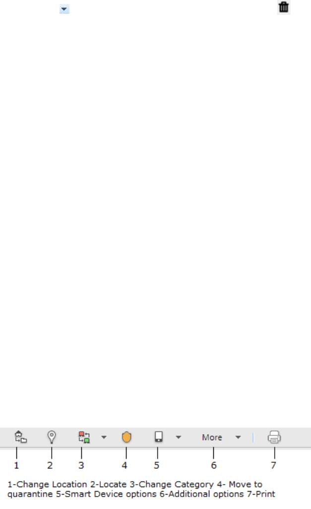
Devices
181
Delete Custom Filter
To delete a custom filter, do the following.
1. Go to Devices>AirTight Devices.
2. Click the icon next to Filter on the tool bar and click the icon for the filter to delete. A message
asking you to confirm delete appears.
3. Click Yes to confirm deletion of the custom filter.
Delete Device
To delete an AirTight device, do the following.
1. Click Devices.
2. Select the AirTight Devices tab.
3. Select the AirTight device to be deleted.
4. On the toolbar, click the Delete icon.
5. Click Yes to confirm the deletion.
Monitor Clients
The Devices>Clients tab displays all the clients associated with the selected location.
Select from category Authorized, Rogue, External, Uncategorized to view the list of authorized, rogue,
external or uncategorized clients. You can choose one or more of these categories at a time. Select All to
view clients from all categories.
The Clients tab is divided horizontally into two panes. The upper pane shows a list of clients for the
selected location. The lower pane shows the client properties related to the client you select in the upper
pane of the Clients tab. You can view a list of APs or ad hoc networks recently associated with the
selected client, in case of authorized, rogue, external and uncategorized clients.
Both active and inactive clients are visible in the Clients tab. Inactive clients of some categories are
visible in specific deployments only.
In case of authorized clients, you can also view client traffic, client average data rate in the lower pane.
You can perform various operations related to the clients using the options present on the toolbar as
shown in the image below.
To perform any operation facilitated by the tool bar, you need to select a client row in the upper pane. You
can select multiple clients for some operations like delete.
Note: The options available to perform various operations depend on the role of the user that has logged
in.

AirTight Management Console User Guide
182
Station virtual APs of the non-root mesh APs that are connected to uplink mesh APs in a wireless mesh
network are seen as clients. These are categorized as Authorized, by default. You cannot change the
category of these clients. You cannot quarantine or automatically ban such clients. Hence the options
under More in the toolbar are disabled for such clients.
You can sort the client information based on the columns in the upper pane of the Clients tab in
ascending or descending order, and can choose the columns to be displayed. Point to a column and click
to sort on the column, choose the columns to be viewed, or filter the data to be viewed based on filter
text matching the text in the selected column. For example, if you want to view only the clients at location
'Texas', point to Location click and enter Texas as the filter text. Press the Enter key.
Note: Sorting on the columns AirTight Mobile Status, AirTight Mobile Risk Level and AirTight Mobile
Groups is available in specific deployments only.
You can search for a client by entering the name, MAC address or SSID in Quick Search box at the top
right corner.
The following table provides a description of the fields seen in the upper pane of the Clients tab.
Field
Description
Active Status
Indicates if the client is active or inactive. The status is indicated
with the help of different icons.
Smart Device
Indicates if the client is a smart device.
Quarantine Status
Displays the quarantine status of the client. Possible values are
Quarantine Active, Quarantine Pending, Quarantine Stopped.
RSSI
Displays the observed RSSI (Received Signal Strength Indicator)
value for the client .
Name
Specifies the user-defined name of the client.
MAC Address
Specifies the unique 48-bit IEEE format address of the client
assigned to the network adapter by the manufacturer.
Associated AP
Specifies the AP with which a Client is associated. This is the AP
through which the Client communicates with other Clients and
other networked devices.
SSID
Specifies the operating SSID of the AP with which the Client is
associated.
Manually Classified
Indicates if the client has
been manually classified.
Tag
Device tag. Additional information about the client. To be entered
by a user.
Is Banned
Indicates if the client is banned.
AirTight Mobile
Status
Indicates if the client is an AirTight Mobile client, that is if the
client has AirTight Mobile installed on it.
AirTight Mobile
Risk Level
Indicates the risk level of the AirTight Mobile client. This is
applicable only if AirTight Mobile is installed on the client.
AirTight Mobile
Group
AirTight Mobile group of the client. This is applicable only if
AirTight Mobile is installed on the client.
Smart Device
Category of smart device indicated by icon if the device is a smart
device. The field is blank if the device is not a smart device.
Smart Device Type
Type of smart device.
Vendor
Client manufacturer. The vendor name is inferred from the first
three bytes of the MAC address.

Devices
183
Location
Location of the client.
Protocol
802.11 protocol (with or without 802.11 n or 802.11ac capability)
used by the AP with which the Client is associated.
Up/Down Since
Date and time since the AP is up or down.
Cell ID
ID for clients in ad hoc mode. The Cell ID is common for all the
Clients that form a single ad hoc connection.
Troubleshooting
Indicates if troubleshooting is in progress for the client. Possible
values are Yes, No.
First Detected At
Date and time at which the client was first detected.
IP Address
IP address of the client.
User name
User ID of the user logged on to the client.
Is Misbehaving
'Yes' indicates that the authorized client is misbehaving. 'No'
indicates that the authorized client is not misbehaving. A '
--'
indicates that the field is not applicable as the client is
unauthorized.
View Client Properties
Some client properties are editable, others are not. A pencil icon is seen to the right of the client
properties value indicating that the property is editable. To edit a client property, double-click it, edit it and
save the new value.
The following table provides a field-wise description of the client properties.
Field
Description
Currently Active?
Indicates if the client is currently active. 'Yes' means that the client
is active. 'No' means that the client is inactive.
Client Name
Host name of the client.
User Name
User ID of the user logged on to the client.
Classification
Indicates whether the client is categorized as Authorized, External,
or Rogue. Uncategorized indicates that the client has not been
categorized.
Device Tag
Additional information about the client.
MAC address
MAC address of the client.
Location
Client location.
Up Since
Date and time since when the client is up.
Is Smart Device
Indicates if the client is a smart device.
Yes
indicates that the client is a smart device.
No indicates that the client is not a smart device
Sm
art Device Type
Indicates the type of smart device, if the client is a smart device.
The field is visible only if the client is a smart device.
Mode of Operation
Specifies whether the Client is connected to an AP or to a peer-to-
peer network
Infrastructure mode indicates that the client is connected to an AP.
Ad hoc mode indicates that the client connected to a peer
-to-peer
network.
Ad hoc Cell ID
Unique ID of the ad hoc network connection of which the selected
Client is a member.

AirTight Management Console User Guide
184
IP Address
IP address of the client.
Vendor
Name of the Client manufacturer. The vendor name is inferred from
the first three bytes of the MAC address.
Protocol
802.11 protocol in which the client is currently operating.
Channel
Channel number that the client operates on.
Security
Security standard applied to the AP. This is derived from the
template applied to the AP.
Network
Additional information about the IP Address and subnet that
identifies the network on which the Client is located.
Associated to AP
BSSID of the AP that the client is associated with.
First Detected at
Date and time when the client was first detected by the system.
Quarantine Status
Indicates if the client is in quarantine.
Defending Sensor
Name
Name of the defending sensor.
Quarantine
Pending Reason
Specifies the reason if quarantine is pending.
Bridging/ICS Mode
Indicates if the client is in bridging/ICS mode. 'Yes' indicates that
the client is in bridging/ICS mode.
'No' indicates that the client is not in bridging/ICS mode.
Running Soft AP?
Indicates if a soft AP is running on the client.
'Yes' indicates that a soft AP is running on the client.
'No' indicates that a soft AP is not running on the client.
WDS Mode
Indicates if Wireless Distribution System (WDS) is enabled. This is
applicable only if the client is an AP, and has connected to a WDS
AP.
Tx STBC 802.11n
Indicates support for transmission of PPDUs using STBC for active.
'Yes' indicates that transmission of PPDUs using STBC is
supported for active 802.1
1n client.
'No' indicates that transmission of PPDUs using STBC is not
supported for active 802.11n client. This field is visible for active
802.11n clients only.
Rx STBC 802.11n
Indicates support for reception of PPDUs using STBC for active
802.11n client.
If this reception is supported, the number of spatial streams
supported are indicated. Upto 3 spatial streams are supported for
the 802.11n protocol.
If this reception is not
supported, the value of this field is 'Not
supported'.
This field is visible for active 802.11n clients only.
802.11ac Capability
This field is visible for active 802.11ac clients only. It indicates if
the client
has built-in support for 802.11ac protocol.
'Yes' indicates that the client is 802.11ac capable.
Tx STBC 802.11ac
Indicates support for transmission of PPDUs using STBC for the
active 802.11ac client.
'Yes' indicates that transmission of PPDUs using STBC is
supported for the active 802.11ac
client.
'No' indicates that transmission of PPDUs using STBC is not
supported for the active 802.11ac client.
This field is visible for active 802.11ac clients only.
Rx STBC 802.11ac
Indicates support for reception of PPDUs using STBC for active
802.11ac client.

Devices
185
If this reception is supported, the number of spatial streams
supported is indicated. Upto 4 spatial streams are supported for the
802.11ac protocol.
If this reception is not supported, the value of this field is 'Not
supported'.
This field is visible for active 802.11ac clients only.
MU Beamformer
Capability
Indicates support for operation as a multiuser beamformer.
'Yes' indicates that the operation as a multiuser beamformer is
supported.
'No' indicates that the operation as a multiuser b
eamformer is not
supported.
This field is visible for active 802.11ac clients only.
MU Beamformee
Capability
Indicates support for operation as multiuser beamformee.
'Yes' indicates that the operation as a multiuser beamformee is
supported.
'No' indica
tes that the operation as a multiuser beamformee is not
supported.
This field is visible for active 802.11ac clients only.
View Recently Associated APs/Ad hoc networks
Under Recently Associated APs/Ad hoc Networks, you can view a list of APs/Ad hoc networks to
which the Client was associated. APs/Ad hoc network details such as AP Name/Ad hoc ID, BSSID, SSID,
Last Detected At are displayed in the widget. The criterion for Recent Association is either 12 hours or the
total number of APs/Ad hoc Networks (this is the total number of associations in the system and not per
device). The total number of associations maintained by AirTight Management Console depends upon
the number of AirTight devices connected to the AirTight server.
Note: Information related to recently associated APs is available in specific deployments only.
View Events related to Client
Under Events, you can see all the events related to the client. The Event ID, event description, event start
time and event stop time are displayed.
View Client Retransmission Rate Trend
This widget is seen for authorized clients only. You can select the time duration and view a graphical
representation of the client retransmission rate trend over the selected time duration.
View Devices Seeing Client
Under Devices Seeing Client, you can view the active devices that have detected the selected client.
The name of the device and the RSSI of the device are seen in this section. This section is populated for
all types of clients.
AirTight Management Console User Guide
186
View Client Average Data Rate
Client Average Data Rate section is seen only for authorized clients. AirTight device seeing the client
keep track of the transmission rates of the data frames in the AP's BSS and reports weighted average
transmission rate over every 15 minutes.
View Client Traffic
Client Traffic section is seen only for authorized clients. AirTight device seeing the client reports data
traffic sent and received by the client every 15 minutes. The channel rotating AirTight device spends only
a percentage of the total time on any given channel. Hence this parameter typically underestimates the
actual traffic by a factor equal to the total number of channels scanned by the device radio. For example,
if the AirTight device scans 30 channels in all, the measured traffic would be 1/30th of the actual traffic.
However, if the traffic is bursty in nature, such straightforward scaling cannot be applied.
Change Client Location
You can change the client location for a selected client.
To change the client location, do the following.
1. Go to Devices.
2. Select the Clients tab.
3. Select the client for which the location has to be changed.
4. Click the Change location icon. The Select New Location dialog box appears.
5. Select the new location for the client.
6. Click OK. The client is moved to the newly selected location.
Quarantine Client
To quarantine a client, do the following.
1. Go to Devices
2. Select the Clients tab.
3. Select the client to be quarantined.
4. Click the Move to Quarantine icon. You are prompted to confirm the quarantine.
5. Click Yes to quarantine the selected client.
Disable Auto Quarantine/Exclude Device from Intrusion Prevention
Policy
You can exclude a device from the intrusion prevention policy by disabling auto-quarantine for the device.
To disable auto-quarantine, do the following.
1. Go to Devices
2. Select the Clients tab.
3. Select the client for which auto-quarantine is to be disabled.
4. Click More present on the toolbar.
5. Click the Disable auto-quarantine icon present under More, to disable auto-quarantine. A message to
confirm disable auto-quarantine appears.
6. Click Yes to confirm the disabling of auto-quarantine for the device.
Devices
187
Add to banned list
To add a client to the banned client list, do the following.
1. Go to Devices
2. Select the Clients tab.
3. Select the client.
4. Click the Add to banned list icon present on the toolbar. The client is added to the banned list.
Classify / Declassify as Smart Device
To classify a client as a smart device, do the following.
1. Go to Devices
2. Select the Clients tab.
3. Select the client.
4. Click the smart device icon present on the toolbar, to classify or declassify the client as a smart
device. If the client has already been marked as a smart device, you can specify whether it is an
approved or unapproved smart device.
5. To classify the client as a smart device, select Is a Smart Device option. To declassify a smart
device, select Not a Smart Device option.
Change Client Category
To change the client category, do the following.
1. Go to Devices
2. Select the Clients tab.
3. Select the client.
4. Click the Client category icon present on the toolbar, to change the existing client category.
5. Select the desired category from Authorized, External, Rogue, Guest, as the case may be.
Reset Data Transmitted by Client
Note: The Reset RF Fingerprint option is available in specific deployments only.
To reset the data transmitted by a client, do the following.
1. Go to Devices
2. Select the Clients tab.
3. Select the client for which you want to reset the data.
4. Click the Reset RF Fingerprint icon present on the toolbar, to reset the data transmitted by the client.
Locate Client
To locate a client on the floor map, do the following.
1. Go to Devices>Clients tab.
2. Click the Locate icon to locate the client on the floor map.
View Recently Probed SSIDs
AirTight Management Console User Guide
188
To view recently probed SSIDs, do the following.
1. Go to Devices>Clients tab.
2. Select a client.
3. Go to Recently Probed SSIDs widget in the lower pane to view the recently probed SSIDs and its
details for the selected client.
Troubleshoot Client
You can troubleshoot clients using an AirTight device operating in sensor mode.
When you initiate troubleshooting, you must ensure that the AirTight device (sensor) is reachable from
the computer used to launch the AirTight Management Console. If the AirTight device is busy in
quarantine or busy in troubleshooting, it will be not be able to troubleshoot the selected client.
You can have an AirTight device (sensor) troubleshoot the client in packet level mode or event level
mode. This sensor can troubleshoot in packet level mode using packet capture tools like Wireshark or
any other tool available to you.
A troubleshooting session automatically times out or terminates after the specified timeout irrespective of
the activity.
Note: When a troubleshooting session is in progress, a notification regarding the active troubleshooting
session can be seen under Notifications (top right corner of the AirTight Management Console).
IMPORTANT: Once the packet capture based troubleshooting session begins from the Console and the
packet capture tool is either interrupted or terminated (gracefully or abruptly), you have to first stop the
ongoing troubleshooting session from the Console either manually (if it is still going on) or ensure that the
session has indeed ended before you can start another packet capture session. Refer to the 'Stop
Troubleshooting' sub-section in this section to manually terminate a troubleshooting session.
You can then restart the fresh troubleshooting session from the Console.
If a troubleshooting session is in progress with a chosen tool (Wireshark or user specified tool), another
capture from the command prompt, using user specified capture parameters (viz. rpcap://sensor-ip/iface)
will not succeed from the same or another computer.
If you are an AirTight Cloud Services user, you can upload the packet capture file directly into WizShark.
You can then use WizShark to analyze the packet capture or trace files. Following are the prerequisites to
successfully upload the file to WizShark.
• You must have subscribed to the WizShark service.
• You must have upload privileges in WizShark.
• The file size must not exceed the maximum file size prescribed by WizShark.
• When the file is uploaded, the total storage quota for your account must not be exceeded.
Troubleshoot Client in Packet Level Mode
To troubleshoot a client in packet level mode, do the following.
1. Click Devices.
2. Select the Clients tab.
3. Select the check box for the client to troubleshoot.
4. Click the More>Packet Capture option on the toolbar. The Troubleshoot on Client device dialog box
appears.
Devices
189
5. Select the Live Packet Capture option.
6. Specify the timeout interval in Timeout. The default timeout for packet level troubleshooting mode is
5 mins. Minimum allowed value is 1 minute and maximum is 720 minutes for the timeout.
7. Select the type of packets you want to see while troubleshooting under Traffic Selection. If you want
to view all packets visible to the troubleshooting sensor, select the All packets on the channel
option. If you want to view only packets from the client visible to the troubleshooting sensor, select the
Only packets for the selected client <client MAC> option.
8. Select the check box for the sensor using which you want to do the troubleshooting,from the list of
AirTight devices operating as sensors. The sensors seeing the device are sorted based on their
availability and signal strength.
9. In the Protocol and Channel Selection section, select the protocols and channel for which you want
to troubleshoot. If you want to select a single channel, select the Select Channel option and specify
the channel number and Width (channel offset). By default, the protocol and channels are displayed
based on the device template applied to the troubleshooting sensor. You can select a different
protocol and/or channel, if required. Alternatively, you can select the Rotate on all Channels option,
to troubleshoot on all available channels.
10. Click Start Troubleshooting to start the troubleshooting. The sensor is enabled to capture live
packets.
11. Select an appropriate tool for live packet capture. If you don't have the tools already installed, you
can download Wireshark or any other tool.
12. To view the packet capture, open the command line interface of the operating system installed on
your computer, and execute the command shown under Wireshark depending on the tool you use.
The Troubleshooting in Packet Level Mode dialog box gives a guideline to the command to
execute for Wireshark.
AirTight Management Console User Guide
190
Troubleshoot Client in Event Level Mode
To troubleshoot a client in event level mode, do the following.
1. Click Devices.
2. Select the Clients tab.
3. Select the check box for the client to troubleshoot.
4. Click the More>Packet Capture option on the toolbar. The Troubleshoot on Client device dialog box
appears.
5. Select the Generate additional events for the device option.
6. Specify the timeout interval in Timeout. The default timeout for event level troubleshooting mode is 2
mins. Minimum allowed value is 1 minute and maximum is 5 minutes for the timeout.
7. Select the check box for the sensor using which you want to do the troubleshooting,from the list of
AirTight devices operating as sensors.
8. In the Protocol and Channel Selection section, select the protocols and channel for which you want
to troubleshoot. If you want to select a single channel, select the Select Channel option and specify
the channel number and Width (channel offset). By default, the protocol and channels are displayed
based on the device template applied to the troubleshooting sensor. You can select a different
protocol and/or channel, if required. Alternatively, you can select the Rotate on all Channels option,
to troubleshoot on all available channels.
9. Click Start Troubleshooting to start the troubleshooting. The sensor generates events while
troubleshooting and these can be viewed under device listing as the latest events for the sensor.
Stop Troubleshooting
A troubleshooting session automatically times out or terminates after the specified time-out irrespective of
the activity. You can manually terminate a troubleshooting session.
To stop an active troubleshooting session manually, do the following.
1. Click the Notifications icon at the top right corner. The active troubleshooting sessions are displayed
along with other notifications, if any.
2. Click the notification for active troubleshooting sessions. A list of sensor troubleshooting sessions is
displayed.
3. Select the check box for the troubleshooting session to terminate.
4. Click Stop. The troubleshooting session is terminated and a message indicating the termination of
the troubleshooting session is displayed.
Download Packet Capture
AirTight server maintains a packet capture history for the troubleshooting instances for a period of 30
minutes, after you stop troubleshooting.
You can download this history and save them for future reference. The packet captures are available in
.pcap format.
To download a packet capture file, do the following.
1. Select the required location from the location tree.
2. Click Devices.
3. Select the Clients tab.
4. Click the More>Previous Packet Captures option on the tool bar. The Packet Capture dialog box
appears. The list of files is displayed with the file name, file size in KB, troubleshooting start time and
troubleshooting stop time.

Devices
191
5. Click the Download link for the packet capture file to download and select the path to store it. The
packet capture file is saved to the specified location.
If you are an AirTight Cloud Services user, and wish to upload the packet capture file to WizShark from
AirTight Management Console, click the View in WizShark link. The file is directly uploaded to WizShark
and WizShark opens up in a separate browser tab or browser window. You can then analyze the packet
capture file using WizShark.
Delete Packet Capture File
AirTight server maintains a packet capture history for the troubleshooting instances for a period of 30
minutes, after you stop troubleshooting.
You can delete this packet capture history from the server. The packet capture files are available in .pcap
format.
To delete a packet capture file, do the following.
1. Select the required location from the location tree.
2. Click Devices.
3. Select the Clients tab.
4. Click the More>Previous Packet Captures option on the tool bar. The Previous Packet Capture
dialog box appears. The list of files is displayed with the file name, file size in KB, troubleshooting
start time and troubleshooting stop time.
5. Select the check box for the log file to delete. You can select multiple files to delete at a time.
6. Click the icon. A message to confirm the deletion appears
7. Click Yes to confirm deletion of selected files.
Debug Client Connection Problems
When you have problems connecting to an AirTight AP, you can troubleshoot the client connection to find
the root cause of the problem. The Connection Troubleshooting option on the tool bar enables you to
debug the connection problems encountered by your wireless client.
A client is detected and is visible in AirTight Management Console under Devices>Clients when one or
more AirTight devices or other similar devices in the vicinity of the client operate in background scanning
mode or sensor mode.
A client is not visible in AirTight Management Console when background scanning is disabled for the
AirTight devices or other similar devices operating in the vicinity of the client or when no sensors are
present in the vicinity of the client.
In either case, you can debug a client irrespective of whether or not it is visible in the client listing under
Devices>Clients.
When the client is visible under the client listing in AirTight Management Console, you can select this
client and debug the connection problem. Otherwise, you can manually enter the MAC address of the
client and debug the connection problem for this client.
You can troubleshoot more than one clients at a time,that is, while connection troubleshooting is in
progress for one client you can start troubleshooting session for another client. There is no limit on the
number of concurrent client troubleshooting sessions.
When troubleshooting is in progress connection logs are displayed on AirTight Management Console.
This helps you find the exact cause of the problem instantly. It complements packet capture tools like
Wireshark,

AirTight Management Console User Guide
192
Once you stop troubleshooting, you can download the connection log history for future reference. It is
saved as a text (.txt) file. For details on downloading the connection log history, refer to Download
Connection Log
To troubleshoot a device visible under Devices>Clients, do the following.
1. Select the required location on the location tree.
2. Click Devices.
3. Select the Clients tab.
4. Select the check box for the client to troubleshoot.
5. Click the More>Connection Logs option on the toolbar. The Connection Logs dialog box appears.
6. Change a time-out if you want a different one. The default is 5 minutes.
7. Enter an SSID in SSID List. You can enter more than one SSIDs as a comma-separated list.
8. Click Select AP. A list of APs is displayed.
9. Select the AP with which the client is attempting to connect.
10. Click Start Troubleshooting. Connection logs are displayed.
11. Click Stop Troubleshooting when you are done with the troubleshooting. You can download the
connection log file from the connection log history after you stop troubleshooting.
To troubleshoot a device not visible under Devices>Clients, do the following.
1. Select the required location from the location tree.
2. Click Devices.
3. Select the Clients tab.
4. Click the More>Connection Logs option on the toolbar. The Connection Logs dialog box appears.
5. Enter the MAC address of the client in Client MAC.
6. Change a time-out if you want a different one. The default is 5 minutes.
7. Enter an SSID in SSID List. You can enter more than one SSIDs as a comma-separated list.
8. Click Select AP. A list of APs is displayed.
9. Select the AP with which the client is wanting to connect.
10. Click Start Troubleshooting. Connection logs are displayed.
11. Click Stop Troubleshooting when you are done with the troubleshooting. You can download the
connection log file from the connection log history after you stop troubleshooting.
Download Connection Log
AirTight server maintains a log history for all the client connection troubleshooting instances for a period
of 30 minutes, after you stop troubleshooting.
You can download this debug log history and save them for future reference. The connection logs are
available in .txt format.
To download the connection logs for a client visible under Devices>Clients, do the following.
1. Select the required location from the location tree.
2. Click Devices.
3. Select the Clients tab.
4. Select the check box for the client for which you want to download the connection log history.
5. Click the More>Previous Connection Logs option on the toolbar.The Connection Log History
dialog box appears.
6. Click Get History. The list of connection logs for this client stored on the AirTight server are
displayed. The file names are displayed with the troubleshooting start time and troubleshooting stop
time.
7. Click the Download link for the connection log to download and select the path to store the
connection log. The connection log is saved to the specified location.

Devices
193
To download the connection logs for a client not visible under Devices>Clients, do the following.
1. Select the required location from the location tree.
2. Click Devices.
3. Select the Clients tab.
4. Click the More>Connection Log History option on the toolbar. The Previous Connection Logs
dialog box appears.
5. Enter the MAC address of the client in MAC Address.
6. Click Get History. The list of connection logs for this client stored on the AirTight server are
displayed. The file names are displayed with the troubleshooting start time and troubleshooting stop
time.
7. Click the Download link for the connection log to download and select the path to store the
connection log. The connection log is saved to the specified location.
Delete Connection Log History
AirTight server maintains a log history for all the client connection troubleshooting instances for a period
of 30 minutes, after you stop troubleshooting.
You can delete this connection log history from the server. The connection logs are available in .txt
format.
To delete the connection logs for a client visible under Devices>Clients, do the following.
1. Select the required location from the location tree.
2. Click Devices.
3. Select the Clients tab.
4. Select the client for which you want to download the connection log history.
5. Click the More>Previous Connection Logs option on the tool bar. The Previous Connection Logs
dialog box appears.
6. Click Get History. The list of connection logs for this client stored on the AirTight server are
displayed. The list of files is displayed with the file name, file size in KB, troubleshooting start time
and troubleshooting stop time.
7. Select the check box for the log file to delete. You can select multiple log files to delete.
8. Click the icon. A message to confirm the deletion appears
9. Click Yes to confirm deletion of selected log files.
To delete the connection logs for a client not visible under Devices>Clients, do the following.
1. Select the required location from the location tree.
2. Click Devices.
3. Select the Clients tab.
4. Click the More>Previous Connection Logs option on the tool bar. The Previous Connection Logs
dialog box appears.
5. Enter the MAC address of the client in MAC Address.
6. Click Get History. The list of connection logs for this client stored on the AirTight server are
displayed. The list of files is displayed with the file name, file size in KB, troubleshooting start time
and troubleshooting stop time.
7. Select the check box for the log file to delete. You can select multiple log files to delete.
8. Click the icon. A message to confirm the deletion appears
9. Click Yes to confirm deletion of selected log files.
AirTight Management Console User Guide
194
Enable Pagination for Client Listing and Set Page Size
By default, the client listing in the upper pane is presented in a grid. You can scroll down to the last client
row in the upper pane without having to browse across pages. A paginated view is also available if you
want to view a page-wise list of clients. You can enable pagination for the clients that are visible to you
and configure the number of rows on each page in the upper pane.
To enable pagination, do the following.
1. Go to Devices>Clients tab.
2. Click the icon seen on the right side of the tool bar. A message to confirm pagination for all
grids/listings on the UI appears.
3. Click OK. The pagination for client listing is enabled. The pagination for all other grids such as
AirTight devices, APs, networks, events and AirTight Mobile clients is enabled as well. Note that this
setting is restricted to your login only and is not applicable to other users.
To set the page size, do the following.
1. Go to Devices>Clients tab.
2. On the tool bar, click the down arrow next to the number of rows displayed to the left of the icon.
The options First Page and Set page size appear.
3. Click Set Page Size and enter the number of rows to be visible on each page.
4. Click OK.
You can browse through the paginated client listing by clicking the (next page) and (previous page)
icons. To go to the first page, click the down arrow next to the number of rows on the page and select the
First page option.
Disable Pagination for Client Listing
If you have enabled pagination and want to disable it, you can restore the default view of having a
complete listing of all clients on a single page.
To disable pagination, do the following.
1. Go to Devices>Clients tab.
2. Click the icon seen on the right side of the tool bar. A message to confirm disabling of pagination
for all grids/listings on the UI appears.
3. Click OK. The pagination for client listing is disabled. The pagination for all other grids such as
AirTight devices, APs, networks, events and AirTight Mobile clients is disabled as well. Note that this
setting is restricted to your login only and is not applicable to other users.
Add Custom Filter
You can create custom filters and save them with the name of your choice. You can select the columns to
be viewed and can, optionally, set a filter on the data in the columns seen on AirTight Management
Console. You can save this filter with a name and can create multiple filters in this manner.
Note the following points when working with custom filters.
• Preferences for visibility of columns and sorting of column data are not saved in a custom filter. Only
the filter criteria is saved.
• Custom filters are user-specific. They are saved for the user who has defined the custom filter and is
not visible to any other user.
Devices
195
• An unsaved filter is indicated by an asterisk next to the filter name seen next to Filter on the tool bar.
• An unsaved filter is not saved if the user logs out without saving the filter
To create a custom filter, do the following.
1. Go to Devices>Clients.
2. Click the icon next to a column header. A list of options is displayed.
3. Point the mouse at the Filters option and enter the filter text for the column.
4. Click the icon next to Filter on the tool bar and click Save as. The Save as dialog box appears.
5. Enter the name of the filter and click OK. The custom filter is saved.
Edit Custom Filter
To edit a custom filter, do the following.
1. Go to Devices>Clients.
2. Click the icon next to Filter on the tool bar and select the required filter.
3. Click the icon next to a column header. A list of options is displayed.
4. Point the mouse at the Filters option and enter the filter text for the column or make changes to the
filter criteria as required.
5. Click the icon next to Filter on the tool bar and click Save. The modified custom filter is saved.
Delete Custom Filter
To delete a custom filter, do the following.
1. Go to Devices>Clients.
2. Click the icon next to Filter on the tool bar and click the icon for the filter to delete. A message
asking you to confirm delete appears.
3. Click Yes to confirm deletion of the custom filter.
Print Client List for Location
You can print all the information seen for all clients in the upper pane. You can choose the columns to be
viewed on the UI by selecting them. The information seen in the upper pane is the information that will be
seen in the printout. If pagination is enabled, the list of clients on the current page are printed. To print a
list of all clients for a location, you must go to each page and print the individual pages.
If pagination is disabled, only the list of clients visible on the UI is printed. This means that if there are 25
records of which only the first five have been presented on the UI, these five records are printed.
You must enable or disable pagination before you print.
To print a list of clients for a location, do the following.
1. Go to Devices>Clients tab.
2. Select the location for which you want to print the clients' list.
3. Select the type of clients for which you want to print the list.
4. Select the columns that you want in the printed list. Click any column name to select or deselect
columns.
5. Click the print icon. The print preview of the client list appears.
6. Click Print to print the list.
AirTight Management Console User Guide
196
Delete Client
To delete a client, do the following.
1. Go to Devices
2. Select the Clients tab.
3. Select the client.
4. Click the Delete client icon present on the toolbar, to initiate the delete operation for the client.
5. To delete, click Yes when asked to confirm the deletion. Active clients that are deleted may be
rediscovered by sensors and would be visible once again in the client list. Inactive clients will
disappear from the client list on deletion.
Spectrogram
On Devices->AirTight Devices tab, view the spectrogram for the selected AirTight device. Go to page 5
and click the Spectrogram hyperlink present on the Interference widget on this page.
Spectrogram is a graphical representation of interference for the selected radio and time frame of the
AirTight device.
Monitor Access Points (APs)
The Devices>APs tab displays all the APs associated with the selected location. This includes AirTight
APs, too.
Access points (APs) are hardware devices that transmit and receive radio signals in a wireless network.
Clients like laptops and smart phones connect to an access point to access data on the network that the
access point associates with or is connected to. Access points are, sometimes, used to extend a wired
network.
AirTight Management Console classifies APs into four types
Uncategorized AP - When an AP is first detected by a WIPS sensor, it is treated as an uncategorized
AP.
Authorized AP - This AP is authorized by a network administrator to access the wired/wireless network
and network resources.
Rogue AP - This AP is not authorized to access the network or network resources. It is an AP that is
installed in an unauthorized manner, without the knowledge of or without authorization from a network
administrator. It can be used for malicious activity such as causing damage to your network or stealing
sensitive data from network resources.It is essential to protect your network from rogue APs and
subsequently from the clients that associate with these APs.
External AP - This AP is not connected to your network, but it is detected by a WIPS sensor on your
network due to spillage of the AP radio signal.
Each type of AP is represented with a different color.
Select from category Authorized, Misconfigured, Rogue, External, Uncategorized to view the list of
authorized, misconfigured, rogue, external or uncategorized APs for the selected location. You can
choose one or more of these categories at a time. Select All to view APs from all categories.
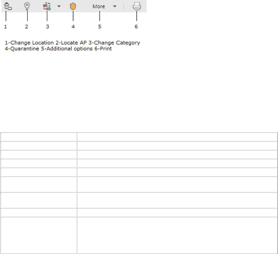
Devices
197
AirTight APs that form a wireless mesh network will always be categorized as Authorized APs only. You
cannot change the category of such AirTight APs. If APs from vendors other than AirTight are part of the
mesh network, you are allowed to change the category of these APs from authorized to any other
category.
The APs tab is divided horizontally into two panes. The upper pane shows a list of APs for the selected
location. The lower pane shows the AP properties related to the AP you select in the upper pane of the
APs tab. You can view a list of recently associated clients associated with the selected AP, in case of
authorized, rogue, external and uncategorized APs.
In case of authorized APs, you can also view AP utilization, AP associated clients, AP traffic, AP average
data rate in the lower pane.
Both active and inactive APs are visible in the APs tab. Inactive APs of some categories are visible in
specific deployments only.
A toolbar is seen between the two panes as shown in the figure below. You can perform various
operations related to the APs using the options present on the toolbar.
To perform any operation facilitated by the toolbar, you need to select an AP row in the upper pane.
Note: The options available to perform various operations depend on the role of the user that has logged
in.
Mesh APs are categorized as Authorized, by default. You cannot change the category of the mesh APs if
they are Airtight APs. You cannot quarantine, automatically ban these APs. Hence the options under
More in the toolbar are disabled for mesh APs.
You can change the category of mesh APs if the APs are provided by a vendor other than AirTight.
The following table provides a description of the fields seen in the upper pane of the APs tab.
Field
Description
Active Status
Indicates whether the AP is active or inactive.
RSSI
Observed RSSI (Received Signal Strength Indicator) value for the AP .
Name
User-defined name of the AP.
MAC Address
Unique 48-bit address of the AP/ 802.11 PHY modes used by the AP.
Channel
Channel number on which the AP operates. The channel is shown as
Dual for AP that operates on both 802.11a and 802.11b/g simultaneously.
Protocol
802.11 protocol used – 802.11a, 802.11b only, 802.11b/g, or
802.11a/b/g, with or without 802.11n or 802.11ac capability.
Clients
Number of active clients associated with the AP.
SSID
For an AP, it specifies the operating SSID, which is the unique identity
that prospective Clients use to recognize the network. When several
WLANs operate in the same space, SSID helps Clients in deciding which
one to join. However, SSID alone does not pro
vide any meaningful
security.

AirTight Management Console User Guide
198
Security
Security standard such as Open, WEP, WPA, 802.11i, or Unknown,
applied to the AP. This is derived from the template applied to the AP.
Location
Location of the AP.
Network
Network to which AP is connected.
Up/Down Since
Date and time since which the AP is up or down.
Networked Status
Indicates whether or not the AP is in the network.
Vendor
Name of the AP vendor.
Is Banned
Indicates if the AP is a banned AP.
Quarantine Status
Indicates if the AP is quarantined.
First Detected At
Date and time on which the AP was first detected.
Encryption
Encryption protocol used by the AP.
Troubleshooting
Indicates if troubleshooting is in progress for the AP.
MFP/11w
Indicates if MFP/11w is enabled on the AP.
Authentication
Authentication Protocol used by AP.
Classification
Classification of the AP.
Manually Classified
Indicates if the AP is manually classified.
View AP Properties
Select an AP and view its properties. Some AP properties are editable, others are not. To edit an AP
property, double-click it, edit it and save the new value.
The following table provides a field-wise description of the AP properties.
Field
Description
Name
Name of the AP.
Classification
Specifies whether the AP is categorized as Authorized,External,or Rogue.
Uncategorized indicates that the AP has not been categorized.
Location
AP location.
Is Placed
Specifies whether the AP has been placed on a layout for a location.
MAC Address
Unique 48-bit address of the AP/ 802.11 PHY modes used by the AP.
Protocol
Wireless protocol version used by the AP to provide wireless connectivity.
Capability
Operation mode capabilities of the device like 802.11n, 802.11ac, Super
AG, Turbo etc
SSID
SSID of the WLAN to which the AP is connected.
Is Guest
Specifies whether the AP is a guest AP or not.
Device Tag
Text that provides additional information about the AP; for example,
Hawaii Conference Room, Bldg 15 – Cubicle G2.
IP Address
IP address if the AP is authorized. The field is blank if the AP is rogue or
external.
Network
Network tag of the network to which the AP is connected. This value is
blank if the AP is not connected to a network.
Vendor Name
Name of the AP vendor.
First Detected At
Date and time when the AP was first detected by the system.
Up Since
Date and time since which the AP is up.
Channel
Channel number on which the AP operates.

Devices
199
Basic Link Rates
(Mbps)
Comma
-separated list of link rates supported by the AP.
Security
Security standard applied to the AP. This is derived from the template
applied to the AP.
Authentication
Procedure used by APs to verify the identity of a client.
Pairwise Encryption
Encryption used for unicast communication between the AP and a Client.
MULTIPLE is displayed, if 'For All BSSIDs' is selected in the MAC/Protocol
field.
Groupwise
Encryption
Specifies the encryption used for broadcast or multicast communication
from the AP. MULTIPLE is displayed, if For All BSSIDs is selected in the
MAC/Protocol field.
Beacon Interval
time interval, in millisecond,s between successive beacons of the AP.
802.11n Capability
This field is visible only if the selected AP is an 802.11n AP. 802.11n
capability of the AP. The field provides information about whether the AP
is compliant with early o
r standard implementations of the 802.11n
standard.
Channel Width
This field is visible only if the selected AP is an 802.11n AP or a 802.11ac
AP. It specifies whether an 802.11n AP is operating on 20 MHz or 40 MHz
channel width. 802.11n allows for the us
e of standard channel width of 20
MHz or double channel width of 40 MHz. 40 MHz channel width is
achieved by using two adjacent channels to send data simultaneously. In
case of 802.11ac capable AP, the possible values are 20 MHz, 40 MHz,
80 MHz, 160 MHz or 80+80 MHz.
Channel offset
This field is visible only if the selected AP is an 802.11n AP. It specifies
whether the adjacent channel used in 40 MHz operation is above or below
the primary channel for the selected 802.11n AP.
Data Rate
This field is visible only if the selected AP is an 802.11n AP or an
802.11ac AP. It specifies the highest 802.11n data rate or the
highest
802.11ac data rate of the selected active 802.11n AP or 802.11ac AP with
which it communicates with the client.
GI for 20 MHz
This field is visible only if the selected AP is an 802.11n AP. It specifies if
the AP is capable of using short guard interval for 20 MHz. The possible
values are 400 nanoseconds and 800 nanoseconds.
GI for 40 MHz
This field is visible only if the selected AP is an 802.11n AP. It specifies if
the AP is capable of using short guard interval for 40 MHz. The possible
values are 400 nanoseconds and 800 nanoseconds. This field is
applicable only if the channel width is 40 MHz or more.
802.11n MCS
supported
This field is visible only if the selected AP is an 802.11n AP. It specifies
the various Modulation and Coding Schemes (MCS) supported for
802.11n. The 802.11n standard defines a total of 77 MCS. Each MCS is a
combination of a certain modulation (for example,
BPSK, QPSK, 64-
QAM), coding rate (for example, 1/2, 3/4), guard interval (800 or 400 ns),
and number of spatial streams. Support for MCS 0
-15 is mandatory for
802.11n APs and support for MCS 0-7 is mandatory for 802.11n Clients.
Greenfield Mode
This field is visible only if the selected AP is an 802.11n AP. It specifies if
the AP is capable of working in the Greenfield mode. Greenfield mode is
an optional high
-throughput mode in the 802.11n standard, which is not
backward compatible with legacy (802.11a/b/
g) protocols and is expected
to provide maximum performance benefits of 802.11n.
802.11n Beam
forming Capability
This field is visible only if the selected AP is an 802.11n AP. It specifies if
the AP is capable of Beamforming. Beamforming is an RF transmi
ssion
method that helps in focusing the radiated RF energy directly at a

AirTight Management Console User Guide
200
receiving Client. This improves signal reception at the client and
consequently the throughput.
MFP/802.11w
Indicates if MFP/802.11w is enabled on the selected AP.
Quarantine Status
Quarantine status of the selected AP. Possible values are Not in
Quarantine, Quarantine Active, Quarantine Pending, DoS Quarantine on,
DoS Quarantine pending, Quarantine disabled.
Defending Sensor
Name
Name of defending sensor.
Quarantine Pending
Reason
Reason if quarantine is pending. Possible values are Device Inactive,
Device(s) outside the prevention range of all <device name> devices.,
Prevention capacity full at all <device name> within the prevention range,
Device operating Channel unknown, Quaran
tined Client currently not a
security threat, Error in selecting <device name> for prevention, No
suitable <device name> found for prevention, device channel not in
defend list of any <device name>, Wired side identity of the device not
available, waiting for <device name> acknowledgement, Unknown.
Tx STBC 802.11n
This field is visible only if the selected AP is an 802.11n AP. It indicates
support for transmission of PLCP protocol data units (PPDUs) using space
time block code (STBC).
'Yes'
indicates that transmission of PPDUs using STBC is supported.
'No' indicates that transmission of PPDUs using STBC is not supported.
Rx STBC 802.11n
This field is visible only if the selected AP is an 802.11n AP. It indicates
support for reception of PLCP protocol da
ta units (PPDUs) using space
time block code (STBC).
If this reception is supported, the number of
spatial streams supported is indicated. Upto 3 spatial streams are
supported for the 802.11n protocol.
802.11ac capability
This field is visible only if the selected AP is an 802.11ac AP. It indicates
whether the selected AP is 802.11ac capable.
'Yes' indicates that the AP is 802.11ac capable.
Supported Channel
width
This field is visible only if the selected AP is an 802.11ac AP. It indicates
the 160 and 80+80 MHz operation capability of the selected 802.11ac AP.
Possible values are 80 MHZ, 160 MHz, or 160 MHz and 80+80 MHz.
GI (80MHz)
This field is visible only if the selected AP is an 802.11ac AP. It indicates if
the 802.
11ac AP is capable of using short guard interval for 80 MHz.
The possible values are 400 nanoseconds and 800 nanoseconds. This
field is applicable only if the channel width is 80 MHz or more.
GI (160 MHz and
80+80 MHz)
This field is visible only if the selected AP is an 802.11ac AP. It indicates if
the802.11ac AP is capable of using short guard interval for 160 MHz and
80+80 MHz.
The possible values are 400 nanoseconds and 800 nanoseconds.
This
field is applicable only if the channel width is 160 MHz or 80+80 MHz.
Tx STBC 802.11ac
This field is visible only if the selected AP is an 802.11ac AP. It indicates
support for the transmission of at least 2x1 STBC. This field is specific to
802.11ac.
'Yes' indicates that the transmission of at least 2x1 STBC i
s supported.
'No' indicates that the tranmission of at least 2x1 STBC is not supported.
Rx STBC 802.11ac
This field is visible only if the selected AP is an 802.11ac AP. It indicates
support for the reception of
PLCP protocol data units (PPDUs) using
space time block code (STBC).
If this reception is supported, the number
of spatial streams supported is in
dicated. Upto 4 spatial streams are
supported for the 802.11ac protocol.
SU Beamformer
This field is visible only if the selected AP is an 802.11ac AP. It indicates

Devices
201
Capability
support for operation as a single user beamformer.
'Yes' indicates that the o
peration as a single user beamformer is
supported.
'No' indicates that the operation as a single user beamformer is not
supported.
SU Beamformee
Capability
This field is visible only if the selected AP is an 802.11ac AP. It indicates
support for operatio
n as a single user beamformee.
'Yes' indicates that the operation as a single user beamformee is
supported.
'No' indicates that the operation as a single user beamformee is not
supported.
MU Beamformer
Capability
This field is visible only if the selected AP is an 802.11ac AP. It indicates
support for operation as a multiuser beamformer.
'Yes' indicates that the operation as a multiuser beamformer is supported.
'No' indicates that the operation as a multiuser beamformer is not
supported.
MU Beamformee
Capability
This field is visible only if the selected AP is an 802.11ac AP. It indicates
support for operation as a multiuser beamformee.
'Yes' indicates that the operation as a multiuser beamformee is supported.
'No' indicates that the operation as a
multiuser beamformee is not
supported.
802.11ac MCS for
each Stream
This field is visible only if the selected AP is an 802.11ac AP. It specifies
the maximum 802.11ac Modulation and Coding Schemes (MCS)
supported for each supported Tx stream.
Number of Spatial
Streams
This field is visible only if the selected AP is an 802.11ac AP. It specifies
the number of Tx and Rx spatial streams supported by the AP.
Channel List
This field is visible only if the selected AP is an 802.11ac AP. It specifies
the list of channels in the operating band of the 802.11ac AP.
Mesh mode
Indicates whether mesh mode is enabled or disabled for the selected AP.
View Recently Associated Clients
Under Recently Associated Clients, you can view a list of clients that are recently associated to the
selected AP. The criterion for recent association is either 12 hours or the total number of clients (this is
the total number of associations in the system and not per device). The total number of associations
maintained by AirTight Management Console depends upon the number of AirTight devices connected to
the AirTight server. Client details such as Client Name, RSSI, IP address and Last Detected At are
displayed in the widget.
Note: Information related to recently associated clients is available in specific deployments only.
View AP Utilization
Under AP Utilization section, you can see a graphical representation of the percentage of AP utilization
over the last 12 hours. AP Utilization section is seen only for authorized APs. The Airtight device keeps a
track of the cumulative time occupancy as a percentage of the total scan time of the channel every 15
minutes.
AirTight Management Console User Guide
202
View AP Associated Clients
Under AP Associated Clients section, you can see a graphical representation of the clients associated
with the AP, over the last 12 hours. The AirTight device samples the number of client associations with
the AP every 15 minutes.
View AP Traffic
Under the AP traffic section, you can see a graphical representation of the AP traffic over the last 12
hours. AP Traffic section is seen only for authorized clients. AirTight device seeing the AP reports data
traffic sent and received by the AP every 15 minutes. The channel rotating AirTight device spends only a
percentage of the total time on any given channel. Hence this parameter typically underestimates the
actual traffic by a factor equal to the total number of channels scanned by the device radio. For example,
if the AirTight device scans 30 channels in all, the measured traffic would be 1/30th of the actual traffic.
However, if the traffic is bursty in nature, such straightforward scaling cannot be applied.
View AP Average Data Rate
Under AP Average Data Rate section, you can see a graphical representation of the average data rate in
Mbps of the AP, over the last 12 hours. AP Average Data Rate section is seen only for authorized APs.
AirTight device seeing the client keep track of the transmission rates of the data frames in the AP's BSS
and reports weighted average transmission rate over every 15 minutes.
View Devices Seeing AP
The Devices Seeing APs widget shows the AirTight devices in sensor mode that have detected the AP
selected in the upper pane.
To view the AirTight devices seeing the AP, do the following.
1. Go to Devices>APs tab.
2. Select the location.
3. Select the AP.
4. In the lower pane, navigate to the page with the Devices seeing AP widget to view a list of AirTight
devices seeing the selected AP.
View AP Events
To view the current AP events for the AP selected in the upper pane, do the following.
1. Go to Devices>APs tab.
2. Select the location.
3. Select the AP.
4. In the lower pane, navigate to the page with the Events widget to view a list of active events for the
selected AP.
Change AP Location
To change the location of an AP on the floor map, do the following.
1. Go to Devices>APs tab.
2. Select the location.
3. Select the AP whose location you want to change.
Devices
203
4. Click the Change location icon. The Select New Location dialog box appears.
5. Select the new location for the AP.
6. Click OK.
Locate AP
To locate an AP on the floor map, do the following.
1. Go to Devices>APs tab.
2. Select the location at which the AP is placed.
3. Select the AP.
4. Click the Locate icon to locate the AP on the location floor map.
Quarantine an AP
To quarantine an AP, do the following.
1. Go to Devices>APs tab.
2. Select the location at which the AP to quarantine exists.
3. Select the AP to quarantine.
4. Click the Move to Quarantine icon, and click Yes on the confirmation message to quarantine the AP.
Change AP Category
To change the AP category, do the following.
1. Go to Devices>APs tab.
2. Select the location where you want to change the AP category.
3. Select the check box for the AP whose category you want to change.
4. Click the Change category icon present on the toolbar.
5. Select the desired category from Authorized, External, Rogue, as the case may be.
Disable Auto Quarantine
1. Go to Devices>APs tab.
2. Select the location at which the AP is placed.
3. Select the AP and click More on the toolbar.
4. Click the Disable auto quarantine option, to disable auto quarantining of APs.
Add to banned list
To add an AP to the banned list, do the following.
1. Go to Devices>APs tab.
2. Select the.location at which the AP is placed.
3. Select the AP and click More on the toolbar.
4. Click the Add to banned list option to add the AP to the banned list.
Sort APs

AirTight Management Console User Guide
204
You can sort AP details on the columns in the upper pane of the APs tab. You can sort the APs in the
ascending or descending order.
1. Go to Devices>APs tab.
2. Select the location.
3. Point to the column in the upper pane on which you want to sort and click .
4. You can click the arrow again to reverse the sort order. The icon could be an up arrow or a down
arrow based on the current sort order.
Filter AP Details
You can choose the columns to be viewed or filter the AP information to be displayed on the UI based on
filter text matching the text in the selected column.
For example, if you want to view only the APs with WPA security, do the following.
1. Go to Devices>APs tab.
2. Select the location.
3. Point to Security in the upper pane,click and enter 'WPA' as the filter text.
4. Press the Enter key to view the APs with WPA security.
To choose the columns to be viewed, do the following.
1. Go to Devices>APs tab.
2. Select the location.
3. Point to any column name in the upper pane, click . A menu appears.
4. Point to Columns option in the menu and select the check boxes for the columns to be made visible
on the UI. Deselect the check boxes, if they are already selected, for the columns that you don't want
to view on the UI.
Search APs
You can search for an AP using the name of the AP, MAC address of the AP or SSID of the AP.
To search for an AP or APs, do the following.
1. Go to Devices>APs tab.
2. Select the location where you want to search APs.
3. Enter the name, MAC address or SSID of the AP in Quick Search box at the top right corner.
4. Press the Enter key. The AP or APs that match the search criteria is displayed in the upper pane.
Enable Pagination for AP Listing and Set Page Size
By default, the AP listing in the upper pane is presented in a grid. You can scroll down to the last AP row
in the upper pane without having to browse across pages. A paginated view is also available if you want
to view a page-wise list of APs. You can enable pagination for the APs that are visible to you and
configure the number of rows on each page in the upper pane.
To enable pagination, do the following.
1. Go to Devices>APs tab.
2. Click the icon seen on the right side of the tool bar. A message to confirm pagination for all
grids/listings on the UI appears.
Devices
205
3. Click OK. The pagination for AP listing is enabled. The pagination for all other grids such as AirTight
devices, clients, networks, events and AirTight Mobile clients is enabled as well. Note that this setting
is restricted to your login only and is not applicable to other users.
To set the page size, do the following.
1. Go to Devices>APs tab.
2. On the tool bar, click the down arrow next to the number of rows displayed to the left of the icon.
The options First Page and Set page size appear.
3. Click Set Page Size and enter the number of rows to be visible on each page.
4. Click OK.
You can browse through the paginated AP listing by clicking the (next page) and (previous page)
icons. To go to the first page, click the down arrow next to the number of rows on the page and select the
First page option.
Disable Pagination for AP Listing
If you have enabled pagination and want to disable it, you can restore the default view of having a
complete listing of all APs on a single page.
To disable pagination, do the following.
1. Go to Devices>APs tab.
2. Click the icon seen on the right side of the tool bar. A message to confirm disabling of pagination
for all grids/listings on the UI appears.
3. Click OK. The pagination for AP listing is disabled. The pagination for all other grids such as AirTight
devices, clients, networks, events and AirTight Mobile clients is disabled as well. Note that this setting
is restricted to your login only and is not applicable to other users.
Add Custom Filter
You can create custom filters and save them with the name of your choice. You can select the columns to
be viewed and can, optionally, set a filter on the data in the columns seen on AirTight Management
Console. You can save this filter with a name and can create multiple filters in this manner.
Note the following points when working with custom filters.
• Preferences for visibility of columns and sorting of column data are not saved in a custom filter. Only
the filter criteria is saved.
• Custom filters are user-specific. They are saved for the user who has defined the custom filter and is
not visible to any other user.
• An unsaved filter is indicated by an asterisk next to the filter name seen next to Filter on the tool bar.
• An unsaved filter is not saved if the user logs out without saving the filter.
To create a custom filter, do the following.
1. Go to Devices>APs.
2. Click the icon next to a column header. A list of options is displayed.
3. Point the mouse at the Filters option and enter the filter text for the column.
4. Click the icon next to Filter on the tool bar and click Save as. The Save as dialog box appears.
5. Enter the name of the filter and click OK. The custom filter is saved.
Edit Custom Filter

AirTight Management Console User Guide
206
To edit a custom filter, do the following.
1. Go to Devices>APs.
2. Click the icon next to Filter on the tool bar and select the required filter.
3. Click the icon next to a column header. A list of options is displayed.
4. Point the mouse at the Filters option and enter the filter text for the column or make changes to the
filter criteria as required.
5. Click the icon next to Filter on the tool bar and click Save. The modified custom filter is saved.
Delete Custom Filter
To delete a custom filter, do the following.
1. Go to Devices>APs.
2. Click the icon next to Filter on the tool bar and click the icon for the filter to delete. A message
asking you to confirm delete appears.
3. Click Yes to confirm deletion of the custom filter.
Print AP List for Location
You can print all the information seen for all APs in the upper pane. You can choose the columns to be
viewed on the UI by selecting them. The information seen in the upper pane is the information that will be
seen in the printout.
If pagination is enabled, the list of APs on the current page are printed. To print a list of all APs for a
location, you must go to each page and print the individual pages.
If pagination is disabled, only the list of APs visible on the UI is printed. This means that if there are 25
records of which only the first five have been presented on the UI, these five records are printed.
You must enable or disable pagination before you print.
To print the AP list for a location, do the following.
1. Go to Devices>APs tab.
2. Select the location for which you want to print the APs' list.
3. Select the type of APs for which you want to print the list.
4. Select the columns that you want in the printed list. Click any column name to select or deselect
columns.
5. Click the print icon. The print preview of the AP list appears.
6. Click Print to print the list.
Merge APs
The APs seen in the APs tab could be either a virtual AP or a physical AP. One or more virtual APs could
actually be a single physical entity. You can merge such virtual APs into a single AP through the APs tab
for better management. You can merge authorized APs only.
To merge authorized APs, do the following.
1. Go to Devices>APs tab.
2. Select the location for which you want to merge the APs.
3. Select two or more authorized APs to merge and click More on the toolbar.
4. Click the Merge option to merge the APs.
Devices
207
Split AP
One or more virtual APs that have been merged to form a single AP can be split back to the original
number of APs. The split option is available only if you select merged APs. As merging is available for
authorized APs only, the split AP option is also available for authorized APs only.
To split an authorized AP, do the following.
1. Go to Devices>APs tab.
2. Select the location for which you want to split a merged AP.
3. Select the merged AP to split and click More on the toolbar.
4. Click the Split option to split the APs.
Troubleshoot AP
You can troubleshoot APs using an AirTight device operating in sensor mode.
When you initiate troubleshooting, you must ensure that the AirTight device is reachable from the
computer used to launch the AirTight Management Console. If the AirTight device is busy in quarantine or
busy in troubleshooting, it will be not be able to troubleshoot the selected AP.
You can have an AirTight device (sensor) troubleshoot the AP in packet level mode or event level mode.
This sensor can troubleshoot in packet level mode using packet capture tools like Wireshark or any other
tool available to you.
You have two packet capture tool options – Wireshark and ‘Other’. Wireshark is available for free on the
Internet.
Alternatively, you can save the packet capture history to the AirTight server and download the history file
to save it for future reference. The packet capture history is saved as a .pcap file. This can also be viewed
using Wireshark or any other packet capture tool.
You cannot troubleshoot a merged AP with multiple BSSIDs. Troubleshooting of a single BSSID of a
merged AP can be done.
When a troubleshooting session is in progress, a notification regarding the active troubleshooting session
can be seen under Notifications (top right corner of the AirTight Management Console).
A troubleshooting session automatically times out or terminates after the specified timeout irrespective of
the activity.
IMPORTANT:Once the packet capture based troubleshooting session begins from the Console and the
packet capture tool is either interrupted or terminated (gracefully or abruptly), you have to first stop the
ongoing troubleshooting session from the Console either manually (if it is still going on) or ensure that the
session has indeed ended before you can start another packet capture session. Refer to the 'Stop
Troubleshooting' sub-section in this section to manually terminate a troubleshooting session.
You can then restart the fresh troubleshooting session from the Console.
If a troubleshooting session is in progress with a chosen tool (Wireshark or user specified tool), another
capture from the command prompt, using user specified capture parameters (viz. rpcap://sensor-ip/iface)
will not succeed from the same or another computer.
If you are an AirTight Cloud Services user, you can upload the packet capture file directly into WizShark.
You can then use WizShark to analyze the packet capture or trace files. Following are the prerequisites to
successfully upload the file to WizShark.
• You must have subscribed to the WizShark service.
• You must have upload privileges in WizShark.
AirTight Management Console User Guide
208
• The file size must not exceed the maximum file size prescribed by WizShark.
• When the file is uploaded, the total storage quota for your account must not be exceeded.
Troubleshoot AP in Packet Level Mode with Wireshark on local machine
To troubleshoot an AP in packet level mode, do the following.
1. Click Devices.
2. Select the APs tab.
3. Select the check box for the AP to troubleshoot.
4. Click the More>Packet Capture option on the tool bar. The Troubleshoot AP dialog box appears.
5. Select the check box for the sensor from the list of AirTight devices operating as sensors, using which
you want to troubleshoot the AP. The sensors seeing the device are sorted based on their availability
and signal strength.
6. Select the Live Packet Capture option under Troubleshooting Mode.
7. Select Streaming option as Wireshark on local machine.
8. Specify the time-out interval in Timeout. The default time-out for packet level troubleshooting mode is
5 mins. Minimum allowed value is 1 minute and maximum is 720 minutes for the time-out.
9. Select the type of packets you want to see while troubleshooting under Traffic Selection. If you want
to capture all packets visible to the troubleshooting AirTight device, select the All packets on the
channel option. If you want to view only packets from the AP visible to the troubleshooting sensor,
select the Only packets for the selected BSSID <BSSID value> option.
10. In the Protocol and Channel Selection section, select the protocols and channel for which you want
to troubleshoot. If you want to select a single channel, select the Select Channel option and specify
the channel number and Width (channel offset). By default, the protocol and channels are displayed
based on the device template applied to the troubleshooting sensor. You can select a different
protocol and/or channel, if required. Alternatively, you can select the Rotate on all Channels option,
to troubleshoot on all available channels.
11. Click Start Troubleshooting to start the troubleshooting. The sensor is enabled to capture live
packets.
12. Select an appropriate tool for live packet capture. If you don't have the tools already installed, you
can download Wireshark or any other tool.
13. To view the packet capture, open the command line interface of the operating system installed on
your computer and execute the command shown under Wireshark or any other packet capture tool.
The Troubleshooting in Packet Level Mode dialog box gives a guideline to the command to
execute for Wireshark..
Troubleshoot AP in Packet Level Mode to upload Packet History to AirTight
server
To troubleshoot an AP in packet level mode, do the following.
1. Click Devices.
2. Select the APs tab.
3. Select the check box for the AP to troubleshoot.
4. Click the More>Packet Capture option on the tool bar. The Troubleshoot AP dialog box appears.
5. Select the check box for the sensor from the list of AirTight devices operating as sensors, using which
you want to troubleshoot the AP. The sensors seeing the device are sorted based on their availability
and signal strength.
6. Select the Live Packet Capture option under Troubleshooting Mode.
7. Select Streaming option as Upload to Server.
8. Enter a suitable prefix for the file name in Filename Prefix. This helps you identify the
troubleshooting files when you download the packet history.
Devices
209
9. Specify the time-out interval in Timeout. The default time-out for packet level troubleshooting mode is
5 minutes. Minimum allowed value is 1 minute and maximum is 720 minutes for the time-out.
10. Select the packets you want to capture while troubleshooting, under Traffic Selection. If you want to
capture packets for all BSSIDs on the AirTight AP visible to the troubleshooting AirTight device, select
the Packets of all BSSID on this AirTight AP option. If you want to capture only the packets from
the AP visible to the troubleshooting sensor, select the Only packets for the selected BSSID<AP
MAC address> option.
11. Select the packet type. If you want to capture all packets, select the All option. If you want to capture
only specific packet types, select the filter option and then select the required data frames and/or
management frames to capture while troubleshooting.
12. In the Protocol and Channel Selection section, select the protocols and channel for which you want
to troubleshoot. If you want to select a single channel, select the Select Channel option and specify
the channel number and Width (channel offset). By default, the protocol and channels are displayed
based on the device template applied to the troubleshooting sensor. You can select a different
protocol and/or channel, if required. Alternatively, you can select the Rotate on all Channels option,
to troubleshoot on all available channels.
13. Click Start Troubleshooting to start the troubleshooting. The sensor is enabled to capture live
packets.
Troubleshoot AP in Event Level Mode
To troubleshoot an AP in event level mode, do the following.
1. Click Devices.
2. Select the APs tab.
3. Select the check box for the AP to troubleshoot.
4. Click the More>Packet Capture option on the toolbar. The Troubleshoot AP dialog box appears.
5. Select the check box for the sensor from the list of AirTight devices operating as sensors, using which
you want to troubleshoot the AP. The sensors seeing the device are sorted based on their availability
and signal strength.
6. Select the Generates Addtional Events for the device option under Troubleshooting Mode.
7. Specify the timeout interval in Timeout. The default timeout for event level troubleshooting mode is 2
mins. Minimum allowed value is 1 minute and maximum is 5 minutes for the timeout.
8. Select the packets you want to capture while troubleshooting, under Traffic Selection. If you want to
capture packets for all BSSIDs on the AirTight AP visible to the troubleshooting AirTight device, select
the Packets of all BSSID on this AirTight AP option. If you want to capture only the packets from
the AP visible to the troubleshooting sensor, select the Only packets for the selected BSSID <AP
MAC address> option.
9. In the Protocol and Channel Selection section, select the protocols and channel for which you want
to troubleshoot. If you want to select a single channel, select the Select Channel option and specify
the channel number and Width (channel offset). By default, the protocol and channels are displayed
based on the device template applied to the troubleshooting sensor. You can select a different
protocol and/or channel, if required. Alternatively, you can select the Rotate on all Channels option,
to troubleshoot on all available channels.
10. Click Start Troubleshooting to start the troubleshooting. The sensor generates events while
troubleshooting and these can be viewed under device listing as the latest events for the sensor.
Stop Troubleshooting
A troubleshooting session automatically times out or terminates after the specified timeout irrespective of
the activity. You can manually terminate a troubleshooting session.
To stop an active troubleshooting session manually, do the following.

AirTight Management Console User Guide
210
1. Click the Notifications icon at the top right corner. The active troubleshooting sessions are displayed
along with other notifications, if any.
2. Click the notification for active troubleshooting sessions. A list of sensor troubleshooting sessions is
displayed.
3. Select the check box for the troubleshooting session to terminate.
4. Click Stop. The troubleshooting session is terminated and a message indicating the termination of
the troubleshooting session is displayed. If the Upload to Server option has been selected as
Streaming option under Troubleshooting Mode, the packet capture history is uploaded to the
AirTight server.
Download Packet Capture
AirTight server maintains a packet capture history for the troubleshooting instances for a period of 30
minutes, after you stop troubleshooting.
You can download this history and save them for future reference. The packet captures are available in
.pcap format.
To download a packet capture file, do the following.
1. Select the required location from the location tree.
2. Click Devices.
3. Select the APs tab.
4. Click the More>Previous Packet Captures option on the tool bar. The Packet Capture dialog box
appears. The list of files is displayed with the file name, file size in KB, troubleshooting start time and
troubleshooting stop time.
5. Click the Download link for the packet capture file to download and select the path to store it. The
packet capture file is saved to the specified location.
If you are an AirTight Cloud Services user, and wish to upload the packet capture file to WizShark from
AirTight Management Console, click the View in WizShark link. The file is directly uploaded to WizShark
and WizShark opens up in a separate browser tab or browser window. You can then analyze the packet
capture file using WizShark.
Delete Packet Capture
AirTight server maintains a packet capture history for the troubleshooting instances for a period of 30
minutes, after you stop troubleshooting.
You can delete this packet capture history from the server. The packet capture files are available in .pcap
format.
To delete a packet capture file, do the following.
1. Select the required location from the location tree.
2. Click Devices.
3. Select the APs tab.
4. Click the More>Previous Packet Captures option on the tool bar. The Previous Packet Capture
dialog box appears. The list of files is displayed with the file name, file size in KB, troubleshooting
start time and troubleshooting stop time.
5. Select the check box for the log file to delete. You can select multiple files to delete at a time.
6. Click the icon. A message to confirm the deletion appears
7. Click Yes to confirm deletion of selected files.
Delete AP

Devices
211
You can delete one or more APs at the same location at a time. Active APs could be rediscovered by the
AirTight devices configured as sensors, and could reappear in the APs tab under the relevant category
based on the AP classification policy.
Inactive APs will be deleted and might not be visible until they are active.
To delete an AP, do the following.
1. Go to Devices>APs tab.
2. Select the location for which you want to delete the AP.
3. Select one or more APs to delete and click More on the toolbar.
4. Click the Delete option to initiate the delete operation for the AP. A message asking to confirm
deletion of AP appears.
5. Click Yes to confirm the deletion.
Monitor Networks
The Networks tab displays the list of networks, and the APs and sensors associated with these networks.
The Networks tab is divided horizontally into two panes.
A toolbar is seen between the upper and lower panes. This toolbar has icons to perform various
operations on the network selected in the upper pane.
The upper pane shows a list of networks detected at the selected location. The lower pane shows the
network properties related to the APs and sensors in the network selected in the upper pane of the
Networks tab.
The Network Properties: APs section is seen on page 1 of the lower pane in the Networks tab.
All APs associated with the network, and with the location including the sub locations under that location,
are seen in Network Properties: APs section.
The fields in the APs tab are the same as seen in Devices->APs tab. You can filter the APs seen based
on the AP categories, Authorized, Rogue, External, and Uncategorized. To see all types of APs, you can
select the All check box.
You can see a toolbar below the list of APs. Using this toolbar, you can perform all the operations related
to these APs similar to the operations you can perform in Devices>APs tab. To perform any operation on
the APs in the selected network, select the AP on which you want to perform the operation and click the
respective icon.
The Network Properties: Sensors section is seen on page 2 in the lower pane of the Networks tab.
The fields in the Sensors tab are the same as seen in Devices>AirTight devices tab.
Only currently active sensors in the network are seen in this section.
The following table provides description of the fields are seen on the Networks tab.
Field
Description
Name
Network name
Network Address
IP address of the network.
Location
Network Location
Monitoring sensor
Sensor monitoring the network
Gateway MAC
Gateway MAC address

AirTight Management Console User Guide
212
Exposed Since
Date and time since which the network is exposed.
Change location of network
Location of a network is same as location of the Sensor that reported the network first. If there are
multiple sensors connected to a network, location of such network is the nearest common location of all
reporting sensors.
To change the location of a network, do the following.
1. Go to Devices
2. Select the Networks tab.
3. Select the location at which the network has been detected.
4. Select the check box for the network whose location you want to change.
5. Click the Change location icon.
6. Select the new location on the Select New Location dialog that appears.
7. Click OK to move the network to the new location.
On selecting a new location, the network is seen under the new location.
Rename network
To rename a network, do the following.
1. Go to Devices
2. Select the Networks tab.
3. Select the check box for the network whose location you want to change.
4. Click the Rename Network icon.
5. Enter a new name in the Rename dialog that appears.
6. Click OK to rename the selected network. On selecting a new location, the network is seen under the
new location.
Enable Pagination for Network Listing and Set Page Size
By default, the network listing in the upper pane is presented in a grid. You can scroll down to the last
network row in the upper pane without having to browse across pages. A paginated view is also available
if you want to view a page-wise list of networks. You can enable pagination for the networks that are
visible to you and configure the number of rows on each page in the upper pane.
To enable pagination, do the following.
1. Go to Devices>Networks tab.
2. Click the icon seen on the right side of the tool bar. A message to confirm pagination for all
grids/listings on the UI appears.
3. Click OK. The pagination for network listing is enabled. The pagination for all other grids such as
AirTight devices, APs, clients, events and AirTight Mobile clients is enabled as well. Note that this
setting is restricted to your login only and is not applicable to other users.
To set the page size, do the following.
1. Go to Devices>Networks tab.
2. On the tool bar, click the down arrow next to the number of rows displayed to the left of the icon.
The options First Page and Set page size appear.
3. Click Set Page Size and enter the number of rows to be visible on each page.
4. Click OK.
Devices
213
You can browse through the paginated network listing by clicking the (next page) and (previous
page) icons. To go to the first page, click the down arrow next to the number of rows on the page and
select the First page option.
Disable Pagination for Network Listing
If you have enabled pagination and want to disable it, you can restore the default view of having a
complete listing of all networks on a single page.
To disable pagination, do the following.
1. Go to Devices>Networks tab.
2. Click the icon seen on the right side of the tool bar. A message to confirm disabling of pagination
for all grids/listings on the UI appears.
3. Click OK. The pagination for network listing is disabled. The pagination for all other grids such as
AirTight devices, APs, clients, events and AirTight Mobile clients is disabled as well. Note that this
setting is restricted to your login only and is not applicable to other users.
Add Custom Filter
You can create custom filters and save them with the name of your choice. You can select the columns to
be viewed and can, optionally, set a filter on the data in the columns seen on AirTight Management
Console. You can save this filter with a name and can create multiple filters in this manner.
To create a custom filter, do the following.
1. Go to Devices>Networks.
2. Select the location for which you want to create the custom filter.
3. Click the icon next to a column name. A list of options is displayed.
4. Point the mouse at the Columns option and select the check boxes for the columns to view.
5. Click the column name and select Sort Ascending option or Sort Descending option if you want to
sort the column data.
6. If you want to filter the data seen in the columns, click the icon next to a column name, select the
check box for the Filters option. Now enter the filter text for the column.
7. Click the icon next to Filter on the tool bar and click Save as. The Save as dialog box appears.
8. Enter the name of the filter and click OK. The custom filter is saved.
Edit Custom Filter
To edit a custom filter, do the following.
1. Go to Devices>Networks.
2. Select the location for which you want to edit the custom filter.
3. Click the icon next to Filter and select the required filter.
4. Make changes to the filter as required.
5. Click the icon next to Filter and and click Save. The modified custom filter is saved.
Delete Custom Filter
To delete a custom filter, do the following.
1. Go to Devices>Networks.
2. Select the location for which you want to delete the custom filter.
3. Click the icon next to Filter and click the icon for the filter to delete. A message asking you to
confirm delete appears.

AirTight Management Console User Guide
214
4. Click Yes to confirm deletion of the custom filter.
Print Network List for Location
You can print all the information seen for all networks in the upper pane for the selected location. You can
choose the columns to be viewed on the UI by selecting them. The information seen in the upper pane is
the information that will be seen in the printout.
If pagination is enabled, the list of networks on the current page is printed. To print a list of all networks
for a location, you must go to each page and print the individual pages.
If pagination is disabled, only the list of networks visible on the UI is printed. This means that if there are
25 records of which only the first five have been presented on the UI, these five records are printed.
You must enable or disable pagination before you print.
To print the AirTight devices list for a location, do the following.
1. Click Devices and then click the Networks tab.
2. Select the location for which you want to print the networks list.
3. Select the columns that you want in the printed list. Click any column name to select or deselect
columns.
4. Click the print icon. The print preview of the networks list appears.
5. Click Print to print the networks list.
Change Network Type
When you upgrade to release 7.1 Update 3 of the AirTight Management Console, all the networks are
marked as Cardholder Data Environment (CDE) networks, by default. If a network displayed in the
Networks tab does not possess or transmit credit card data, you can change the network type to non-
CDE.
Similarly, you can change a non-CDE network to a CDE network.
You can select multiple networks of the same type at a time and mark them as non-CDE or CDE, as
required.
To change the network type of a network, do the following.
1. Go to Devices
2. Select the Networks tab.
3. Select the check box for the network you want to mark as CDE or non-CDE.
4. Click the down arrow next to the icon on the toolbar. Select CDE or non-CDE as the case may
be. A confirmation message appears.
5. Click Yes on the confirmation message to change the network type.
The network type is changed and the new network type appears under the Network type column.
Delete Network
To delete a network from the Networks tab, do the following.
1. Go to Devices
2. Select the Networks tab.
3. Select the check box for the network you want to delete.
4. Click the Delete Network icon.
5. Click Yes on the Confirm dialog that appears on clicking the Delete Network icon.
215
Manage Locations and Location Layout
In AirTight Management Console, you can have a graphical representation of the placement of locations
and devices with respect to one another for the given location. This is called a location layout. Layout for
a location floor represents a floor plan. Similarly, the layout for a location folder could represent the
geographical placement of the sub-locations.
By looking at a location layout, you will also be able to figure out the placement of each device on the
floor plan, and the placement of related locations with respect to one another. You can pan across the
location layout to have a better view of the entire location layout.
Navigate to Locations page to manage layouts for the selected location. You can have a layout defined
for each location folder and location floor. You can then place the sub-locations, that is, the location
folders on the layouts for the location folders. Similarly, you can place devices on the layouts for the
location floors.
Define Location Tree
Click Locations to view the Locations page.
The location tree is seen on the left of the page. The layout is configured on the right side of the page.
The location tree comprises location folders and location floors.
Location folders represent organizational components such as buildings, cities, or countries.
Location floors represent component details such as a floor in a building. For example, Hawaii
Conference Room, Bldg 15–Cubicle G2, or Executive Area.
The default location folder of the root location is the Unknown folder. You can rename the Unknown
folder. You cannot create, delete, move, or add a location to the Unknown folder. When the location tag
of a location-aware device is not known or cannot be determined, it is tagged to the Unknown folder. By
default, the Unknown folder inherits all the policies except the Device Classification and Prevention
Policies from the root location. You can customize these policies.
The following figure shows the location tree. Click the various buttons as indicated in the 'Manage
Locations' figure below, to add, rename, move and delete locations.
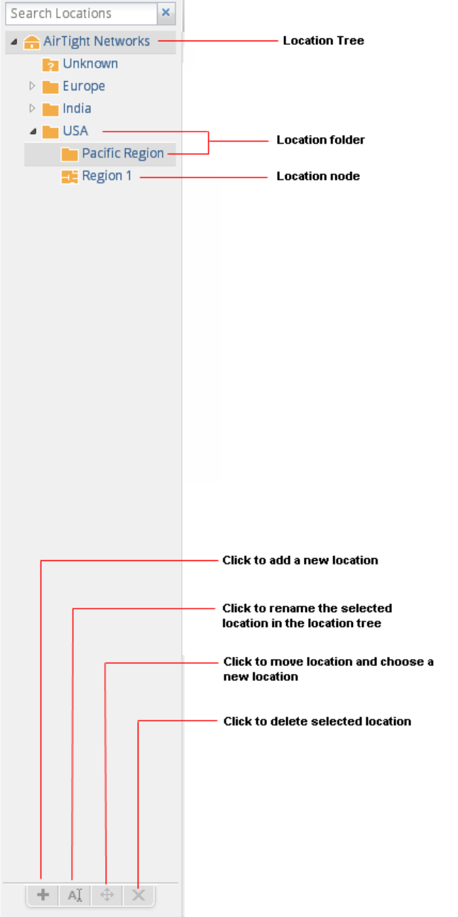
AirTight Management Console User Guide
216
Manage Layout
217
You can select a location folder or a location floor and add a layout to it. A layout for a location folder
could be a geographical map, while a layout for a location floor could be a floor map. You can add
location folders and location floors to the layout for a location folder. You can add devices, configured to
work with AirTight Management Console, to the layout for location floors. You can add notes to the
locations and devices on layouts to further explain the location or device placement or any other matter
related to the location layout.
You can also view a pictorial representation of the mesh wireless network topology in the locations layout.
You must be logged in as an administrator to make add or make changes to the location layout for a
location folder or location node.
If you are logged in to the parent server of a server cluster as a superuser, you can change the layout of
any of the locations or servers in the server cluster.
Add Location
You can represent buildings, geographical locations using location folders. You can represent floors or
levels in a building using a location floor. You can add one or more location folders under the root location
or under other location folders. You can add one or more location floors under a location folder. You
cannot add a location folder or a location floor to the Unknown folder. You cannot add a location floor
under a location floor.
To add a location folder, do the following.
1. Go to Locations. In the location tree, you will see the root location labelled Locations with the sub-
folder Unknown.
2. Select the location under which you want to add the location folder.
3. Click the add icon (plus sign) seen below the location tree. The Add New Location dialog box
appears.
4. Select Location Type as Folder
5. Enter the name of the location in Location Name.
6. Select the appropriate time zone for the location from Time Zone. Selecting the correct time zone is
essential for accurate analytics generation.
7. Click OK. The location folder is added under the selected location.
To add a location floor, do the following.
1. Go to Locations. In the location tree, you will see the root location labelled Locations with the sub-
folder Unknown.
2. Select the location under which you want to add the location floor.
3. Click the add icon (plus sign) seen below the location tree. The Add New Location dialog box
appears.
4. Select Location Type as Floor.
5. Enter the name of the location in Location Name.
6. Click OK. The location floor is added under the selected location folder.
Edit Location
To edit a location folder or location floor, do the following.
1. Go to Locations.
2. Select the location folder or location floor to edit.
3. Click the edit icon (letter 'A') seen below the location tree. The Edit Location dialog box appears.
AirTight Management Console User Guide
218
4. Make the required changes.
5. Click OK.
Move Location
To move a location folder or location floor from one location to another, do the following.
1. Go to Locations.
2. Select the location folder or location floor to move.
3. Click the move icon (cross arrows) seen below the location tree. The Select Destination Location
dialog box appears.
4. Select the destination location.
5. Click OK. The location folder or location floor is moved to the new destination.
Delete Location
To delete a location folder or a location floor from the location tree, do the following.
1. Go to Locations.
2. Select the location folder or location floor to delete.
3. Click the delete icon (delete symbol) seen below the location tree. A message to confirm deletion
appears.
4. Click Yes to confirm deletion.
Search Locations
To search for a location, do the following.
1. Go to Locations.
2. Enter the text substring matching the name of the location folder or location floor in Search
Locations, seen above the location tree.
3. Press the Enter key to view all the location folders and location floors containing this search criterion.
The matching locations are seen with their location hierarchy in the location tree when searched
using the text string or substring.
To clear the location search, click the x seen next to Search Locations.
Add Layout
When there are no layouts defined for the selected location, you will see a Configure Location Layout
hyperlink on the Locations tab with a notification that no layouts are present for the location. Once the
layout image is added, you can add locations, notes to the layout image for a location folder. Similarly,
you can add devices and notes to the layout image for a location floor.
You can show the location list and hide the location list by clicking the Show Location List and Hide
Location List links respectively.
You can select a location from the location list and drag it to place on the desired position on the layout.
Similarly, you can select the location on the layout and drag it back on the location list to remove the
location from the layout.
IMPORTANT: Ensure that you have defined the location tree before you add location layouts. Without
this, you will not have any locations to place on the layout for location folders.
Manage Layout
219
To add a layout to a location folder, do the following.
1. Go to Locations.
2. From the location tree, select the location folder for which you want to add a layout. When no layout
is attached to a location, a message indicating this is seen, along with the Configure Location
Layout link.
3. Click Configure Location Layout link.
4. Click the Add Layout link.
5. Click Choose File. The file open dialog box is displayed.
6. Browse to the desired layout image path to be added and click Open. The image is attached to the
location. You will be able to the see the list of locations.
7. Drag and drop locations from the location list to the desired position on the layout. If the location list is
not visible, click Show Location List to view a list of available locations.
8. Click Save to save the layout.
For individual floors in a location, you can add either a layout image with its dimensions to a location floor
or a .spm file that has been exported from AirTight Mobile. In case you specify a layout image, you must
also specify the dimensions of the image, that is the width, length and unit of measurement.
To add a layout using a layout image to a location floor, do the following.
1. Go to Locations.
2. From the location tree, select the location floor for which you want to add a layout. When no layout is
attached to a location, a message indicating this is seen, along with the Add Layout link.
3. Click the Add Layout link. The Add Layout dialog box appears.
4. Click Choose File seen next to Layout Image. The file open dialog box is displayed.
5. Browse to the desired layout image path to be added and click Open. The image is attached to the
location.
6. Select the unit of measurement of the dimensions in Unit.
7. Specify the width of the layout image in Width.
8. Specify the length of the layout image in Length.
9. Drag and drop devices from the device list to the desired position to place them on the layout. If the
device list is not visible, click Show Device List to view a list of available devices.
10. Click Save to save the layout.
To add a layout using a .spm file to a location floor, do the following.
1. Go to Locations.
2. From the location tree, select the location floor for which you want to add a layout. When no layout is
attached to a location, a message indicating this is seen, along with the Add Layout link.
3. Click the Add Layout link. The Add Layout dialog box appears.
4. Click Choose File seen next to Layout SPM. The file open dialog box is displayed.
5. Browse to the desired layout image path to be added and click Open. The image is attached to the
location.
6. Drag and drop devices from the device list to the desired position to place them on the layout. If the
device list is not visible, click Show Device List to view a list of available devices.
7. Click Save to save the layout.
Edit Layout
You can replace the layout image for a location folder or a location floor. You must then place the
locations or devices again on the new layout image. You can also rearrange the locations or devices on a
location layout without changing the layout image or .spm file attached to the location folder or location
floor.
AirTight Management Console User Guide
220
To edit a layout, do the following.
1. Go to Locations.
2. From the location tree, select the location folder or floor for which you want to edit the layout.
3. Click the Edit Layout link.
4. Make the necessary changes.
5. Click Save to save the changes to the layout.
Delete Layout
You can delete a location layout attached to a location folder or a location node. When you delete a
layout, all the device placement is undone.
To delete a location layout attached to a location folder or a location floor, do the following.
1. Go to Locations.
2. From the location tree, select the location folder or floor for which you want to delete the layout.
3. Click the Delete Layout link. You will be asked to confirm the deletion of the layout.
4. Click Yes to confirm deletion of layout. The layout is deleted and no devices are seen.
Show / Hide Location List
The label of the hyperlink toggles between Hide Location List and Show Location List, depending on
whether the location list is visible on the layout or not visible on the layout.
To show/hide location list, do the following.
1. Go to Locations.
2. From the location tree, select the location folder or location floor.
3. Click the Show Location List hyperlink that appears above the layout, to show the location list on the
layout. If the location list is already visible and you want to hide it, click the Hide Location List
hyperlink.
Show/Hide Devices on Location Layout
To view the list of devices for a location, do the following.
1. Go to Locations.
2. From the location tree, select the location folder or location floor. The label of the hyperlink toggles
between Hide Device List and Show Device List, depending on whether the device list is visible on
the layout or not visible on the layout.
3. To show the device list, click Show Device List link. To hide the device list, click the Hide Device
List link.
Place Devices/Locations on Location Layout
Locations can be placed on the layout for a location folder. Devices can be placed on the layout for a
location floor.
Manage Layout
221
You must add a layout to a location folder to be able to place locations on to the layout for the location
folder. Similarly, you must add a layout to a location floor to be able to place devices on to the layout for
the location floor.
You cannot place a server on location layouts in case you are logged in to and working on a parent server
in a server cluster.
To place a location on the layout for a location folder, do the following.
1. Go to Locations.
2. From the location tree, select the location folder.
3. Select a location from the locations list, and drag and drop the location to the desired position on the
location layout.
4. Click Save to save the placement of locations on the location layout.
To place a device on the layout for a location floor, do the following.
1. Go to Locations.
2. From the location tree, select the location floor. The location layout for the location floor is seen with
the locations placed on it.
3. Select the device from the device list, and drag and drop it to the desired place on the location layout.
4. Click Save to save the placement of devices on the location layout.
Remove Devices/Locations from Location Layout
You can remove one or more locations placed on a layout for a location folder. Similarly, you can remove
one or more devices placed on a layout for a location floor.
To remove a location from the layout for a location folder, do the following.
1. Go to Locations.
2. From the location tree, select the location folder. The location layout is seen with the locations placed
on it.
3. Hover the mouse on the location to be deleted from the location layout. A bin icon appears to the right
of the device.
4. Click the bin icon to remove the device from the location layout.
5. Click Save to save the changes.
To remove a device from the layout for a location floor, do the following.
1. Go to Locations.
2. From the location tree, select the location floor. The location layout is seen with the devices placed on
it.
3. Hover the mouse on the device to be deleted from the location layout. A bin icon appears to the right
of the device.
4. Click the bin icon to remove the device from the location layout.
5. Click Save to save the changes.
View RF Coverage / Heat Maps
You can view the heat map or RF coverage for a location floor by selecting AP Coverage or Sensor
Coverage option available under Heat Map View.
• AP Coverage View
• Sensor Coverage View
• AP Link Speed
• AP Channel Coverage
AirTight Management Console User Guide
222
The AP Coverage View enables you to view an 802.11 RF coverage map based on the dbm at each point
on the layout. This information is useful to find out available signal strength at each point.
The Sensor Coverage View enables you to view the detection and prevention zones of visibility for
selected Sensors. Detection Range is the area over which Sensors can reliably detect wireless activity of
devices operating at a power level greater than the value set in the Transmit Power slider. The Intrusion
Detection Display Threshold determines the threshold for this range.
Prevention Range is the area over which Sensors can prevent unauthorized wireless activity. The
Intrusion Prevention Display Threshold determines the threshold for this range.
The AP Channel View enables you to view all the 802.11 channels available for connection at each point
on the floor. It helps in preventing potential channel interference scenarios.
The AP Link Speed View enables you to view the maximum downlink rate with which a Client at a
particular point can connect to an AP on the floor.
The color-coding scheme used enhances the readability of the map.
To view a live RF coverage map for a location floor, Authorized APs and Sensors must be placed on the
location layout of the location floor.
View AP Coverage
To view AP coverage , do the following.
1. Go to Locations.
2. From the location tree, select the location floor for which you want to see the AP coverage view.
3. Place devices on the location layout if they are not already placed.
4. Click the AP Coverage link under Heatmap Views.
5. Select 802.11a if you want to view APs operating in 802.11a mode.
6. Select 802.11b/g if you want to view APs operating in 802.11b/g mode.
7. Select the appropriate resolution in Resolution. You can see the AP coverage view.
View AP Coverage by RSSI Value
You can select the RSSI value to view the AP coverage provided by all authorized APs placed on the
location map. It helps you understand the boundaries of RSSI coverage with different threshold values.
To view AP coverage by RSSI value, do the following.
1. Go to Locations.
2. From the location tree, select the location floor for which you want to see the AP coverage view.
3. Place devices on the location layout if they have not already been placed.
4. Click the AP Coverage link under Heatmap Views.
5. Select 802.11a if you want to view APs operating in 802.11a mode.
6. Select 802.11b/g if you want to view APs operating in 802.11b/g mode.
7. Select the RSSI value check box and move the slider to the right or left to the required RSSI value.
The area covered by the AP for the selected RSSI is seen on the location map.
View Sensor Coverage
To view sensor coverage view, do the following.
Manage Layout
223
1. Go to Locations.
2. From the location tree, select the location floor for which you want to see the Sensor coverage view.
3. Place devices on the location layout if they are not already placed.
4. Click the Sensor Coverage link under Heatmap Views.
5. Select 802.11a if you want to view APs operating in 802.11a mode.
6. Select 802.11b/g if you want to view APs operating in 802.11b/g mode.
7. Select the appropriate resolution in Resolution. You can see the sensor coverage view.
8. Select Detection if you want to view the detection zone of visibility of the AirTight devices functioning
as sensors.
9. Select Prevention if you want to view the prevention zone of the AirTight devices functioning as
sensors.
10. Select the transmit power. You can see the sensor coverage view.
View AP Link Speed
To view AP link speed, do the following.
1. Go to Locations.
2. From the location tree, select the location floor for which you want to see the AP coverage view.
3. Place the devices on the location layout if they are not already placed.
4. Click the AP Link Speed link under Heatmap Views.
5. Select 802.11a if you want to view APs operating in 802.11a mode.
6. Select 802.11b/g if you want to view APs operating in 802.11b/g mode.
7. Select the appropriate resolution in Resolution. You can see the AP link speed.
View AP Channel Coverage
To view AP channel coverage , do the following.
1. Go to Locations.
2. From the location tree, select the location floor for which you want to see the AP coverage view.
3. Place the devices on the location layout if they are not already placed.
4. Click the AP Channel Coverage link under Heatmap Views.
5. Select 802.11a if you want to view APs operating in 802.11a mode.
6. Select 802.11b/g if you want to view APs operating in 802.11b/g mode.
7. Select the appropriate resolution in Resolution. You can see the AP channel coverage.
Calibrate RF Views
Calibration helps in tuning RF parameters used by AirTight WIPS to compare the AP and Sensor
predictions with the actual observations. You can view a graph of the Predicted vs. Observed Signal
Strengths when you calibrate an RF view.
AirTight WIPS has a robust calibration technique that also allows manual intervention in case of
discrepancy. To improve predictions, you can fine tune the minimum signal decay exponent and
maximum signal decay exponent.
Minimum signal decay exponent specifies the amount of signal loss that is acceptable for regions close to
the transmitter (Sensor). Maximum signal decay exponent specifies the amount of signal loss that is
acceptable for regions away from the transmitter. Signal loss is directly proportional to the signal decay
exponents.
IMPORTANT: The Predicted value curve should overlap the Observed value curve as much as possible.

AirTight Management Console User Guide
224
When you change the Minimum Signal Decay exponent, Maximum Signal Decay exponent, Signal Decay
Slope (Beta), and Signal Decay Inflection (Alpha) the RF view and location tracking for unobstructed
regions is affected. In the obstructed regions, only Location Tracking is affected, RF view is not affected.
When you calibrate manually, the graph is automatically updated.
To calibrate RF views automatically, do the following.
1. Go to Locations.
2. From the location tree, select the location for which you want to calibrate RF views.
3. Generate the RF Coverage/heatmap using the steps explained in the View RF Coverage/Heat Maps
section
4. Clicking the Calibration link. The Calibration dialog box appears.
5. To calibrate automatically, click Calibrate under Automatic Calibration. The graph is updated when
you click Calibrate.
6. To calibrate manually, change the values of the Signal Decay Slope (Beta) and the Signal Decay
Inflection (Alpha). The system uses these parameters when computing the RF and defines the region
around the transmitter that is unobstructed.
7. Adjust the confidence.
8. Click OK or Apply to complete calibration if you have adjusted the parameters manually such that the
two curves are parallel (but not coinciding).
Note: You can change the intrusion detection display threshold and the intrusion prevention display
threshold from Configuration>System>Advanced Settings>Live RF View Settings.
Zoom in / Zoom out Layout
The Zoom slider is to the left of the Locations page. Move the Zoom slider up, to zoom in the layout.
Move the Zoom slider down, to zoom out the layout.
Select an appropriate resolution for rendering of heat maps. A lower resolution would mean a much faster
rendering, although with a high pixelization effect. High resolution would mean a much slower rendering
due to a large number of pixel cells for which values are being calculated. You can zoom in to a maximum
of 400% of the actual size. You can zoom out to a minimum of 25% of the actual size of the layout image.
Adjust the Layout Opacity
Move the Opacity slider to the right and left to adjust the opacity of the layout. This slider is on the top
right side of the Locations page.
• Decrease the image opacity to comprehend the RF coverage in a better way.
• Increase the image opacity to pinpoint exact device placement information.
Add Note
You can add notes to the location layout. These notes could be additional explanatory text or comments
related to the devices or the layout, in general.
To add a note to a location layout, do the following.
1. Go to Locations.
2. Select the desired location. Ensure that the layout has been added. If the layout is not added, add a
layout first.
Manage Layout
225
3. Click the Add Note link.
4. Enter the name of the note.
5. Enter the description of the note.
6. Click OK. A note is created. The note moves with the mouse.
7. Point the mouse to the desired position on the layout.
8. Click the mouse to place the note at that position on the layout.
Edit Note
To edit a note placed on the location layout, do the following.
1. Go to Locations.
2. Select the location where the note to be edited exists.
3. Hover the mouse over the note to be edited. You will see a pencil icon.
4. Click the pencil icon to edit the note.
5. Make the required changes in the name and/or description.
6. Click OK to save the changes.
Move Note
You can move an existing note to another position on the location layout.
To move a note from one position on a layout to another position the same layout, do the following.
1. Go to Locations.
2. Select the location on which the notes to move have been placed.
3. Drag and drop the note using the mouse to the required position on the location layout. The note is
moved to the new position.
Hide Notes
You can hide existing notes that have been placed on a location layout.
To hide existing notes, do the following.
1. Go to Locations.
2. Select the desired location on which the notes are placed.
3. Click Hide Notes link to hide the notes.
Show Notes
You can bring back the hidden notes on to a location layout.
To show existing notes, do the following.
1. Go to Locations.
2. Select the desired location on which the notes are placed.
3. Click Show Notes link to hide the notes.
AirTight Management Console User Guide
226
View Mesh Topology
On the Locations page, you can see a pictorial representation of the active AirTight devices functioning
as mesh APs. You can view the placement of the root and non-root mesh APs connected to each other to
form a wireless mesh network.
To view mesh topology, do the following.
1. Go to Locations.
2. Click the View Mesh Topology link. The mesh wireless network of APs is seen.
Note: It is the responsibility of the system/network administrator to ensure that mesh APs have been
properly configured. The Locations page merely displays the mesh topology based on the configuration
of the AirTight devices as mesh APs.
Hide Mesh Topology
You can hide the mesh topology after taking a look at it on the location layout.
To view mesh topology, do the following.
1. Go to Locations.
2. Click the Hide Mesh Topology link. The graphical representation of mesh wireless network of APs is
hidden when the link is clicked.
227
View and Manage Events
The Events page provides information about events generated in the system. On this page, you can
view, filter, locate, acknowledge, mark as read or unread, and toggle the state of the event’s participation
in vulnerability computation. You can also print the list of events seen at a location.
AirTight WIPS classifies events into the following types - Security, System, and Performance.
Security events are related to wireless security threats. For instance, if a rogue AP tries to access the
network,a security event is generated.
Security events are further categorized based on the wireless security threats. The categories of security
events are as follows.
• Events generated by rogue APs.
• Events generated by misconfigured APs.
• Events generated by misbehaving clients.
• Events generated by ad hoc networks.
• Events generated due to man-in-the-middle attacks.
• Events generated due to DoS (denial of service) attacks.
• Events generated due to MAC spoofing.
• Events generated due to prevention.
• Events generated due to wireless reconnaisance.
• Events generated due to cracking of the wireless network.
System events indicate the health of the system. They are further categorized as based on the events
generated by the sensor, the AirTight WIPS server and troubleshooting events.
Performance events indicate wireless network performance problems. They are further categorized on
the basis of bandwidth, configuration, coverage, and interference. These can be used to understand
problems related to the wireless network performance.
The Events page is divided into two panes. The upper pane shows a list of events for the selected
location. The lower pane shows the details of the sub-events, devices in the event and sub-event that are
related to the event you select in the upper pane of the Events page. A maximum of 50 sub-events per
event are presented in specific deployments. Some deployments can present only upto 25 sub-events for
an event.
When you click a device in the Devices in Selected sub-event widget, you can get more information about
the device. This device information is available in specific deployments only.
There is a toolbar between the upper pane and the lower pane. It contains icons to perform various event-
related operations such as change location of events, change vulnerability status of events, delete
events, print events etc.
The following table describes the event-related fields seen in the upper pane of the Events page.
Field
Description
ID
System generated Event ID for the event.
Event Severity
Severity of the event indicated by icons. Severity could be high, medium
or low.
Event Activity Status
Event status indicated by icons. The possible values are live,
instantaneous, updated, expired.
Details
Event description.

AirTight Management Console User Guide
228
Category
Event category.
Location
Location at which event has occurred.
Start Time
Time at which the event has started.
Event Read Status
Indicates if the event is read, unread, acknowledged or
unacknowledged.
Event Vulnerability Status
Indicates the event vulnerability.
Event Type
Type of event. The type is indicated by icons. The possible values are
security, system, performance.
Stop Time
Time at which the event has stopped.
View Events for Location
You can view the events at the selected location (and its child locations) based on their category. You can
filter out the events based on their category and sub-category.
To view events for a location, do the following.
1. Go to Events.
2. Select the location for which you want to view events.
3. Select the Security check box to view events that indicate security vulnerability or breach in your
network. You can view or filter out the security events by selecting or deselecting the check boxes for
the respective security events. Click the down arrow adjacent to the text 'Security' to show a list of
security events.
4. Select the System check box to view the events that indicate system health. You view or filter out the
system events based on its type, by selecting or deselecting the check boxes for the respective
system events. Click the down arrow adjacent to the text 'System' to show a list of system events.
5. Select the Performance check box to view the events that indicate wireless network performance
problems. You view or filter out performance events based on its type, by selecting or deselecting the
check boxes for the respective performance events. Click the down arrow adjacent to the text
'Performance' to show a list of performance event types.
Note: If you are viewing the root location on a parent server in a server cluster, you are presented with an
aggregation of all events on the child and parent servers. Currently, there is no mechanism in place to
view the events belonging solely to the parent server.
View Deleted Events for Location
To mark an event for deletion, do the following.
1. Go to Events.
2. Select the location for which you want to view deleted events.
3. Click More in the toolbar and select the Show deleted events option. The event is marked for
deletion.
Change Event Location
To change the location of an event, do the following.
1. Go to Events.
2. Select the location at which the event has occurred.
Events
229
3. Select the check box for the event for which you want to change the location.
4. Click the change location icon. The Select Location dialog box appears.
5. Select the new location and click OK. The event is moved to the new location.
Acknowledge Event
To acknowledge an event, do the following.
1. Go to Events.
2. Select the location for which you want to acknowledge an event.
3. Select the check box for the event for which you want to turn off the vulnerability status.
4. Click the turn off vulnerability icon to turn off the vulnerability of an event.
Turn on Vulnerability Status for Event
To turn on the vulnerability status for an event, do the following.
1. Go to Events.
2. Select the location for which you want to change the event vulnerability status.
3. Select the check box for the event for which you want to turn on the vulnerability status.
4. Click the turn on vulnerability icon to turn off the vulnerability of an event.
Turn off Vulnerability Status for Event
To turn off the vulnerability status for an event, do the following.
1. Go to Events.
2. Select the location for which you want to change the event vulnerability status.
3. Select the check box for the event for which you want to turn off the vulnerability status.
4. Click the turn off vulnerability icon to turn off the vulnerability of an event.
Mark Event as Read
To mark an event as read, do the following.
1. Go to Events.
2. Select the location for which you want to mark an event as read.
3. Select the check box for the event to mark as read.
4. Click More in the toolbar and select the Mark as read option. The event is marked as read.
Mark Event for Deletion
To mark an event for deletion, do the following.
1. Go to Events.
2. Select the location for which you want to delete an event.
3. Select the check box for the event to mark for deletion.
4. Click More in the toolbar and select the Mark for delete option. The event is marked for deletion.
AirTight Management Console User Guide
230
Enable Pagination for Event Listing and Set Page Size
By default, the event listing in the upper pane is presented in a grid. You can scroll down to the last event
row in the upper pane without having to browse across pages. A paginated view is also available if you
want to view a page-wise list of events. You can enable pagination for the events that are visible to you
and configure the number of rows on each page in the upper pane.
To enable pagination, do the following.
1. Go to Events.
2. Click the icon seen on the right side of the tool bar. A message to confirm pagination for all
grids/listings on the UI appears.
3. Click OK. The pagination for event listing is enabled. The pagination for all other grids such as
AirTight devices, APs, clients, networks and AirTight Mobile clients is enabled as well. Note that this
setting is restricted to your login only and is not applicable to other users.
To set the page size, do the following.
1. Go to Events.
2. On the tool bar, click the down arrow next to the number of rows displayed to the left of the icon.
The options First Page and Set page size appear.
3. Click Set Page Size and enter the number of rows to be visible on each page.
4. Click OK.
You can browse through the paginated event listing by clicking the (next page) and (previous
page) icons. To go to the first page, click the down arrow next to the number of rows on the page and
select the First page option.
Disable Pagination for Event Listing
If you have enabled pagination and want to disable it, you can restore the default view of having a
complete listing of all events on a single page.
To disable pagination, do the following.
1. Go to Events.
2. Click the icon seen on the right side of the tool bar. A message to confirm disabling of pagination
for all grids/listings on the UI appears.
3. Click OK. The pagination for event listing is disabled. The pagination for all other grids such as
AirTight devices, APs, clients, networks, and AirTight Mobile clients is disabled as well. Note that this
setting is restricted to your login only and is not applicable to other users.
Add Custom Filter
You can create custom filters and save them with the name of your choice. You can set a filter criteria for
the data in the columns seen on AirTight Management Console. You can save this filter with a name and
can create multiple filters in this manner.
Note the following points when working with custom filters.
• Preferences for visibility of columns and sorting of column data are not saved in a custom filter. Only
the filter criteria is saved.

Events
231
• Custom filters are user-specific. They are saved for the user who has defined the custom filter and is
not visible to any other user.
• An unsaved filter is indicated by an asterisk next to the filter name seen next to Filter on the tool bar.
• An unsaved filter is not saved if the user logs out without saving the filter.
To create a custom filter, do the following.
1. Go to Events.
2. Click the icon next to a column header. A list of options is displayed.
3. Point to mouse to the Filters option, enter the filter text for the column and press Enter key.
4. Click the icon next to Filter on the tool bar and click Save as. The Save as dialog box appears.
5. Enter the name of the custom filter and click OK. The custom filter is saved.
Edit Custom Filter
To edit a custom filter, do the following.
1. Go to Events.
2. Click the icon next to Filter and select the required filter.
3. Click the icon next to a column header. A list of options is displayed.
4. Point the mouse at the Filters option and enter the filter text for the column or make changes to the
filter criteria as required.
5. Click the icon next to Filter on the tool bar and click Save. The modified custom filter is saved.
Delete Custom Filter
To delete a custom filter, do the following.
1. Go to Events.
2. Click the icon next to Filter on the tool bar and click the icon for the filter to delete. A message
asking you to confirm delete appears.
3. Click Yes to confirm deletion of the custom filter.
Print Event List for Location
You can print a list of events that are generated at a location. If pagination is enabled, a list of all the
events for the selected location is printed. If pagination is disabled, a list of only the events displayed on
the currently viewed page is printed. You must enable or disable pagination before you print.
To print a list of events at a location, do the following.
1. Go to Events.
2. Select the location for which you want to print the events' list.
3. Select the columns that you want in the printed list. Click any column name in the upper pane to
select or deselect columns.
4. Click the Print icon. A print preview of the list of events for the location appears.
5. Click Print to print the list.
233
Forensics
You can drill down into forensic data about wireless threats detected in the network, using the Forensics
page.
AirTight Management Console captures important details about the detected threats and presents them in
an easy-to-understand format on the Forensics page. You can review details such as device identities
and configurations, connection records, device locations, system responses, and administrator actions
about the detected wireless threats under Forensics.
Note: The Forensics feature is available in specific deployments only.
The Forensics page shows the AP based threats and client based threats that have occurred at the
selected location. These threats for the selected location are displayed as lists and as pie charts. The lists
and the pie charts are displayed side by side. The list of AP based threats and their pie chart
representation are seen at the top. The list of client based threats and their pie chart representation are
seen at the bottom.
The pie charts display summary information about the threats.
AP Based Threats: These are threats where the main participating/effected device is an AP.
AP based threats are further categorized as follows.
• Rogue AP
• Misconfigured AP
• Honeypot AP
• Banned AP
• DoS
Client Based Threats: These are threats where the main participating/effected device is a client.
Client based threats are further categorized as follows.
• Unauthorized Association
• Misassociation
• Bridging Client
• Banned Client
• Ad hoc Networks
Click Devices at the top on the right side, to see a pie chart representation based on the AP types or
client types. 'Device' specifies the number of unique primary devices that were involved in a threat type.
Click Instances at the top on the right side, to view a pie chart representation based on the event types.
'Instance' specifies the number of threats of the respective type in the given time frame.
You can filter the threats based on the time elapsed. To do this, select Last 4 Hours, Last 12 Hours, Last
24 Hours, or Last 48 Hours from the Select Duration drop-down list. To view the threats based on a
custom time period, select Custom from Select Duration and choose a From date and To date and click
Apply.
View AP based /Client based Threat Details
When you click a threat type in the list of AP/client based threats, you can see all events that fall under
this threat type, and the list of devices participating in the respective events. This helps you drill down into
the details of the threat type and determine the actions taken after the AP based /client based threat was
detected.
AirTight Management Console User Guide
234
The threat details or the events are seen in the upper half of the page. The lower half of the page displays
the details of the participating device. and the administrator action logs. The middle of the page contains
the toolbar using which you can perform various operations related to the events seen in the upper half of
the page.
To view the threats for a location, do the following.
1. Go to Forensics.
2. Select the location for which you want to view the threats. The AP and client based threats for the
selected location are displayed.
3. Click the time hyperlink next to Select duration to define the time duration for which you want to view
the threats. The AP related threats and client related threats for this duration are displayed.
4. Click the type of threat under AP related threats or client related threats. All events falling under this
threat category that have occurred during the selected time duration are displayed. The following
table describes the fields seen in threat details
Field
Description
ID
Event ID.
Event Severity
Indicates severity of the event. It is indicated using icons. Possible
values are high, medium, low.
Details
Event description.
Start Time
Event start time.
Stop Time.
Event stop time.
Event Read Status
Indicates if the event has been read.
Event Vulnerability Status
Indicates if the event contributes to the vulnerability of the location. It
is indicated using icons
Location
Event location
Event Category
Category of the event.
Event Type
Type of event. It is indicates using icons. possible values are
security, performance
View Event Summary
To view the threats for a location, do the following.
1. Go to Forensics.
2. Select the location for which you want to view the threats. The AP and client based threats for the
selected location are displayed.
3. Click the time hyperlink next to Select duration to define the time duration for which you want to view
the threats. The AP related threats and client related threats for this duration are displayed.
4. Click the + icon to the left of the event row to view the AP or client details. You can also view the
recommended action and the acknowledgement trail here, by clicking the respective hyperlinks.
Recommended action describes the nature of the threat, the impact of the threat, and the action to be
taken to mitigate the impact. Acknowledgement trail specifies whether or not this threat has been
acknowledged. If the event has been acknowledged, or if the vulnerability has been turned on/off, it
will show a trail of the comments for this activity.
View Participating Devices and Quarantine Status
In case of AP based threats, AP is the primary device. In case of client based threats, AP is the device
that is associated with the primary device (client).
Forensics
235
In case of AP based threats, client is the device that is associated with the primary device (AP). In case of
Client based threats, client is the primary device.
When you select an event seen under Forensics, you can view the details of the devices participating in
the event. You can also view the quarantine status of these devices
To view the participating device details and quarantine status, do the following.
1. Go to Forensics.
2. Select the location for which you want to view the threats. The AP and client based threats for the
selected location are displayed.
3. Click the time hyperlink next to Select duration to define the time duration for which you want to view
the threats. The AP related threats and client related threats for this duration are displayed.
4. Click the type of threat under AP related threats or client related threats. All events falling under this
threat category that have occurred during the selected time duration are displayed.
5. Select an event row and view the participating devices in the participating devices section seen below
the event list. The following fields are seen under Participating Devices.
Field
Description
AP
AP name
Client
Client name
Association Start Time
Start time when the primary device associates with
the participating device.
Association End Time
Time of end of association of primary device with
the participating device.
Quarantine Status
Indicates if the device has been quarantined.
Quarantined indicates that the device is
quarantined. Not quarantined indicates that
the
device is not quarantined.
Quarantine status is a
hyperlink. Depending on the status, you can see the
quarantine details or the reason for not being
quarantined on clicking the status hyperlink.
Locate Participating Device
You can locate the participating devices for which the AP related or client related threats have occurred.
1. Go to Forensics.
2. Select the location for which you want to view the threats. The AP and client based threats for the
selected location are displayed.
3. Click the time hyperlink next to Select duration to define the time duration for which you want to view
the threats. The AP related threats and client related threats for this duration are displayed.
4. Click the type of threat under AP related threats or client related threats. All events falling under this
threat category that have occurred during the selected time duration are displayed.
5. Select an event row and view the participating devices in the participating devices section seen below
the event list.
6. Under Participating Devices, click the Locate hyperlink for the device to locate. The location of the
selected device at the selected time is displayed in the Map View. This means that the device is
shown on the floor map that is attached to the location where the threat has been detected. Click the
Switch to Proximity View hyperlink to view the distance of the located device from the locating
device. This link toggles between Switch to Map View and Switch to Proximity View depending on
what view is currently visible to you.
AirTight Management Console User Guide
236
View Administration Action Logs for Event
The Administrator Action Logs show all the administrator actions taken on the AP between the start time
and end time of an event.
To view administrator action logs for an event, do the following.
1. Go to Forensics.
2. Select the location for which you want to view the threats. The AP and client based threats for the
selected location are displayed.
3. Click the time hyperlink next to Select duration to define the time duration for which you want to view
the threats. The AP related threats and client related threats for this duration are displayed.
4. Click the type of threat under AP related threats or client related threats. All events falling under this
threat category that have occurred during the selected time duration are displayed.
5. Click 2 in the lower half of the page to view Administrator Action logs for the event. The following
table describes the fields seen in the administrator action log
Field
Description
User
Name of the user who has taken action on the threat.
Action
Details of the corrective action taken by the user.
Time
Time at which the user has taken the corrective action on the threat.
Acknowledge Event
To acknowledge an event, do the following.
1. Go to Forensics.
2. Select the location for which you want to view the threats. The AP and client based threats for the
selected location are displayed.
3. Click the time hyperlink next to Select duration to define the time duration for which you want to view
the threats. The AP related threats and client related threats for this duration are displayed.
4. Click the type of threat under AP related threats or client related threats. All events falling under this
threat category that have occurred during the selected time duration are displayed.
5. Select the check box for the event you want to acknowledge.
6. Click the Acknowledge icon.
7. Enter a note and click OK.
Change Location of the Event
To change the location of one or more events, do the following.
1. Go to Forensics.
2. Select the location for which you want to view the threats. The AP and client based threats for the
selected location are displayed.
3. Click the time hyperlink next to Select duration to define the time duration for which you want to view
the threats. The AP related threats and client related threats for this duration are displayed.
4. Click the type of threat under AP related threats or client related threats. All events falling under this
threat category that have occurred during the selected time duration are displayed.
5. Select the check box for event that you want to move to another location.
6. Click the Change Location icon. The Select New Location dialog box appears.
7. Select a new locationand click OK, to move the events to the new location.
Forensics
237
Turn Vulnerability On/Off
To turn the vulnerability on/off for an event, do the following.
1. Go to Forensics.
2. Select the location for which you want to view the threats. The AP and client based threats for the
selected location are displayed.
3. Click the time hyperlink next to Select duration to define the time duration for which you want to view
the threats. The AP related threats and client related threats for this duration are displayed.
4. Click the type of threat under AP related threats or client related threats. All events falling under this
threat category that have occurred during the selected time duration are displayed.
5. Select the check box for the event for which you want to turn the vulnerability on or off.
6. Click the Turn on Vulnerability Status icon if you want to turn on the vulnerability for the event. Click
the Turn off Vulnerability Status icon if you want to turn off the vulnerability for the event. When you
turn the vulnerability on, the event summary shows the status for Contributes to Vulnerability as
Yes. When you turn the vulnerability off, the event summary shows the status for Contributes to
Vulnerability as No.
Print Event List for Location
You can print a list of events for a specific type of threat for a location.
To print an event list, do the following.
1. Go to Forensics.
2. Select the location for which you want to view the threats. The AP and client based threats for the
selected location are displayed.
3. Click the time hyperlink next to Select duration to define the time duration for which you want to view
the threats. The AP related threats and client related threats for this duration are displayed.
4. Click the type of threat under AP related threats or client related threats. All events falling under this
threat category that have occurred during the selected time duration are displayed.
5. Click the print icon to print the list of the events that are displayed. A print preview of the event list
appears.
6. Click Print to print the list.
Mark Event for Deletion
You can mark events for deletion. These are retained in the database even if they are marked for
deletion.
To mark an event for deletion, do the following.
1. Go to Forensics.
2. Select the location for which you want to view the threats. The AP and client based threats for the
selected location are displayed.
3. Click the time hyperlink next to Select duration to define the time duration for which you want to view
the threats. The AP related threats and client related threats for this duration are displayed.
4. Click the type of threat under AP related threats or client related threats. All events falling under this
threat category that have occurred during the selected time duration are displayed.
5. Select the check box for event that you want to mark for deletion.
6. Click More and select the Mark as deleted option.
Mark Event as Read
To mark an event as read, do the following.
1. Go to Forensics.
AirTight Management Console User Guide
238
2. Select the location for which you want to view the threats. The AP and client based threats for the
selected location are displayed.
3. Click the time hyperlink next to Select duration to define the time duration for which you want to view
the threats. The AP related threats and client related threats for this duration are displayed.
4. Click the type of threat under AP related threats or client related threats. All events falling under this
threat category that have occurred during the selected time duration are displayed.
5. Select the check box for event that you want to mark as read.
6. Click More and select the Mark as read option.
Show/Hide Deleted Events
You can show and hide the events marked for deletion seen in the threat details on a device.
1. Go to Forensics.
2. Select the location for which you want to view the threats. The AP and client based threats for the
selected location are displayed.
3. Click the time hyperlink next to Select duration to define the time duration for which you want to view
the threats. The AP related threats and client related threats for this duration are displayed.
4. Click the type of threat under AP related threats or client related threats. All events falling under this
threat category that have occurred during the selected time duration are displayed.
5. Click the show deleted events icon or the hide deleted events icon as the case may be, to show or
hide deleted events.
239
Reports
The Reports page enables you to generate pre-defined and customized reports. The system provides
pre-defined compliance reports: Health Insurance Portability and Accountability Act (HIPAA), Sarbanes-
Oxley (SOX), Gramm-Leach-Bliley (GLBA), Payment Card Industry (PCI) Standard, and so on.
Additionally, information about devices and events is also available in the form of readymade reports.
You can generate the reports PDF, HTML and XML formats. At a time, you can generate the report in one
of these formats. You can archive the reports for future reference. The reports can also be e-mailed to
specified e-mail address.
The pre-defined reports are categorized as follows:
• Compliance Reports
• Device Inventory Reports
• Performance Reports
These reports are shared reports and they can be viewed by all users.
You can define reports in AirTight Management Console.
Similarly, you can view reports and categorize reports into My Reports.
You can design reports based on your need. These reports are Custom reports.
Custom reports can be created in AirTight Management Console Click the Import Report link to import a
report. Browse to a desired path and import the report into AirTight Management Console.
You can export these reports from AirTight Management Console in a .zip file format. The .zip files can be
imported into AirTight Management Console in the Custom tab and My Reports tab.
My Reports contains reports available only to those users who have defined them.
Scheduled Reports consist of Schedules by Me reports and Schedules for Me reports.
Schedules by Me are shared reports scheduled by the current user. These reports may be scheduled for
another user.
Schedules for Me are shared reports scheduled for the current user. These reports may be scheduled
for the current user by another user.
The reports are categorized into the following categories.
• Assessment
• Compliance
• Incident
• Device Inventory
• Performance
• SAFE Client
• Custom
• My Reports
Assessment Reports
AirTight Management Console provides assessment reports related to the wireless devices in the
airspace, and assessment reports related to wireless vulnerability management.
Compliance Reports
AirTight Management Console User Guide
240
AirTight Management Console provides various compliance reports related to wireless security
vulnerabilities, mandated by federal agencies, and other regulatory agencies. You can generate the
following reports using Reports in AirTight Management Console.
• DoD Directive 8100.2 Compliance Report - The sections of this report list the wireless
vulnerabilities detected in your network and the severity of security risk caused by these
vulnerabilities.
• GLBA Wireless Compliance Report - The 'Gramm-Leach Biley Act' (GLBA) of 1999, mandates
that financial institutions protect the security and confidentiality of the personally identifiable
financial information of their customers.
Section 501(Title V, Subtitle A) of the GLBA seeks to control leakage of customer financial data to
unauthorized users. Federal Trade Commission (FTC) safeguards Rule 16 CFR Part 314.4
specifically describes the elements that every financial institution must include in its information
security program. This report assesses the wireless security posture of the organization and
identifies wireless vulnerabilities that may expose your organization to leakage of customer
financial data.
1. Part 314.4(a): This section requires the institution to designate employee(s) to coordinate its
information security program. This report establishes that employees are designated to present
customer financial data leakage through wireless.
2. Part 314.4(b): This section requires the institution to identify risks to the confidentiality and
integrity of customer information that could result in its unauthorized disclosure. Periodic
generation and archival of this GLBA report establishes that your organization has the capabilities
to assess the risk of customer financial data leakage through wireless.
3. Part 314.4(c): This section requires the institution to design information safeguards and
regularly monitor the effectiveness of such safeguards. Periodic generation and archival of this
GLBA report establishes that your organization has safeguards to prevent financial data leakage
through wireless.
• HIPAA wireless compliance report- The Health Insurance Portability and Accountability Act
(HIPAA) of 1996 by the Department of Health and Human Services (DHHS), mandates that
healthcare organizations must safeguard the privacy and security of patient health information
transmitted electronically.
HIPAA Security Rule 45 CFR seeks to control leakage of patient health data to unauthorized
users. This report assesses the wireless security posture of the organization and identifies wireless
vulnerabilities that may expose your organization to leakage of patient health data.
1. Section 164.308(a)(1): This section requires a security management process to be set up for risk
assessment and management. This HIPAA report is the first step in establishing a security
management process to assess and manage the risk of patient health data leakage through
wireless.
2. Section 164.308(a)(6): This section requires formal documentation and response procedures to
be set up to handle wireless security incidents promptly. Periodic generation and archival of this
HIPAA report establishes that your organization has a formal documentation and rapid response
program to handle incidents related to patient health data leakage through wireless.
3. Section 164.312(e)(1): This section requires patient health data transmitted over wireless
networks to be guarded against unauthorized access. Periodic generation and archival of this
HIPAA report establishes that your organization has the capabilities to monitor, detect and
safeguard against patient health data leakage through wireless.
Since wireless environments change dynamically, it is recommended that you conduct a HIPAA
wireless vulnerability assessment at least once every 15 days. Archive the HIPAA Wireless
Compliance reports. Establish an ongoing wireless security program to fix the top vulnerabilities
and to minimize your wireless security exposure.
The sections of this report list the wireless vulnerabilities detected in your network and the severity
of security risk caused by these vulnerabilities.
Reports
241
• MITS wireless compliance report - The Management of Information Technology Security (MITS)
is an operational security standard established by Treasury Board of Canada Secretariat. This
standard (established in 2004) defines baseline security requirements that Canadian federal
departments must fulfill to ensure the security of information and information technology (IT) assets
under their control.
MITS seeks to protect the confidentiality, integrity, and availability of information and IT assets.
This report assesses the wireless security posture of the organization and identifies wireless
vulnerabilities that may compromise the confidentiality of information and IT assets.
The following sections from MITS are relevant to wireless deployments.
Part I, Section 4:This section makes senior managers in each department responsible for
establishing and maintaining internal controls to high level of IT security. This MITS report is the
first step in establishing internal controls to protect confidential information and IT assets against
wireless exposure.
Part II, Section 10: This section requires each department shall establish an IT security policy. This
MITS report establishes the existence of a wireless security policy.
Part II, Section 12.11.2: This section requires internal audits to be carried out for all security risks.
This MITS report can be used as an audit document describing wireless security risks.
Part III, Section 16: This section requires the establishment of safeguards to protect the
confidentiality, integrity, and availability of information and IT assets. Periodic generation and
archival of this MITS report establishes that your organization has the safeguards to protect
confidential information and IT assets against wireless exposure.
Part III, Section 17: This section requires monitoring and detection of security incidents. Periodic
generation and archival of this MITS report establishes that your organization has the capabilities
to monitor and detect of wireless security incidents.
Since wireless environments change dynamically, it is recommended that you conduct a MITS
wireless vulnerability assessment at least once every 15 days. Archive the MITS Wireless
Compliance reports. Establish an ongoing wireless security program to fix the top vulnerabilities
and to minimize your wireless security exposure.
The sections of this report list the wireless vulnerabilities detected in your network and the severity
of security risk caused by these vulnerabilities.
• PCI DSS 3.0 Wireless Compliance Report
Payment Card Industry Data Security Standard (PCI DSS) Version 3.0 published in November
2013 defined recommended security controls for protecting cardholder data. PCI DSS was defined
by a consortium of credit card companies, including VISA and Mastercard. The requirements of the
PCI standard apply to all members, merchants, and service providers that store, process and
transmit cardholder data.
The following sections from PCI DSS, Version 3.0 are relevant from the perspective of protecting
cardholder data from unauthorized wireless access. This report is intended to be simply an aide to
review PCI DSS 3.0 compliance of WLAN deployments. It is not meant to automatically fulfill PCI
DSS 3.0 requirements related to your WLAN network. Consult a PCI Qualified Security Auditor
(QSA) for obtaining compliance certification.
1. Requirement 1.2: Deny traffic from 'untrusted' networks and hosts, except for protocols
necessary in the cardholder's data environment. This report provides a list of rogue or
misconfigured wireless access points detected during the report interval. Unauthorized cardholder
data access is possible through these access points.
2. Requirement 2.1.1: Change vendor-supplied defaults for wireless equipment. For wireless
equipment,default password, SSID, WEP key and security settings should be changed. WPA or
WPA2 should be used wherever possible. This report provides a list of wireless access points
using default SSID or security configurations.
3. Requirement 4.1.1: Verify that wireless networks transmitting cardholder data use appropriate
encryption methods. Reliance on WEP (Wired Equivalent Privacy) for cardholder data protection
should be avoided. This report provides a list of wireless access points and clients communicating
using open or insecure encryption methods.

AirTight Management Console User Guide
242
4. Requirement 6.2: Establishing a process to identify newly discovered vulnerabilities and
updating configuration standards to address the new vulnerability issues. Generate and review
contents of this report periodically so that newly discovered vulnerabilities can be identified and
acted upon.
5. Requirement 10.5.4: Copy logs for wireless networks onto a centralized internal log server or
media that is difficult to alter. The report generation engine maintains logs of all wireless activity for
archival purposes.
6. Requirement 11.1: Use a wireless analyzer at least quarterly to identify all wireless devices in
use. This report provides a list of all wireless devices in use. In addition, scanners continuously
monitor all wireless devices in use and automatically update the list of wireless devices maintained
at the server.
7. Requirement 11.2: Run network vulnerability scans quarterly and after any significant change in
the network. This report provides a list of wireless vulnerabilities discovered during the report
generation interval. This report can be generated on demand or at scheduled intervals.
8. Requirement 11.4: Use of network intrusion detection and prevention system to monitor
network traffic and alert personnel of suspected compromises. Intrusions can also happen through
wireless. Wireless scanners continuously monitor, log and (optionally) alert and block wireless
intrusion attempts.
9. Requirement 12.10: Implement an incident response plan. Be prepared to respond immediately
to a system breach (including those happening through wireless back doors). Wireless scanners
monitor airwaves 24/7 and instantly detect any unauthorized wireless activity. Incident response
can be done either manually or automatically using wireless scanners.
Since wireless environments change dynamically, it is recommended that you conduct a PCI
Wireless Compliance assessment at least once every 15 days. Archive the PCI wireless
compliance reports.
Establish an ongoing wireless security program to fix the top vulnerabilities and to minimize your
wireless security exposure.
The sections of this report list the wireless vulnerabilities detected in your network and the severity
of security risk caused by these vulnerabilities.
• PCI DSS 3.0 Wireless Compliance Internal Audit Report
PCI DSS 3.0 Wireless Compliance Report is relevant for only those VLANs that process or store
credit card data; these VLANs are commonly known as cardholder data environment (CDE).
Violations reported in the PCI DSS 3.0 Wireless Compliance Report are based on wireless security
incidents that occur on a CDE network. Occasionally, if the system is not able to determine if the
network where a security incident has occurred, is a CDE network or not, then the incidents are
classified as a Potential Violation. PCI DSS 3.0 Wireless Compliance Internal Audit Report
includes all sections which belong to PCI DSS 3.0 Wireless Compliance Report and, in addition, it
contains Potential Violation sections for networks not confirmed to be a part of the CDE.
The following sections from PCI DSS 3.0 Wireless Compliance Internal Audit Report, are relevant
from the perspective of protecting cardholder data from unauthorized wireless access. This report
is intended to be simply an aide to review PCI DSS 3.0 compliance of WLAN deployments. It is not
meant to automatically fulfill PCI DSS 3.0 requirements related to your WLAN network. Consult a
PCI Qualified Security Auditor (QSA) for obtaining compliance certification.
1. Requirement 1.2: Deny traffic from 'untrusted' networks and hosts, except for protocols
necessary in the cardholder's data environment. This report provides a list of rogue or
misconfigured wireless access points detected during the report interval. Unauthorized cardholder
data access is possible through these access points.
2. Requirement 2.1.1: Change vendor-supplied defaults for wireless equipment. For wireless
equipment,default password, SSID, WEP key and security settings should be changed. WPA or
WPA2 should be used wherever possible. This report provides a list of wireless access points
using default SSID or security configurations.
Reports
243
3. Requirement 4.1.1: Verify that wireless networks transmitting cardholder data use appropriate
encryption methods. Reliance on WEP (Wired Equivalent Privacy) for cardholder data protection
should be avoided. This report provides a list of wireless access points and clients communicating
using open or insecure encryption methods.
4. Requirement 6.2: Establishing a process to identify newly discovered vulnerabilities and
updating configuration standards to address the new vulnerability issues. Generate and review
contents of this report periodically so that newly discovered vulnerabilities can be identified and
acted upon.
5. Requirement 10.5.4: Copy logs for wireless networks onto a centralized internal log server or
media that is difficult to alter. The report generation engine maintains logs of all wireless activity for
archival purposes.
6. Requirement 11.1: Use a wireless analyzer at least quarterly to identify all wireless devices in
use. This report provides a list of all wireless devices in use. In addition, scanners continuously
monitor all wireless devices in use and automatically update the list of wireless devices maintained
at the server.
7. Requirement 11.2: Run network vulnerability scans quarterly and after any significant change in
the network. This report provides a list of wireless vulnerabilities discovered during the report
generation interval. This report can be generated on demand or at scheduled intervals.
8. Requirement 11.4: Use of network intrusion detection and prevention system to monitor
network traffic and alert personnel of suspected compromises. Intrusions can also happen through
wireless. Wireless scanners continuously monitor, log and (optionally) alert and block wireless
intrusion attempts.
9. Requirement 12.10: Implement an incident response plan. Be prepared to respond immediately
to a system breach (including those happening through wireless back doors). Wireless scanners
monitor airwaves 24/7 and instantly detect any unauthorized wireless activity. Incident response
can be done either manually or automatically using wireless scanners.
10. Requirement 2.1.1 (Potential Violations): Change vendor-supplied defaults for wireless
equipment. For wireless equipment,default password, SSID, WEP key and security settings should
be changed. WPA or WPA2 should be used wherever possible. This report provides a list of
wireless access points using default SSID or security configurations.
11. Requirement 4.1.1 (Potential Violations): Verify that wireless networks transmitting
cardholder data use appropriate encryption methods. Reliance on WEP (Wired Equivalent Privacy)
for cardholder data protection should be avoided. This report provides a list of wireless access
points and clients communicating using open or insecure encryption methods.
12. Requirement 11.1 (Potential Violations): Use a wireless analyzer at least quarterly to identify
all wireless devices in use. This report provides a list of all wireless devices in use. In addition,
scanners continuously monitor all wireless devices in use and automatically update the list of
wireless devices maintained at the server.
Note: For all potential violation sections, It is not confirmed whether or not these wireless security
incidents occurred inside a cardholder data environment (CDE) network. Hence, the incidents have
been classified as a Potential Violation of the PCI DSS.
• PCI DSS 2.0 Wireless Compliance Report - Payment Card Industry Data Security Standard
(PCI DSS) Version 2.0 published in October 2010 defined recommended security controls for
protecting cardholder data. PCI DSS was defined by a consortium of credit card companies,
including VISA and Master Card. The requirements of the PCI standard apply to all members,
merchants, and service providers that store, process and transmit card holder data.
The following sections from PCI DSS, Version 2.0 are relevant from the perspective of protecting
cardholder data from unauthorized wireless access. This report is intended to be simply an aide to
review PCI DSS 2.0 compliance of WLAN deployments. It is not meant to automatically fulfill PCI
DSS 2.0 requirements related to your WLAN network. Consult a PCI Qualified Security Auditor
(QSA) for obtaining compliance certification.
1. Requirement 1.2: Deny traffic from 'untrusted' networks and hosts, except for protocols
necessary in the cardholder's data environment. This report provides a list of rogue or
AirTight Management Console User Guide
244
misconfigured wireless access points detected during the report interval. Unauthorized cardholder
data access is possible through these access points.
2. Requirement 2.1.1: Change vendor-supplied defaults for wireless equipment. For wireless
equipment, default password, SSID, WEP key and security settings should be changed. WPA or
WPA2 should be used wherever possible. This report provides a list of wireless access points
using default SSID or security configurations.
3. Requirement 4.1.1: Verify that wireless networks transmitting cardholder data use appropriate
encryption methods. Reliance on WEP (Wired Equivalent Privacy) for cardholder data protection
should be avoided. This report provides a list of wireless access points and clients communicating
using open or insecure encryption methods.
4. Requirement 6.2: Establishing a process to identify newly discovered vulnerabilities and
updating configuration standards to address the new vulnerability issues. Generate and review
contents of this report periodically so that newly discovered vulnerabilities can be identified and
acted upon.
5. Requirement 10.5.4: Copy logs for wireless networks onto a centralized internal log server or
media that is difficult to alter. The report generation engine maintains logs of all wireless activity for
archival purposes.
6. Requirement 11.1: Use a wireless analyzer at least quarterly to identify all wireless devices in
use. This report provides a list of all wireless devices in use. In addition, scanners continuously
monitor all wireless devices in use and automatically update the list of wireless devices maintained
at the server.
7. Requirement 11.2: Run network vulnerability scans quarterly and after any significant change in
the network. This report provides a list of wireless vulnerabilities discovered during the report
generation interval. This report can be generated on demand or at scheduled intervals.
8. Requirement 11.4: Use of network intrusion detection and prevention system to monitor network
traffic and alert personnel of suspected compromises. Intrusions can also happen through
wireless. Wireless scanners continuously monitor, log and (optionally) alert and block wireless
intrusion attempts.
9. Requirement 12.9: Implement an incident response plan. Be prepared to respond immediately to
a system breach (including those happening through wireless back doors). Wireless scanners
monitor airwaves 24/7 and instantly detect any unauthorized wireless activity. Incident response
can be done either manually or automatically using wireless scanners.
Since wireless environments change dynamically, it is recommended that you conduct a PCI
Wireless Compliance assessment at least once every 15 days. Archive the PCI wireless
compliance reports. Establish an ongoing wireless security program to fix the top vulnerabilities
and to minimize your wireless security exposure.
The sections of this report list the wireless vulnerabilities detected in your network and the severity
of security risk caused by these vulnerabilities.
• PCI DSS 1.2 Wireless Compliance Report - Payment Card Industry Data Security Standard
(PCI DSS) Version 1.2 published in October 2008 defines recommended security controls for
protecting cardholder data. PCI DSS was defined by a consortium of credit card companies,
including VISA and Master Card. The requirements of the PCI standard apply to all members,
merchants and service providers that store, process and transmit cardholder data.
The following sections from PCI DSS, Version 1.2 are relevant from the perspective of protecting
cardholder data from unauthorized wireless access. This report is intended to be simply an aide to
review PCI DSS 1.2 compliance of WLAN deployments. It is not meant to automatically fulfill PCI
DSS 1.2 requirements related to your WLAN network. Consult a PCI Qualified Security Auditor
(QSA) for obtaining compliance certification.
1. Requirement 1.2: Deny traffic from 'untrusted' networks and hosts, except for protocols
necessary in the cardholder's data environment. This report provides a list of rogue or
misconfigured wireless access points detected during the report interval. Unauthorized cardholder
data access is possible through these access points.
2. Requirement 2.1.1: Change vendor-supplied defaults for wireless equipment. For wireless
equipment, default password, SSID, WEP key and security settings should be changed. WPA and
Reports
245
WPA2 should be used wherever possible. This report provides a list of wireless access points
using default SSID or security configurations.
3. Requirement 2.2: Develop configuration standards of all system components (including any
wireless access points and clients).It also requires the institution to assure that these standards
address all known security vulnerabilities and are consistent with industry-accepted system
hardening procedures. This report provides a list of wireless access points and clients whose
current configuration is vulnerable vis-a-vis newly discovered and known vulnerabilities.
4. Requirement 4.1.1: Verify that wireless networks transmitting cardholder data use appropriate
encryption methods. Reliance on WEP (Wired Equivalent Privacy) for cardholder data protection
should be avoided. This report provides a list of wireless access points and clients communicating
using open or insecure encryption methods.
5. Requirement 6.2: Establishing a process to identify newly discovered vulnerabilities and
updating configuration standards to address the new vulnerability issues. Generate and review
contents of this report periodically so that newly discovered vulnerabilities can be identified and
acted upon.
6. Requirement 10.5.4: Copy logs for wireless networks onto a centralized internal log server or
media that is difficult to alter. The report generation engine maintains logs of all wireless activity for
archival purposes.
7. Requirement 11.1: Use a wireless analyzer at least quarterly to identify all wireless devices in
use. This report provides a list of all wireless devices in use. In addition, scanners continuously
monitor all wireless devices in use and automatically update the list of wireless devices maintained
at the server.
8. Requirement 11.2: Run network vulnerability scans quarterly and after any significant change in
the network. This report provides a list of wireless vulnerabilities discovered during the report
generation interval. This report can be generated on demand or at scheduled intervals.
9. Requirement 11.4: Use of network intrusion detection and prevention system to monitor network
traffic and alert personnel of suspected compromises. Intrusions can also happen through
wireless. Wireless scanners continuously monitor, log and (optionally) alert and block wireless
intrusion attempts.
10. Requirement 12.9: Implement an incident response plan. Be prepared to respond immediately
to a system breach (including those happening through wireless back doors). Wireless scanners
monitor airwaves 24/7 and instantly detect for any unauthorized wireless activity. Incident response
can be done either manually or automatically using wireless scanners.
Since wireless environments change dynamically, it is recommended that you conduct a PCI
wireless vulnerability assessment at least once every 15 days. Archive the PCI Wireless
Compliance reports. Establish an ongoing wireless security program to fix top vulnerabilities and to
minimize your wireless security exposure.
The sections of this report list the wireless vulnerabilities detected in your network and the severity
of security risk caused by these vulnerabilities.
• PCI DSS 1.1 Wireless Compliance Report - Payment Card Industry Data Security Standard
(PCI DSS) Version 1.1, published in September 2006, defines recommended security controls for
protecting cardholder data. PCI DSS was defined by a consortium of credit card companies,
including VISA and Master Card. The requirements of the PCI standard apply to all members,
merchants and service providers that store, process and transmit cardholder data. The following
sections from PCI DSS, Version 1.1 are relevant from the perspective of protecting cardholder
data from unauthorized wireless access. This report is intended to be simply an aide to review
PCI DSS 1.1 compliance of WLAN deployments. It is not meant to automatically fulfill PCI DSS
1.1 requirements related to your WLAN network. Consult a PCI Qualified Security Auditor (QSA)
for obtaining compliance certification.
1. Requirement 1.2: Deny traffic from 'untrusted' networks and hosts, except for protocols
necessary in the cardholder's data environment. This report provides a list of rogue or
misconfigured wireless access points detected during the report interval. Unauthorized cardholder
data access is possible through these access points.
2. Requirement 2.1.1: Change vendor-supplied defaults for wireless equipment. For wireless
equipment, default password, SSID, WEP key and security settings should be changed. WPA and
AirTight Management Console User Guide
246
WPA2 should be used wherever possible. This report provides a list of wireless access points
using default SSID or security configurations.
3. Requirement 2.2: Develop configuration standards of all system components (including any
wireless access points and clients).It also requires the institution to assure that these standards
address all known security vulnerabilities and are consistent with industry-accepted system
hardening procedures. This report provides a list of wireless access points and clients whose
current configuration is vulnerable vis-a-vis newly discovered and known vulnerabilities.
4. Requirement 4.1.1: Verify that wireless networks transmitting cardholder data use appropriate
encryption methods. Reliance on WEP (Wired Equivalent Privacy) for cardholder data protection
should be avoided. This report provides a list of wireless access points and clients communicating
using open or insecure encryption methods.
5. Requirement 6.2: Establishing a process to identify newly discovered vulnerabilities and
updating configuration standards to address the new vulnerability issues. Generate and review
contents of this report periodically so that newly discovered vulnerabilities can be identified and
acted upon.
6. Requirement 10.5.4: Copy logs for wireless networks onto a centralized internal log server or
media that is difficult to alter. The report generation engine maintains logs of all wireless activity for
archival purposes.
7. Requirement 11.1: Use a wireless analyzer at least quarterly to identify all wireless devices in
use. This report provides a list of all wireless devices in use. In addition, scanners continuously
monitor all wireless devices in use and automatically update the list of wireless devices maintained
at the server.
8. Requirement 11.2: Run network vulnerability scans quarterly and after any significant change in
the network. This report provides a list of wireless vulnerabilities discovered during the report
generation interval. This report can be generated on demand or at scheduled intervals.
9. Requirement 11.4: Use of network intrusion detection and prevention system to monitor network
traffic and alert personnel of suspected compromises. Intrusions can also happen through
wireless. Wireless scanners continuously monitor, log and (optionally) alert and block wireless
intrusion attempts.
10. Requirement 12.9: Implement an incident response plan. Be prepared to respond immediately
to a system breach (including those happening through wireless back doors). Wireless scanners
monitor airwaves 24/7 and instantly detect for any unauthorized wireless activity. Incident response
can be done either manually or automatically using wireless scanners.
Note: PCI Compliance reports list potential violations if the network is a card holder data
environment (CDE) network.
• SOX Wireless Compliance Report - The Sarbanes-Oxley (SOX) Act of 2002 was passed by the
US Congress in 2002, as a comprehensive legislation to reform the accounting practices,
financial disclosures, and corporate governance of public companies. SOX applied to all
companies that are publicly traded in the United States and regulated by the Security and
Exchange Commission (SEC).
Section 302, 404, and 409 of SOX seek to control leakage of non-public data to unauthorized
users. This report assesses the wireless security posture of the organization and identifies wireless
vulnerabilities that may expose your organization to such non-public data leakage.
1. Section 302: This section makes the CEO and CFO responsible for establishing and maintaining
and periodically reviewing internal controls to protect non-public information from leaking out. This
report is the first step in establishing internal controls to prevent non-public data leakage through
wireless.
2. Section 404: This section requires that the company has capabilities to monitor, detect and
record electronic information disclosures of non-public data. Periodic generation and archival of
this SOX report establishes that your organization has the capabilities to monitor, detect and
record instances of non-public data leakage through wireless.
3. Section 409: This section requires a rapid response and exposure assessment program, if non-
public information is inappropriately disclosed on your network. Periodic generation and archival of
Reports
247
this SOX report establishes that your organization has a rapid response and exposure assessment
program if non-public information leaks through wireless.
Since wireless environments change dynamically, it is recommended that you conduct a SOX
wireless vulnerability assessment at least once every 15 days. Archive the SOX Wireless
Compliance reports. Establish an ongoing wireless security program to fix the top vulnerabilities
and to minimize your wireless security exposure.
The sections of this report list the wireless vulnerabilities detected in your network and the severity
of security risk caused by these vulnerabilities.
Performance related reports
• Bandwidth audit report - This report summarizes bandwidth-related performance problems
detected in the wireless network. These performance problems can cause wireless network to
operate below its full potential. Remedial action to remove these problems should be considered.
• Configuration audit report - This report summarizes configuration settings detected in wireless
network, which may cause the wireless network to operate below its full potential. Rectification of
these configuration settings should be considered.
• RF audit report-This report summarizes RF problems detected in the wireless network. These
performance problems can cause wireless network to operate below its full potential. Remedial
action to remove these problems should be considered.
Device Inventory reports
• All Device Listing - Complete inventory of all APs, clients and sensors detected by the system is
listed in this report. Information about APs, clients and sensors is further split into various
sections based on device folders.
• Bring Your Own Device (BYOD) - This report provides information about smart phones and
tablets accessing he enterprise network over Wi-Fi. It also provides information about soft APs
and mobile Wi-Fi hotspots that may be operating in enterprise premises without authorization.
• Detailed AP Listing - Complete inventory of all APs detected by the system is listed in this
report. Information about APs is further split into various sections based on AP folders.
• Detailed Client Listing - Complete inventory of all clients detected by the product is listed in this
report. Information about clients is further split into various sections based on client folders.
• Detailed Sensor Listing - Complete inventory of all sensors detected by the product is listed in
this report.
Custom Reports
You can design reports based on your need. These reports are Custom reports. Custom reports can be
created in AirTight Management Console. You can export reports from AirTight Management Console in
a .zip file format and import the .zip file back into AirTight Management Console.
Click Import Report and specify the path and filename of the report to be imported. You can change the
report name while importing it. You will not be able to import a file that has not been generated through
AirTight Management Console.
My Reports
Unlike the shared reports like compliance reports, My Reports are visible only to those users who have
created them.
You can fetch My Reports. You can also rename and delete these reports.
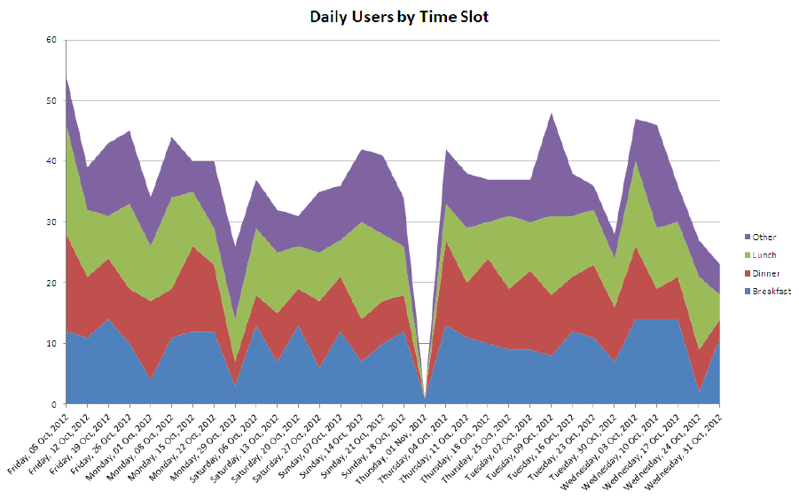
AirTight Management Console User Guide
248
Analytics
Analytics data is available with respect to the Wi-Fi clients that are visible to AirTight sensors, and the Wi-
Fi clients that associate with AirTight APs.
Visibility analytics presents information about clients in the vicinity of AirTight devices.
Association analytics presents information about the clients that connect to or associate with the AirTight
APs.
Content analytics captures information about the internet domains accessed by the clients associated
with the AirTight APs. This information is present in the association analytics file that can be downloaded
from Reports>Analytics.
You need administrator privileges to generate Analytics reports.
The analytics data can be used in various ways. For instance, if AirTight Management Console has been
deployed at a retail store, you can find the number of clients in and around the retail store by using
visibility analytics. Similarly, using association analytics, you can have an insight into the activity of the
authorized clients, the guest clients, and the SSIDs being used by these clients. Using association and
visibility analytics, you can establish network usage patterns, including but not limited to visitors to the
store, the number of visitors in the store at various times of the day.
A sample association analytics graph below shows the number of daily users per the time slot during
breakfast, lunch, dinner and other hours. These metrics are obtained using the association and visibility
analytics engine.
The analytics are currently provided in a raw comma separated value (.csv) file. The data in the .csv file
can be crunched and meaningful customer trends can be obtained using tools like Microsoft (MS) Excel.
This graph has been generated from the .csv file data using an MS Excel macro.
Daily Users by Time Slot derived from Analytics data
Reports
249
Sample macros would be available on request.
Analytics is a license-based feature. The Analytics tab in the Reports page would be enabled and
displayed, only after applying the Analytics license to the server. Contact support@airtightnetworks.com
for further details to procure the license for analytics and for the sample macros.
Download Analytics Data
Do the following to download visibility analytics data.
1. Select the Visibility Analytics option.
2. Enter the number of previous days for which you want to download this data.
3. Click Download.
The visibility analytics data is downloaded as a comma separated file (.CSV). Ensure that pop-ups are
enabled in your browser when you download the data.
The .csv file is typically saved to the 'Downloads' folder. It contains the following data
• Client MAC address
• Location of the client
• Best received signal strength indication (RSSI)
• MAC address of the sensor reporting best RSSI
• Client session duration
• Activity stop time (GMT)
• Activity stop time per the local time zone of the user-When the analytics data pertains to a location
floor, the local time zone set for its immediate parent location folder is considered. If the time zone for
the location folder has not been set, this field shows the activity stop time based on the server time
zone. Similarly, when the analytics data pertains to a location folder, the local time zone set for the
location folder is considered. If the time zone for the location folder has not been set, this field shows
the activity stop time based on the server time zone.
• Local Time Zone-When the analytics data pertains to a location floor, the local time zone set for its
immediate parent location folder is considered. If the time zone for the location folder has not been
set, this field shows the server time zone. Similarly, when the analytics data pertains to a location
folder, the local time zone set for the location folder is considered. If the time zone for the location
folder has not been set, this field shows the server time zone.
Note: The client may be visible to multiple sensors; the sensor reporting the best RSSI is recorded in the
.CSV file.
Do the following to download association analytics data.
1. Select the Association Analytics option.
2. Enter the from date and to date for which you want to download this data.
3. Click Download.
IMPORTANT: Edit the SSID profile associated with the AirTight APs to select the Association Analytics
check box. If this check box is not selected, the data related to AirTight APs associated with the
respective SSID will not appear in the .CSV file containing the Association Analytics data.
The association analytics data is downloaded as a comma separated file (.csv). Ensure that pop-ups are
enabled in your browser when you download the data.
The file is typically saved to the 'Downloads' folder.
The .csv file contains the following data
• Client MAC address
AirTight Management Console User Guide
250
• Protocol
• SSID
• Location
• Association start time (GMT) of the client
• Association end time (GMT)
• Association start time of the client per the local time zone of the user- When the analytics data
pertains to a location floor, the local time zone set for its immediate parent location folder is
considered. If the time zone for the location folder has not been set, this field shows the client
association start time the server time zone. Similarly, when the analytics data pertains to a location
folder, the local time zone set for the location folder is considered. If the time zone for the location
folder has not been set, this field shows client association start time based on the server time zone.
• Association end time of the client per the local time zone of the user- When the analytics data pertains
to a location floor, the local time zone set for its immediate parent location folder is considered. If the
time zone for the location folder has not been set, this field shows the client association end time
based on the server time zone. Similarly, when the analytics data pertains to a location folder, the
local time zone set for the location folder is considered. If the time zone for the location folder has not
been set, this field shows the client association end time based on the server time zone.
• Session duration
• Data transfer from client device in bytes
• Data transfer to client device in bytes
• Data rate in Kbps
• Smart device type
• Local Time Zone
• Location ID
• Domains Accessed
Top domains based on the data exchange are presented in the Domains accessed column of the CSV
file. The data in the Domains Accessed column is seen in the following format:<Domain name> (<data
transferred to the domain>/<data received from the domain>). Multiple domains are separated by a | sign.
Important: Internet domain related information is collected only if you select the Content Analytics
check box while configuring the SSID profile. Otherwise, the domains accessed column will be blank in
the CSV file.
The session duration could be less than the difference between the association end time and the
association start time, as it is calculated as the duration for which the client has actively accessed
network resources through the AirTight APs.
Back up Analytics data
You can backup Analytics data by executing the set db backup info or db backup command,
whenever you want to take a backup. Note that the size of the backed up database might be large if
Analytics data is backed up.
Manage Report Archive
The Archives tab allows you to view saved or archived reports generated by the AirTight Management
Console server. These reports are useful for trend analysis. An archived report is visible to a user who
has previously generated this report. A super user can see all archived reports.
Archived reports are not location specific. It depends on the privileges or rights of the user that has
logged in to AirTight Management Console. A superuser is able to see all archived reports. A poweruser
is able to see all archived reports for the customer account managed by him or her. An administrator,
operator and viewer are able to see self-archived reports only.
Reports
251
If you are logged in to the parent server of a server cluster, based on your role, you can see an
aggregated set of archived reports from the parent and child servers,
You can fetch, rename, and delete archived reports. You can also print a list of archived reports for a
location.
If an archived report has been generated on the parent server of a server cluster, it shows aggregated
data from the parent and child servers.
Fetch Archived Report
To fetch and view an archived report, do the following.
1. Go to Reports>Archives tab.
2. Select the location at which the report has been archived.
3. Select the check box for the report from the list of archived reports.
4. Click the fetch icon to fetch the report.
Rename Archived Report
To rename an archived report, do the following.
1. Go to Reports>Archives tab.
2. Select the location at which the report has been archived.
3. Select the check box for the report from the list of archived reports.
4. Click the rename icon and enter new name for the report.
Print Archived Report List for Location
To print a list of archived reports, do the following.
1. Go to Reports>Archives tab.
2. Select the location for which you want to print the list of archived reports.
3. Select the columns that you want in the printed list. Click any column name to select or deselect
columns.
4. Click the print icon. The print preview of the list of archived reports appears.
5. Click Print to print the list.
Delete Archived Report
To delete an archived report, do the following.
1. Go to Reports>Archives tab.
2. Select the location at which the report has been archived.
3. Select the check box for the report from the list of archived reports.
4. Click the delete icon. A message to confirm deletion appears.
5. Click Yes to confirm deletion of the archived report.
Schedule Report Generation
AirTight Management Console User Guide
252
You can schedule a report for one-time generation, or a recurring generation. You can schedule to e-mail
a report. While scheduling the report generation, you can also specify report archival details. Once the
report generation schedule has been defined, it is seen under Reports Scheduled by Me reports for the
user who has scheduled the report.
Important: Scheduled reports are e-mailed at incorrect times if incorrect time zone settings are
configured in the Server Initialization and Configuration Wizard from the Server Config shell. Choose the
correct time zone for proper delivery.
Note: When a server is a parent server in a server cluster and there are child servers mounted in the
parent server location tree, you will not be able to schedule reports on the child servers. Scheduling is
allowed only on reports local to the parent server. In general, scheduling reports on remote locations is
not allowed.
To schedule report generation, do the following.
1. Under Reports, select the appropriate report category.
2. Click the Add Schedule hyperlink following the report you want to schedule.
3. Add Schedule is displayed as seen in the images shown below.
4. Select the Report Format. The available options are pdf, html and xml.
If you want to schedule the report for one time generation, specify the details under the One Time
Generation tab.
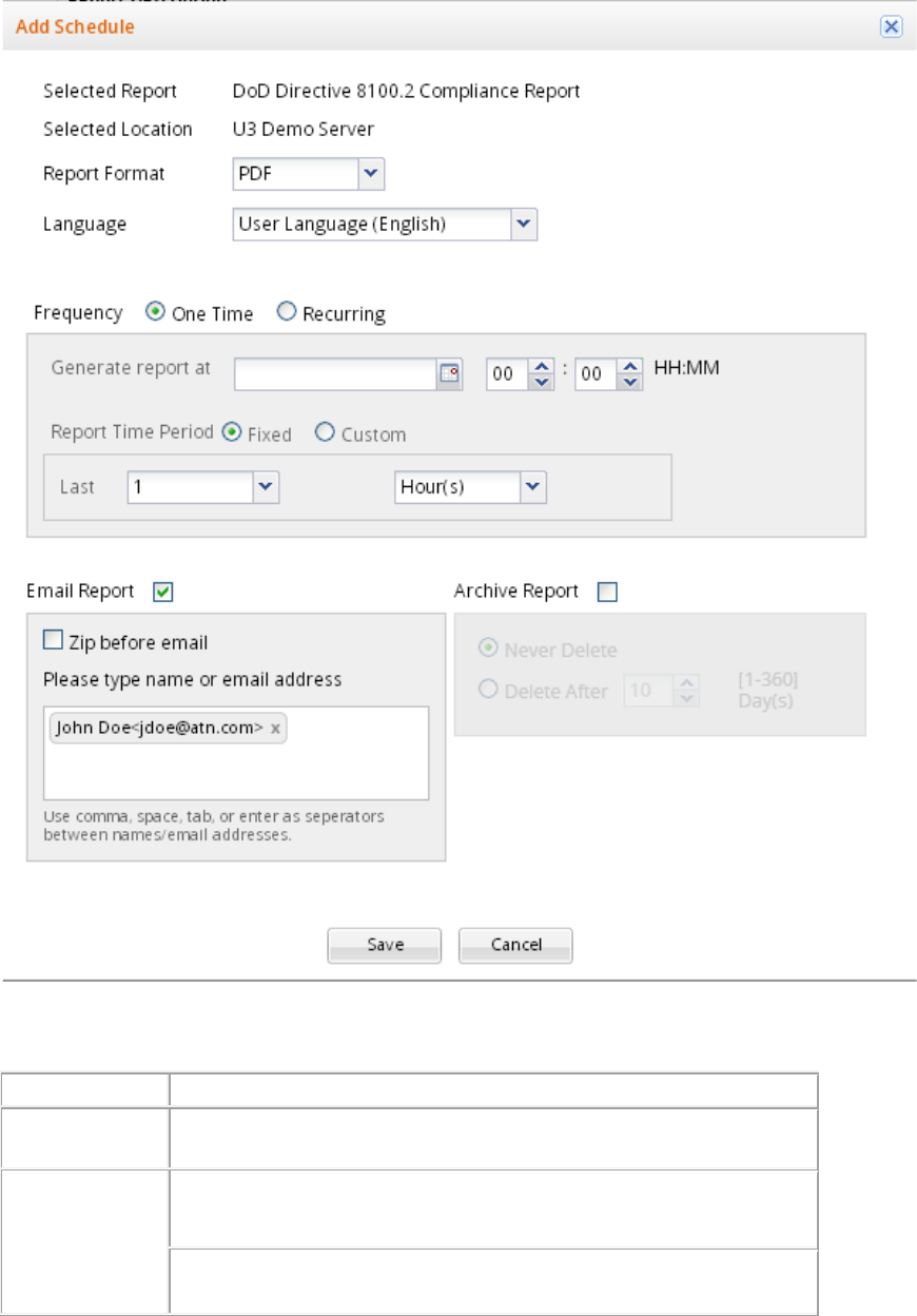
Reports
253
Add Schedule - One time Generation
The following table describes the fields present on the One Time Generation tab.
Field
Description
Generate
Report
at
Click the calendar icon to specify the date of report generation. Also specify
the time of the report generation.
Report Time
Period
Select the Last option to specify the time period preceding the report
delivery date and time. Specify the number of preceding hours, days or
months for which you want to generate the report.
Select the Customize option to specify a date-wise duration for which you
want the report. Specify the From date and time and To date and time.
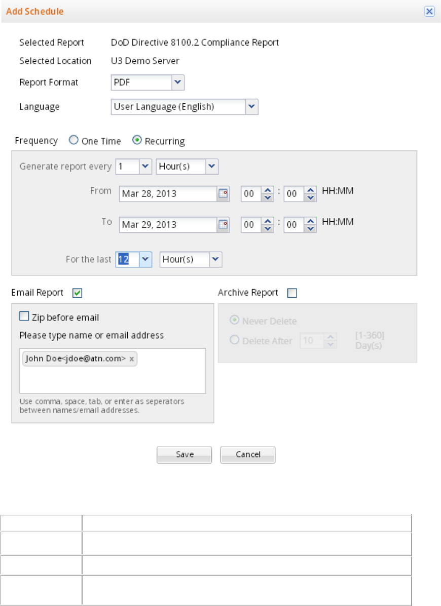
AirTight Management Console User Guide
254
If you want to schedule the report for recurring generation, specify the details under the Recurring
Generation tab.
Add Schedule - Recurring Generation
The following table describes the fields present on the Recurring Generation tab.
Field
Description
Generate Report
every
Specify the frequency in number of hours, days, or months for report generation.
Start Date
Select the start date and time for which you want to generate the report.
End Date
Select the end date and time for which you want
to generate the report.

Reports
255
Report Time
Period
Select the time period in number of hours, days, or months for which the report is
to be generated.
Send report by e-mail
If you want to email the report on generation, select the Email Report check box. If you want to zip the
report before sending it in an email, select the Zip before email check box.
If your email id is mentioned in the schedule, you will be able to see the report under Reports Scheduled
for Me section in the Schedules tab. If you have added the schedule, you will be able to see the report
under the Reports Scheduled by Me section in the Schedules tab.
Archive report
To archive a report, select the Archive Report check box. If you want to permanently retain the archived
report, select the Never Delete option. To retain the archived report for a fixed duration, select the Delete
After option and specify the duration in days, after which the archived report is to be deleted from the
system. The minimum and maximum durations to retain the archived report is 1 day and 360 days
respectively.
View Report Schedules
You can view the report schedules defined by you and for you under the Report Schedules tab.
If your email id is mentioned in the schedule, you will be able to see the report under Schedules For Me
section in the Report Schedules tab. If you have added the schedule, you will be able to see the report
under the Schedules by Me section in the Report Schedules tab.
Click Schedules By Me to view a list of report schedules defined by you.
In the Schedules By Me section, you will see the report name, schedule information, next report delivery
date and time, the location for which the report is being generated and the duration for which the report
has been generated in this section.
Click Schedules For Me to view a list of reports scheduled for you.
In the Schedules For Me section, you will see the report name, schedule information, next report delivery
date and time, the location for which the report is being generated and the duration for which the report
has been generated, and the name of the user who has defined the report schedule.
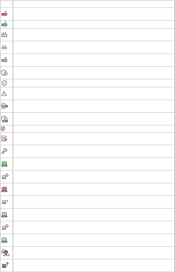
257
Glossary of Icons
Following is a list of the device related icons seen on AirTight Management Console.
Icon
Description
Rogue AP-Active: This icon shows that a Rogue AP is active and visible
to Sensor(s).
Authorized AP: This icon shows that the AP is an authorized AP
Authorized AP-Active: This icon shows that an authorized AP is active
and visible to Sensor(s).
Authorized AP-Inactive: This icon shows that an Authorized AP that was
earlier visible to Sensor(s) is inactive.
External AP-Active: This icon shows that an External AP is active and
visible to Sensor(s).
Quarantine Pending: This icon shows that the AP/Client needs to be
quarantined, but quarantine is pending.
Quarantined: This icon shows that the AP/Client has been quarantined.
Quarantine Error: This icon shows that some error has occurred while
quarantining a device.
DoS Quarantine: This icon shows that the quarantine against DoS attack
on this device is in progress.
DoS Quarantine Pending: This icon shows that the quarantine against
DoS attack on this device is pending.
Banned Device: This icon shows that the AP/Client is a banned device.
Remove from to Banned List: This icon shows that the AP/Client has been
removed from the Banned List.
Troubleshooting: This icon shows that troubleshooting is in progress on a
device.
Authorized Client-Active: This icon shows that an Authorized Client is
active and visible to Sensor(s).
Authorized Client-Inactive: This icon shows that an Authorized Client that
was earlier visible to Sensor(s) is inactive.
Rogue Client-Active: This icon shows that a Rogue Client is active and
visible to Sensor(s).
Rogue Client-Inactive: This icon shows that a Rogue Client that was
earlier visible to Sensor(s) is inactive.
External Client-Active: This icon shows that an External Client is active
and visible to Sensor(s).
External Client-Inactive: This icon shows that an External Client that was
earlier visible to Sensor(s) is inactive.
Guest Client-Active: This icon shows that a Guest Client is active and
visible to Sensor(s).
Guest Client-Inactive: This icon shows that a Guest Client that was earlier
visible to Sensor(s) is inactive.
Uncategorized Client-Active: This icon shows that an Uncategorized
Client is active and visible to Sensor(s).
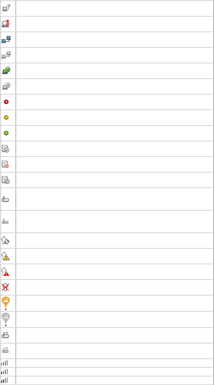
AirTight Management Console User Guide
258
Uncategorized Client-Inactive: This icon shows that an Uncategorized
Client that was earlier visible to Sensor(s) is inactive.
DoS Attacker: This icon shows the device from which the DoS attack is
being launched.
Client in Adhoc Mode-Active: This icon shows that a Client in adhoc mode
is active and visible to Sensor(s).
Client in Adhoc Mode-Inactive: This icon shows that a Client that was
earlier in adhoc mode and visible to Sensor(s) is inactive.
AirTight Mobile Installed-Active: This icon shows that AirTight Mobile is
installed and active on the Client.
AirTight Mobile Installed-Inactive: This icon shows that AirTight Mobile is
installed but is inactive on the Client.
AirTight Mobile Risk Level-High: This icon shows that AirTight Mobile is
installed on the Client and the risk level on that Client is high.
AirTight Mobile Risk Level-Medium: This icon shows that AirTight Mobile
is installed on the Client and the risk level on that Client is medium.
AirTight Mobile Risk Level-Low: This icon shows that AirTight Mobile is
installed on the Client and the risk level on that Client is low.
AirTight Mobile Report Available: This icon indicates that a AirTight Mobile
report generated earlier is available for the selected Client.
AirTight Mobile Report Not Available: This icon indicates that a AirTight
Mobile report is never generated for the selected Client.
AirTight Mobile Report Scheduled: This icon indicates that a SAFE report
will be generated for the selected Client when it become active.
Sensor-Active: This icon shows that the Sensor is connected to the
Server and is actively monitoring the network. This Sensor has the latest
software version and does not need to be upgraded.
Sensor-Inactive: This icon shows that the Sensor is not connected to the
Server and is currently not monitoring the network. This Sensor has the
latest software version and does not need to be upgraded
Sensor Upgrade In Progress: This icon shows that Sensor Upgrade is in
progress.
Sensor Upgrade Required: This icon shows that the Sensor needs to be
upgraded to a new version.
Sensor Upgrade Failed: This icon shows that the Sensor upgrade to a
new version has failed.
Sensor Indeterminate: This icon shows that the Sensor is in an
indeterminate or irrecoverable state.
Network Detector-Active: This icon shows that the ND is connected to the
Server and is currently contributing into wired detection of APs.
Network Detector-Inactive: This icon shows that the ND is not connected
to the Server and is currently not contributing into wired detection of APs.
AP/Sensor Combo-Active: This icon indicates that the AP/Sensor combo
device is connected to the Server and is monitoring the network.
AP/Sensor Combo-Inactive: This icon indicates that the AP/Sensor combo
device is connected to the Server and is inactive.
RSSI Level 0: This icon shows very low signal available.
RSSI Level 1: This icon shows low signal strength.
RSSI Level 2: This icon shows medium signal strength.
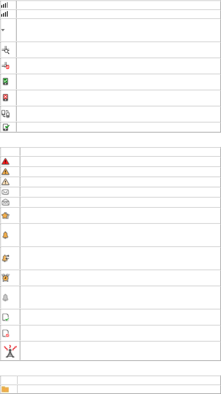
glossary_of_icons
259
RSSI level 3: This icon shows strong signal strength
RSSI Level 4: This icon shows very strong signal strength.
Display Columns: Most fields in the table can be selected for display or
optionally hidden. This button allows selection and configuration of
parameters to show and hide in the table.
Monitored Network: This icon indicates that the network is being
monitored by a sensor.
Unmonitored Network: This icon indicates that the network is not being
monitored by a sensor.
Approved Smart Device: This icon indicates that the authorized client is
an approved smart device.
Unapproved Smart Device: This icon indicates that the authorized client is
an unapproved smart device.
Change Device Type: This icon indicates a change in the smart device
type.
Smart Device: This icon indicates that the guest client is a smart device.
Following is a list of the event related icons seen on AirTight Management Console.
Icon
Description
High: This icon indicates an event with high severity.
Medium: This icon indicates an event with medium severity.
Low: This icon indicates an event with low severity.
New: This icon indicates an event that is neither read nor acknowledged.
Read: This icon indicates that the event has been read.
Acknowledged: This icon indicates that the event has been read and
acknowledged.
Live: This icon indicates a live event in which the triggers that raised the
event are operational or continue to exist; this event has a valid start
time stamp.
Live and Updated: This icon indicates a live event that has been
updated, that is, some activity has occurred since the event was last
read.
Instantaneous: This icon indicates an instantaneous event that are
triggered based on a trigger that do not have continuity.
Expired: This icon indicates an expired event in which the triggers that
raised the event are not operational or have ceased to exist; this event
has a valid start and stop time stamp.
Secure: This icon indicates an event that does not contribute to the
vulnerability status of the system.
Vulnerable: This icon indicates an event that contributes to the
vulnerability status of the system.
Interference device/jammer icon: This icon shows the device which is RF
Jammer or source of non-Wi Fi interference.
Following is a list of the location related icons seen on AirTight Management Console.
Icon
Description
This icon indicates a location folder.
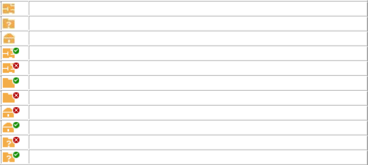
AirTight Management Console User Guide
260
This icon indicates a location floor.
This icon indicates an unknown location floor.
This icon indicates root location.
This icon indicates a secure location floor.
This icon indicates a vulnerable location floor.
This icon indicates a secure location folder.
This icon indicates a vulnerable location folder.
This icon indicates a vulnerable root location.
This icon indicates a secure root location.
This icon indicates a vulnerable unknown location floor.
This icon indicates a secure unknown location floor.