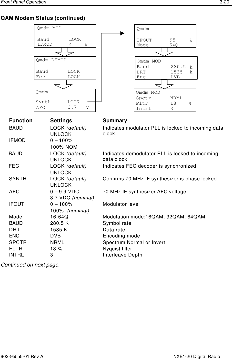
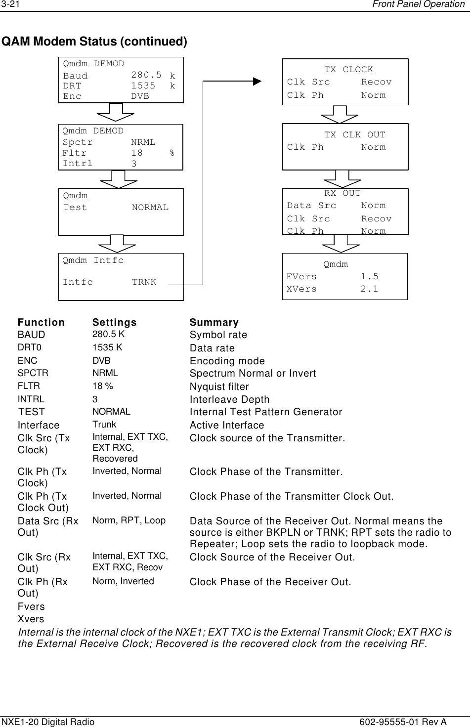
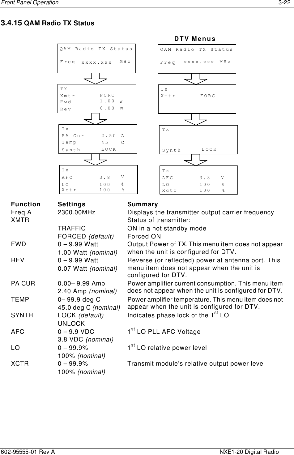
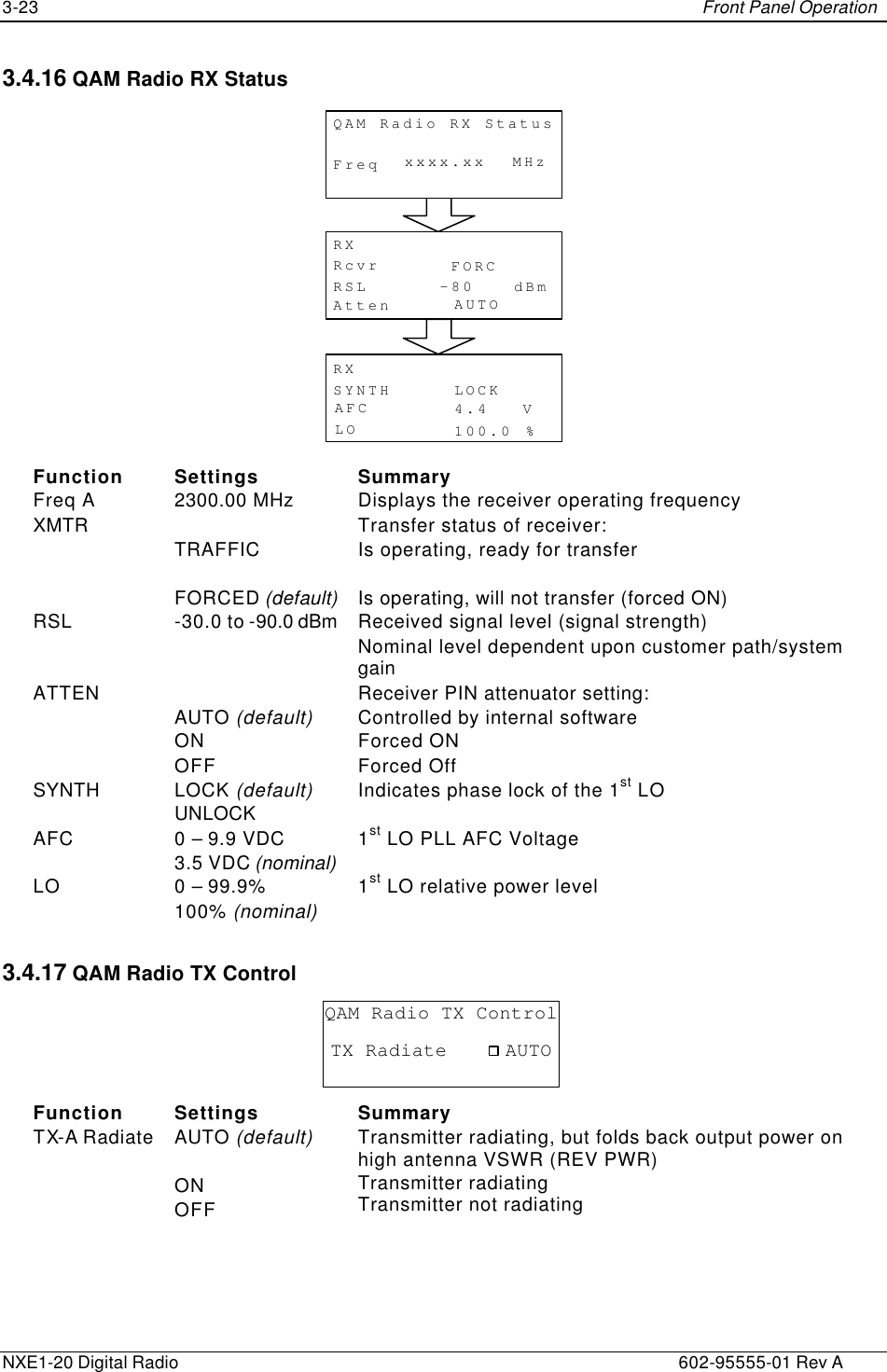
Moseley Associates NXE1-20 NXE1-20 User Manual 602 95555 01
Moseley Associates Inc NXE1-20 602 95555 01
UserManual.wiki
>
Moseley Associates
>
NXE1 20 User Manual
users manual
Navigation menu
Upload a User Manual
Namespaces
Wiki Guide
HTML
PDF
Info
Views
User Manual
Discussion / Help
Navigation

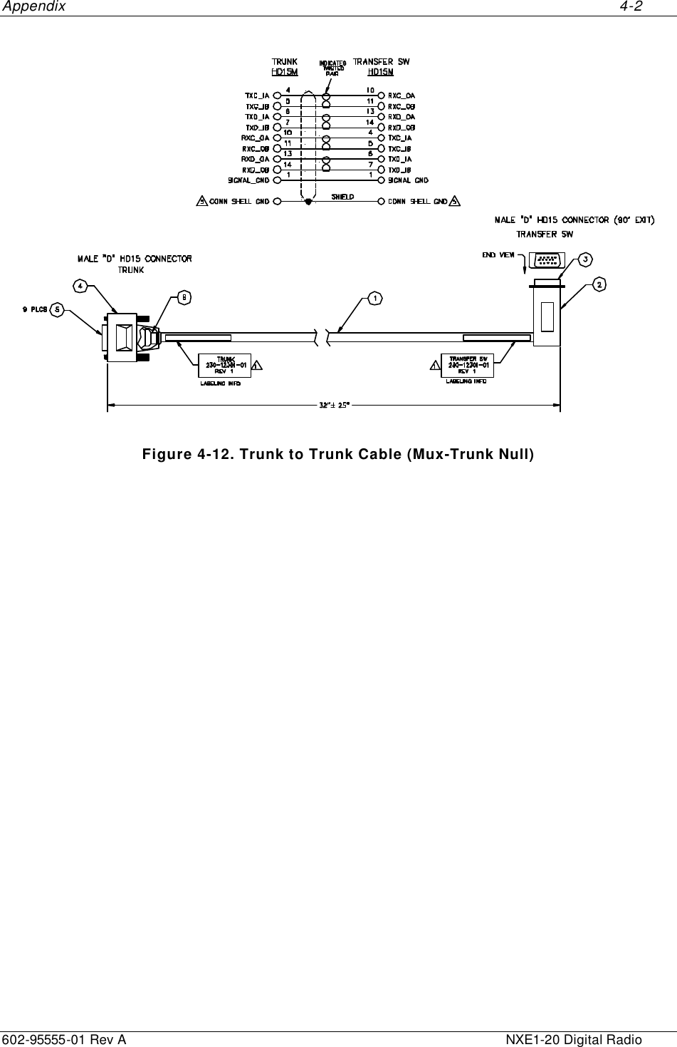
![Appendix 5-4 602-95555-01 Rev A NXE1-20 Digital Radio The most serious of the secondary effect is reflection from surfaces in or near the path, such as the ground or structures. For shallow angle microwave reflections, there will be a 180° (half wavelength) phase shift at the reflection point. Additionally, reflected energy travels farther and arrives later, directly increasing the phase delay. The difference in distance traveled by the direct waves and the reflected waves, expressed in wavelengths of the carrier frequency, is added to the half wavelength delay caused by reflection. Upon arrival at the receiving antenna, the reflected signal is likely to be out of phase with the direct signal, and may tend to add to or cancel the direct signal. The extent of direct signal cancellation (or augmentation) by a reflected signal depends on the relative powers of the direct and the reflected signals, and on the phase angle between them. Maximum augmentation will occur when the signals are exactly in phase. This will be the case when the total phase delay is equal to one wavelength (or equal to any integer multiple of the carrier wavelength); this will also be the case when the distance traveled by the reflected signal is longer than the direct path by an odd number multiple of one-half wavelength. Maximum cancellation will occur when the signals are exactly out of phase, or when the phase delay is an odd multiple of one-half wavelength, which will occur when the reflected waves travel an integer multiple of the carrier wavelength farther than the direct waves. Note that the first cancellation maximum on a shallow angle reflective path will occur when the phase delay is one and one-half wavelengths, caused by a path one wavelength longer than the direct path. The direct radio path, in the simplest case, follows a geometrically straight line from transmitting antenna to receiving antenna. However, geometry shows that there exist an infinite number of points from which a reflected ray reaching the receiving antenna will be out of phase with the direct rays by exactly one wavelength. In ideal conditions, these points form an ellipsoid of revolution, with the transmitting and receiving antennas at the foci. This ellipsoid is defined as the first Fresnel zone. Any waves reflected from a surface that coincides with a point on the first Fresnel zone, and received by the receiving antenna, will be exactly in phase with the direct rays. This zone should not be violated by intruding obstructions, except by specific design amounts. The first Fresnel zone, or more accurately the first Fresnel zone radius, is defined as the perpendicular distance from the direct ray line to the ellipsoidal surface at a given point along the microwave path. It is calculated as follows: F1 = 2280 × [(d1×d2) / (f × (d1+d2))]½ feet Where, d1 and d2 = distances in statute miles from a given point on a microwave path to the ends of the path (or path segment). f = frequency in MHz. F1 = first Fresnel zone radius in feet. There are in addition, of course, the second, third, fourth, etc. Fresnel zones, and these may be easily computed, at the same point along the microwave path, by multiplying the first Fresnel zone radius by the square root of the desired Fresnel zone number. All odd numbered Fresnel zones are additive, and all even numbered Fresnel zones are canceling.](https://usermanual.wiki/Moseley-Associates/NXE1-20/User-Guide-224356-Page-68.png)
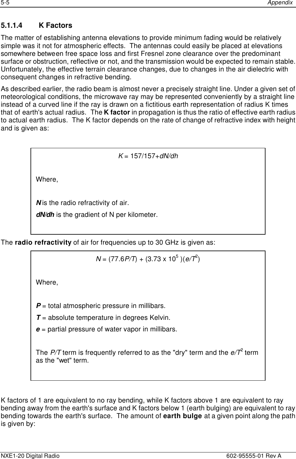
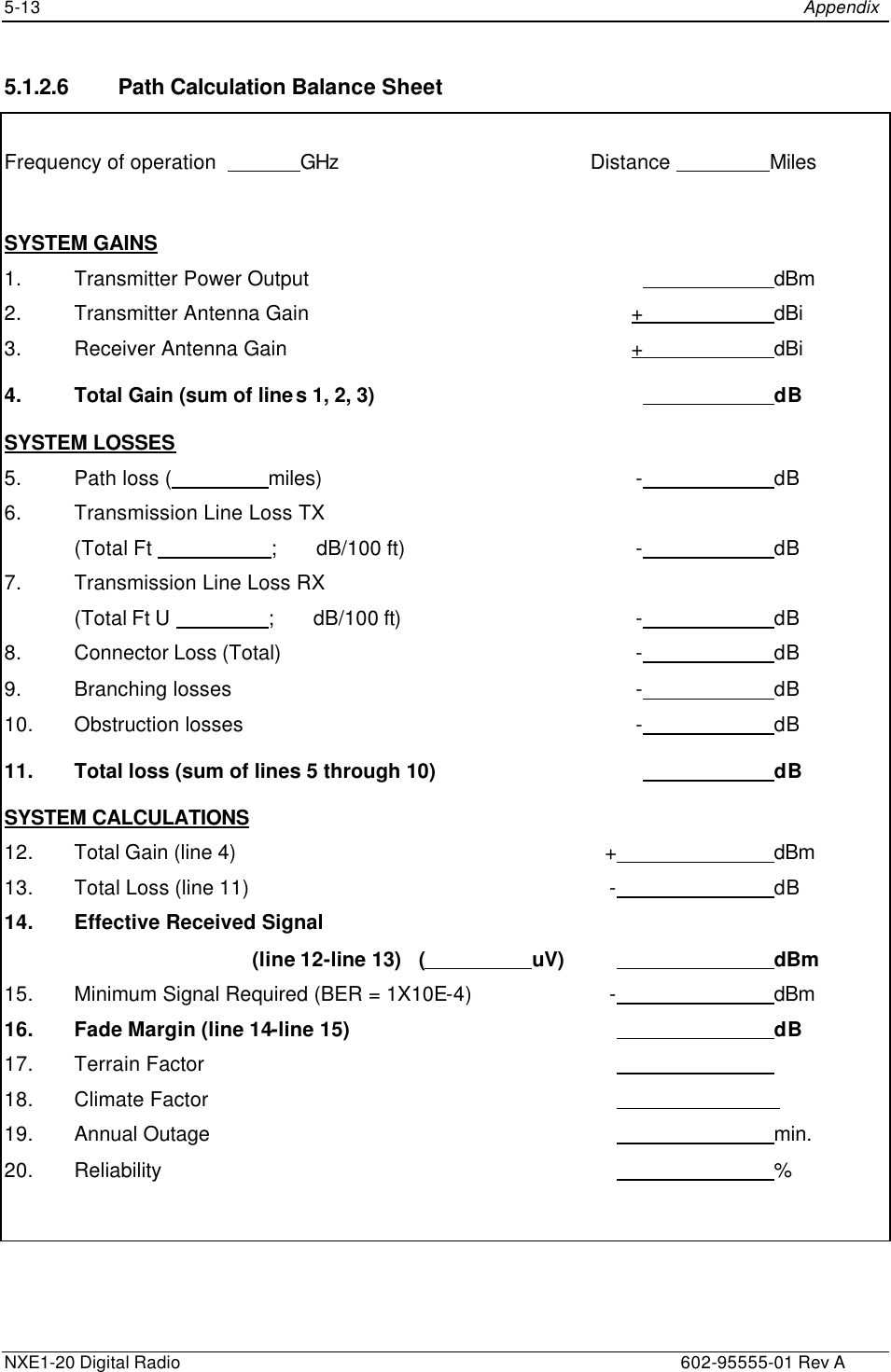
![Appendix 5-8 602-95555-01 Rev A NXE1-20 Digital Radio The following instructions will aid you in completing the Path Calculation Balance Sheet (see Section 5.2.7): Instructions A. Line 1. Enter the power output of the transmitter in dBm. Examples: 5w = +37.0 dBm, 6.5w = +38.0 dBm, 7w = +38.5 dBm, 8w = +39.0 dBm (dBm = 30 + 10 Log Po [in watts]). B. Lines 2 & 3. Enter Transmitter and Receiver antenna gains over an isotropic source. Refer to the Antenna Gain table below for the power gain of the antenna. Note: If the manufacturer quotes a gain in dBd (referred to a dipole), dBi is approximately dBd +1.1 dB. C. Line 4. Total lines 1, 2, and 3, and enter here. This is the total gain in the proposed system. D. Line 5. Enter amount of free space path loss as determined by the formula given in Section 5.2.2. E. Line 6. Enter the total transmitter transmission line loss. Typical losses can be found in Table 5-3. Table 5-3 Transmission Line Loss FREQUENCY BAND LDF4-50 (per 100 meters) LDF5-50 (per 100 meters) 450 MHz 3.46 dB 2.65 dB 1000 MHz 5.38 dB 4.12 dB 2000 MHz 8.02 dB 6.11 dB 6000 MHz 15.6 dB - F. Line 7. Enter the total receiver transmission line loss (see Table 5-3 above). G. Line 8. Enter the total connector losses. A nominal figure of -0.5 dB is reasonable (based on 0.125 dB/mated pair). H. Line 9. Enter all other miscellaneous losses here. Such losses might include power dividers, duplexers, diplexers, isolators, isocouplers, and the like. Losses are up to 1.5 dB per terminal. These only apply for full duplex systems. These depend on the type of filter used. If the bandpass filters are used, the Tx and Rx losses are 0.75 dB. If the Notch filters are used, the losses are 1.5 dB. For even coupler MHSB applications, add 3 dB power divider losses. I. Line 10. Enter obstruction losses due to knife-edge obstructions, etc. J. Line 11. Total lines 5 to 10 and enter here. This is the total loss in the proposed system. K. Line 12. Enter the total gain from line 4. L. Line 13. Enter the total loss from line 11.](https://usermanual.wiki/Moseley-Associates/NXE1-20/User-Guide-224356-Page-72.png)