Moseley Associates NXE1-20 NXE1-20 User Manual 602 95555 01
Moseley Associates Inc NXE1-20 602 95555 01
users manual
User Manual
NXE1-20
Digital Radio
Doc. 602-95555-01
January 10, 2002

Table of Contents ii
602-95555-01 Rev A NXE1-20 Digital Radio
NXE1 Manual Dwg # 602-95555-01; Revision Levels:
Section Drawing No: REV Revised /
Released Reason
NXE1-20 602-95555-01 A SN NEW

iii Table of Contents
602-95555-01 Rev A NXE1-20 Digital Radio
Table of Contents
1 SYSTEM DESCRIPTION............................................................................1-1
1.1 INTRODUCTION ..........................................................................................................1-1
1.2 SYSTEM FEATURES .....................................................................................................1-1
1.3 TYPICAL CONFIGURATIONS..........................................................................................1-3
1.3.1 Data Rate and Interface....................................................................................1-3
1.3.2 Standalone Operation.......................................................................................1-3
1.3.3 Hot Standby (Protected) Operation....................................................................1-3
1.4 REGULATORY NOTICES ...............................................................................................1-5
1.5 SYSTEM DESCRIPTION (QAM)......................................................................................1-5
1.5.1 Introduction....................................................................................................1-5
1.5.2 QAM Modulator/IF Upconverter .......................................................................1-7
1.5.3 RF Upconverter...............................................................................................1-8
1.5.4 Power Amplifier (PA).......................................................................................1-9
1.5.5 RF Downconverter...........................................................................................1-9
1.5.6 QAM Demodulator/IF Downconverter..............................................................1-10
2 INSTALLATION ..............................................................................................................................................2-1
2.1 UNPACKING...............................................................................................................2-1
2.2 NOTICES....................................................................................................................2-1
2.3 RACK MOUNT ............................................................................................................2-2
2.4 DUPLEXER: INTERNAL/EXTERNAL ................................................................................2-2
2.5 REAR PANEL CONNECTIONS & INDICATORS...................................................................2-2
2.6 POWER REQUIREMENTS...............................................................................................2-4
2.6.1 Power Supply Card Slot Details.........................................................................2-4
2.6.2 AC Line Voltage..............................................................................................2-5
2.6.3 DC Input Option..............................................................................................2-5
2.6.4 Fusing............................................................................................................2-5
2.7 POWER-UP SETTING....................................................................................................2-6
2.8 DATA INTERFACE .......................................................................................................2-7
2.8.1 4xE1/T1 MUX Channel Configurations ..............................................................2-7
2.9 HOT STANDBY (PROTECTED) CONFIGURATION...............................................................2-8
2.9.1 Hot/Cold Standby Modes..................................................................................2-9
2.9.2 Hot Standby Control using the Moseley TP64....................................................2-10
2.9.3 Hot Standby Control with Single Unit...............................................................2-13
2.10 SITE INSTALLATION ..................................................................................................2-14
2.11 ANTENNA/FEED SYSTEM ...........................................................................................2-14
2.11.1 Antenna Installation.......................................................................................2-14
3 FRONT PANEL OPERATION.....................................................................................................................3-1
3.1 INTRODUCTION ..........................................................................................................3-1
3.2 FRONT PANEL OPERATION...........................................................................................3-1
3.2.1 LCD Display...................................................................................................3-1
3.2.2 Cursor and Screen Control Buttons....................................................................3-2
3.2.3 LED Status Indicators ......................................................................................3-3
3.2.4 Screen Menu Tree Structure ..............................................................................3-3
3.3 MAIN MENU ..............................................................................................................3-4
3.3.1 Launch Screens ...............................................................................................3-4
3.4 SCREEN MENU SUMMARIES .......................................................................................3-10

Table of Contents iv
602-95555-01 Rev A NXE1-20 Digital Radio
3.4.1 Meter ...........................................................................................................3-10
3.4.2 System: Card View.........................................................................................3-10
3.4.3 System: Power Supply ....................................................................................3-11
3.4.4 System: Info..................................................................................................3-11
3.4.5 System: Basic Card Setup ...............................................................................3-12
3.4.6 System: Factory Calibration............................................................................3-13
3.4.7 System: Unit-Wide Parameters ........................................................................3-14
3.4.8 System: Date/Time.........................................................................................3-15
3.4.9 System: Transfer............................................................................................3-15
3.4.10 External I/O..................................................................................................3-16
3.4.11 Alarms..........................................................................................................3-17
3.4.12 Faults...........................................................................................................3-18
3.4.13 G821 Parameters...........................................................................................3-18
3.4.14 QAM Modem Status.......................................................................................3-19
3.4.15 QAM Radio TX Status ....................................................................................3-22
3.4.16 QAM Radio RX Status....................................................................................3-23
3.4.17 QAM Radio TX Control..................................................................................3-23
3.4.18 QAM Radio RX Control..................................................................................3-24
3.4.19 QAM Modem Configure..................................................................................3-25
3.4.20 QAM Radio TX Configure...............................................................................3-31
3.4.21 QAM Radio RX Configure...............................................................................3-32
3.5 NMS/CPU PC CONFIGURATION SOFTWARE.................................................................3-32
3.6 UP/DOWN CONVERTER: FREQUENCY ADJUST ...............................................................3-32
3.6.1 TX Frequency Adjust......................................................................................3-32
3.6.2 AFC Level—RX.............................................................................................3-33
4 DATA INTERFACE CABLES.......................4-1
5 APPENDIX....................................................................................5-3
5.1 PATH EVALUATION INFORMATION ................................................................................5-3
5.1.1 Introduction....................................................................................................5-3
5.1.2 Path Analysis..................................................................................................5-7
5.2 ABBREVIATIONS & ACRONYMS..................................................................................5-14
5.3 CONVERSION CHART .................................................................................................5-16
NXE1 Digital Radio 602-13068-01 Rev A
1 System Description
1.1 Introduction
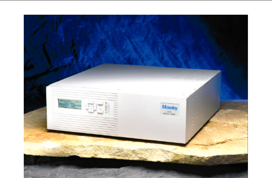
The NXE1-20 is a spectrum-scalable point-to-point digital radio that can deliver 8Mbps of data.
Advanced modulation and digital processing techniques allow one radio to deliver user-defined
rates from 512 kbps to 8Mbps
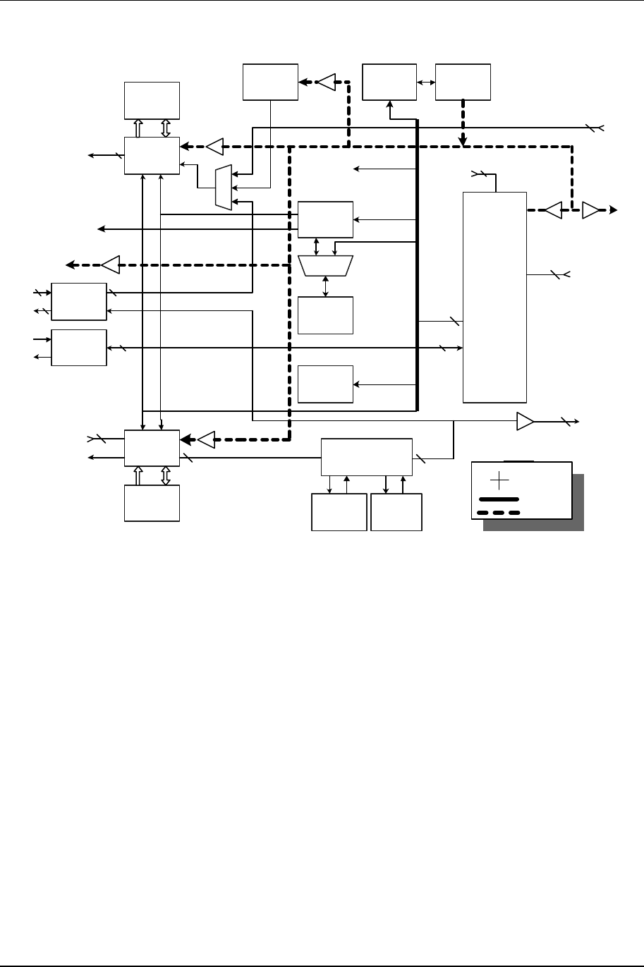
The product is an all-digital, open-architecture, modular system (see Figure 1-1 below). The
versatility and power of the product comes from a complete range of “plug and play” personality
modules.
Figure 1-1. NXE1-20 Modular Open Architecture
The high spectral efficiency of the NXE1-20 is achieved by user-selectable QPSK, or 16 QAM.
Powerful Reed-Solomon error correction, coupled with a 20-tap adaptive equalizer, provides
unsurpassed signal robustness in hostile RF environments. .
.
1.2 System Features
§ Selectable Rates: 512 kbps to 8.448 Mbps
§ Selectable Spectral Efficiency of 1.6 or 3.2 bps/Hz
§ QPSK & 16 QAM Modulation
§ Powerful Reed-Solomon Error Correction with up to 12 level interleaver
§ Built-in Adaptive Equalizer
§ Internal Duplexer or external for hot standby system
§ Independent Synthesized Tx & Rx units
§ Auto / Manual Power Control of up to 20 dB
§ Built-in Auto Pin Diode Attenuator for powerful signals
§ Accurate Digital Filtering for adjacent channel rejection
§ 386 Processor-based controller
§ Extensive LCD screen status monitoring

System Specifications & Description 1-2
602-95555-01 Rev A NXE1-20 Digital Radio
§ Built-in BER Meter
§ Built-in NMS
§ Monitoring & Time Stamping
§ Monitor up to 4 external Analog & Digital I/O
§ Readout of RSL in dBm
§ Completely modular

1-3 System Specifications & Description
NXE1-20 Digital Radio 602-95555-01 Rev A
1.3 Typical Configurations
1.3.1 Data Rate and Interface
Table 1-1 provides basic data channel capabilities for the NXE1-20. See Section 2 (Installation)
for more detailed information.
Table 1-1.NXE1-20 Data Channel Configurations
Data Rate MUX Hardware Channels Interface(s)
1.5 Mbps-8 Mbps 2 or 4 x E1/T1 2 or 4 G.703, E1/T1
512 kbps-2 Mbps QAM Modem 1 Fractional E1/T1
512 kbps-2 Mbps QAM Modem 1 V35, RS449
1.3.2 Standalone Operation
The NXE1-20 may be used as a standalone digital radio with an interface in the modem or with a
Multiplexer with 2 or 4 E1/T1 interfaces. The Multiplexer has an overhead channel which can be
utilized by the customer
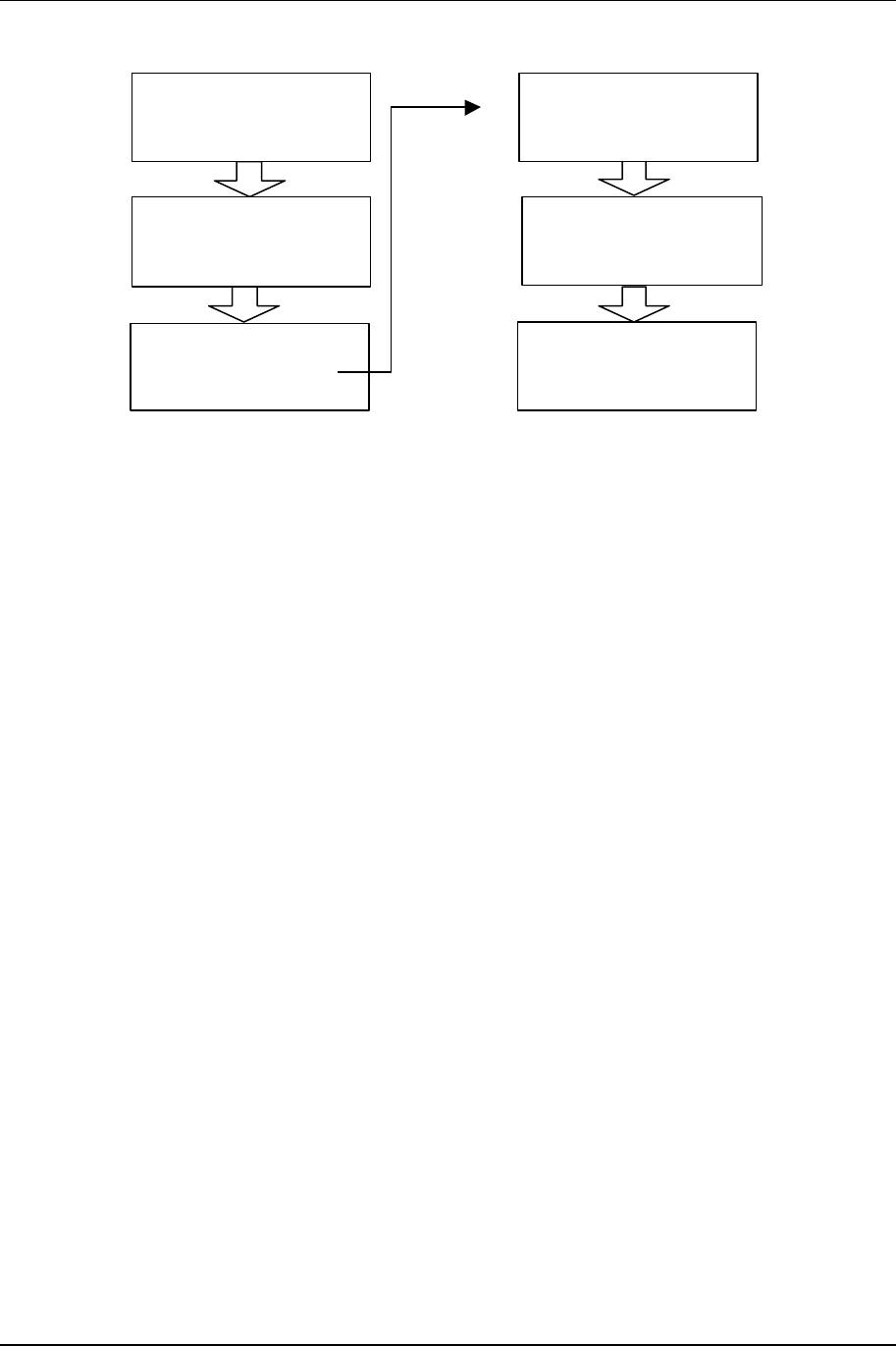
1.3.3 Hot Standby (Protected) Operation
The product in a hot standby configuration as depicted in Fig.1-3, using two NXE1-20 radios and
a TP64 transfer panel.
System Specifications & Description 1-4
602-95555-01 Rev A NXE1-20 Digital Radio
TX RF
RELAY
DUPLEXER
DATA
SWITCH/
TRANSFER
LOGIC
TP64 TRANSFER
PANEL
NXE1 RADIO A
NXE1 RADIO B
DATA
TX
TX
RX RF
SPLITTER
RX
RX
ANTENNA
DATA
DATA
CNTL
CNTL
Figure 1-3. NXE1-20 Hot Standby – Two Discrete Radios with Transfer Panel
1-5 System Specifications & Description
NXE1-20 Digital Radio 602-95555-01 Rev A
1.4 Regulatory Notices
FCC Part 15 Notice
This equipment has been tested and found to comply with the limits for a Class A digital device,
pursuant to part 15 of the FCC Rules. These limits are designed to provide reasonable protection
against harmful interference when the equipment is operated in a commercial environment. This
equipment generates, uses, and can radiate radio frequency energy and, if not installed and used
in accordance with the instruction manual, may cause harmful interference to radio
communications. Operation of this equipment in a residential area is likely to cause harmful
interference, in which case the user will be required to correct the interference at his expense.
Any external data or audio connection to this equipment must use shielded cables.
EC Declaration of Conformity
1.5 System Description (QAM)
1.5.1 Introduction
The product is a full-duplex digital radio. The following sections describe the TX system, RX
system, followed by sub-system components. Please reference the accompanying block
diagrams for clarification.
We will follow the typical end-to-end progression of a radio system starting with the TX baseband
inputs, to the QAM modulator, followed by the upconversion process and the power amplifier.
We then proceed to the RX preamplifier input, the downconversion process, followed by the QAM
demodulator and baseband outputs.
RF Linear
PA
Back
Plane
Antenna
12.8 MHz
Data, Address, I 2C, SPI Bus
Duplexer
Front Panel
Ribbon Cable
Universal
Input AC
(DC Optional)
System
Monitor
(A/D)
RF Module
Down Converter
Up Converter
IF Card
Down Converter
Up Converter
400 MHz-
1.5 GHzTX
RX
70 MHz
QAM Modem
Demodulator
Modulator
Intelligent
MUX
+5/+15 VDC
130 Watt
Power
Supply
BarGraph
4 x 20 LCD Display
Status LEDs
Front
Panel
System CPU
NMS
Remote I/O
Front Panel Interface
Serial PC Interface
Status/Command/Control I/O
4 Port
Data/Voice
Interface
Channel 1
Channel 2
Channel 3
Channel 4
Trunk
Transfer Panel I/O
QAM Modem Module
+15 VDC
PA Control/
Current
Sense

System Specifications & Description 1-6
602-95555-01 Rev A NXE1-20 Digital Radio
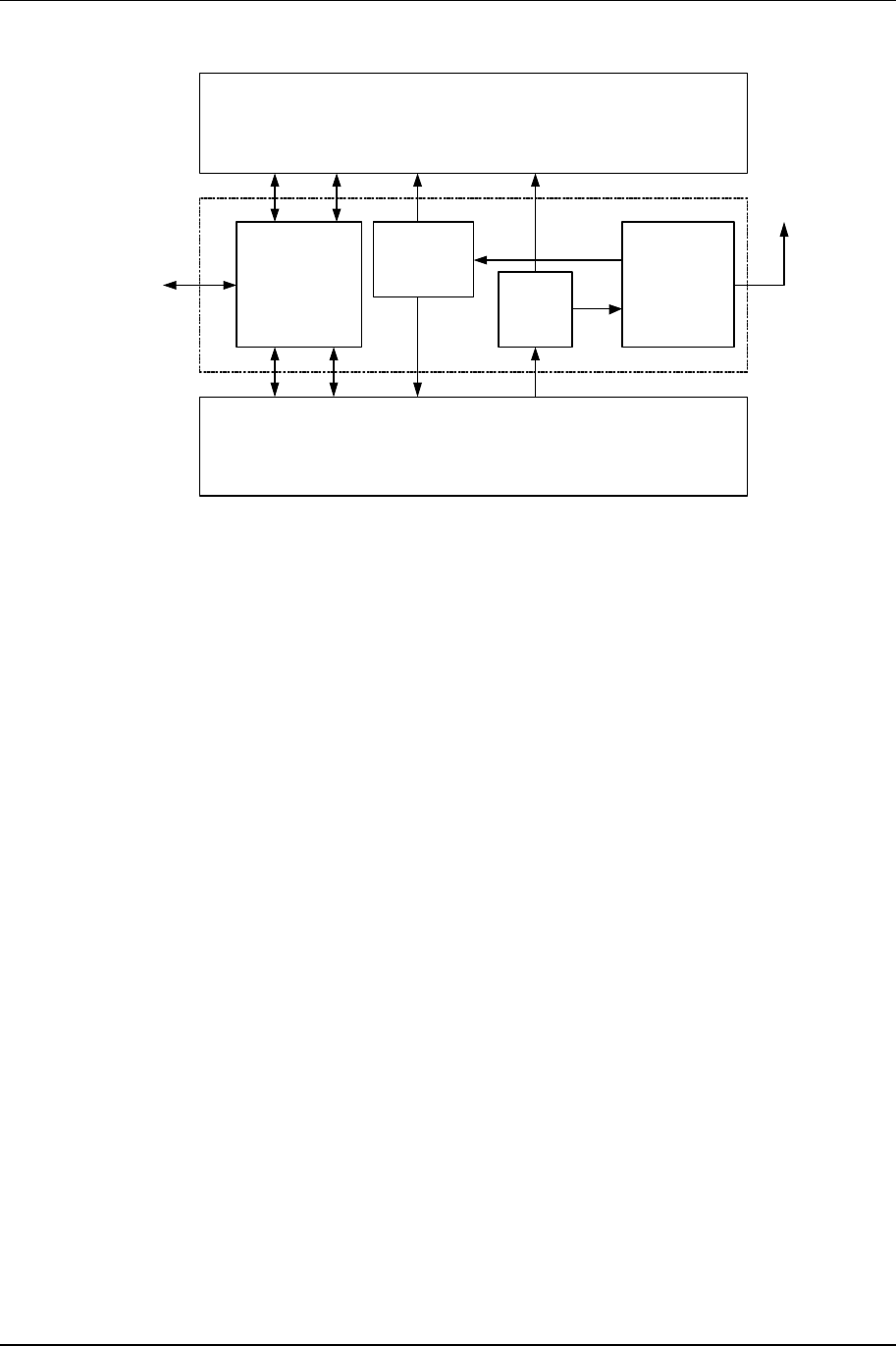
Figure 1-12. NXE1-20 System Block Diagram
.
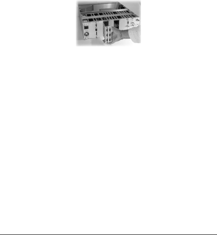
All modules (excluding the Front Panel and Power Amplifier) are interconnected via the
backplane that traverses the entire width of the unit. The backplane contains the various
communication buses as well as the PA (Power Amplifier) control and redundant transfer
circuitry. See Figure 1-13 below for locations of the Backplane and the Power Amplifier. The
power supply levels and status are monitored on the backplane and the NMS/CPU card
processes the data.
Figure 1-13. Location of theNXE1-20Backplane and Power Amplifier
The NMS/CPU card incorporates microprocessor and FPGA logic to configure and monitor the
overall operation of the system via front panel controls, LCD screen menus, status LEDs and the
bar graph display. Module settings are loaded into the installed cards and power-up default
settings are stored in non-volatile memory. LCD screen menu software is uploaded into memory,
providing field upgrade capability. A Windows-based PC interface is available for connection at
the rear panel DATA port.
Backplane
Digital Radio
1-7 System Specifications & Description
NXE1-20 Digital Radio 602-95555-01 Rev A
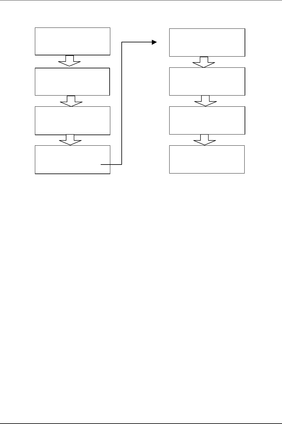
1.5.2 QAM Modulator/IF Upconverter
INTERLEAVE
RAM
QAM
ENCODER
NCO DIGITAL
POT
OCXO
12.8 MHz
FPGA
FPGA
EEPROM
uC
EEPROM
MICRO
CONTROLLER
LEVEL
TRANSLATOR
RS232
TRANSLATOR
QAM
DECODER
INTERLEAVE
RAM
RATE CONVERTER
PLL FIFO
SPI
IF
SYNTH IF
STATUS
IF OUT
IF REF
CLK OUT
TRUNK
I/O
TXD
BUS
DATA & CLK
IN
BUS
REF CLK
OUT
BUS
I2C IN
RXD
IF IN
AGC
BUS
DATA & CLK
OUT
DEBUG
LED
STATUS
REF CLK
NO
CONNECTION
uC BUS
LEGEND
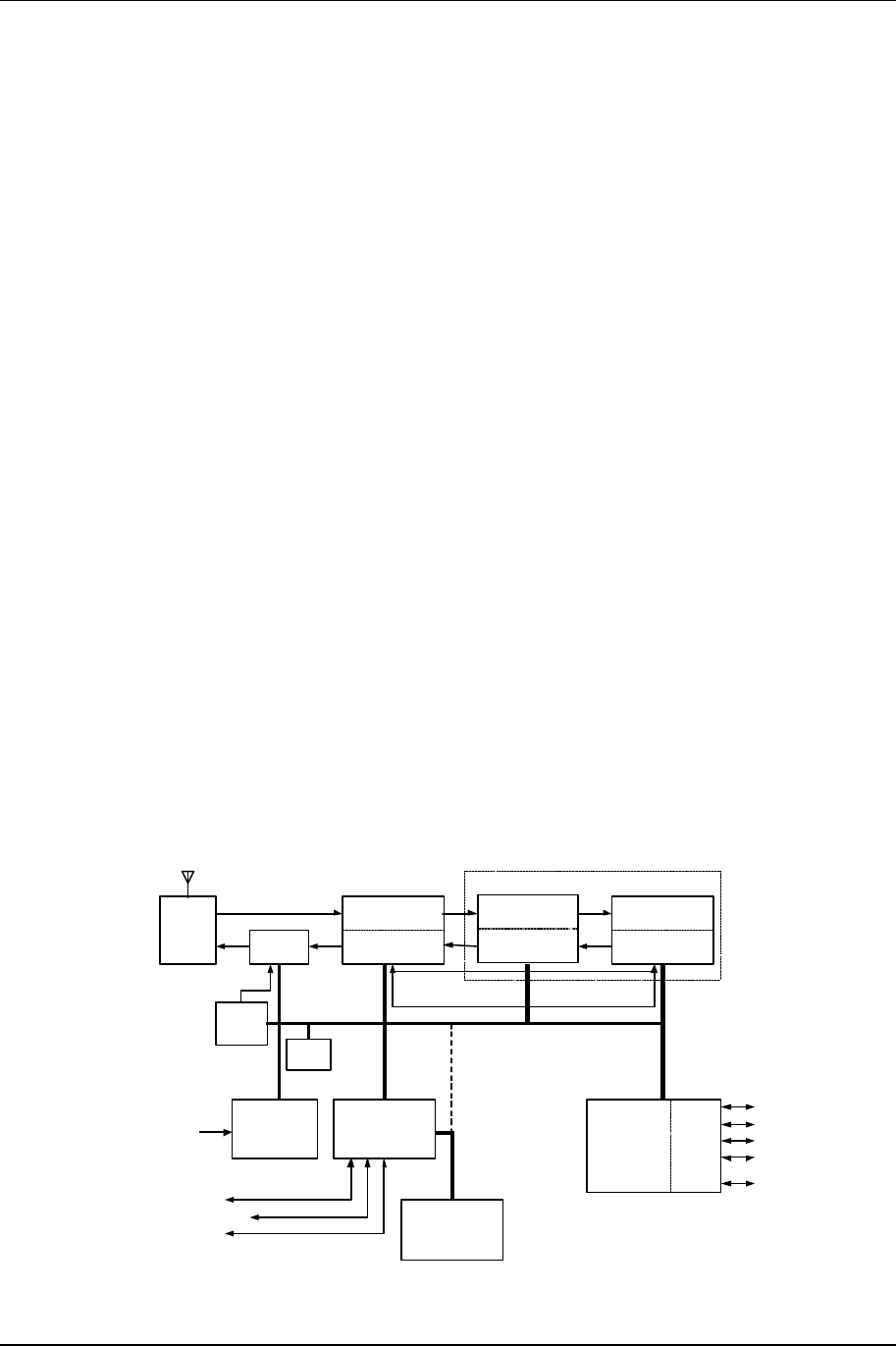
Figure 1-14. QAM Modem Block Diagram
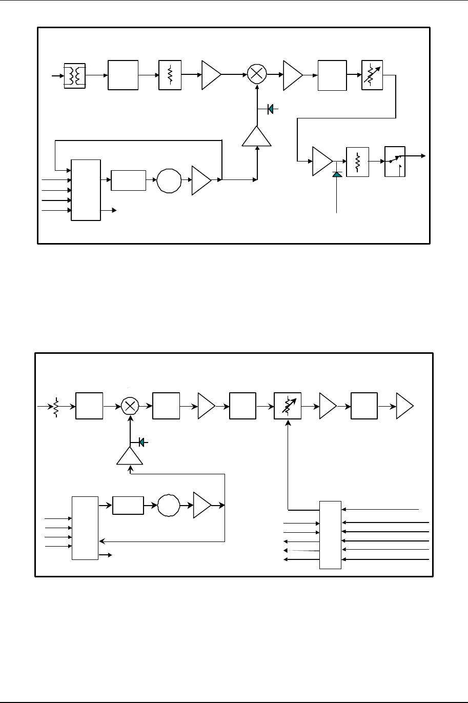
The QAM (Quadrature Amplitude Modulation) Modulator is the transmit portion of the QAM
Modem card. The QAM Modem also houses the IF Up/Down Converter. The QAM Modulator
utilizes the upconverter portion of the IF daughter card.
The QAM Modulator accepts the aggregate data stream via the backplane (see Figure 1-14
above). The module performs modulation at a carrier frequency of 6.4 MHz, adding FEC
(Forward Error Correction) bits while interleaving the blocks of data. The result is a very
spectrally efficient, yet robust linear modulation scheme. This process requires an ultra-stable
master clock provided by an OCXO (oven controlled crystal oscillator) that is accurate to within
0.1 ppm.
System Specifications & Description 1-8
602-95555-01 Rev A NXE1-20 Digital Radio
BPF
70 MHz
BPF
6.4 MHz
IF Output
70 MHz
-10 dBm
PLL
Loop
Filter VCO
76.4 MHz PLL
Data
Clk
Enbl
Ref
IF Input
6.4 MHz
-20 dBm
Synth Level
Synth
Lock
Exciter
Level
Figure 1-15. IF Upconverter Block Diagram
The resultant carrier is translated up to 70 MHz by the IF Upconverter (see Figure 1-15). This is
accomplished by a standard mixing of the carrier with a phase-locked LO. A 70 MHz SAW filter
provides an exceptional, spectrally-clean output signal.
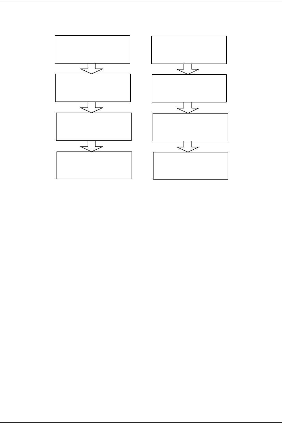
1.5.3 RF Upconverter
12.8 MHz Ref Osc
BPF
70 MHz IF
Input
uP
RFA Fwd Pwr Level
IPA Level
Synth Level
Temp Sense
Synth Lock
RF Output
TX ALC
BPF
70 MHz BPF
Diplexer
NMS
Synth Data
Synth Enbl
PLL
Loop
Filter VCO
PLL
Synth Lock
Synth Level
Data
Clk
Enbl
Ref
RFA Rev Pwr Level
Synth Clk
Figure 1-16. RF Upconverter Block Diagram
The IF output carrier of the IF Upconverter daughter card is fed to the transmit portion of the RF
Module via an external (rear panel) semi-rigid SMA cable. This module performs the necessary
upconversion to the RF carrier (see Figure 1-16). There is an on-board CPU for independent
control of the critical RF parameters of the system.
1-9 System Specifications & Description
NXE1-20 Digital Radio 602-95555-01 Rev A
Since this is a linear RF processing chain, an automatic leveling control loop (ALC) is
implemented here to maintain maximum available power output (and therefore maximum system
gain). The ALC monitors the PA forward power (FWD) output sample, and controls the
upconverter gain per an algorithm programmed in the CPU. The ALC also controls the power-up
RF conditions of the transmitter output.
1.5.4 Power Amplifier (PA)
The Power Amplifier (PA) is a separate module that is mounted to a heat sink and is fan-cooled
for reliable operation (see Figure 1-17). The PA is a design for maximum linearity in an amplitude
modulation-based system.
1.5.5 RF Downconverter
BPF Diplexer
70 MHz
RF Input
RF AGC
IF Amp
IF Output
70 MHz
to QAM
Demod
Preamp
ALC
Loop Amp
ALC
Det
Atten
BPF
70 MHz
PLL
Loop
Filter VCO
PLL
Synth
Lock
Data
Clk
Enbl
Ref
ALC Control
12.8 MHz Ref Osc
uP
Synth Level
Synth Lock
NMS
Synth Clk
Synth Data
Synth Enbl
Figure 1-18. RF Downconverter Block Diagram
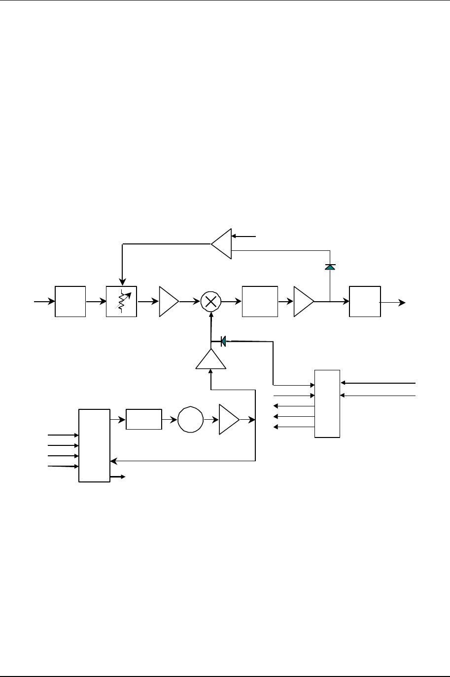
The receiver handles the traditional RF to IF conversion from the carrier to 70 MHz (see Figure 1-
18). Considerations are given to image rejection, intermodulation performance, dynamic range,
agility, and survivability. A separate AGC loop was assigned to the RF front end to prevent
intermodulation and saturation problems associated with reception of high level undesirable
interfering RF signals resulting from RF bandwidth that is much wider than the IF bandwidth. The
linear QAM scheme is fairly intolerant of amplifier overload.
System Specifications & Description 1-10
602-95555-01 Rev A NXE1-20 Digital Radio
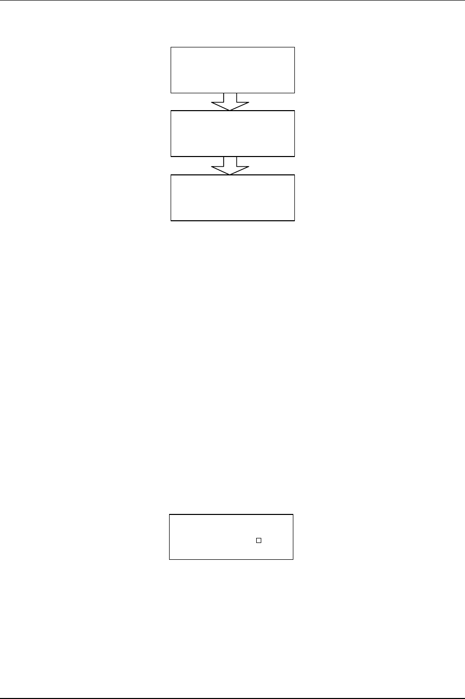
1.5.6 QAM Demodulator/IF Downconverter
IF Input
70 MHz
BPF
70 MHz
BPF
6.4 MHz
AGC Control
PLL
Loop
Filter VCO
76.4 MHz PLL
Data
Clk
Enbl
Ref
IF Output
6.4 MHz
-10dBm
Synth Level
Synth
Lock
Figure 1-19. IF Downconverter Block Diagram
The QAM (Quadrature Amplitude Modulation) Demodulator is the receive portion of the QAM
Modem card. The QAM Modem also houses the IF Up/Down Converter. The QAM Demod
utilizes the downconverter portion of the IF daughter card.
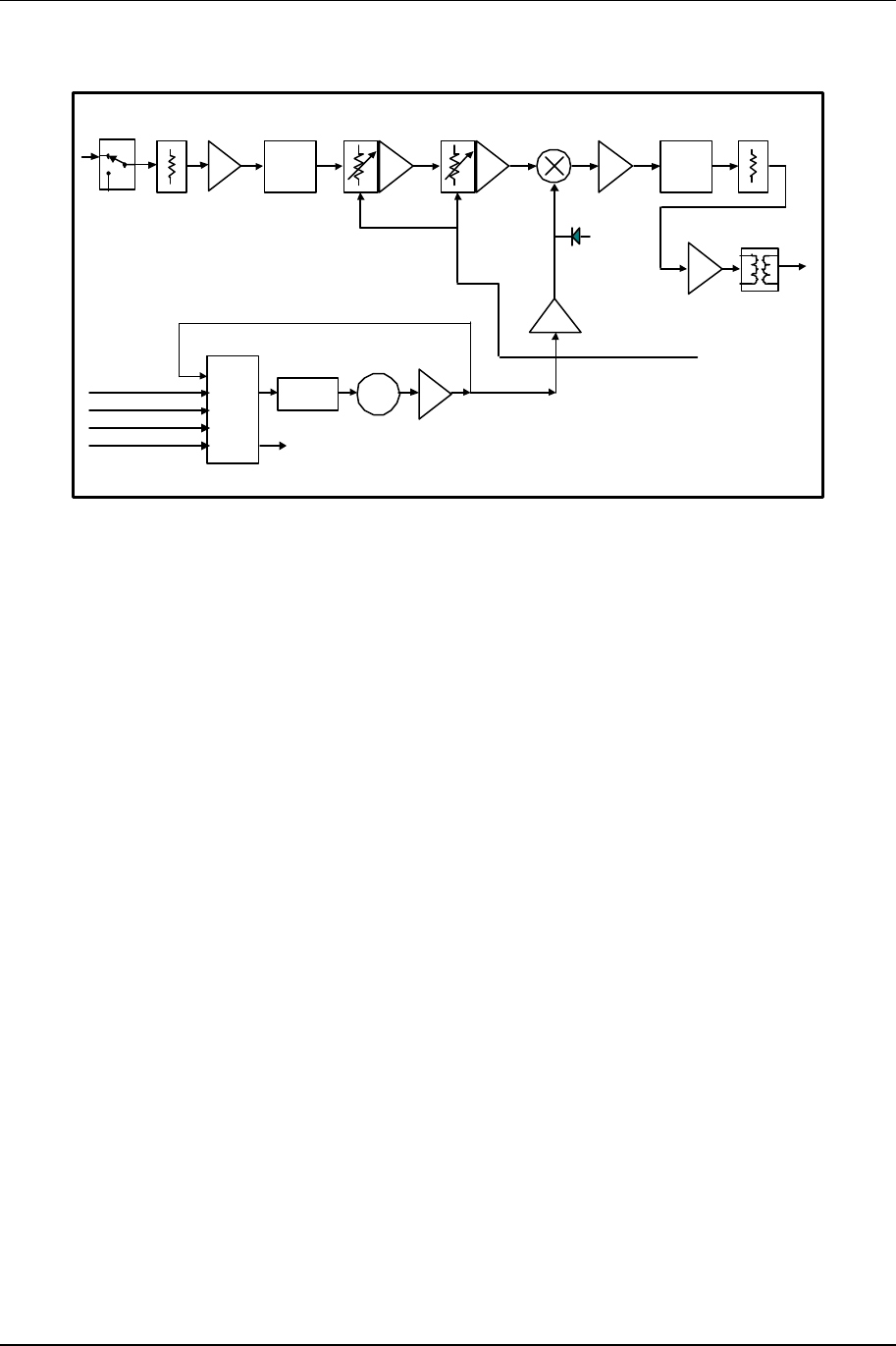
The IF Downconverter receives the 70 MHz carrier from the receiver portion of the RF Module via
an external semi-rigid cable and directly converts the carrier to 6.4 MHz by mixing with a low-
noise phase-locked LO (see Figure 1-19). System selectivity is achieved through the use of a 70
MHz SAW filter.
The QAM Demod receives and demodulates the 6.4 MHz carrier (see Figure 1-16). The
demodulation process includes the FEC implementation and de-interleaving that matches the
QAM modulator in the transmitter, and the critical “data assisted recovery” of the clock. This
process requires an ultra-stable master clock provided by an OCXO (oven controlled crystal
oscillator).
The output is an aggregate data stream that is distributed to the trunk port for if the data
input/output is out of the Modem, or to the backplane for connection to the multiplexer connected
on the backplane.

NXE1 Digital Radio 602-13068-01 Rev A
2 Installation
2.1 Unpacking
The following is a list of all included items.
Description Quantity
Digital Radio (3RU chassis) 1
Rack Ears (with hardware) 4
Extender Card (Universal QAM) — optional 1
Power Cord (IEC 3 conductor for AC, 2-wire for DC) 2
Manual ( or Soft copy on a CD) 1
Test Data Sheet (customer documentation) 1
Be sure to retain the original boxes and packing material in case of return shipping. Inspect all
items for damage and/or loose parts. Contact the shipping company immediately if anything
appears damaged. If any of the listed parts are missing, call the distributor or the factory
immediately to resolve the problem.
2.2 Notices
CAUTION
DO NOT OPERATE UNITS WITHOUT AN ANTENNA, ATTENUATOR, OR LOAD CONNECTED
TO THE ANTENNA PORT. DAMAGE MAY OCCUR TO THE TRANSMITTER DUE TO
EXCESSIVE REFLECTED RF ENERGY.
ALWAYS ATTENUATE THE SIGNAL INTO THE RECEIVER ANTENNA PORT TO LESS THAN
3000 MICROVOLTS. THIS WILL PREVENT OVERLOAD AND POSSIBLE DAMAGE TO THE
RECEIVER MODULE
WARNING
HIGH VOLTAGE IS PRESENT INSIDE THE POWER SUPPLY MODULE WHEN THE UNIT IS
PLUGGED IN. REMOVAL OF THE POWER SUPPLY CAGE WILL EXPOSE THIS POTENTIAL
TO SERVICE PERSONNEL. TO PREVENT ELECTRICAL SHOCK, UNPLUG THE POWER
CABLE BEFORE SERVICING. UNIT SHOULD BE SERVICED BY QUALIFIED PERSONNEL
ONLY.
Installation 2-2
602-95555-01 Rev A NXE1-20 Digital Radio
PRE-INSTALLATION NOTES
Always pre-test the system on the bench in its intended configuration prior to installation at a
remote site. Avoid cable interconnection length in excess of 1 meter in strong RF environments.
We highly recommend installation of lightning protectors to prevent line surges from damaging
expensive components.
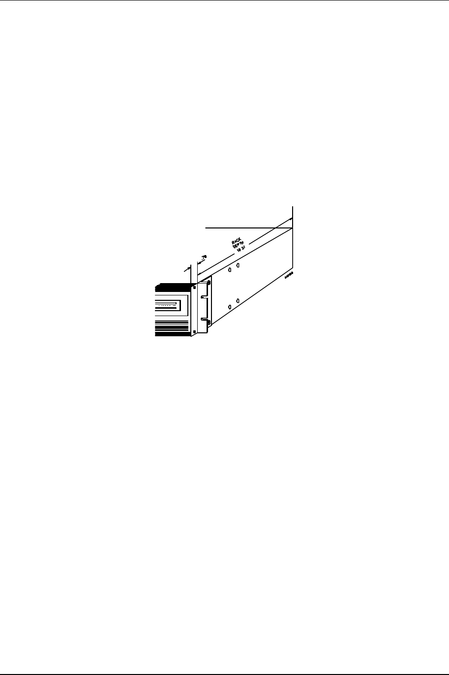
2.3 Rack Mount
The product is normally rack-mounted in a standard 19” cabinet. Leave space clear above (or
below) the unit for proper air ventilation of the card cage. The rack ears are typically mounted as
shown in Figure 2-1. Other mounting methods are possible by changing the orientation of the
rack ears.
Figure 2-1.NXE1-20 Typical Rack Mount Bracket Installation
2.4 Duplexer: Internal/External
Various duplexers, both internal and external, can be utilized. For current duplexers utilized with
the radios, please see the Appendix.
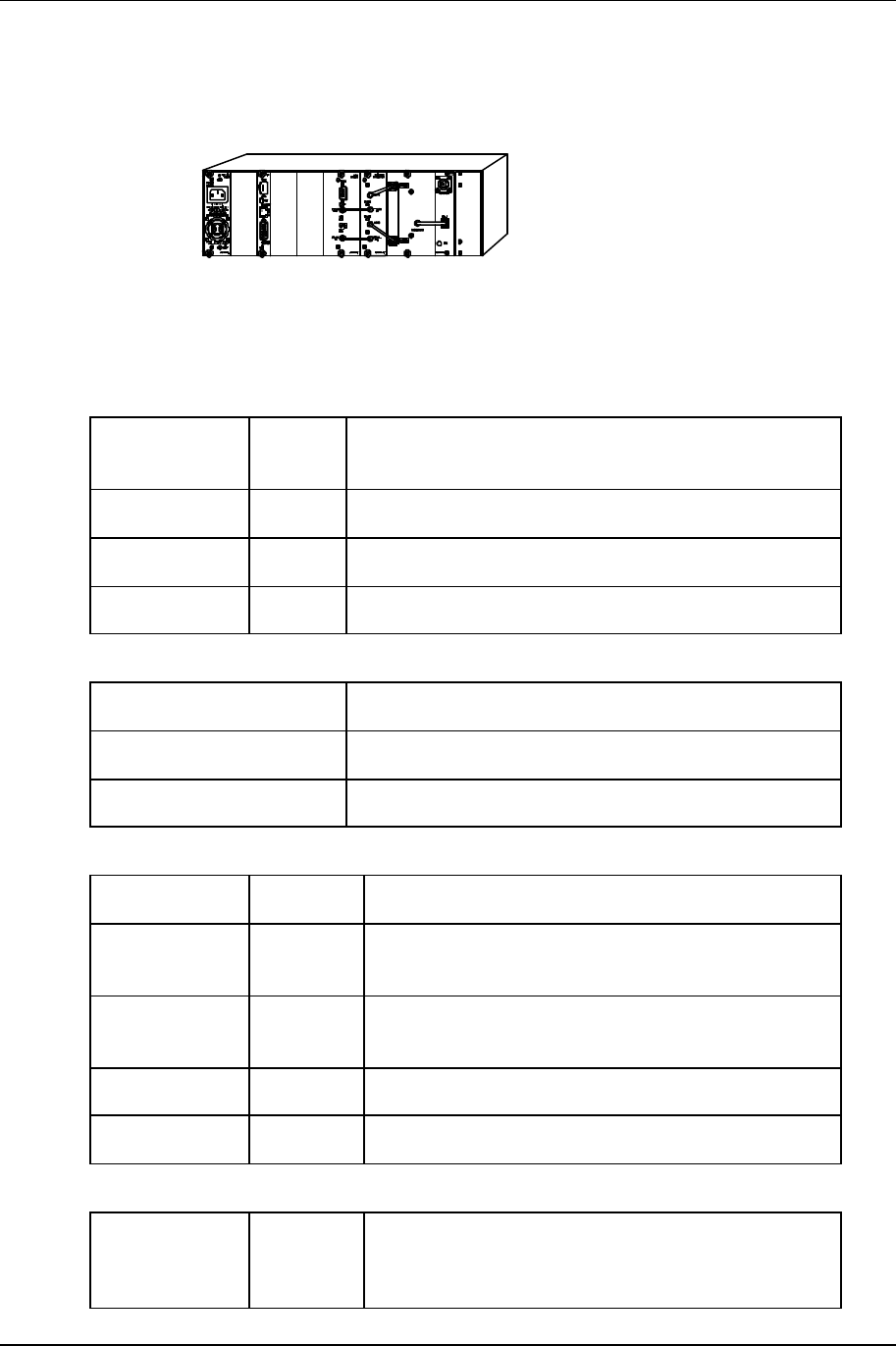
2.5 Rear Panel Connections & Indicators
Please refer to the Figure 2-2 for a pictorial of a typical product rear panel (internal duplexer).
Following is a descriptive text of the connections and LED indicators.
2-3 Installation
NXE1-20 Digital Radio 602-95555-01 Rev A
Figure 2-2.NXE1-20 Rear Panel Connections
Power Supply:
Inputs: AC: Universal Input, 100-240V, 50/60 Hz; IEC 3
conductor
DC: 24v/48v (Isolated Input); 2 pin socket (custom)
Status LED: +12V: Green LED indicates +12 volt supply OK
+5V: Green LED indicates +5 volt supply OK
NMS Card
I/O Port: RS232 PC access; 9 pin D-sub (female)
Reset Switch: Activates hard system reset
Status LED: Green LED Indicates CPU OK
QAM Modem
I/O Ports: TRUNK: Data I/O 15pin D-sub (female) HD
RF
Connectors: 70 MHz
OUT: SMA (female); Modulator output
70 MHz
IN: SMA (female); Demod input
Status LED: MOD: GREEN indicates Modulator Lock
DEMOD: GREEN indicates Demod Lock
Up/Down Converter Module
RF
Connectors: TO PA: SMA (female), Upconverter output to be applied
to linear Power Amplifier module (internal to
radio).

Installation 2-4
602-95555-01 Rev A NXE1-20 Digital Radio
70 MHz
IN: SMA (female), Modulated IF input from QAM
Modulator.
RF IN: SMA (female), Receiver input.
70 MHz
OUT: SMA (female); Downconverter output to
Modulator input
Status LED: TX
LOCK: GREEN indicates TX AFC LOCK
Flashing RED indicates LOSS OF TX LOCK
RX
LOCK: GREEN indicates RX AFC LOCK and strong RX
signal
YELLOW indicates RX AFC LOCK and nominal
RX signal
RED (continuous) indicates RX AFC LOCK and
weak RX signal
RED (flashing) indicates LOSS OF RX LOCK
RF I/O Panel
RF
Connectors: ANTENNA: Type N (female), RF cabling from internal PA
module.
PA IN: SMA (female), RF cabling to internal PA
module.
RX OUT: SMA (female), RF cabling from internal
duplexer.
SEMI-RIGID CABLE
Ensure that the cables are secure and tightly attached.
Check for any damage (kinks or breaks in the copper sheath).
2.6 Power Requirements
2.6.1 Power Supply Card Slot Details
The leftmost slot in the NXE1-20 card cage (as viewed from the rear of the unit) is designated as
the “PRIMARY A” power supply. The main bus voltages (+5 and +/-12) are summed in the
backplane and provide the supply the plug-in modules.
NOTE: The front panel LCD screen displays the system supply voltages and the
nomenclature follows the physical location of the power supply modules.
2-5 Installation
NXE1-20 Digital Radio 602-95555-01 Rev A
2.6.2 AC Line Voltage
The NXE1-20 uses a high reliability, universal input switching power supply capable of operating
within an input range of:
100 - 240 VAC; 50/60 Hz
The power supply module is removable from the unit and a perforated cage protects service
personnel from high voltage. The power supply is fan cooled due to high power consumption by
the PA.
CAUTION
High voltage is present when the unit is plugged in. To prevent electrical shock, unplug the power
cable before servicing. Power supply module should be serviced by qualified personnel only.
2.6.3 DC Input Option
An optional DC input power supply is available for the NXE1-20; using high reliability, DC-DC
converter(s) capable of operation within the following input ranges (dependent upon nominal input
rating):
Nominal DC Input Operating Input Range
24 Volt: 20 – 28 VDC
48 Volt: 32 – 64 VDC
The DC input is isolated from chassis ground and can be operated in a positive or negative
ground configuration. The power supply module is removable from the unit and no high voltages
are accessible.
2.6.4 Fusing
For AC modules, the main input fuse is located on the switching power supply mounted to the
carrier PC board and the protective cage may be removed for access to the fuse.
For DC modules, all fusing is located on the carrier PC board.
Always replace any fuse with same type and rating. Other fuses are present on the board, and
are designed for output fail-safe protection of the system. All output fuse values are printed on
the backside of the PC board to aid in replacement.
NOTE: If a fuse does blow in operation, investigate the possible cause of the failure prior to
replacing the fuse, as there is adequate built-in protection margin.
Installation 2-6
602-95555-01 Rev A NXE1-20 Digital Radio
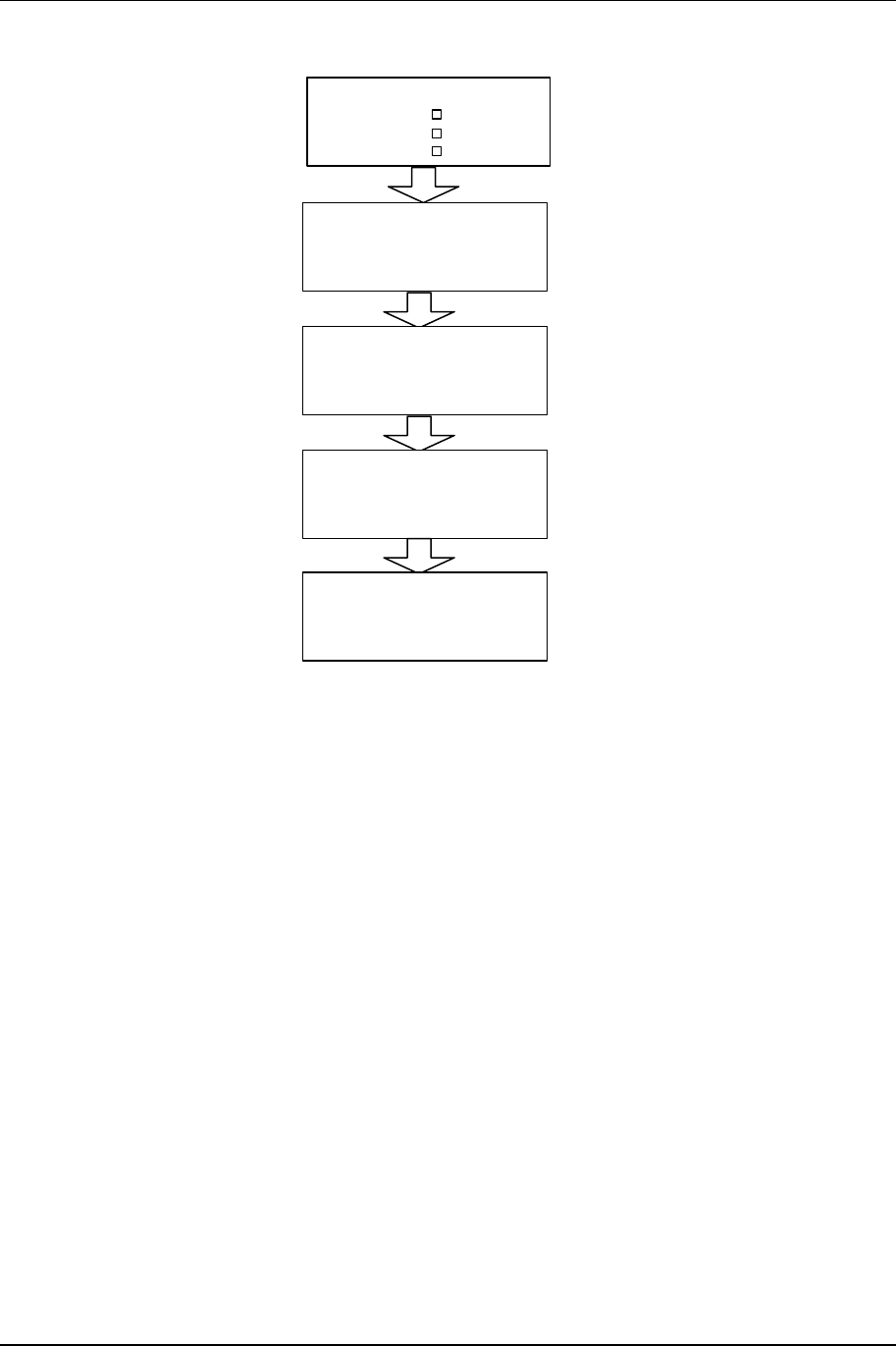
2.7 Power-Up Setting
As shipped, the NXE1-20 will radiate into the antenna upon power-up, THIS ASSUMES THAT
THE ANTENNA LOAD IS GOOD (LOW VSWR). If the VSWR of the load causes a high reverse
power indication at the PA, the red VSWR LED will light and the transmitter will cease radiating.
This is called the “AUTO” setting in the QAM RADIO CONTROL screen (see below).
The LCD screen (“QAM RADIO TX CONTROL”) selects the power-up state and controls the
radiate function of the TX unit.
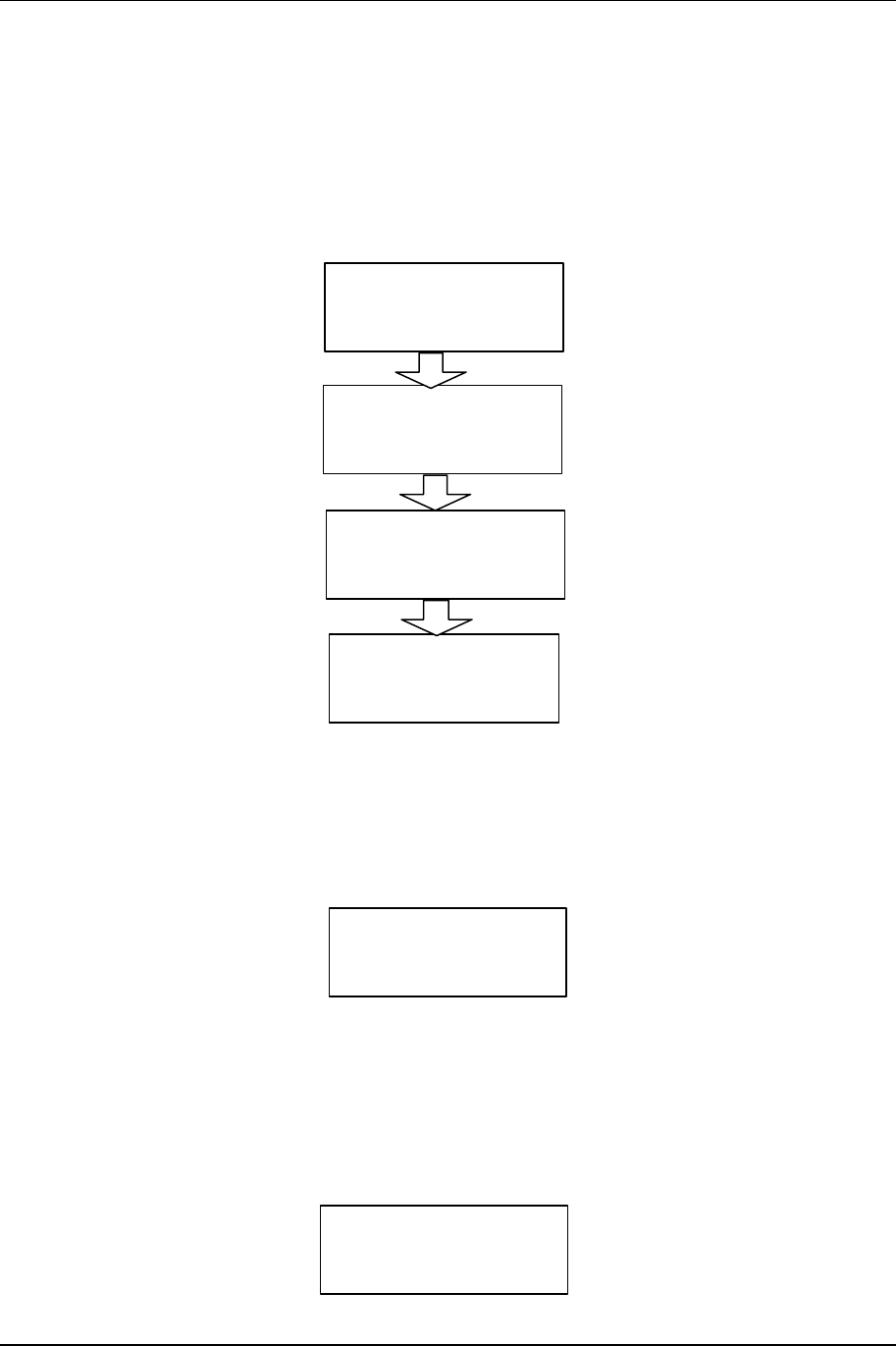
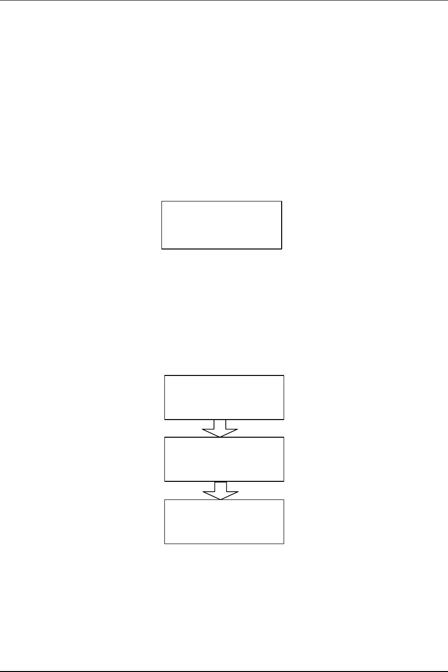
Go to the MAIN MENU:
METER
QAM RADIO
NXE1 Main Menu
SYSTEM
ALARMS/FAULTS
Scroll
Scroll to QAM Radio, press ENTER.
Select Launch Screen for CONTROL TX, press ENTER:
CONTROL
QAM Radio Launch
TXA
TX Radiate
QAM Radio TX Control
AUTO
Verify the AUTO setting.
AUTO: Transmitter will protect its PA by “folding back” the ALC under bad
load VSWR condition (default setting)
ON: Transmitter will remain in radiate at full power under all antenna
port conditions (not recommended).
OFF: Transmitter in standby mode.
2-7 Installation
NXE1-20 Digital Radio 602-95555-01 Rev A
2.8 Data Interface
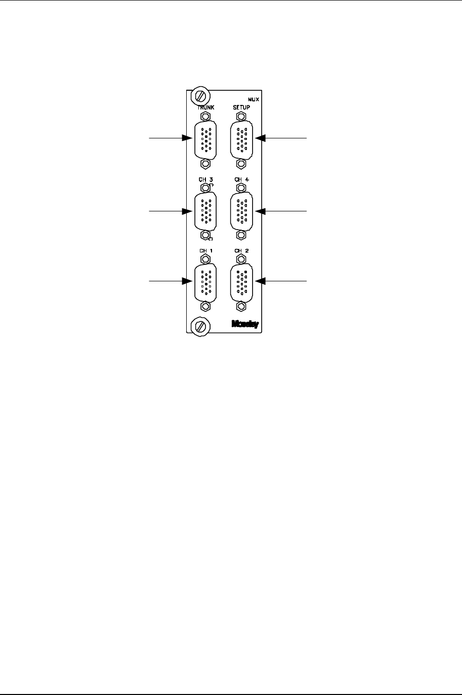
2.8.1 4xE1/T1 MUX Channel Configurations
Trunk I/O Async Data Channel
Channel 3/4 (E1/T1)Channel 1/2 (E1/T1)
Aux Channel 1 Aux Channel 2
Figure 2-3. 4XE1/T1 MUX Panel
The 4xE1/T1 MUX is a high speed card (up to 8 MBPS) that has a total of 7 ports. Table 2-1
summarizes the capabilities.

Installation 2-8
602-95555-01 Rev A NXE1-20 Digital Radio
Table 2-1.NXE1-20 4xE1/T1 MUX Data Channel Configurations
Chnl Data
Rate
4xE1
(BPS)
Data
Rate
4xT1
(BPS)
Data
Rate
2xE1
(BPS)
Data
Rate
2xT1
(BPS)
Data
Rate
1xE1
(BPS)
Data
Rate
1xT1
(BPS)
Inter-
face
1 2.048 K 1.544 K 2.048 K 1.544 K 2.048 K 1.544 K G.703,
DSX-1
2 2.048 K 1.544 K 2.048 K 1.544 K --- --- G.703,
DSX-1
3 2.048 K 1.544 K --- --- --- --- G.703,
DSX-1
4 2.048 K 1.544 K --- --- --- --- G.703,
DSX-1
* Aux1 128 K 96 K 64 K 48 K 32 K 24 K V.35,
RS449
* Aux2 128 K 96 K 64 K 48 K 32 K 24 K V.35,
RS449
ASYNC
Data 9600 7200 4800 3600 2400 1800 RS232
* AUX Channels 1-2 can be combined to form 2xCh.1 or 2xCh.2 (i.e., in 4xE1 mode, AUX could
be a single channel of 256 KBPS)
Table 2-2.NXE1-20 Voice/Data MUX Channel Configurations
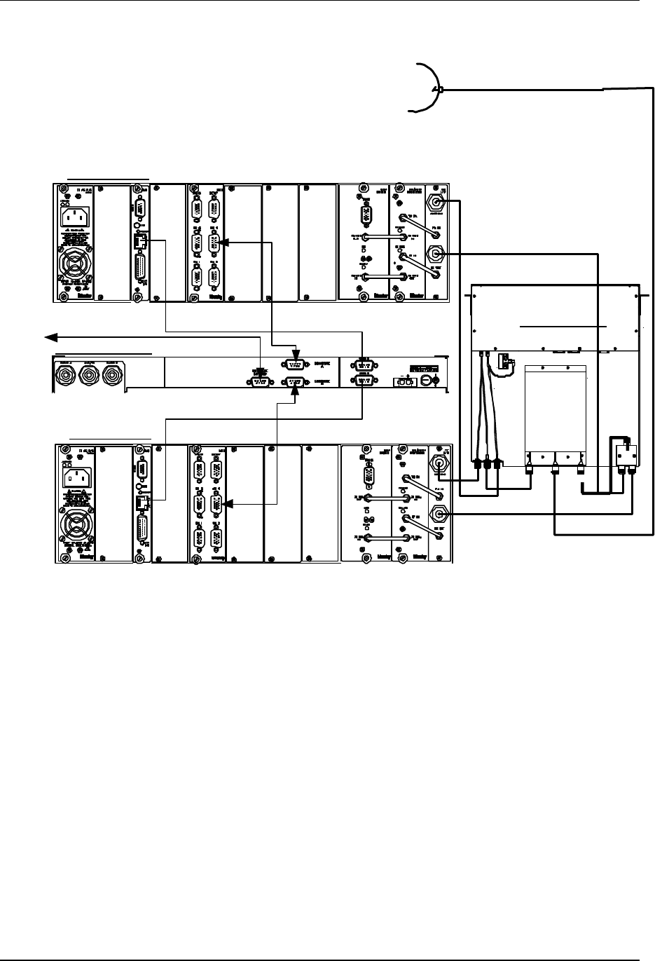
2.9 Hot Standby (Protected) Configuration
The NXE1-20 may be installed in a hot standby (protected) configuration. This consists of
twoNXE1-20 chassis with a TP64 transfer panel (Figure 2-5)
Transfer Panel Connection
The usual hot standby configuration uses an external duplexer. This minimizes RF losses and
provides independent TX and RX module switching. A duplexer should already be mounted on
the TP64 chassis. Alternatively, rack mounted duplexers (typical for tighter channel spacings)
may be provided. The connections are the same, although the physical location is different.
A power divider (used to split the signal equally to two receivers) is required in this mode. The
input to the power divider connects directly to the duplexer with an N-N (male) adapter.
2-9 Installation
NXE1-20 Digital Radio 602-95555-01 Rev A
See Figure 2-5 for installation details.
ANTENNA
RJ45
RJ45
DATA
DATA
DATA
TP64 Top View
TP64 Rear Panel
NXE1 Radio B
NXE1 Radio A
Figure 2-5.NXE1-20 Hot Standby – with Transfer Panel
2.9.1 Hot/Cold Standby Modes
Hot Standby ( *preferred)
Hot standby leaves both transmitters in the RADIATE ON condition, and the transfer logic
controls the RF relay to select the active transmitter, thereby decreasing switchover time. This is
the preferred operating mode.
Cold Standby
Cold standby can be used in situations where lower power consumption is a priority. In this
mode, the transfer logic will control the RADIATE function of each transmitter, turning the RF
output ON (in tandem with the RF relay) as required for switching. This will increase switching
time and a corresponding increase in data loss during the switchover.
Installation 2-10
602-95555-01 Rev A NXE1-20 Digital Radio
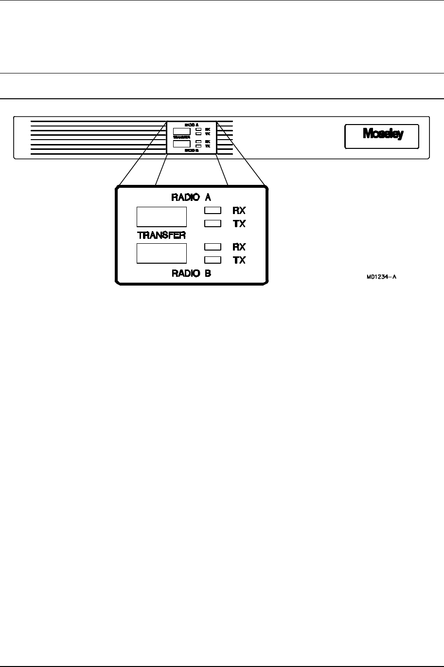
2.9.2 Hot Standby Control using the Moseley TP64
2.9.2.1 TP64 Front Panel Controls and Indicators
Note: See the following section for a detailed description of the Master/Slave logic implemented
in the TP64.
Figure 2-7. TP64 Front Panel
LED Indicators
Green: The indicated module is active, and that the module is performing within
its specified limits.
Yellow: The indicated module is in standby mode, ready and able for back-up
transfer.
Red: There is a fault with the corresponding module. It is not ready for
backup, and the TP64 will not transfer to that module.
TRANSFER Switches
The RADIO A and RADIO B transfer switches cause the selected radio to become active, and the
Master. See Section 3.4 (following) for further details.
2.9.2.2 Master/Slave Operation & LED Status
The TP64 operates in a Master/Slave logic mode. In the power up condition, the Master is
RADIO A. This means that RADIO A is the default active unit. The following logic applies to hot
or cold standby, external or internal duplexer configurations.
2-11 Installation
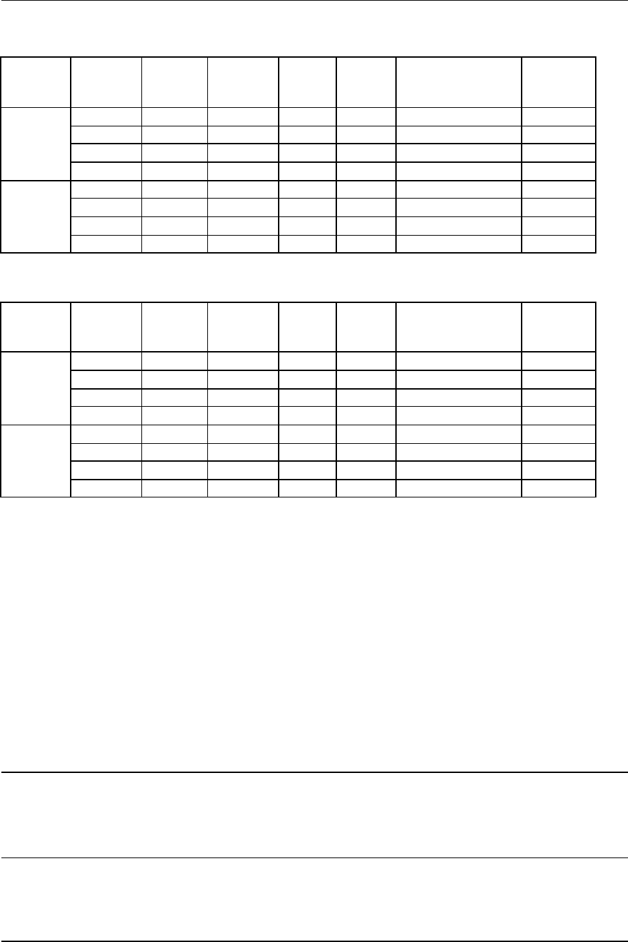
NXE1-20 Digital Radio 602-95555-01 Rev A
Table 2-3. TP64 Transmitter Master/Slave Logic
Selected
Master TXA
Status TXB
Status TXA
LED TXB
LED Active TX TX Relay
Position
A OK OK GRN YEL A A
A OK FAIL GRN RED A A
A FAIL OK RED GRN B B
A-Master
Logic
A FAIL FAIL RED RED N/A A
B OK OK YEL GRN B B
B OK FAIL GRN RED A A
B FAIL OK RED GRN B B
B-Master
Logic
B FAIL FAIL RED RED N/A B
Table 2-4. TP64 Receiver Master/Slave Logic
Selected
Master RXA
Status RXB
Status RXA
LED RXB
LED Active RX
RX Data &
Clk
A OK OK GRN YEL A A
A OK FAIL GRN RED A A
A FAIL OK RED GRN B B
A-Master
Logic
A FAIL FAIL RED RED N/A None
B OK OK YEL GRN B B
B OK FAIL GRN RED A A
B FAIL OK RED GRN B B
B-Master
Logic
B FAIL FAIL RED RED N/A None
A-Master Logic (default power-up):
If RADIO A is “good”, the TP64 will remain in RADIO A position, regardless of RADIO B’s status.
If RADIO A fails, the TP64 will switch to RADIO B (assuming that RADIO B is “good”)
If RADIO A then returns to a “good” condition, the TP64 will switch back to RADIO A (the default
Master)
Manual Switchover to B-Master Logic
The front panel switch on the TP64 can be used to manually force the system to a new Master.
By pressing the RADIO B button, RADIO B now becomes the Master, and the TP64 will
switchover to RADIO B (assuming that RADIO B is “good”).
The default A-Master Logic will then switch to B-Master Logic, as outlined in Tables 2-3 and 2-4.
Note: Manual switching of the Master is often used to force the system over to the standby unit.
The user may want to put more “time” on the standby unit after an extended period of
service. In Hot Standby configurations, this will not buy the user anything in terms of
reliability. In Cold Standby, the “burn time“ is more significant, since the RF power
amplifier device operating life becomes a factor.
Installation 2-12
602-95555-01 Rev A NXE1-20 Digital Radio
2.9.2.3 NXE1-20 Software Settings
The full array of available settings for the Control and Configuration menus are located in Section
3—Operation of the Front Panel. Shown here are the applicable settings for redundant standby
systems.
Clock Settings
For proper operation, the clock settings (located in the QAM Radio/Config/Modem Menu) must be
set as follows:
QAM Interface
Intfc TRUNK
Tx In Clock
Clk Phase INVERTED
Rx Clock Out
Clk Phase NORMAL
Trunk Out
Clk Source
Clk Phase EXTERNAL
NORMAL
Control Settings
These settings configure the transmitter for hot (or cold) standby.
It is important that each NXE1-20 radio in the redundant pair is configured identically for proper
operation.
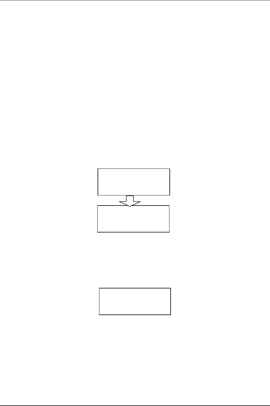
In the SYSTEM TRANSFER menu:
Transfer
Tx Transfer ______
Rx Transfer ______
Tx Transfer:
OFF: Turns Transmitter Transfer Mode OFF.
Rx Transfer:
OFF: Indicates the receivers are not switched.
In the QAM Radio TX Control menu:
QAM Radio Tx Control
TX Radiate ______
2-13 Installation
NXE1-20 Digital Radio 602-95555-01 Rev A
Tx Radiate:
ON: Configures the Transmitter to always RADIATE.
2.9.2.4 TP64 Settings
The TP64 software settings are contained in the internal firmware. Aside from the front panel
RADIO A/B Master Select (as described above), there are no user-configurable settings in the
TP64 unit.
2.9.3 Hot Standby Control with Single Unit
2.9.3.1 NXE1-20 Software Settings
The full array of available settings for the Control and Configuration menus are located in Section
3—Operations. Shown here are the applicable settings for single systems.
Clock Settings
All controls and indications can be found on the NXE1-20 front panel LCD display (located in the
QAM Radio/Config/ModA or ModB Menu).
QAM Interface
Intfc RADIO(BKPLN)
Tx In Clock
Clk Phase NORMAL
Control Settings
These settings configure the transmitter for hot (or cold) standby.
It is important that each NXE1-20 radio in the redundant pair is configured identically for proper
operation.
In the SYSTEM TRANSFER menu:
Transfer
Tx Transfer ______
Rx Transfer ______
Tx Transfer:
HOT: Configures the Transmitter for HOT STANDBY
operation.*(preferred)
COLD: Configures the Transmitter for COLD STANDBY operation.
Rx Transfer:
ON: Places the receivers in both active and transfer mode.
In the QAM Radio TX Control menu:

Installation 2-14
602-95555-01 Rev A NXE1-20 Digital Radio
QAM Radio Tx Control
TX Radiate ______
Tx Radiate:
AUTO: Software controls the RADIATE function.
2.10 Site Installation
The installation of the NXE1-20 involves several considerations. A proper installation is usually
preceded by a pre-installation site survey of the facilities. The purpose of this survey is to
familiarize the customer with the basic requirements needed for the installation to go smoothly.
The following are some considerations to be addressed (refer to Figure 2-8 for Site Installation
Details).
Before taking the product to the installation site verify that the interface connections are
compatible with the equipment to be connected. Also, locate the information provided by the path
analysis that should have been performed before ordering the equipment. At the installation site,
particular care should be taken in locating the product in an area where it is protected from the
weather and as close to the antenna as possible. Locate the power source and verify that it is
suitable for proper installation.
The Installations should only be performed by qualified technical personnel
only.
2.11 Antenna/Feed System
2.11.1 Antenna Installation
For compliance with FCC RF Exposure requirements the following has to be adhered to:-
1. All antenna installation and servicing is to be performed by qualified technical personnel
only. When servicing the antenna, or working at distances closer than those noted below,
ensure the transmitter has be disabled.
2. Typically, the antenna connected to the transmitter is a directional (high gain) antenna,
fixed-mounted on the side or top of a building, or on a tower. Depending upon the
application and the gain of the antenna, the total composite power could exceed 20 to
61watts EIRP. The antenna location should be such that only qualified technical
personnel can access it, and that under normal operating conditions the antenna
separation from the user is required to be located at the distance of 3.5meters or more.

2-15 Installation
NXE1-20 Digital Radio 602-95555-01 Rev A
EIRP at the antenna is calculated as follows:-
Transmit power – Cable loss + Antenna Gain = EIRP
Eg.
+31.1dBm – 6dB(for 100m LDF5-50A) +36dBi = 61.1Bmi
NXE1 Digital Radio 602-13068-01 Rev A
3 Front Panel Operation
3.1 Introduction
This section describes the front panel operation of the NXE1-20 digital radio/modem. This
includes:
• LCD display (including all screen menus)
• Cursor and screen control buttons
• LED status indicators
3.2 Front Panel Operation
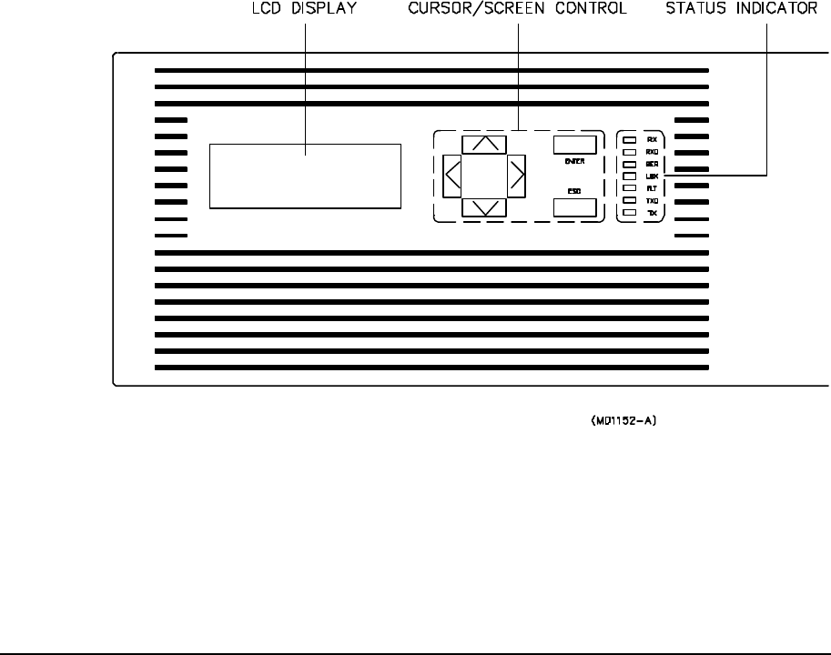
A picture of the NXE1-20 front panel is depicted in Figure 3-1 below.
Figure 3-1.NXE1-20 Front Panel
3.2.1 LCD Display
The Liquid Crystal Display (LCD) on the NXE1-20 front panel is the primary user interface and
provides status, control, configuration, and calibration functionality. The menu navigation and
various screens are explained in detail later in this section.
Front Panel Operation 3-2
602-95555-01 Rev A NXE1-20 Digital Radio
Backlight:
An automatic backlight is built-in to the LCD for better clarity under low-light conditions. This
backlight is enabled on power-up and will automatically turn off if there is no button activity by the
user. The backlight will automatically turn on as soon as any button is pressed.
Contrast Adjustment:
Internal adjustment on board (in back of front panel button PCB).
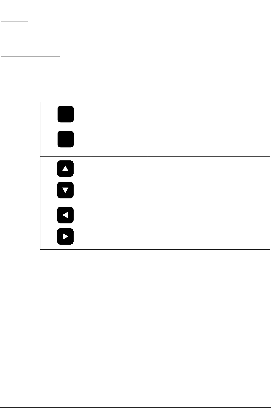
3.2.2 Cursor and Screen Control Buttons
The buttons on theNXE1-20 front panel are used for LCD screen interface and control functions:
ENT
<ENTER>
Used to accept an entry (such as a value,
a condition, or a menu choice).
ESC
<ESC> Used to “back up” a level in the menu
structure without saving any current
changes.
<UP>,<DOWN> Used in most cases to move between the
menu items. If there is another menu in
the sequence when the bottom of a menu
is reached, the display will automatically
scroll to that menu.
<LEFT>,<RIGHT> Used to select between conditions (such
as ON/OFF, ENABLED/DISABLED,
LOW/HIGH, etc.) as well as to increase or
decrease numerical values.

3-3 Front Panel Operation
NXE1-20 Digital Radio 602-95555-01 Rev A
3.2.3 LED Status Indicators
Table 3-1. LED Status Indicator Functions
LED Name Function
RX Receiver Green indicates that the receiver is enabled, the
synthesizer is phase-locked, and a signal is
being received.
RXD Receive Data Green indicates that valid data is being received.
BER Bit Error Rate Flashes red for each data error detected.
FLT Fault General fault light (red). Consult the STATUS
menus for out of tolerance conditions.
LBK Loopback Red indicates analog or digital loopback is
enabled.
TXD Transmit Data Green indicates the modem clock is phase-
locked and data is being sent.
TX Transmitter Green indicates the transmitter is radiating, and
the RF output (forward power) is above the
factory-set threshold.
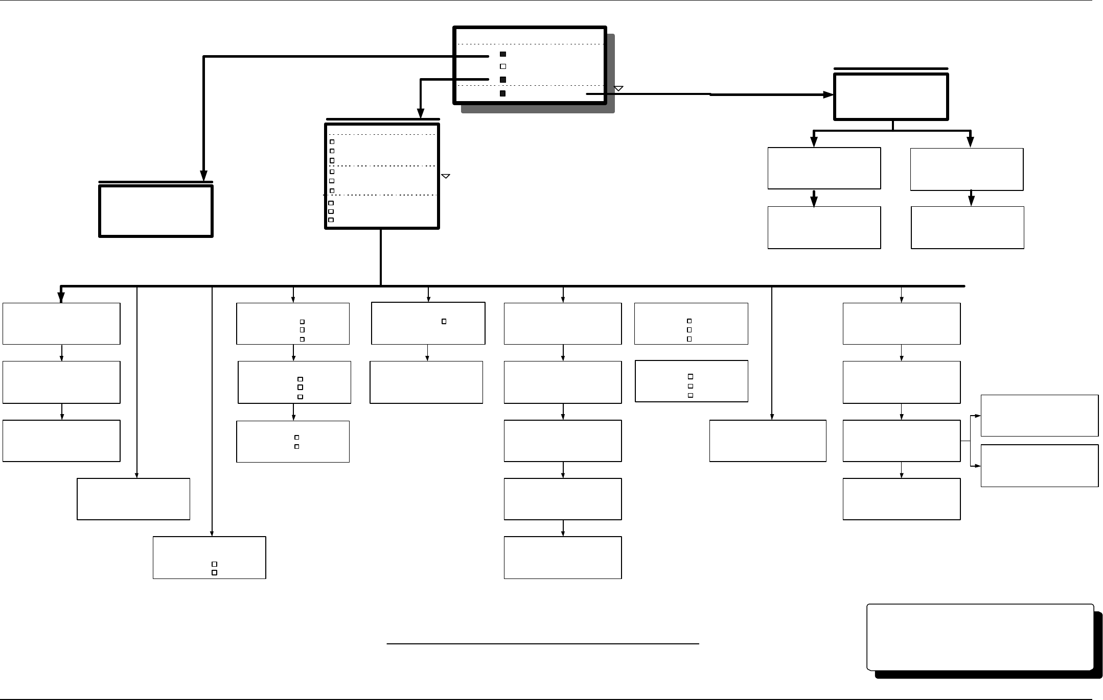
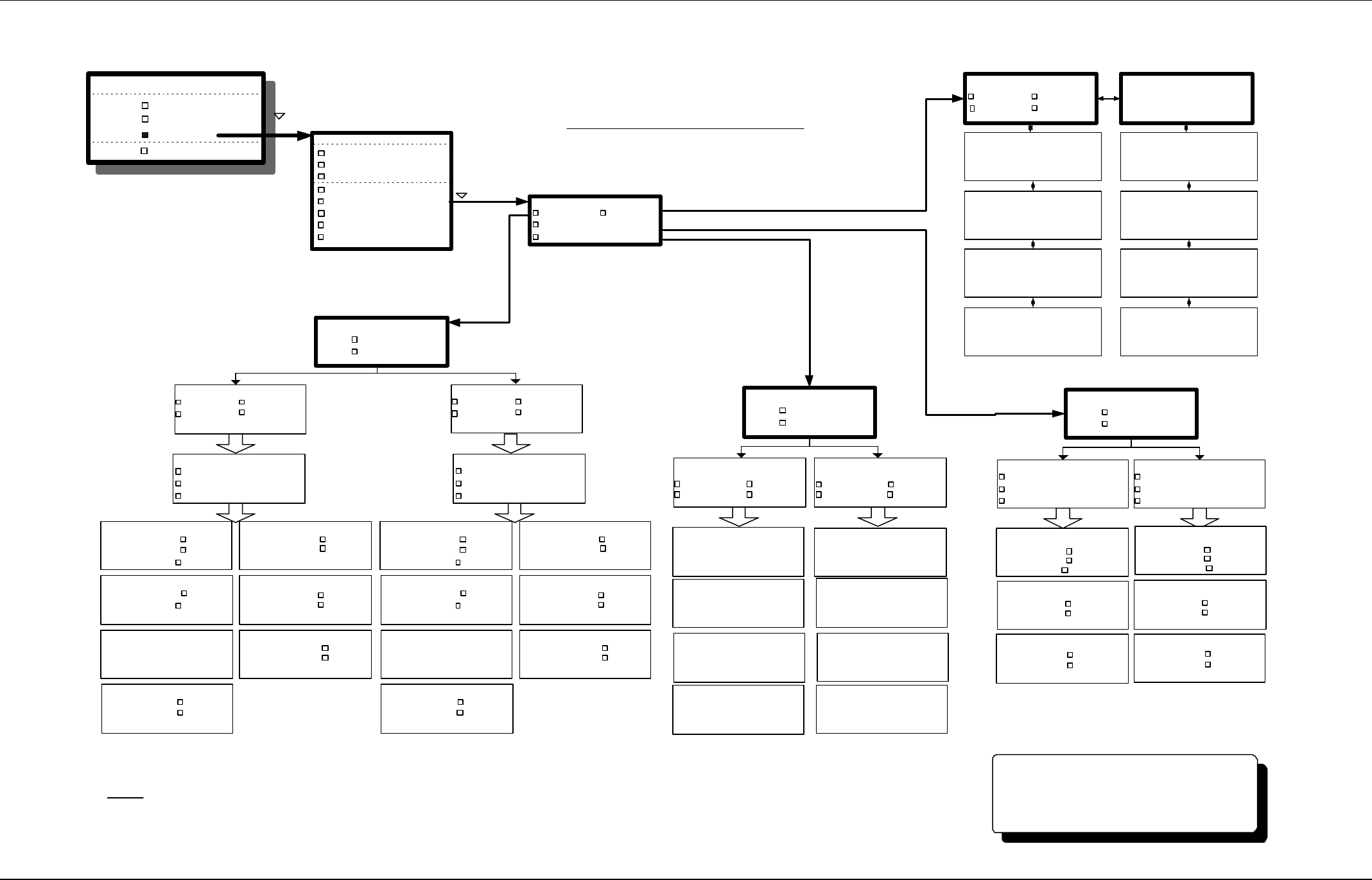
3.2.4 Screen Menu Tree Structure
Figures 3-2a, b and c, located on pages 3-7, 3-8, 3-9 and 3-10, show the tree structure of the
screen menu system. The figures group the screens into functional sets. There may be minor
differences in the purchased unit, due to software enhancements and revisions. The current
software revision may be noted in the SYSTEM sub-menu (under INFO).
In general, <ENTER> will take you to the next screen from a menu choice, <UP> or <DOWN> will
scroll through screens within a menu choice, and <ESC> will take you back up one menu level.
Certain configuration screens have exceptions to this rule, and are noted later in this section.
CAUTION
DO NOT change any settings in the CONFIGURE or CALIBRATE screens. The
security lock-out features of the software may not be fully implemented, and
changing a setting will most likely render the system non-operational!
Front Panel Operation 3-4
602-95555-01 Rev A NXE1-20 Digital Radio
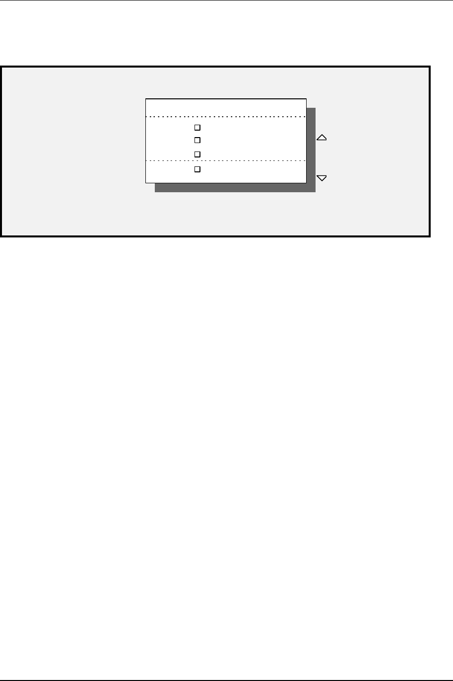
3.3 Main Menu
METER
QAM RADIO
NXE1 MAIN MENU
SYSTEM
ALARMS/FAULTS
Scroll
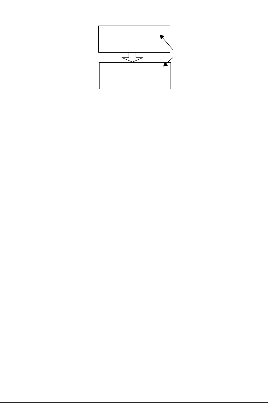
The main menu appears on system boot-up, and is the starting point for all screen navigation.
Unlike most other screens in the software, the main menu scrolls up or down, one line item at a
time.
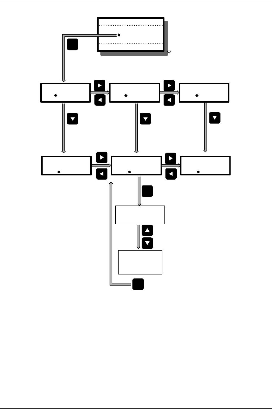
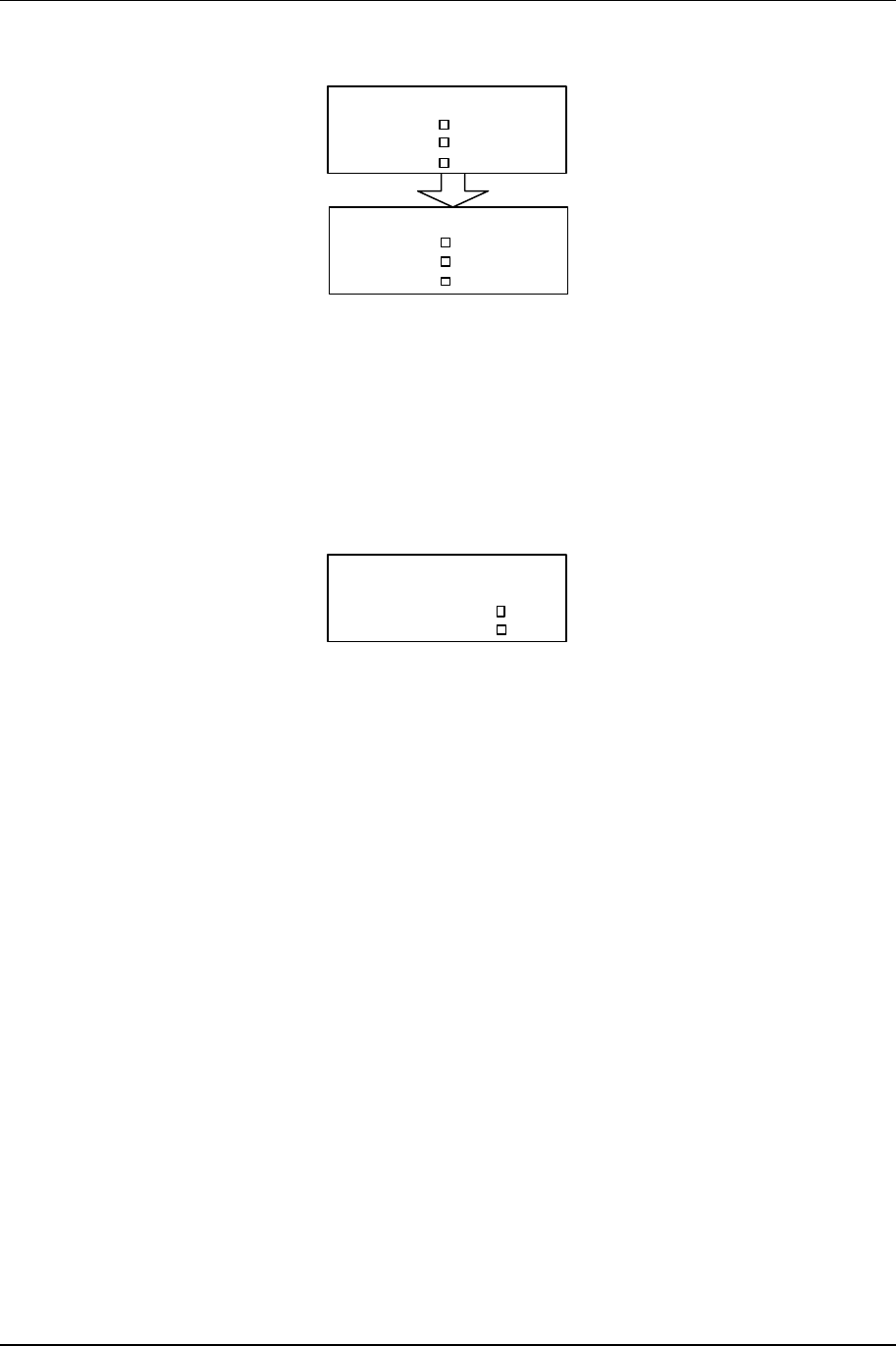
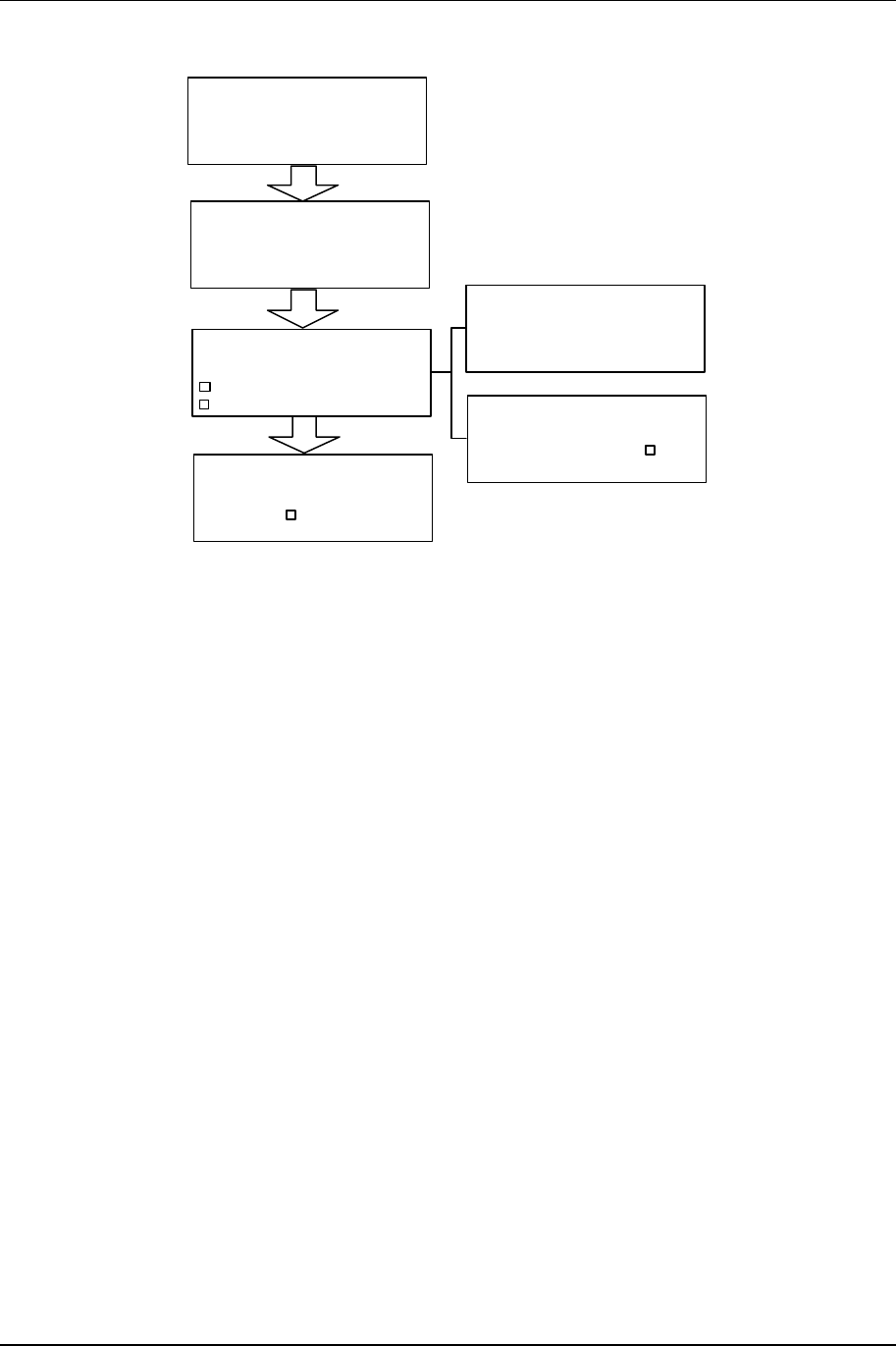
3.3.1 Launch Screens
The LAUNCH screen allows the user to quickly get to a particular screen within a functional
grouping in the unit. The logic is slightly different than other screens. Figure 3-3 below contains
a “Launch Screen Navigation Guide” to assist the user in locating the desired Radio screen.
3-5 Front Panel Operation
NXE1-20 Digital Radio 602-95555-01 Rev A
METER
QAM RADIO
NXE1 MAIN MENU
SYSTEM
ALARMS/FAULTS
Scroll
CONFIGURE
QAM Radio Launch
MODEM
STATUS
QAM Radio Launch
TX STATUS
QAM Radio Launch
RX
ENT
ENT
FreqA
QAM Radio TX Status
MHz
More Screens
(see Menu Flow
Diagram)
CONTROL
QAM Radio Launch
MODEM
STATUS
QAM Radio Launch
MODEM
STATUS
QAM Radio Launch
MODEM
Cycle through STATUS, CONTROL,
CONFIGURE choices:
Cycle through MODEM,
TX, RX choices:
TX STATUS chosen,
press ENTER to view.
Page down/up with
down or up arrow.
ESC Press ESCAPE to return to
previous levels.
Move cursor to
next line
Figure 3-3. Launch Screen Navigation Guide

Front Panel Operation 3-6
602-95555-01 Rev A NXE1-20 Digital Radio
This page is intentionally blank.
3-7 Front Panel Operation
NXE1 Digital Radio 602-13068-01 Rev A
Power Supply
Primary
+5VD
+15VD
AC
5.00 V
15.00 V
AUDIO DEC
CARD ID
Chnl Cd
MUX MUX0
CHC1
Basic Card Setup
QAM Modem
RF Tx QMA
TXA
CARD ID
Factory Calibrate
RADIO RX
QAM Modem
RADIO TX System
CARD ID
AUDIO ENC
RF RX RXA
ENC1
DEC1AUDIO DEC
(see Factory
Calibration
submenu)
System Information
SECURITY
FIRMWARE USER
Vx.xx
METER
Meter
Bargraph DECDR 1
Backlight AUTO
Led DSP A
System Date
Month
Year
Day 29
00
06
System Time
Minutes
Seconds
Hour 15
48
35
ALARMS/FAULTS
Alarm(s)
Total Alarms Since
Reset-1
ALARMS - A
FAULTS - A
ALARMS - B
FAULTS - B
Fault(s)
Alarm(s)
Rev Pwr > 0.25 W
15:20:24 6/29/00
Total Faults Since
Reset-1
Figure 3-2a
LCD SCREEN MENU TREE
Figure 3-2a
LCD SCREEN MENU TREE
METER
QAM RADIO
NXE1 MAIN MENU
SYSTEM
ALARMS/FAULTS
Scroll
Fault(s)
Fwd Pwr < 0.5 W
15:18:43 6/29/00
SYSTEM
CARD VIEW
POWER SUPPLY
INFO
System
FACTORY CAL
Scroll
BASIC CARD SETUP
UNIT-WIDE PARAMS
Meter, System, Alarms/Faults
Transfer
Tx Transfer OFF
Rx Transfer OFF
Ext A/D Readings
#1- 0.56 #2- 0.00
#3- 0.00 #4- 0.00
Ext A/D Readings
#1 #2 #3 #4
OFF OFF OFF OFF
Ext Relays
RELAY CONTROLS
MAP FAULTS-RELAYS
Ext D/A
Output RX SIG LVL
Control Relays
#1- OFF #2- ON
#3- OFF #4- ON
Faults
Map to Relays? ON
Parameter Value
Unit No. 1
Main Title NXE1
Redundant ON
IP MSB 207
IP 71
IP 217
IP LSB 191
SNMP MSB 255
SNMP 255
SNMP 255
SNMP LSB 0
GW MSB 207
GW 71
GW 217
GW LSB 191
DATE/TIME
TRANSFER
EXTERNAL I/O
**Note: "A" module and "Primary" screens
are the default.
"B" module and "Secondary"
calibrations are available only when
redundant systems are configured.
Cards Active B.Addr
DECDR 1 1
Cards Active B.Addr
QAMOD A 1
RF TX A 1
RF RX A 1
Cards Active B.Addr
MUX 0 0
CH CD 1 0
ENCDR 1 1
CALC BER ALWAYS
RMT/LOC LOC
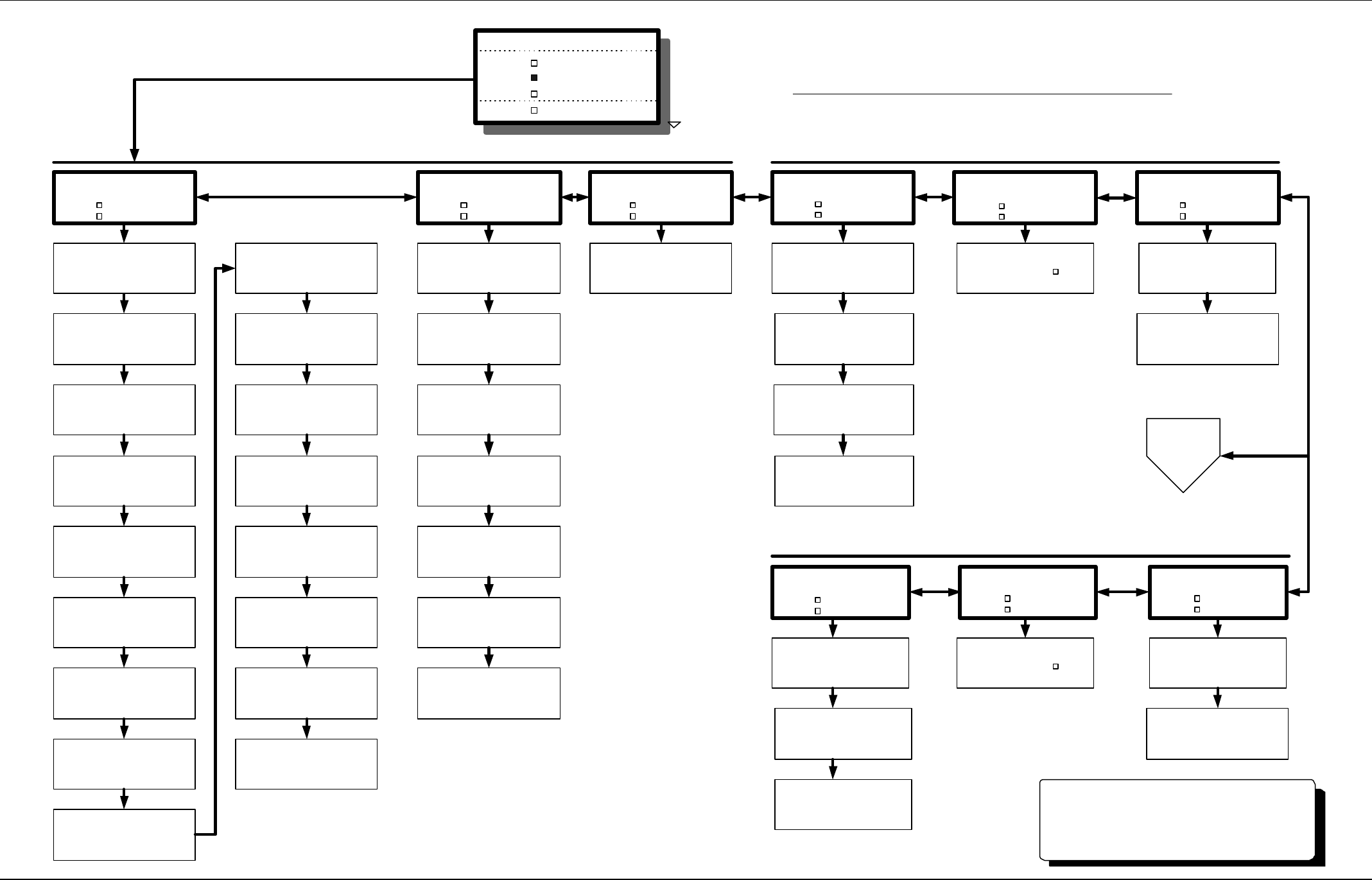
3-8 Front Panel Operation
602-13068-01 Rev A NXE1 Digital Radio
QAM RADIO TX A / B**
QAM RADIO RX
QAM RADIO MODEM A / B**
Figure 3-2b
LCD SCREEN MENU TREE
Figure 3-2b
LCD SCREEN MENU TREE
AFC V
TX
%LO
Xctr %
100
100
3.8
Xmtr
TX
W
Fwd
Rev W0.00
1.00
FORC
PA Cur
TX
C
SYNTH
A
Temp LOCK
45
2.50
Freq
QAM Radio TX Config
MHz948.0000
CONFIGURE
QAM Radio Launch
TXA
TX-A Radiate
QAM Radio TX Control
AUTO
CONTROL
QAM Radio Launch
TXA
Freq
QAM Radio RX Config
MHz948.0000
CONFIGURE
QAM Radio Launch
RXA
RX Atten
QAM Radio RX Control
AUTO
CONTROL
QAM Radio Launch
RXA
STATUS
QAM Radio Launch
RXA
FreqA
QAM Radio RX Status
MHz
948.0000
Rcvr
RX
dBmRSL
Atten
FORC
-80
AUTO
RX
VDCAFC
LO %
SYNTH LOCK
4.4
100
QAM Radio - Launch Screens
METER
QAM RADIO
NXE1 MAIN MENU
SYSTEM
ALARMS/FAULTS
Scroll
STATUS
QAM Radio Launch
MODA CONFIGURE
QAM Radio Launch
MODEM COPY
QAM Radio Launch
MODEM
STATUS
QAM Radio Launch
TXA
SLOSS 0.000E+00
ES 0.000E+00
SES 0.000E+00
UNAS 0.000E+00
QAM Modem -80dBm
BER Post 0.000E+00
#Bits 0.000E+00
#Errors 0.000E+00
QAM Modem -80dBm
BER Pre 0.000E+00
#Bits 0.000E+00
#Errors 0.000E+00
Qmdm MOD
Baud LOCK
IFMOD 4 %
Qmdm DEMOD
Baud LOCK
Fec LOCK
Qmdm
Synth LOCK
AFC 3.7 V
Qmdm
IFOUT 95 %
Mode 64Q
Qmdm MOD
Baud 280.5 k
DRT 1535 k
Enc DVB
Qmdm MOD
Spctr NRML
Fltr 18 %
Intrl 3
Qmdm DEMOD
Baud 280.5 k
DRT 1535 k
Enc DVB
Qmdm DEMOD
Spctr NRML
Fltr 18 %
Intrl 3
Qmdm
Test NORMAL
Qmdm
Intfc TRNK
Tx CLOCK
ClkSrc RECOV
ClkPh NORM
Tx Clk Out
Clk Ph NORM
Rx Out
Data Src NORM
Clk Src RECOV
Clk Ph NORM
Qmdm
Fvers 1.5
Xvers 2.1
QAM Modem Configure
Power-On Default
Mode/Effic 32Q/5
Data Rt 2048 k
Intrlv 3
Spctrm INVRT
Fltr 18
Encode DVB
Test PRBS23
Loopback CLR(OFF)
QAM Interface
Intfc DTE(Trnk)
Tx Clock
Clk Source EXT TXC
Clk Phase NORMAL
Tx Clock Out
Clk Phase NORMAL
Rx Clock
Clk Source EXT TXC
Clk Phase NORMAL
QAM Radio Config.
Copy
From POWER ON
To POWER ON
Select QAM RADIO to open Launch Screens (see text)
QAM Radio TX Status
FreqA 948.0000 MHz
QAM Radio TX Config
LO Side LOW
LO Freq 1020.000MHz
LO Step 25.0 KHz
QAM Radio RX Config
LO Side LOW
LO Freq 1020.000MHz
LO Step 25.0 KHz
**Note:"A" module and "Primary" screens
are the dault.
"B" module and "Secondary"
calibrations are available only when
redundant systems are configured.
DTV Menus
on next page
(Figure 3-2c)
3-9 Front Panel Operation
NXE1 Digital Radio 602-13068-01 Rev A
Factory Calibration
RADIO TX-A CAL
AFC LVL
LO LVL
QAM MODEM-B CAL
RADIO TX CAL
UNIT A
UNIT B
QAM MODEM CAL
UNIT A
UNIT B
FWD PWR-A Calibr
Cal Value
190 27
-9999.00
Pwr Adjust
Reading 1.00
10.00 A
1.72 A
RADIO TX-A CAL
FWD PWR
REV PWR PA CUR
ALC
RADIO TX-B CAL
FWD PWR
REV PWR PA CUR
ALC
RADIO TX-B CAL
AFC LVL
LO LVL
PA Current-A Calib
Cal Value
Reading
ALC-A Calibr
PA ALC AUTO
REV PWR-A Calibr
Cal Value 0.25 W
Reading
XCTR LVL-A Calibr
Cal Value 100 %
100 %
Reading
LO LVL-A Calibr
Cal Value 100 %
52.94 %
Reading
AFC LVL-A Calibr
Calibr Val 4.50
0.85
Reading
SYSTEM CAL
15V-RFA
+15VA
+5VD
BATT
OCXO AFC LVL
MOD LVL
SYNTH LVL
OCXO-A Cal
Mode 194
SLAVE
Freq Adj
Synth Lvl-A Cal
Cal Value 100.0
96.00
Reading
Mod Lvl-A Cal
Cal Value 100.00
95.96
Reading
AFC Lvl-A CAL
Cal Value 4.50
3.67
Reading
OCXO-B Cal
Mode 194
SLAVE
Freq Adj
Synth Lvl-B Cal
Cal Value 100.0
96.00
Reading
Mod Lvl-B Cal
Cal Value 100.00
95.96
Reading
AFC Lvl-B CAL
Cal Value 4.50
3.67
Reading
QAM MODEM-A CAL
Figure 4-2c
SL9003Q SCREEN MENU TREE
Figure 4-2c
SL9003Q SCREEN MENU TREE
OCXO AFC LVL
MOD LVL
SYNTH LVL
Note: "B" Module and "Secondary" calibrations are available only when
redundant systems are configured.
"A" module and "Primary" screens are the default.
METER
QAM RADIO
NXE1 MAIN MENU
SYSTEM
ALARMS/FAULTS
Scroll
Factory Calibrate
RADIO TX
RADIO RX
QAM MODEM
SYSTEM
RADIO RX-A CAL
RSL
AFC LVL
LO LVL
LO LVL-A CAL
Calibr Val 100
Reading 4.05
AFC LVL-A CAL
Calibr Val 4.50Reading 4.05
RSL-A CAL
RADIO RX CAL
UNIT A
UNIT B
RADIO RX-B CAL
RSL
AFC LVL
LO LVL
Calibr Val
-50.00Hi Reading
0.00
LO LVL-B CAL
Calibr Val 100Reading 4.05
AFC LVL-B CAL
Calibr Val 4.50
Reading 4.05
XCTR LVL
-9999.00
2.40
0.00
FWD PWR-B Calibr
Cal Value
190 27
-9999.00
Pwr Adjust
Reading 1.00
10.00 A
1.72 A
PA Current-B Calib
Cal Value
Reading
ALC-B Calibr
PA ALC AUTO
REV PWR-B Calibr
Cal Value 0.25 W
Reading
XCTR LVL-B Calibr
Cal Value 100 %
100 %
Reading
LO LVL-B Calibr
Cal Value 100 %
52.94 %
Reading
AFC LVL-B Calibr
Calibr Val 4.50
0.85
Reading
-9999.00
2.40
0.00
XCTR LVL
cw OFF cw OFF -70.00
Lo Reading
RSL-B CAL
Calibr Val
-50.00
Hi Reading
0.00
-70.00Lo Reading
System Cal
EXTERNAL ANALOG
#1 #2 #3 #4
15V-RFA-Prim. Calib
Reading 15.00
Calibr Val 14.50
Battery-Prim. Calib
Reading 15.00
Calibr Val 14.50
+5VD Calib
Reading 15.00
Calibr Val-9999.00
+15VA Calib
Reading 15.00
Calibr Val 14.50
Extern A/D 1 Calib
Reading 15.00
Calibr Val 12.00
Extern A/D 2 Calib
Reading 15.00
Calibr Val 12.00
Extern A/D 3 Calib
Reading 15.00
Calibr Val 12.00
Extern A/D 4 Calib
Reading 15.00
Calibr Val 12.00
CARD VIEW
POWER SUPPLY
INFO
System
FACTORY CAL
Scroll
BASIC CARD SETUP
DATE/TIME
TRANSFER
EXTERNAL I/O
Figure 3-2d
LCD SCREEN MENU TREE
Front Panel Operation 3-10
602-95555-01 Rev A NXE1-20 Digital Radio
3.4 Screen Menu Summaries
The following tables and text provide a screen view for that topic as well as the functions and
settings of that screen. The order follows the Screen Menu Tree (Figures 3-2a, b, and c) with the
exception of the QAM Radio screens, which are grouped in the STATUS, CONTROL and
CONFIGURE categories.
Outline of Section 3.4 (Screen Menu Summaries)
A summary of each function is also provided.
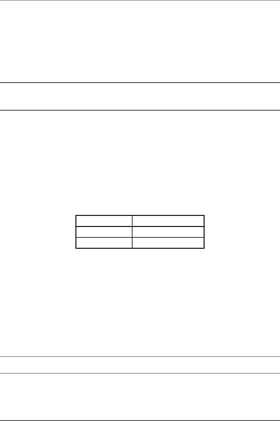
3.4.1 Meter
Meter
DECDR 1 Bargraph
Led Dsp A
Function Settings Summary
Bargraph ENCDR1, 2, etc…
DECDR1, 2, etc…
NONE
Selects the desired audio source for display on the audio
level bargraph
Turns off the bargraph
Led Dsp A
B
The status of Radio A or Radio B is displayed on the
LEDs on the front panel.
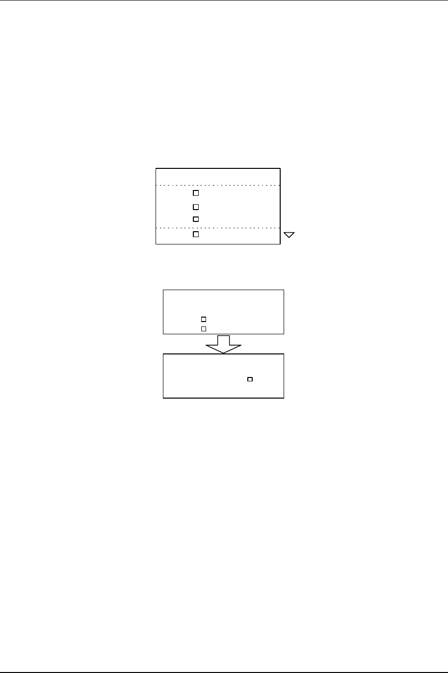
3.4.2 System: Card View
Cards Active B.Addr
QAMOD A
RF TX A 1
1
RF RX A 1
Cards Active B.Addr
MUX 0
CH CD 1 0
0
ENCDR 1 1
Cards Active B.Addr
DECDR 1 1
Function Settings Summary

3-11 Front Panel Operation
NXE1-20 Digital Radio 602-95555-01 Rev A
Cards Active RF RX A
DECDR 1
ENCDR 1
QAMOD A
RF TX A
MUX 0
CH CD 1
QAM Receiver RF Module installed in QAM Radio “A”
slots (base address 0)
Audio Decoder #1 installed (base address 1)
Audio Encoder #1 installed (base address 2)
QAM Modem Module installed in QAM Radio “A” slots
(base address 3)
QAM Transmitter RF Module installed in QAM “A” slots
(base address 4)
Intelligent Multiplexer #0 installed (base address 5)
Note: The card view screen gives the user a list of all installed cards in the unit. The base
address (B. Addr) is listed for diagnostic purposes only.
3.4.3 System: Power Supply
Power Supply Status
Primary
+5VD
+15VD
AC
5.00 V
15.00 V
Function Settings Summary
Primary
AC
DC
Indicates type of supply in primary slot A:
Universal AC input
DC Option
+5 VD 0-9.99 V
5.20 V nominal Voltage level of the main +5 volt supply
+15 VD 0-99.9 V
15.2 V nominal
Voltage level of the main +15 volt supply
3.4.4 System: Info
System Information
Security
Firmware USER
V.2.04
Unit No. 1
Function Settings Summary
Unit No. 1,2,3,… Identification for NMS system
SECURITY
Lockout
User (default)
Factory
Indicates access level of security:
No control available
Limited control of parameters
Full configure and calibration
FIRMWARE V x.xx Revision of front panel screen menu software
Front Panel Operation 3-12
602-95555-01 Rev A NXE1-20 Digital Radio
3.4.5 System: Basic Card Setup
Basic Card Setup
QAM Modem
RF Tx QMA
TXA
Card Id
Card
Audio Enc
RF Rx RXA
ENC1
DEC1
Audio Dec
Id
Card
Chnl Cd
MUX MUX0
CHC1
Id
Function Settings Summary
QAM Modem QMA, QMB QAM Modem installed in QAM Radio slots A or B
RF Tx TXA, TXB QAM Transmitter installed in QAM Radio slots A or B
RF Rx RXA, RXB QAM Receiver installed in QAM Radio slots A or B
Audio Enc ENC1,2,… Audio Encoder installed and identified (affects meter
selection of bargraph)
Audio Dec DEC1,2,… Audio Decoder installed and identified (affects meter
selection of bargraph)
MUX MUX 0,1,… Mux Module installed and identified
Chnl Cd CHC 1,2,… Channel Card installed and identified
Note: These are factory settings of installed cards, used to control appropriate displays in the
CARD VIEW screens.
3-13 Front Panel Operation
NXE1-20 Digital Radio 602-95555-01 Rev A
Note: Pressing enter at each ID type brings up another screen with the Card Function shown
and the question: In System? Is displayed. Depending upon the card type, this screen also
indicates the base address. These windows are shown below:
QAM Modem A
In system? YES
Radio TX A
In system? YES
Radio RX A
In system? YES
Encoder 1
In system? YES
Base addr 1
Decoder 1
In system? YES
Base addr 1
Mux 0
In system? YES
Chnl Base Addr 0
Hooked to Radio NO
Mux 0
Channel Types
1 NONE 3 NONE
2 NONE 4 NONE
Channel Card 1
In system? YES
Base addr 0
Channel Card 1
Channel Types
1 NONE 3 NONE
2 NONE 4 NONE
3.4.6 System: Factory Calibration
Factory Calibrate
RADIO RX
QAM Modem
RADIO TX System
The Factory Calibration Screens are documented in Figure 3-2 (Screen Menu Tree). The user
may refer to this diagram when instructed to do so by customer service technicians.
Front Panel Operation 3-14
602-95555-01 Rev A NXE1-20 Digital Radio
3.4.7 System: Unit-Wide Parameters
Parameter
Main Title
Unit No. 1
NXE1
Value
Redundant ON
IP MSB 207
IP 71
IP 237
IP LSB 115
SNM MSB 255
SNM 255
SNM 255
SNM LSB 0
GW MSB 207
GW 71
GW 237
GW LSB 254
Calc BER always
RMT/LOC LOC
Function Settings Summary
Unit No. 1,2,3,… Identification for NMS system
Main Title TRANSMITTER,
RECEIVER,
TRANSCEIVER
T1
DTV Link
NXE1
Determines main menu display and affects screen menu
selection of modules
Redundant ON
OFF
Hot Standby Dual Radio operation.
Single Radio operation.
IP Integer (0-255) Internet Protocol (IP) address of the device. These
values must be set for the device to possess network
capabilities.
SNM Integer Subnet Mask of the device. Only needs to be set if the
device is to use its network capabilities. Subnetting
allows network administrators additional flexibility in
defining relationships among network hosts.
GW Integer The default Gateway of the device. The Gateway
address is configured by the network administrator. This
address informs each device where to send data if the
target station does not reside on the same subnet as the
source.
Calc BER
always RMT
LOC
(Remote) Use RMT only in SNMP mode.
(Local) Put in local.
3-15 Front Panel Operation
NXE1-20 Digital Radio 602-95555-01 Rev A
3.4.8 System: Date/Time
System Date
Month
Year
Day 29
98
06
System Time
Minute
Second
Hour 15
48
35
Function Settings Summary
Day
Month
Year
01-31
01-12
00-99
Sets the system date used for NMS and Fault/Alarm
logging
After selection, press ENTER to save
Hour
Minute
Second
00-23
00-59
00-59
Sets the system time used for NMS and Fault/Alarm
logging
After selection, press ENTER to save
3.4.9 System: Transfer
Transfer
Tx Transfer OFF
Rx Transfer OFF
Function Settings Summary
TX Transfer OFF
HOT
COLD
Configures the internal logic for transfer panel (TP64) TX
control
RX Transfer OFF
ON Configures the internal logic for transfer panel (TP64) RX
control
Front Panel Operation 3-16
602-95555-01 Rev A NXE1-20 Digital Radio
3.4.10 External I/O
Ext A/D Readings
#1- 0.56
#3- 0.00 #2- 0.00
#4- 0.00
Ext Status Readings
#1 #3
#2 #4
OFF OFF OFF OFF
Ext Relays
RELAY CONTROLS
MAP FAULTS-RELAYS
Control Relays
#1- OFF
#3- OFF #2- ON
#4- ON
Faults
Map to Relays? ON
Ext D/A
Output RX SIG LVL
Function Settings Summary
Ext A/D
Readings #1, #2, #3, #4 Voltage readings via the NMS I/O card
Ext Status
Readings #1, #2, #3, #4 Logic Level readings via the NMS I/O card
Ext Relays #1, #2, #3, #4 Control of relays at the NMS I/O card
Map Faults-
Relays ON
OFF Maps pre-determined fault conditions to trigger relays at
the NMS I/O card
Ext D/A Output RX SIG LVL
NOTHING
TX FWD PWR
External output follows Receive Signal Level.
External output follows nothing.
External output follows Transmit Forward Power.

3-17 Front Panel Operation
NXE1-20 Digital Radio 602-95555-01 Rev A
3.4.11 Alarms
Alarm(s)
Total Alarms Since
Reset-1
Alarm(s)
Rev Pwr > 0.25 W
15:20:24 6/29/98
Module Parameter Nominal Trip Value
QAM RF TX Reverse Power 0.05 Watt > 0.25 Watt
PA Current 2.5 Amp > 3.0 Amp
LO Level 100% < 50%
Exciter Level 100% < 50%
QAM RF RX RSL -30 to –90 dBm
LO Level 100% < 50%
QAM MODEM BER - >1.00E-04
Synth Level 100% < 50%
Modulator only Modem Level 100% < 50%
Alarm definition: A specific parameter is out of tolerance, but is NOT crucial for proper
system operation. ALARMS are cautionary only, and indicates a degradation in a system
parameter.
Logging: All fault and alarm events are logged with the date and time.
Alarm screen reset: After viewing the screen, press ENTER to clear all logs entries. If the
alarm has been corrected, no new logs will be generated.

Front Panel Operation 3-18
602-95555-01 Rev A NXE1-20 Digital Radio
3.4.12 Faults
Fault(s)
Total Faults Since
Reset-1
Fault(s)
Fwd Pwr < 0.5 W
15:18:43 6/29/98
Module Parameter Nominal Trip Value
QAM RF TX Forward Power 1.0 Watt < 0.5 Watt
AFC Lock Lock Unlock
PA Temp 40 deg C >80 deg C
QAM RF RX AFC Lock Lock Unlock
QAM MODEM AFC Lock Lock Unlock
Mbaud Lock Unlock
Dbaud Lock Unlock
Dfec Lock Unlock
Fault definition: A specific parameter is out of tolerance and is crucial for proper system
operation.
Logging: All fault and alarm events are logged with the date and time.
Fault screen reset: After viewing the screen, press ENTER to clear all logs entries. If the
fault has been corrected, no new logs will be generated.
3.4.13 G821 Parameters
QAM Modem
SLOSS 0.000E +00
ES 0.000E +00
SES 0.000E +00
UNAS 0.000E +00
Function Settings Summary
SLOSS 0.000E +00 Number of times the signal has been lost for more than
10 seconds
ES 0.000E +00 Errored seconds
SES 0.000E +00 Severely errored seconds
UNAS 0.000E +00 Unavailable seconds
3-19 Front Panel Operation
NXE1-20 Digital Radio 602-95555-01 Rev A
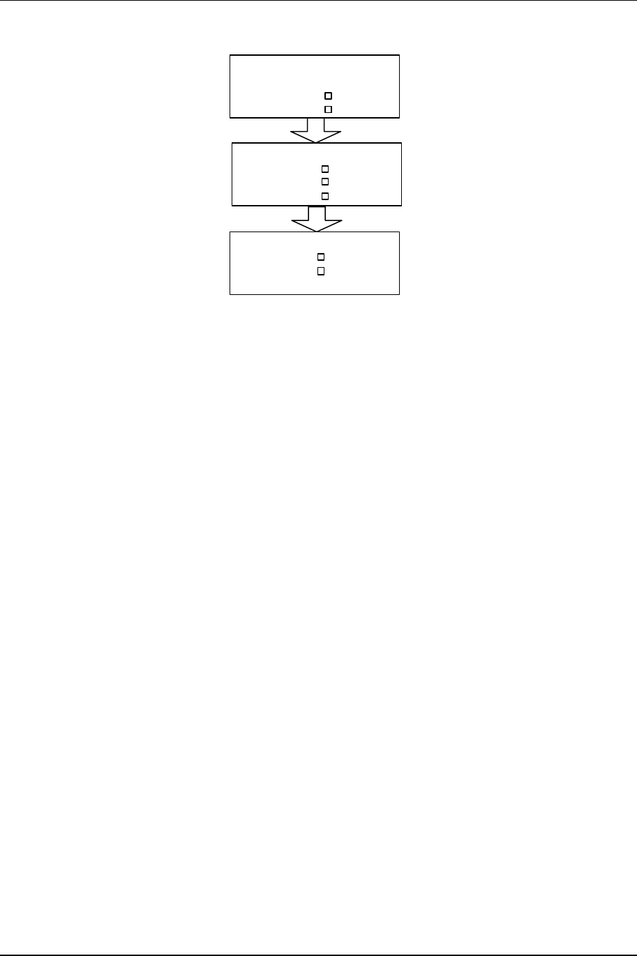
3.4.14 QAM Modem Status
QAM Modem
BER Post
#Bits
#Errors
-80 dBm
0.00E+00
0.0000E+00
0.0000E+00
QAM Modem
BER Pre
QAM Modem
#Bits
#Errors
-80 dBm
0.00E+00
0.0000E+00
0.0000E+00
Function Settings Summary
BER Post 0.00E-00 Post-FEC (Forward Error Correction) Bit Error Rate since
last “ENTER” reset
BER Pre 0.00E-00 Pre-FEC (Forward Error Correction) Bit Error Rate since
last “ENTER” reset
# Bits 0.0000E+00 # of Bits counted since last “ENTER” reset
# Errors 0.0000E+00 # of Errors counted since last “ENTER” reset
Note:
Received Signal Level
Front Panel Operation 3-20
602-95555-01 Rev A NXE1-20 Digital Radio
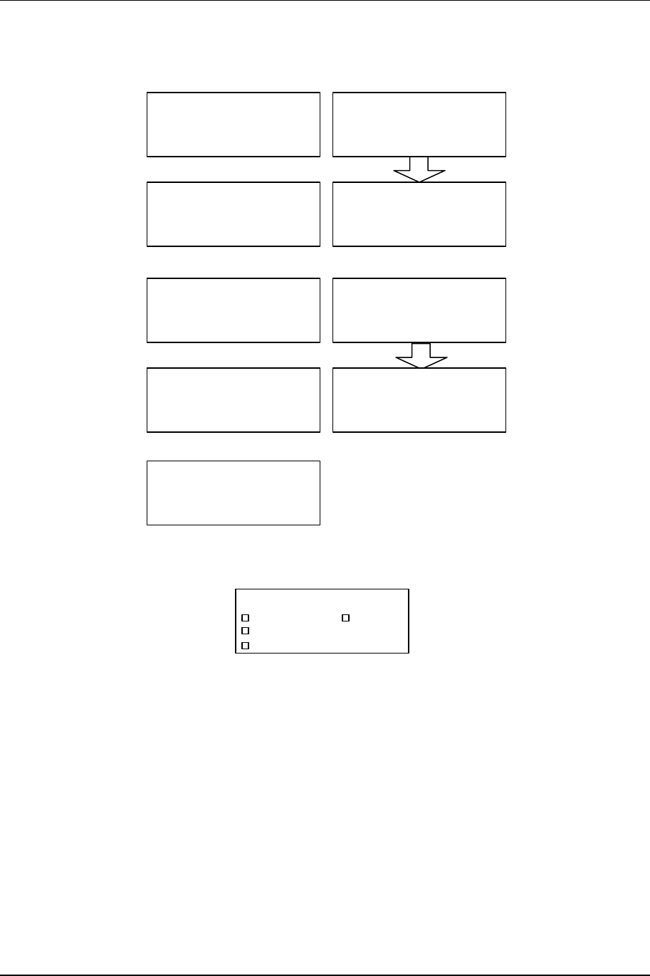
QAM Modem Status (continued)
Qmdm
Synth LOCK
AFC 3.7 V
Baud
Qmdm DEMOD
Fec LOCK
LOCK
Baud
Qmdm MOD
IFMOD LOCK
4 %
Qmdm MOD
Fltr
Intrl
Spctr %
NRML
18
3
Qmdm
Mode %
IFOUT 95
64Q
Qmdm MOD
DRT
Enc
k
Baud k
280.5
1535
DVB
Function Settings Summary
BAUD LOCK (default)
UNLOCK
Indicates modulator PLL is locked to incoming data
clock
IFMOD 0 – 100%
100% NOM
BAUD LOCK (default)
UNLOCK Indicates demodulator PLL is locked to incoming
data clock
FEC LOCK (default)
UNLOCK
Indicates FEC decoder is synchronized
SYNTH LOCK (default)
UNLOCK
Confirms 70 MHz IF synthesizer is phase locked
AFC 0 – 9.9 VDC
3.7 VDC (nominal) 70 MHz IF synthesizer AFC voltage
IFOUT 0 – 100%
100% (nominal)
Modulator level
Mode 16-64Q Modulation mode:16QAM, 32QAM, 64QAM
BAUD 280.5 K Symbol rate
DRT 1535 K Data rate
ENC DVB Encoding mode
SPCTR NRML Spectrum Normal or Invert
FLTR 18 % Nyquist filter
INTRL 3 Interleave Depth
Continued on next page.
3-21 Front Panel Operation
NXE1-20 Digital Radio 602-95555-01 Rev A
QAM Modem Status (continued)
Qmdm DEMOD
DRT
Enc
kBaud k
280.5
1535
DVB
Qmdm DEMOD
Fltr
Intrl
Spctr %
NRML
18
3
Qmdm
Test NORMAL
Qmdm Intfc
Intfc TRNK
TX CLOCK
Clk Src Recov
Clk Ph Norm
TX CLK OUT
Clk Ph Norm
RX OUT
Data Src Norm
Clk Src Recov
Clk Ph Norm
Qmdm
FVers 1.5
XVers 2.1
Function Settings Summary
BAUD 280.5 K Symbol rate
DRT0 1535 K Data rate
ENC DVB Encoding mode
SPCTR NRML Spectrum Normal or Invert
FLTR 18 % Nyquist filter
INTRL 3 Interleave Depth
TEST NORMAL Internal Test Pattern Generator
Interface Trunk Active Interface
Clk Src (Tx
Clock)
Internal, EXT TXC,
EXT RXC,
Recovered
Clock source of the Transmitter.
Clk Ph (Tx
Clock)
Inverted, Normal Clock Phase of the Transmitter.
Clk Ph (Tx
Clock Out)
Inverted, Normal Clock Phase of the Transmitter Clock Out.
Data Src (Rx
Out)
Norm, RPT, Loop Data Source of the Receiver Out. Normal means the
source is either BKPLN or TRNK; RPT sets the radio to
Repeater; Loop sets the radio to loopback mode.
Clk Src (Rx
Out)
Internal, EXT TXC,
EXT RXC, Recov Clock Source of the Receiver Out.
Clk Ph (Rx
Out)
Norm, Inverted Clock Phase of the Receiver Out.
Fvers
Xvers
Internal is the internal clock of the NXE1; EXT TXC is the External Transmit Clock; EXT RXC is
the External Receive Clock; Recovered is the recovered clock from the receiving RF.
Front Panel Operation 3-22
602-95555-01 Rev A NXE1-20 Digital Radio
3.4.15 QAM Radio TX Status
AFC V
Tx
%
LO
Xctr %100
100
3.8
Xmtr
TX
W
Fwd
Rev W0.00
1.00
FORC
PA Cur
Tx
C
Synth
A
Temp
LOCK
45
2.50
Freq
QAM Radio TX Status
MHz
AFC V
Tx
%LO
Xctr %100
100
3.8
Xmtr
TX
FORC
Tx
Synth LOCK
Freq
QAM Radio TX Status
MHzxxxx.xxx
DTV Menus
xxxx.xxx
Function Settings Summary
Freq A 2300.00MHz Displays the transmitter output carrier frequency
XMTR
TRAFFIC
FORCED (default)
Status of transmitter:
ON in a hot standby mode
Forced ON
FWD 0 – 9.99 Watt
1.00 Watt (nominal)
Output Power of TX. This menu item does not appear
when the unit is configured for DTV.
REV 0 – 9.99 Watt
0.07 Watt (nominal)
Reverse (or reflected) power at antenna port. This
menu item does not appear when the unit is
configured for DTV.
PA CUR 0.00– 9.99 Amp
2.40 Amp (nominal) Power amplifier current consumption. This menu item
does not appear when the unit is configured for DTV.
TEMP 0– 99.9 deg C
45.0 deg C (nominal)
Power amplifier temperature. This menu item does not
appear when the unit is configured for DTV.
SYNTH LOCK (default)
UNLOCK
Indicates phase lock of the 1st LO
AFC 0 – 9.9 VDC
3.8 VDC (nominal) 1st LO PLL AFC Voltage
LO 0 – 99.9%
100% (nominal)
1st LO relative power level
XCTR 0 – 99.9%
100% (nominal)
Transmit module’s relative output power level
3-23 Front Panel Operation
NXE1-20 Digital Radio 602-95555-01 Rev A
3.4.16 QAM Radio RX Status
Freq
QAM Radio RX Status
MHzxxxx.xx
Rcvr
RX
dBmRSL
Atten
FORC
-80
AUTO
RX
V
AFC
LO %
SYNTH LOCK
4.4
100.0
Function Settings Summary
Freq A 2300.00 MHz Displays the receiver operating frequency
XMTR
TRAFFIC
FORCED (default)
Transfer status of receiver:
Is operating, ready for transfer
Is operating, will not transfer (forced ON)
RSL -30.0 to -90.0 dBm Received signal level (signal strength)
Nominal level dependent upon customer path/system
gain
ATTEN
AUTO (default)
ON
OFF
Receiver PIN attenuator setting:
Controlled by internal software
Forced ON
Forced Off
SYNTH LOCK (default)
UNLOCK Indicates phase lock of the 1st LO
AFC 0 – 9.9 VDC
3.5 VDC (nominal)
1st LO PLL AFC Voltage
LO 0 – 99.9%
100% (nominal)
1st LO relative power level
3.4.17 QAM Radio TX Control
TX Radiate
QAM Radio TX Control
AUTO
Function Settings Summary
TX-A Radiate AUTO (default)
ON
OFF
Transmitter radiating, but folds back output power on
high antenna VSWR (REV PWR)
Transmitter radiating
Transmitter not radiating

Front Panel Operation 3-24
602-95555-01 Rev A NXE1-20 Digital Radio
3.4.18 QAM Radio RX Control
RX Atten
QAM Radio RX Control
AUTO
Function Settings Summary
RX-A ATTEN AUTO (default)
ON
OFF
ON, and is activated on high signal level
ON always
OFF
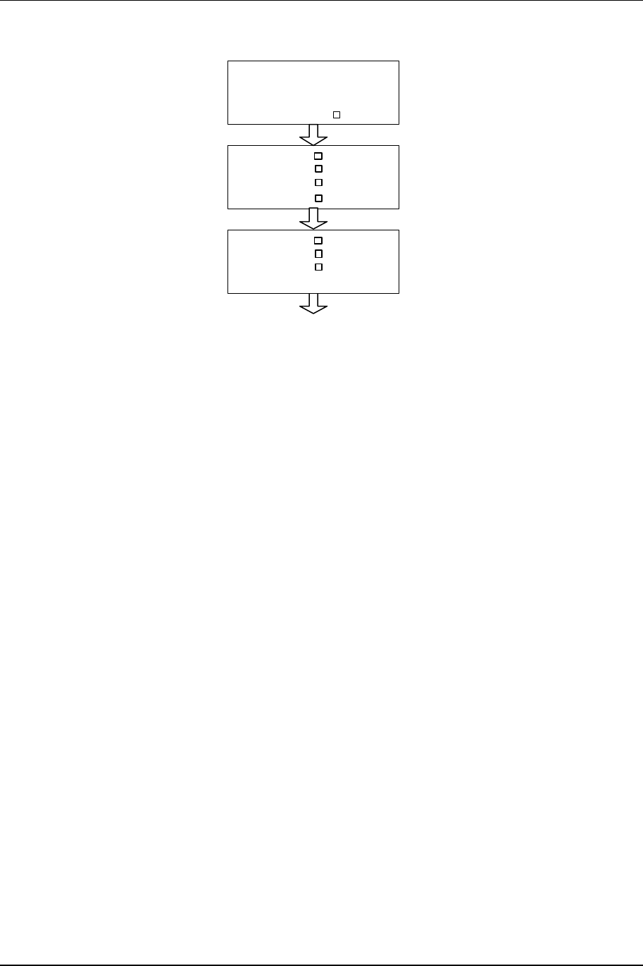
3-25 Front Panel Operation
NXE1-20 Digital Radio 602-95555-01 Rev A
3.4.19 QAM Modem Configure
Power-On Default
QAM Modem Configure
Mode/Effic 32Q/5
Spctrm
Fltr 18
INVRT
Intrlv
Data Rt 3
2048 k
Test
Encode PRBS23
DVB
Loopback CLR(OFF)
Function Settings Summary
Interface QPSK/2, 16Q/4, 32Q/5, 64Q/6,
128Q/7, 256Q/8 Default is 64QAM
DATA RATE N x 64 kbps, Valid range depends upon configuration.
INTERLEAVE 1
2
3 (default)
4
6
12
2,17
2,34
2,51
2,68
2,102
2,204
Interleave depth.
1 to 204
SPECTRUM INVERT (default)
FILTER 18
15 (default)
12
Nyquist roll-off factor
ENCODING DVB (default) Raw data format
TEST NORMAL (default)
PRBS15, PRBS23
Test pattern length
Loopback CLR (Off)
RMT+LOC
RPTR
Loopback mode
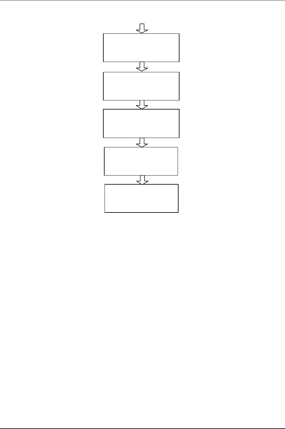
Front Panel Operation 3-26
602-95555-01 Rev A NXE1-20 Digital Radio
QAM Modem Configure (continued)
QAM Interface
Intfc DTE Trnk
TX CLOCK
Clk Src Recov
Clk Ph Norm
TX Clk Out
Clk Ph Norm
RX Out
Data Src Norm
Clk Src Norm
Clk Ph Norm
Qmdm
FVERS 1.5
XVER 2.1
Function Settings Summarys
Interface Trunk
Radio (bkpln)
Uses Trunk for I/O.
Uses Backplane for I/O.
Clk Src (Tx
Clock)
Internal, EXT TXC,
EXT RXC,
Recovered
Clock source of the Transmitter.
Clk Ph (Tx
Clock)
Inverted, Normal Clock Phase of the Transmitter.
Clk Ph (Tx
Clock Out)
Inverted, Normal Clock Phase of the Transmitter Clock Out.
Data Src (Rx
Out)
Norm, RPT, Loop Data Source of the Receiver Out. Normal means the
source is either BKPLN or TRNK; RPT sets the radio to
Repeater; Loop sets the radio to loopback mode.
Clk Src (Rx
Out)
Internal, EXT TXC,
EXT RXC, Recov Clock Source of the Receiver Out.
Clk Ph (Rx Out) Norm, Inverted Clock Phase of the Receiver Out.
Fvers
Xvers
Internal is the internal clock of the NXE1-20; EXT TXC is the External Transmit Clock; EXT
RXC is the External Receive Clock; Recovered is the recovered clock from the receiving RF.
NOTE: See the User Clock Options Conceptual Diagram in Figure 3-4 below for clarification.
3.4.19.1 Typical Configuration
A typical installation of NXE1-20 Digital Radios involves configuring each NXE1-20 as either Data
Communications Equipment (DCE) or as Data Terminal Equipment (DCE), as illustrated below:
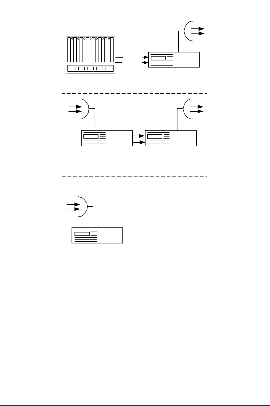
3-27 Front Panel Operation
NXE1-20 Digital Radio 602-95555-01 Rev A
Telecom Equipment Configured
as DTE
Rx Clock
Tx Clock
Configured
as DCE
Configured
as DTE
Repeater
(DCE coupled with a DTE)
Configured
as DCE
A DCE coupled together with a DTE enables the signal to be relayed to another DCE. This
configuration is called a Repeater. A network can consist of as many Repeaters as necessary.
The following sub-sections describe how to configure the NXE1-20 a DCE or as a DTE.
3.4.19.2 NXE1-20 as Data Communications Equipment (DCE)
By default, the NXE1-20 is configured as Data Communications Equipment (DCE). In the mode,
the device recovers the transmitted clocks and effectively performs as a modem.
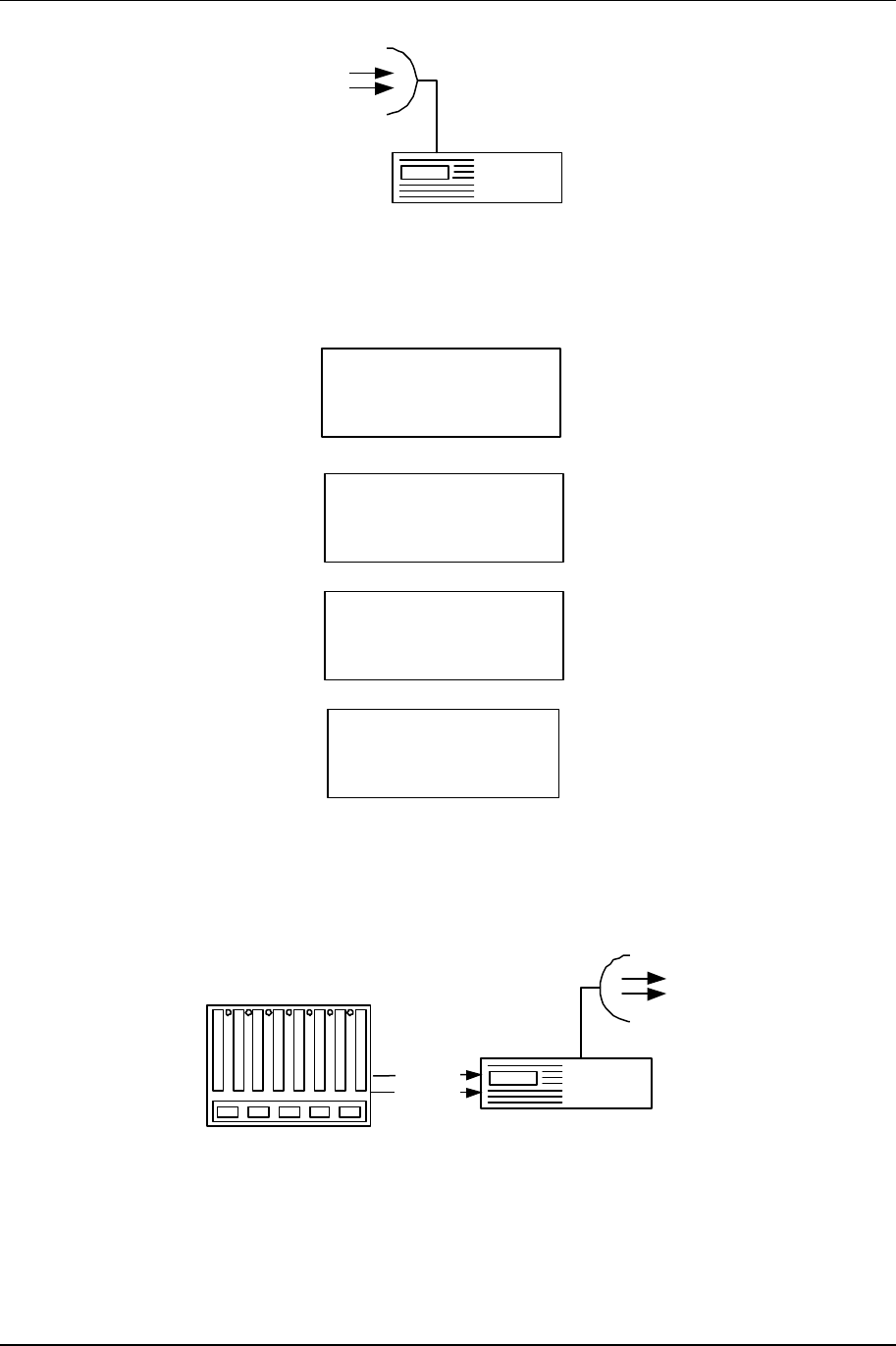
Front Panel Operation 3-28
602-95555-01 Rev A NXE1-20 Digital Radio
Configured
as DCE
To configure the NXE1-20 as a DCE, select the following clock settings in the System menu:
TX CLOCK
Clk Src Recov
Clk Ph Norm
TX CLK OUT
Clk Ph Norm
RX CLOCK
Clk Src Recov
Clk Ph Norm
QAM Inerface
Intfc DCE Trunk
3.4.19.3 NXE1-20 as Data Terminal Equipment (DTE)
When configured as Data Terminal Equipment (DTE), the NXE1-20 gets its clock from an
external source, such as a telecommunications device.
Telecom Equipment Configured
as DTE
Rx Clock
Tx Clock

3-29 Front Panel Operation
NXE1-20 Digital Radio 602-95555-01 Rev A
To configure the NXE1-20 as a DTE, make the following clock selections in the System menu:
TX CLOCK
Clk Src EXT TXC
Clk Ph Norm
TX CLK OUT
Clk Ph Norm
RX CLOCK
Clk Src EXT TXC
Clk Ph Norm
QAM Interface
Intfc DTE Trunk
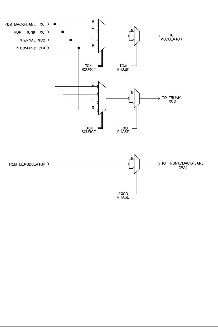
Front Panel Operation 3-30
602-95555-01 Rev A NXE1-20 Digital Radio
3.4.19.4 User Clock Options Conceptual Diagram
Figure 3-4. User Clock Options Conceptual Diagram
3-31 Front Panel Operation
NXE1-20 Digital Radio 602-95555-01 Rev A
3.4.20 QAM Radio TX Configure
Freq
QAM Radio TX Config
MHzxxxx.xx
LO Side
QAM Radio TX Config
LOW
LO Freq MHz1020.0000
LO Step KHz25.0
press
'ENTER'
press
'ESC'
Save Setting ? No
press "Left
arrow" to say
YES
press
'ENTER'
Function Settings Summary
FREQ 2300.00 MHz
Displays the frequency of the transmitter and allows the
user to make frequency changes.
LO Side LOW
HIGH
LOW: LO freq is less than carrier freq.
High: LO freq is greater than carrier freq.
LO Freq 2370 MHz
LO Step 25.0 KHz Programming frequency step size
Front Panel Operation 3-32
602-95555-01 Rev A NXE1-20 Digital Radio
3.4.21 QAM Radio RX Configure
Freq
QAM Radio RX Config
MHzxxxx.xx
LO Side
QAM Radio RX Config
LOW
LO Freq MHz
1020.0000
LO Step KHz25.0
press
'ENTER'
press
'ESC'
Save Setting ? No
press "Left
arrow" to say
YES
press
'ENTER'
Function Settings Summary
FREQ 2300.00MHz
Displays the frequency of the receiver and allows the
user to make frequency changes.
LO Side LOW
HIGH
LOW: LO freq is less than carrier freq.
High: LO freq is greater than carrier freq.
LO Freq 2370.00 MHz
LO Step 25.0 KHz Programming frequency step size
3.5 NMS/CPU PC Configuration Software
The NMS/CPU card is configured with a Windows-based PC software package. The hardware is
accessed through the serial port on the NMS card back panel. See the manual for Moseley
NXE1-20 Configuration Software for more information.
3.6 Up/Down Converter: Frequency Adjust
3.6.1 TX Frequency Adjust
It is possible to change the carrier frequency of the transmitter via the front panel.
Before changing frequency ensure that this is carried out in a controlled environment with test
equipment to ensure that you are transmitting the defined frequency:
1. Power-up the unit and navigate the LCD screens as follows:
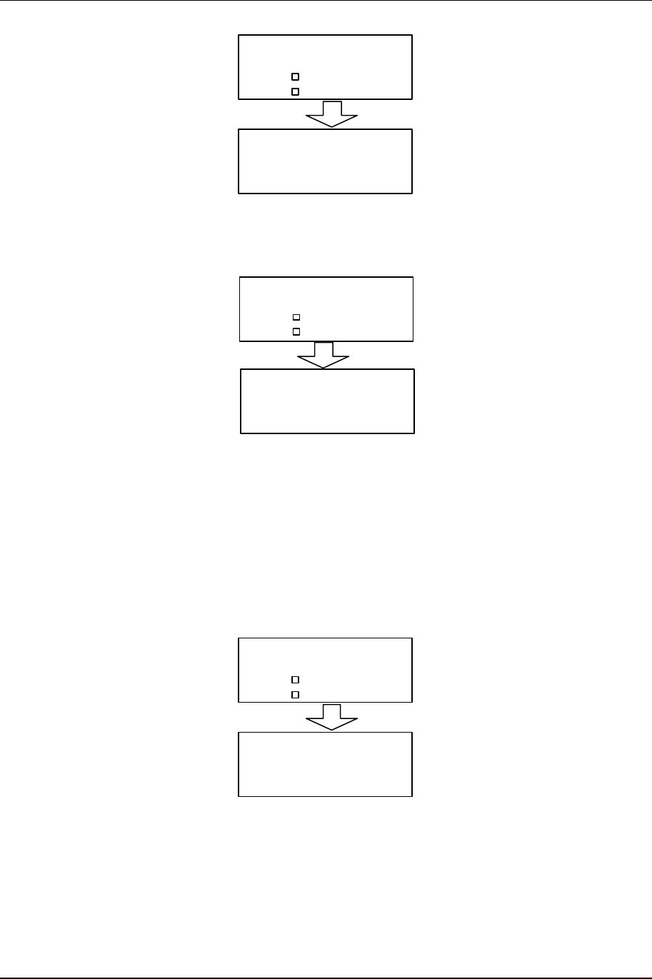
3-33 Front Panel Operation
NXE1-20 Digital Radio 602-95555-01 Rev A
CONFIGURE
QAM Radio Launch
TXA
Freq
QAM Radio TX Config
MHzxxxx.xx
1. Using the cursors, change to the desired frequency. Press ENTER and the TX will
most likely lose AFC LOCK.
2. Navigate the LCD screens to monitor the AFC voltage as follows
STATUS
QAM Radio Launch
TXA
AFC VDC
TX
%LO
Xctr %50
50
4.5
1. Ensure that the voltage reads 0.5 to 9.5 +/- .25 VDC.
2. The TX should achieve AFC LOCK and the operation is successful.
3.6.2 AFC Level—RX
It is possible to change the operating frequency of the receiver via the front panel.
Before changing frequency ensure that this is carried out in a controlled environment with test
equipment to ensure that you are transmitting the defined frequency:
1. Power-up the unit and navigate the LCD screens as follows:
CONFIGURE
QAM Radio Launch
RXA
Freq
QAM RADIO RX Config
MHzxxxx.xx
1. Using the cursors, change to the desired frequency. Press ENTER and the RX will
most likely lose AFC LOCK.
2. Navigate the LCD screens to monitor the AFC voltage as follows

Front Panel Operation 3-34
602-95555-01 Rev A NXE1-20 Digital Radio
STATUS
QAM Radio Launch
RXA
RX
VDCAFC
LO %
SYNTH LOCK
4.5
100
3. Ensure that the voltage reads 0.5 to 9.5 +/- .25 VDC.
4. The RX should achieve AFC LOCK and the operation is successful.
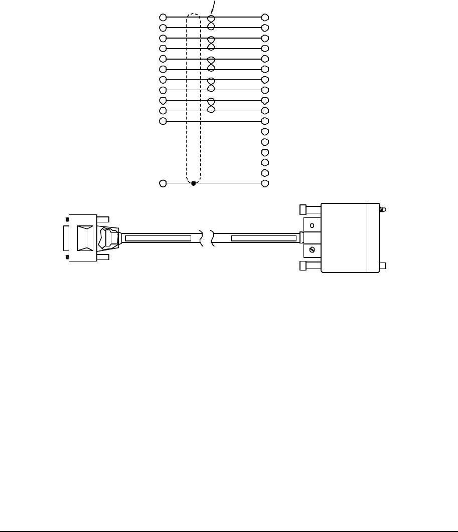
NXE1-20 Digital Radio 602-95555-01 Rev A
4 Data Interface Cables
6
7
13
14
4
5
T
S
P
W
U
R
TXD_I_A
TXD_I_B
RXD_O_A
RXD_O_B
TXC_I_A
TXC_I_B
SEND DATA (A)
SEND DATA (B)
RECEIVE DATA (A)
TERMINAL TIMING (B)
TERMINAL TIMING (A)
RECEIVE DATA (B)
RXC_O_B
RXC_O_A
TXC_O_B
TXC_O_A
10
1
11
2
3
RECEIVE TIMING (A)
RECEIVE TIMING (B)
SIGNAL GROUND
SEND TIMING (B)
SEND TIMING (A)
V
B
X
Y
AA
CHASSIS GROUND
A
MUX CHANNEL
HD15M
V.35 FEMALE
TWISTED
PAIR
INDICATES
(DCE)
CONN SHELL GND
SIG_GND
DATA SET READY
DATA TERMINAL READY
E
F
H
C
D
RECEIVE LINE SIGNAL DETECTOR
CLEAR TO SEND
REQUEST TO SEND
SHIELD
Figure 4-10. Mux Channel – V.35 (DCE)
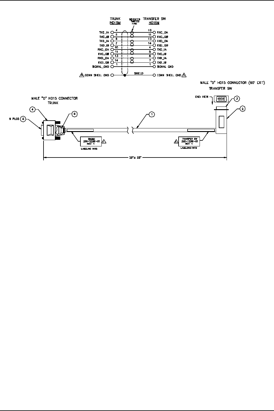
Appendix 4-2
602-95555-01 Rev A NXE1-20 Digital Radio
Figure 4-12. Trunk to Trunk Cable (Mux-Trunk Null)

5-3 Appendix
NXE1-20 Digital Radio 602-95555-01 Rev A
5 Appendix
5.1 Path Evaluation Information
5.1.1 Introduction
5.1.1.1 Line of Site
For the proposed installation sites, one of the most important immediate tasks is to determine
whether line-of-site is available. The easiest way to determine line-of-site is simply to visit one of
the proposed antenna locations and look to see that the path to the opposite location is clear of
obstructions. For short distances, this may be done easily with the naked eye, while sighting over
longer distances may require the use of binoculars. If locating the opposing site is difficult, you
may want to try using a mirror, strobe light, flag, weather balloon or compass (with prior
knowledge of site coordinates).
5.1.1.2 Refraction
Because the path of a radio beam is often referred to as line-of-site, it is often thought of as a
straight line in space from transmitting to receiving antenna. The fact that it is neither a line, nor
is the path straight, leads to the rather involved explanations of its behavior.
A radio beam and a beam of light are similar in that both consist of electromagnetic energy; the
difference in their behavior is principally due to the difference in frequency. A basic characteristic
of electromagnetic energy is that it travels in a direction perpendicular to the plane of constant
phase; i.e., if the beam were instantaneously cut at right angle to the direction of travel, a plane of
uniform phase would be obtained. If, on the other hand, the beam entered a medium of non-
uniform density and the lower portion of the beam traveled through the denser portion of the
medium, its velocity would be less than that of the upper portion of the beam. The plane of
uniform phase would then change, and the beam would bend downward. This is refraction, just
as a light beam is refracted when it moves through a prism.
The atmosphere surrounding the earth has the non-uniform characteristics of temperature,
pressure, and relative humidity, which are the parameters that determine the dielectric constant,
and therefore the velocity of radio wave propagation. The earth’s atmosphere is therefore the
refracting medium that tends to make the radio horizon appear closer or farther away.
5.1.1.3 Fresnel Zones
The effect of obstacles, both in and near the path, and the terrain, has a bearing on the
propagation of radio energy from one point to another. The nature of these effects depends upon
many things, including the position, shape, and height of obstacles, nature of the terrain, and
whether the effects of concern are primary or secondary effects.
Primary effects, caused by an obstacle that blocks the direct path, depend on whether it is totally
or partially blocking, whether the blocking is in the vertical or the horizontal plane, and the shape
and nature of the obstacle.

Appendix 5-4
602-95555-01 Rev A NXE1-20 Digital Radio
The most serious of the secondary effect is reflection from surfaces in or near the path, such as
the ground or structures. For shallow angle microwave reflections, there will be a 180° (half
wavelength) phase shift at the reflection point. Additionally, reflected energy travels farther and
arrives later, directly increasing the phase delay. The difference in distance traveled by the direct
waves and the reflected waves, expressed in wavelengths of the carrier frequency, is added to
the half wavelength delay caused by reflection. Upon arrival at the receiving antenna, the
reflected signal is likely to be out of phase with the direct signal, and may tend to add to or cancel
the direct signal. The extent of direct signal cancellation (or augmentation) by a reflected signal
depends on the relative powers of the direct and the reflected signals, and on the phase angle
between them.
Maximum augmentation will occur when the signals are exactly in phase. This will be the case
when the total phase delay is equal to one wavelength (or equal to any integer multiple of the
carrier wavelength); this will also be the case when the distance traveled by the reflected signal is
longer than the direct path by an odd number multiple of one-half wavelength. Maximum
cancellation will occur when the signals are exactly out of phase, or when the phase delay is an
odd multiple of one-half wavelength, which will occur when the reflected waves travel an integer
multiple of the carrier wavelength farther than the direct waves. Note that the first cancellation
maximum on a shallow angle reflective path will occur when the phase delay is one and one-half
wavelengths, caused by a path one wavelength longer than the direct path.
The direct radio path, in the simplest case, follows a geometrically straight line from transmitting
antenna to receiving antenna. However, geometry shows that there exist an infinite number of
points from which a reflected ray reaching the receiving antenna will be out of phase with the
direct rays by exactly one wavelength. In ideal conditions, these points form an ellipsoid of
revolution, with the transmitting and receiving antennas at the foci. This ellipsoid is defined as the
first Fresnel zone. Any waves reflected from a surface that coincides with a point on the first
Fresnel zone, and received by the receiving antenna, will be exactly in phase with the direct rays.
This zone should not be violated by intruding obstructions, except by specific design amounts.
The first Fresnel zone, or more accurately the first Fresnel zone radius, is defined as the
perpendicular distance from the direct ray line to the ellipsoidal surface at a given point along the
microwave path. It is calculated as follows:
F1 = 2280 × [(d1×d2) / (f × (d1+d2))]½ feet
Where,
d1 and d2 = distances in statute miles from a given point on a microwave
path to the ends of the path (or path segment).
f = frequency in MHz.
F1 = first Fresnel zone radius in feet.
There are in addition, of course, the second, third, fourth, etc. Fresnel zones, and these may be
easily computed, at the same point along the microwave path, by multiplying the first Fresnel
zone radius by the square root of the desired Fresnel zone number. All odd numbered Fresnel
zones are additive, and all even numbered Fresnel zones are canceling.

5-5 Appendix
NXE1-20 Digital Radio 602-95555-01 Rev A
5.1.1.4 K Factors
The matter of establishing antenna elevations to provide minimum fading would be relatively
simple was it not for atmospheric effects. The antennas could easily be placed at elevations
somewhere between free space loss and first Fresnel zone clearance over the predominant
surface or obstruction, reflective or not, and the transmission would be expected to remain stable.
Unfortunately, the effective terrain clearance changes, due to changes in the air dielectric with
consequent changes in refractive bending.
As described earlier, the radio beam is almost never a precisely straight line. Under a given set of
meteorological conditions, the microwave ray may be represented conveniently by a straight line
instead of a curved line if the ray is drawn on a fictitious earth representation of radius K times
that of earth's actual radius. The K factor in propagation is thus the ratio of effective earth radius
to actual earth radius. The K factor depends on the rate of change of refractive index with height
and is given as:
K = 157/157+dN/dh
Where,
N is the radio refractivity of air.
dN/dh is the gradient of N per kilometer.
The radio refractivity of air for frequencies up to 30 GHz is given as:
N = (77.6P/T) + (3.73 x 10⁵ )(e/T2)
Where,
P = total atmospheric pressure in millibars.
T = absolute temperature in degrees Kelvin.
e = partial pressure of water vapor in millibars.
The P/T term is frequently referred to as the "dry" term and the e/T2 term
as the "wet" term.
K factors of 1 are equivalent to no ray bending, while K factors above 1 are equivalent to ray
bending away from the earth's surface and K factors below 1 (earth bulging) are equivalent to ray
bending towards the earth's surface. The amount of earth bulge at a given point along the path
is given by:

Appendix 5-6
602-95555-01 Rev A NXE1-20 Digital Radio
h = (2d1xd2)/3K
Where,
h = earth bulge in feet from the flat-earth reference.
d1 = distance in miles (statute) from a given end of the microwave path to
an arbitrary point along the path.
d2 = distance in miles (statute) from the opposite end of the microwave
path to the same arbitrary point along the path.
K = K-factor considered.
Three K values are of particular interest in this connection:
1. Minimum value to be expected over the path. This determines the degree of "earth
bulging" and directly affects the requirements for antenna height. It also establishes
the lower end of the clearance range over which reflective path analysis must be
made, in the case of paths where reflections are expected.
2. Maximum value to be expected over the path. This leads to greater than normal
clearance and is of significance primarily on reflective paths, where it establishes the
upper end of the clearance range over which reflective analysis must be made.
3. Median or "normal" value to be expected over the path. Clearance under this
condition should be at least sufficient to give free space propagation on non-reflective
paths. Additionally, on paths with significant reflections, the clearance under normal
conditions should not fall at or near an even Fresnel zone.
For most applications the following criteria are considered acceptable:
K = 1.33 and CF = 1.0 F1
K = 1.0 and CF = 0.6 F1
K = 0.67 and CF = 0.3 F1
Where CF is the Fresnel zone clearance and F1 is the first Fresnel zone radius.
5.1.1.5 Path Profiles
Using ground elevation information obtained from the topographical map, a path profile should be
prepared using either true earth or 4/3 earth's radius graph paper. To obtain a clear path, all
obstacles in the path of the rays must be cleared by a distance of 0.6 of the first Fresnel zone
radius. Be sure to include recently erected structures, such as buildings, towers, water tanks,
and so forth, that may not appear on the map. Draw a straight line on the path profile clearing
any obstacle in the path by the distance determined above. This line will then indicate the
required antenna and/or tower height necessary at each end. If it is impossible to provide the
necessary clearance for a clear path, a minimum clearance of 30 feet should be provided. Any
path with less than 0.6 first Fresnel zone clearance, but more than 30 feet can generally be
considered a grazing path.

5-7 Appendix
NXE1-20 Digital Radio 602-95555-01 Rev A
5.1.2 Path Analysis
5.1.2.1 Overview
Path analysis is the means of determining the system performance as a function of the desired
path length, required equipment configuration, prevailing terrain, climate, and characteristics of
the area under consideration. The path analysis takes into account these parameters and yields
the net system performance, referred to as path availability (or path reliability). Performing a
path analysis allows you to specify the antenna sizes required to achieve the required path
availability.
A path analysis is often the first thing done in a feasibility study. The general evaluation can be
performed before expending resources on a more detailed investigation.
The first order of business for performing a path analysis is to complete a balance sheet of gains
and losses of the radio signal as it travels from the transmitter to the receiver. "Gain" refers to an
increase in output signal power relative to input signal power, while "loss" refers to signal
attenuation, or a reduction in power level ("loss" does not refer to total interruption of the signal).
Both gains and losses are measured in decibels (dB and dBm), the standard unit of signal
power.
The purpose of completing the balance sheet is to determine the power level of the received
signal as it enters the receiver electronics—in the absence of multipath and rain fading; this is
referred to as the unfaded received signal level. Once this is known, the fade margin of the
system can be determined. The fade margin is the difference between the unfaded received
signal level and the receiver sensitivity (the minimum signal level required for proper receiver
operation).
The fade margin is the measure of how much signal attenuation due to multipath and rain fading
can be accommodated by the radio system while still achieving a minimum level of performance.
In other words, the fade margin is the safety margin against loss of transmission, or transmission
outage.
5.1.2.2 Losses
Although the atmosphere and terrain over which a radio beam travels have a modifying effect on
the loss in a radio path, there is, for a given frequency and distance, a characteristic loss. This
loss increases with both distance and frequency. It is known as the free space loss and is given
by:
A = 96.6 + 20log10F + 20log10D
Where,
A = free space attenuation between isotropics in dB.
F = frequency in GHz.
D = path distance in miles.
5.1.2.3 Path Balance Sheet/System Calculations
A typical form for recording the gains and losses for a microwave path is shown in Section 5.2.7.
Recall that the purpose of this tabulation is to determine the fade margin of the proposed radio
system. The magnitude of the fade margin is used in subsequent calculations of path availability
(up time).

Appendix 5-8
602-95555-01 Rev A NXE1-20 Digital Radio
The following instructions will aid you in completing the Path Calculation Balance Sheet (see
Section 5.2.7):
Instructions
A. Line 1. Enter the power output of the transmitter in dBm. Examples: 5w = +37.0 dBm,
6.5w = +38.0 dBm, 7w = +38.5 dBm, 8w = +39.0 dBm (dBm = 30 + 10 Log Po [in watts]).
B. Lines 2 & 3. Enter Transmitter and Receiver antenna gains over an isotropic source.
Refer to the Antenna Gain table below for the power gain of the antenna. Note: If the
manufacturer quotes a gain in dBd (referred to a dipole), dBi is approximately dBd +1.1
dB.
C. Line 4. Total lines 1, 2, and 3, and enter here. This is the total gain in the proposed
system.
D. Line 5. Enter amount of free space path loss as determined by the formula given in
Section 5.2.2.
E. Line 6. Enter the total transmitter transmission line loss. Typical losses can be found in
Table 5-3.
Table 5-3
Transmission Line Loss
FREQUENCY
BAND LDF4-50
(per 100 meters) LDF5-50
(per 100 meters)
450 MHz 3.46 dB 2.65 dB
1000 MHz 5.38 dB 4.12 dB
2000 MHz 8.02 dB 6.11 dB
6000 MHz 15.6 dB -
F. Line 7. Enter the total receiver transmission line loss (see Table 5-3 above).
G. Line 8. Enter the total connector losses. A nominal figure of -0.5 dB is reasonable
(based on 0.125 dB/mated pair).
H. Line 9. Enter all other miscellaneous losses here. Such losses might include power
dividers, duplexers, diplexers, isolators, isocouplers, and the like. Losses are up to 1.5
dB per terminal. These only apply for full duplex systems. These depend on the type of
filter used. If the bandpass filters are used, the Tx and Rx losses are 0.75 dB. If the
Notch filters are used, the losses are 1.5 dB. For even coupler MHSB applications, add 3
dB power divider losses.
I. Line 10. Enter obstruction losses due to knife-edge obstructions, etc.
J. Line 11. Total lines 5 to 10 and enter here. This is the total loss in the proposed system.
K. Line 12. Enter the total gain from line 4.
L. Line 13. Enter the total loss from line 11.

5-9 Appendix
NXE1-20 Digital Radio 602-95555-01 Rev A
M. Line 14. Subtract line 13 from line 12. This is the unfaded signal level to be expected at
the receiver. (Convert from dBm to microvolts here for reference).
N. Line 15. Using the information found in Table 5-4 and 5-5 below, enter here the minimum
signal required for 1x10E-3 BER.
Table 5-4.NXE1-20 System Performance vs. Data Rate
Data Rate (kbps) 768 1544 2048 2xE1 4xE1
Rx signal (dBm),
16 QAM -95 -94 -93 -90 -87
Occupied (FCC)
Spectrum (kHz) 200 450 600 1200 2400
‡ Due to ETSI sensitivity specifications, this is QPSK mode only.
Sensitivity is –102 dBm.
For other modulation rates relative to 16 QAM, see Table 5-5.
Table 5-5.NXE1-20 Modulation rates relative to 16 QAM
Modulation Type Threshold Differential Normalized Bandwidth
QPSK -3 dB 2.0
16 QAM 0 dB 1.0
O. Line 16. Subtract line 15 from line 14 and enter here. This is the amount of fade margin
in the system.
P. Line 17. Enter the Terrain Factor.
a (terrain factor)
= 4 for smooth terrain.
= 1 for average terrain.
= 1/4 for mountainous, very rough, or very dry terrain.
Q. Line 18. Enter the Climate Factor.
b (climate factor)
= 1/2 for Gulf coast or similar hot, humid areas.
= 1/4 for normal interior temperate or northern regions.
= 1/8 for mountainous or very dry areas.
R. Line 19. Enter the minimum Annual Outage (from Table 5-6).
S. Line 20. Enter the Reliability percentage (from Table 5-6).

Appendix 5-10
602-95555-01 Rev A NXE1-20 Digital Radio
5.1.2.4 Path Availability and Reliability
For a given path, the system reliability is generally worked out on methods based on the work of
Barnett and Vigants. The presentation here has now been superseded by CCIR 338-6 that
establishes a slightly different reliability model. The new model is more difficult to use and, for
most purposes, yields very similar results. For mathematical convenience, we will use fractional
probability (per unit) rather than percentage probability, and will deal with the unavailability or
outage parameter, designated by the symbol U. The availability parameter, for which we use
the symbol A, is given by (1-U). Reliability, in percent, as commonly used in the microwave
community, is given by 100A, or 100(1-U).
Non-Diversity Annual Outages
Let Undp be the non-diversity annual outage probability for a given path. We start with a term r,
defined by Barnett as follows:
r = actual fade probability/Rayleigh fade probability ( =10-F/10)
Where,
F = fade margin, to the minimum acceptable point, in dB.
For the worst month, the fade probability due to terrain is given by:
rm = a x 10-5 x (f/4) x D3
Where,
D = path length in miles.
f = frequency in GHz.
a (terrain factor)
= 4 for smooth terrain.
= 1 for average terrain.
= 1/4 for mountainous, very rough, or very dry terrain.

5-11 Appendix
NXE1-20 Digital Radio 602-95555-01 Rev A
Over a year, the fade probability due to climate is given by:
ryr = b x rm
Where,
b (climate factor)
= 1/2 for Gulf coast or similar hot, humid areas.
= 1/4 for normal interior temperate or northern regions.
= 1/8 for mountainous or very dry areas.
By combining the three equations and noting that Undp is equal to the actual fade probability, for a
given fade margin F, we can write:
Undp = ryr x 10-F/10 = b x rm x 10-F/10
or
Undp = a x b x 2.5 x 10⁻⁶ x f x 10D3 x 10-F/10
See Table 5-6 for the relationship between system reliability and outage time.
Table 5-6
Relationship Between System Reliability & Outage Time
RELIABILITY OUTAGE OUTAGE TIME PER:
(%) TIME (%) YEAR MONTH (Avg.) DAY
0 100 8760 Hr 720 hr 24 hr
50 50 4380 Hr 360 hr 12 hr
80 20 1752 hr 144 hr 4.8 hr
90 10 876 hr 72 hr 2.4 hr
95 5 438 hr 36 hr 1.2 hr
98 2 175 hr 14 hr 29 min
99 1 88 hr 7 hr 14.4 min
99.9 0.1 8.8 hr 43 min 1.44 min
99.99 0.01 53 min 4.3 min 8.6 sec
99.999 0.001 5.3 min 26 sec 0.86 sec
99.9999 0.0001 32 Sec 2.6 sec 0.086 sec

Appendix 5-12
602-95555-01 Rev A NXE1-20 Digital Radio
5.1.2.5 Methods Of Improving Reliability
If adequate reliability cannot be achieved by use of a single antenna and frequency, space
diversity or frequency diversity (or both) can be used. To achieve space diversity, two antennas
are used to receive the signal. For frequency diversity, transmission is done on two different
frequencies. For each case the two received signals will not experience fades at the same time.
The exact amount of diversity improvement depends on antenna spacing and frequency spacing.

5-13 Appendix
NXE1-20 Digital Radio 602-95555-01 Rev A
5.1.2.6 Path Calculation Balance Sheet
Frequency of operation GHz Distance Miles
SYSTEM GAINS
1. Transmitter Power Output dBm
2. Transmitter Antenna Gain + dBi
3. Receiver Antenna Gain + dBi
4. Total Gain (sum of lines 1, 2, 3) dB
SYSTEM LOSSES
5. Path loss ( miles) - dB
6. Transmission Line Loss TX
(Total Ft ; dB/100 ft) - dB
7. Transmission Line Loss RX
(Total Ft U ; dB/100 ft) - dB
8. Connector Loss (Total) - dB
9. Branching losses - dB
10. Obstruction losses - dB
11. Total loss (sum of lines 5 through 10) dB
SYSTEM CALCULATIONS
12. Total Gain (line 4) + dBm
13. Total Loss (line 11) - dB
14. Effective Received Signal
(line 12-line 13) ( uV) dBm
15. Minimum Signal Required (BER = 1X10E-4) - dBm
16. Fade Margin (line 14-line 15) dB
17. Terrain Factor
18. Climate Factor
19. Annual Outage min.
20. Reliability %

Appendix 5-14
602-95555-01 Rev A NXE1-20 Digital Radio
5.2 Abbreviations & Acronyms
A/D, ADC Analog-to-Digital, Analog-to-Digital Converter
ADPCM Adaptive Differential Pulse Code Modulation
AES/EBU Audio Engineering Society/European Broadcast Union
AGC Auto Gain Control
ATM Automatic Teller Machine
BER Bit Error Rate
CMRR Common Mode Rejection Ratio
Codec Coder-Decoder
CPFSK Continuous-Phase Frequency Shift Keying
CSU Channel Service Unit
D/A, DAC Digital-to-Analog, Digital-to-Analog Converter
DB Decibel
DBc Decibel relative to carrier
DBm Decibel relative to 1 mW
DBu Decibel relative to .775 Vrms
DCE Data Circuit-Terminating Equipment
DSP Digital Signal Processing
DSTL Digital Studio-Transmitter Link
DTE Data Terminal Equipment
DVM Digital Voltmeter
EIRP Effective Isotropic Radiated Power
EMI Electromagnetic Interference
ESD Electrostatic Discharge/Electrostatic Damage
FEC Forward Error Correction
FET Field effect transistor
FMO Frequency Modulation Oscillator
FPGA Field Programmable Gate Array
FSK Frequency Shift Keying
FT1 Fractional T1
IC Integrated circuit
IEC International Electrotechnical Commission
IF Intermediate frequency
IMD Intermodulation Distortion
ISDN Integrated-Services Digital Network

5-15 Appendix
NXE1-20 Digital Radio 602-95555-01 Rev A
Kbps Kilobits per second
KHz Kilohertz
LED Light-emitting diode
LO, LO1 Local oscillator, first local oscillator
LSB Least significant bit
Mbps Megabits per second
Modem Modulator-demodulator
Ms Millisecond
MSB Most significant bit
MUX Multiplex, Multiplexer
µs Microsecond
µV Microvolts
NC Normally closed
NMS Network Management System
NO Normally open
PCB Printed circuit board
PCM Pulse Code Modulation
PGM Program
PLL Phase-Locked Loop
QAM Quadrature Amplitude Modulation
R Transmission Rate
RF Radio Frequency
RPTR Repeater
RSL Received Signal Level (in dBm)
RSSI Received Signal Strength Indicator/Indication
RX Receiver
SCA Subsidiary Communications Authorization
SCADA Security Control and Data Acquisition
SNR Signal-to-Noise Ratio
SRD Step Recovery Diode
STL Studio-Transmitter Link
TDM Time Division Multiplexing
THD Total harmonic distortion
TP Test Point
TTL Transistor-transistor logic
TX Transmitter

Appendix 5-16
602-95555-01 Rev A NXE1-20 Digital Radio
Vrms Volts root-mean-square
Vp Volts peak
Vp-p Volts peak-to-peak
VRMS Volts, root-mean-square
VSWR Voltage standing-wave ratio
ZIN Input Impedance
ZOUT Output Impedance
5.3 Conversion Chart
microvolts to dBm (impedance = 50 ohms)
microvolts dBm microvolts dBm
0.10 -127.0 180 -61.9
0.25 -119.0 200 -61.0
0.50 -113.0 250 -59.0
0.70 -110.1 300 -57.4
1.0 -107.0 350 -56.1
1.4 -104.1 400 -54.9
2.0 -101.0 450 -53.9
2.5 -99.0 500 -53.0
3.0 -97.4 600 -51.4
3.5 -96.1 700 -50.1
4.0 -94.9 800 -48.9
4.5 -93.9 900 -47.9
5.0 -93.0 1,000 -47.0
6.0 -91.4 1,200 -45.4
7.0 -90.1 1,400 -44.1
8.0 -88.9 1,600 -42.9
9.0 -87.9 1,800 -41.9
10 -87.0 2,000 -41.0
11 -86.2 2,500 -39.0
12 -85.4 3,000 -37.4
14 -84.1 3,500 -36.1
16 -82.9 4,000 -34.9
18 -81.9 4,500 -33.9
20 -81.0 5,000 -33.0

5-17 Appendix
NXE1-20 Digital Radio 602-95555-01 Rev A
microvolts dBm microvolts dBm
25 -79.0 6,000 -31.4
30 -77.4 7,000 -30.1
35 -76.1 8,000 -28.9
40 -74.9 9,000 -27.9
45 -73.9 10,000 -27.0
50 -73.0 22.36 mV -20 (10 mW)
60 -71.4 70.7 mV -10(100 mW)
70 -70.1 223.6 mV 0 (1 mW)
80 -68.9 707.1 mV +10 (10mW)
90 -67.9 2.23 V +20(100 mW)
100 -67.0 7.07 V +30 (1 W)
120 -65.4 15.83 V +37 (5 W)
140 -64.1 22.36 V +40 (10 W)
160 -62.9