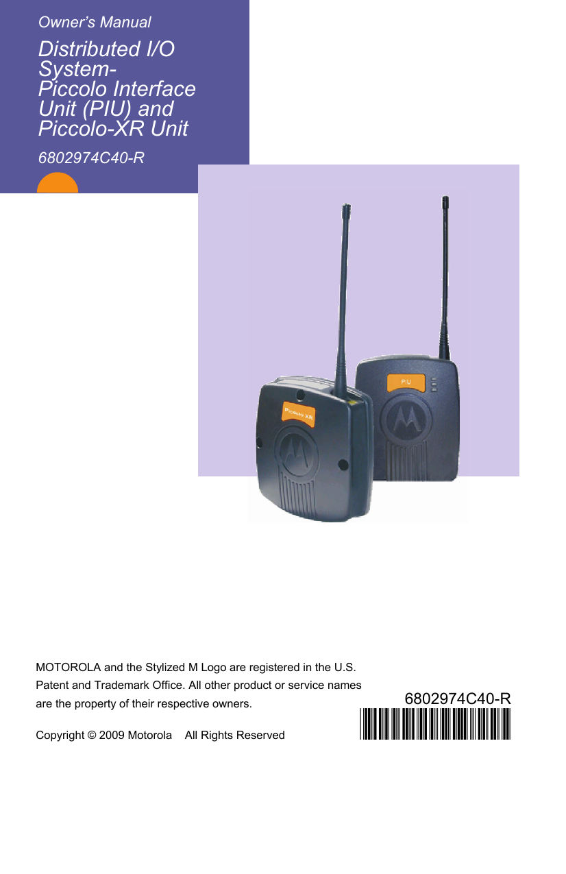
Motorola Solutions 89FT4888 PIU AND PIU-XR OF DIOS User Manual Distributed I O System Owner s Manual
Motorola Solutions, Inc. PIU AND PIU-XR OF DIOS Distributed I O System Owner s Manual
UserManual.wiki
>
Motorola Solutions
>
89FT4888 User Manual
>
Users Manual
Contents
1.
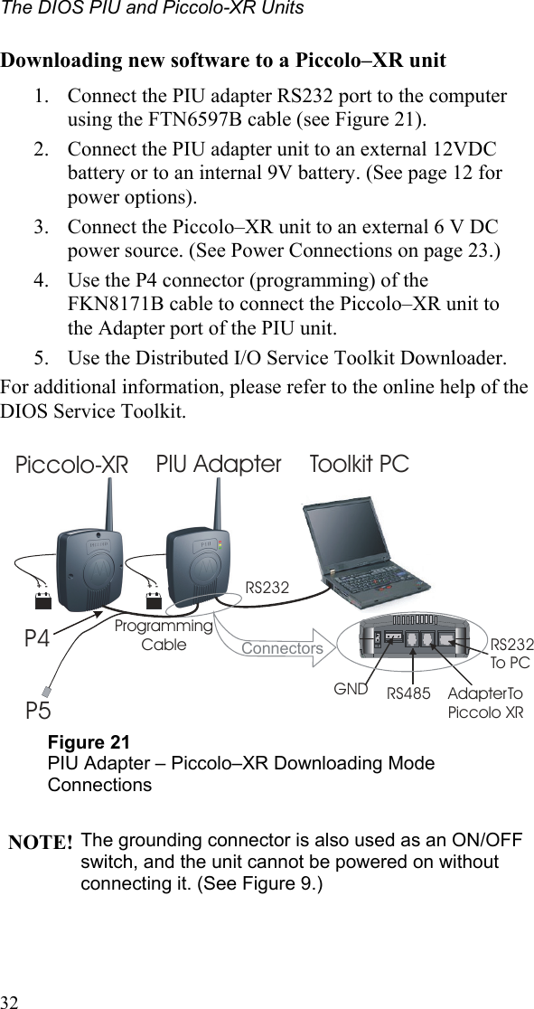
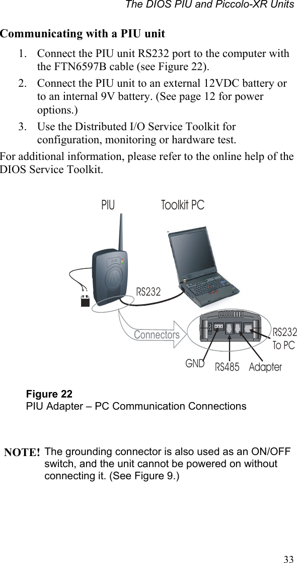
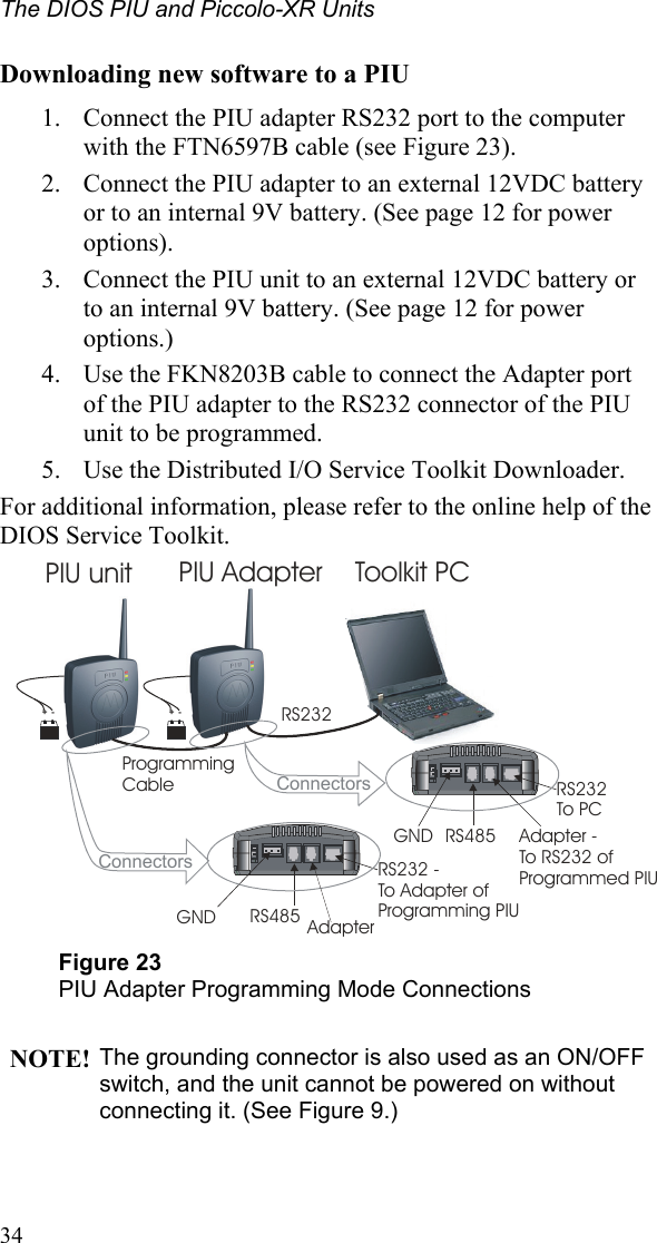
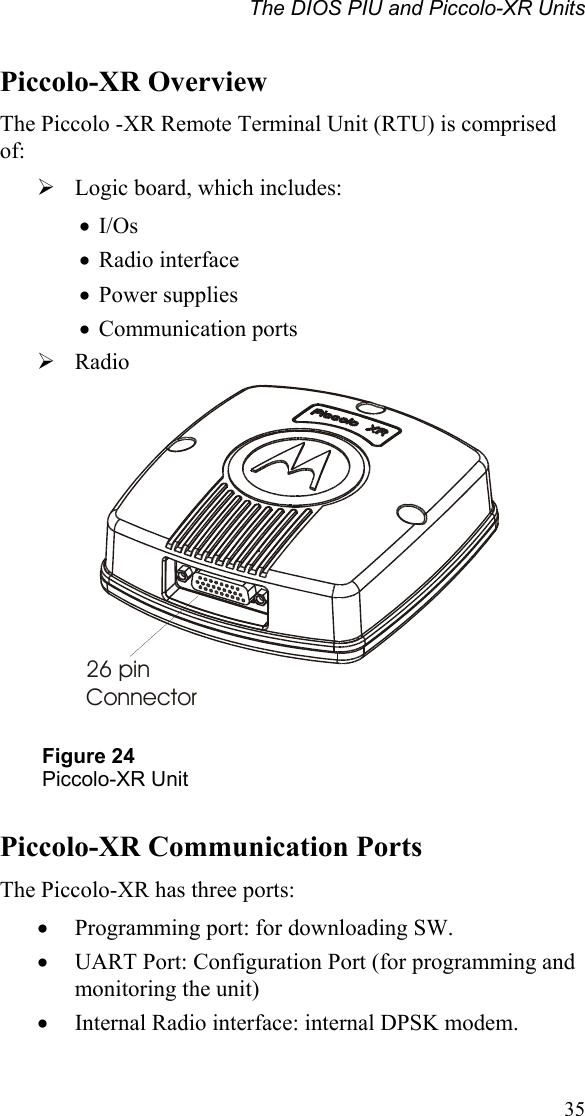
Users Manual
2.
Safety Booklet
Users Manual
Navigation menu
Upload a User Manual
Namespaces
Wiki Guide
HTML
PDF
Info
Views
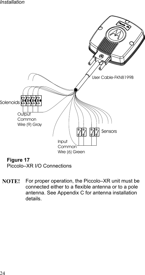
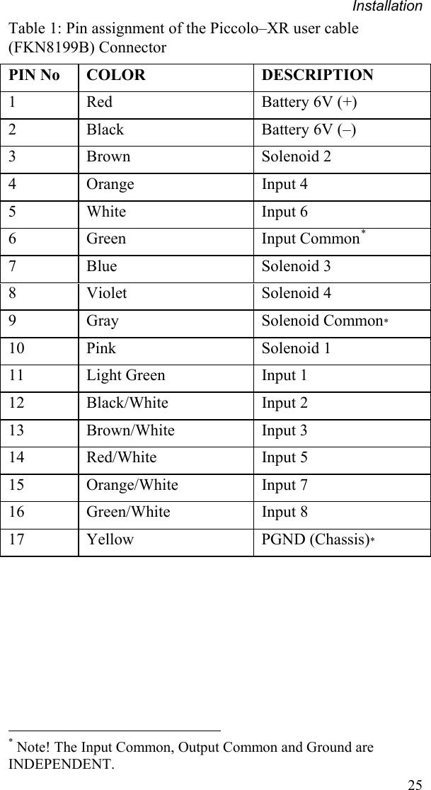
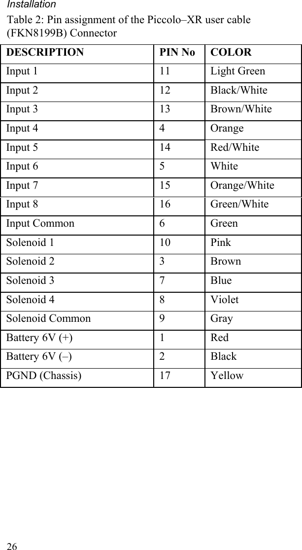
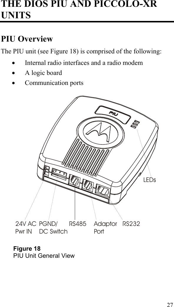
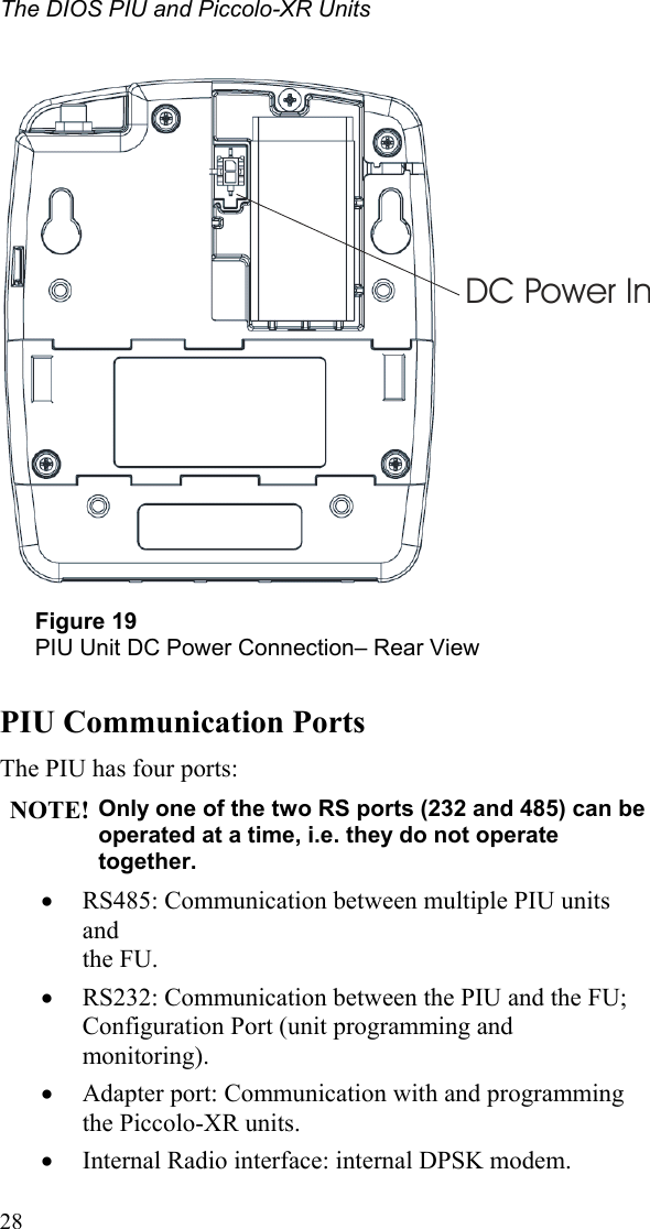
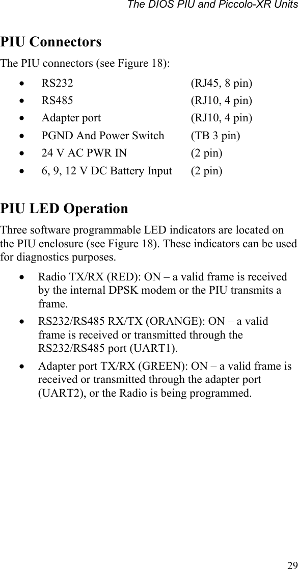
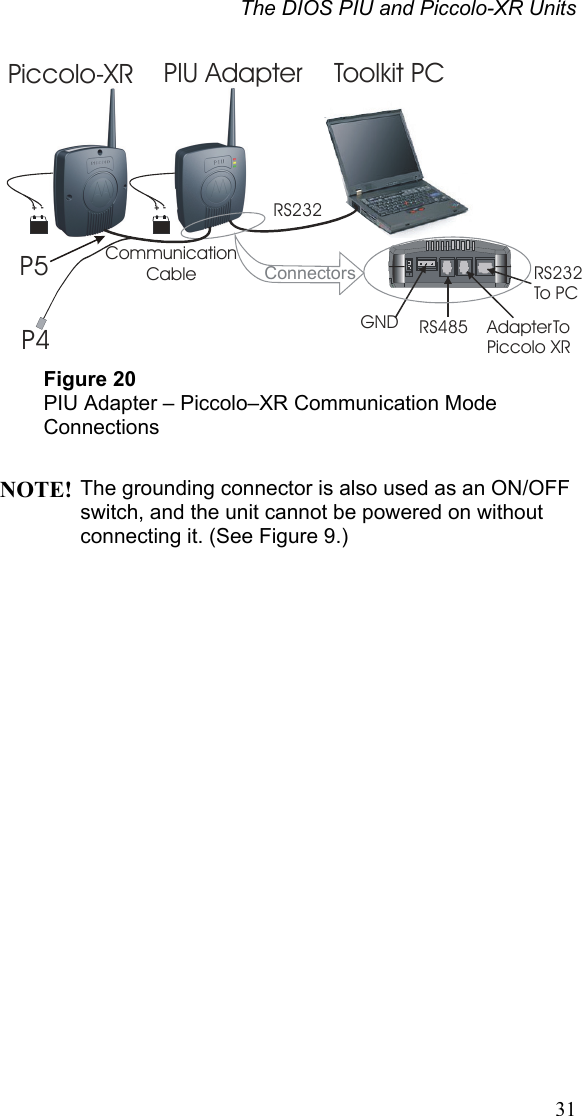
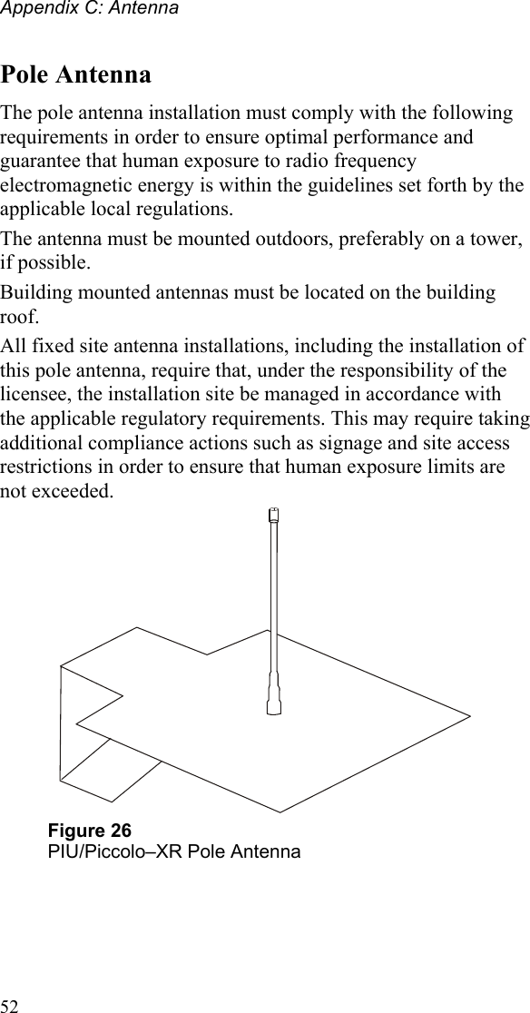
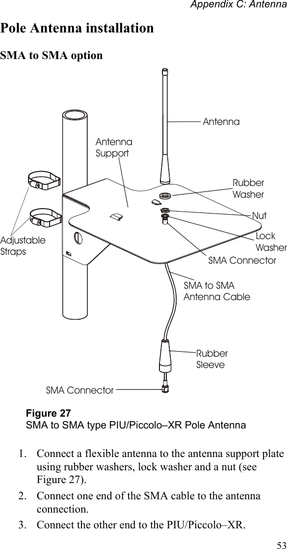
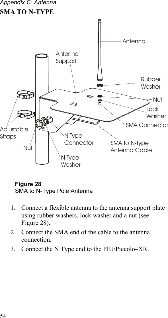
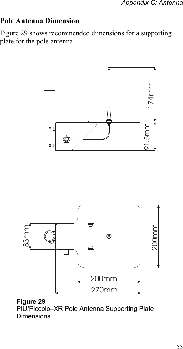
User Manual
Discussion / Help
Navigation