Motorola Solutions 89FT4888 PIU AND PIU-XR OF DIOS User Manual Distributed I O System Owner s Manual
Motorola Solutions, Inc. PIU AND PIU-XR OF DIOS Distributed I O System Owner s Manual
Contents
- 1. Users Manual
- 2. Safety Booklet
Users Manual
Owner’s Manual
Distributed I/O
System-
Piccolo Interface
Unit (PIU) and
Piccolo-XR Unit
6802974C40-R
MOTOROLA and the Stylized M Logo are registered in the U.S.
Patent and Trademark Office. All other product or service names
are the property of their respective owners.
Copyright © 2009 Motorola All Rights Reserved
6802974C40-R
@6802974C40@
COMMERCIAL WARRANTY (STANDARD)
Motorola radio communications products are warranted to be free from defects
in material and workmanship for a period of ONE (1) YEAR, (except for crystals
and channel elements which are warranted for a period of ten (10) years), from
the date of shipment. Parts, including crystals and channel elements, will be
replaced free of charge for the full warranty period but the labor to replace
defective parts will only be provided for one Hundred-Twenty (120) days from
the date of shipment. Thereafter purchaser must pay for the labor involved in
repairing the product or replacing the parts at the prevailing rates together with
any transportation charges to or from the place where warranty service is
provided. This express warranty is extended by Motorola Communications and
Electronics Inc., 1301 E. Algonquin Road, Schaumburg, Illinois 60196, to the
original purchaser only, and only to those purchasing for purpose of leasing or
solely for commercial, industrial, or governmental use.
THIS WARRANTY IS GIVEN IN LIEU OF ALL OTHER WARRANTIES
EXPRESS OR IMPLIED WHICH ARE SPECIFICALLY EXCLUDED,
INCLUDING WARRANTIES OF MERCHANTABILITY OR FITNESS FOR A
PARTICULAR PURPOSE. IN NO EVENT SHALL MOTOROLA BE LIABLE
FOR INCIDENTAL OR CONSEQUENTIAL DAMAGES TO THE FULL EXTENT
SUCH MAY BE DISCLAIMED BY LAW.
In the event of a defect, malfunction or failure to conform to specifications
established by seller, or if appropriate, to specifications accepted by Seller in
writing, during the period shown, Motorola, at its option, will either repair or
replace the product or refund the purchase price thereof, and such action on
the part of Motorola shall be the full extent of Motorola’s liability hereunder.
This warranty is void if:
a. the product is used in other than its normal and customary manner;
b. the product has been subject to misuse, accident neglect or damage;
c. unauthorized alterations or repairs have been made, or unapproved parts
used in the equipment.
This warranty extends only to individual products, batteries are excluded, but
carry their own separate limited warranty. Because each radio system is
unique, Motorola disclaims liability for range, coverage, or operation of the
system as a whole under this warranty except by a separate written agreement
signed by an officer of Motorola.
Non-Motorola manufactured products are excluded from this warranty, but
subject to the warranty provided by their manufacturers, a copy of which will be
supplied to you on specific written request.
To obtain performance of this warranty, purchaser should contact a Motorola
salesperson, or Motorola at the address shown above, attention: Quality
Assurance Department.
This warranty applies only within the United States.
COMPUTER SOFTWARE COPYRIGHTS
The Motorola products described in this instruction manual may include
copyrighted Motorola computer programs stored in semi conductor memories
or other media. Laws in the United States and other countries preserve for
Motorola certain exclusive rights for copyrighted computer programs including
the exclusive right to copy or reproduce in any form the copyrighted computer
program. Accordingly, any copyrighted Motorola computer programs contained
in the Motorola products described in this instruction manual may not be copied
or reproduced in any manner without the express written permission of
Motorola. Furthermore, the purchase of Motorola products shall not be
deemed to grant either directly or by implication, estoppel, or otherwise, any
license under the copyrights, patents or patent applications of Motorola, except
for the normal non-exclusive, royalty free license to use that arises by operation
of law in the sale of a product.
EUROPEAN UNION DIRECTIVE 2002/95/EC CONFORMANCE STATEMENT
Hereby, Motorola declares that these products are in compliance with the
essential requirements and other relevant provisions of Directive 2002/95/EC -
Restriction of Hazardous Substances Directive.
This page left intentionally blank.

i
CONTENTS
CONTENTS................................................................................I
INTRODUCTION....................................................................... 1
Scope of this Manual ......................................................................1
General Description........................................................................1
Safety Handling Instructions.........................................................5
INSTALLATION ........................................................................ 7
General ............................................................................................7
PIU Installation...............................................................................8
Mounting the PIU On A Wall Using Screws................................9
Mounting the PIU Using a Bracket.............................................10
PIU DIN Rail Mounting...............................................................11
PIU Electrical Connections..........................................................12
PIU Antenna Connection.............................................................18
Piccolo–XR Installation ...............................................................19
Piccolo–XR Screw Mounting Options ........................................20
Piccolo–XR Electrical Connections.............................................22
THE DIOS PIU AND PICCOLO-XR UNITS............................ 27
PIU Overview................................................................................27
PIU Communication Ports...........................................................28
PIU Connectors.............................................................................29
PIU LED Operation .....................................................................29
PIU Adapter Operation ...............................................................30
Piccolo-XR Overview ...................................................................35
Piccolo-XR Communication Ports ..............................................35
Piccolo-XR Connector..................................................................36
Contents
ii
APPENDIX A: PIU and PICCOLO-XR SPECIFICATIONS....37
PIU Specifications.........................................................................37
Environmental ................................................................................37
Mechanical .....................................................................................37
PIU Board.......................................................................................38
Power..............................................................................................39
PICCOLO XR Specifications ......................................................42
Environmental ................................................................................42
Mechanical .....................................................................................42
PICCOLO XR Board......................................................................42
Communication Ports .....................................................................43
Power..............................................................................................44
Regulatory Standards ..................................................................46
Radio Network Freq Band Rated Power.......................46
APPENDIX B: MODELS and ACCESSORIES......................49
General ..........................................................................................49
APPENDIX C: ANTENNA ...................................................... 51
General ..........................................................................................51
Flexible Antenna Specifications ..................................................51
Pole Antenna .................................................................................52
Pole Antenna installation.............................................................53
APPENDIX D: PIU/PICCOLO–XR MOUNTING TEMPLATES
.................................................................................................57

INTRODUCTION
Scope of this Manual
This manual provides instructions for the installation and
operation of the Distributed I/O system Piccolo Interface Unit
(PIU) and Piccolo–XR units. The Distributed I/O System
includes PIUs and Piccolo–XRs. Each PIU can be linked to up
to 256 Piccolo–XRs. For more information on the PIU and
Piccolo–XR, see the online help of the DIOS Service Toolkit.
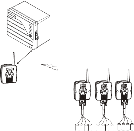
General Description
The Distributed I/O System (DIOS) is a self-sustained system
designed to function within the IRRInet irrigation control
product line.
The DIOS consists of the following components:
Piccolo Interface Unit (PIU)
Piccolo–XR Units
The PIU functions as an interface between the host application
(irrigation SW and HW) and the Piccolo–XR units. The PIU
and Piccolo-XR are portable devices, which are used in fixed
installations. The PIU uses one of its communication ports to
link to the host application and radio communication to link to
the Piccolo–XR units. Figure 1 provides a general view of the
DIOS System.
1
Introduction
2
Piccolo-XR Units
I/O's
IRRInet Field
Unit
Piccolo
Interface
Unit
RS485
or
RS232
PIU
Figure 1
DIOS –General System View
The battery-operated Piccolo–XR unit is available in various
models with different options of Inputs and Outputs. The
Piccolo–XR unit can operate DC latch solenoids (outputs), read
status and calculate flow of dry contact meters (inputs).
The units are equipped with built-in radio for communication
with the PIU.
The DIOS automatically builds communication network, using
Store and Forward (S&F) technology, enabling the DIOS to
cover areas larger than normally possible when using a single
radio to communicate with the PIU.
Using the DIOS, the IRRInet system opens and closes stations
(manually or automatically by irrigation programs), reads dry
contact input status, calculates flow rate and accumulates
pulses from water meters.
Introduction
3
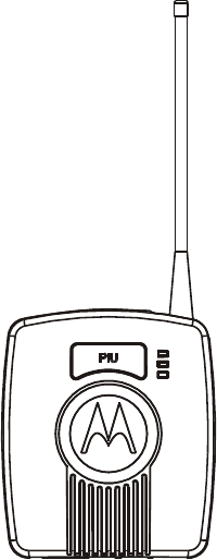
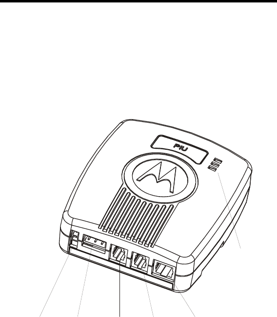
PIU - Piccolo Interface Unit
The Piccolo Interface Unit (PIU; see Figure 2) is connected to
the IRRInet Field Unit (FU) via RS232
or RS485 serial ports.
Each PIU supports up to 256 Piccolo–XR units, with any
available I/O combination, limited by the capacity of the
IRRInet software only.
Utilizing the S&F technology and networking capabilities, the
PIU can be linked to Piccolo–XR units positioned in distances
of up to 1500-2000 meters (approx. 1 mile), depending on
topography, antenna type and antenna installation.
The PIU is an interface between the Piccolo–XR and the
IRRInet FU, which provides communication and networking
operations only. (Monitor and control features are not included
in the PIU.) That is: The control and monitor functions are
provided either locally, by the Piccolo–XR or by an upper
hierarchy unit (i.e. IRRInet FU).
The PIU is a portable device, which is used in fixed
installations enclosed in an indoor plastic housing.
The PIU must be installed by qualified and authorized
technicians, so as to meet applicable safety standards and to
ensure protection against weather hazards for the unit.
If the PIU will be connected to outdoor lines, an interface unit,
complying with Clause 6 of the UL 60950 standard must be
provided.
Introduction
4
Figure 2
PIU – General View
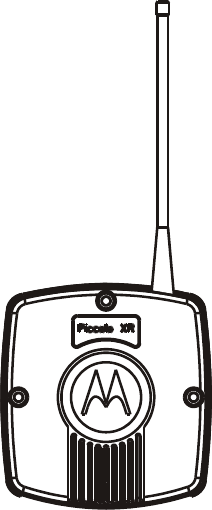
Piccolo–XR
The Piccolo–XR is an intelligent, microprocessor based unit
that can be used to monitor and control local units in a multi
unit communication network. Piccolo–XR units communicate
data to a PIU while functioning as intelligent nodes in
Distributed I/O monitor and control systems. The Piccolo–XR
is often used in irrigation and water distribution systems (i.e.
irrigation valves, water meters, fertilizing meters, various
sensors, flushing filters, and other non-irrigation devices).
The Piccolo–XR is ideal for use in applications where very low
power consumption is essential. The Piccolo–XR is also
available in an outdoor resistant housing (IP66), designed to
resist harsh environment, such as exposure to sun, dust, and
pouring rain.
Introduction
5
Figure 3
Piccolo XR –General View
Safety Handling Instructions
For safety handling instructions, see the Product Safety and RF
Energy Exposure Booklet for PIU and Piccolo XR Units,
Motorola publication no. 6802974C70, which is distributed
with the devices.
The radio frequency band used by the DIOS system has not
been harmonized throughout the entire European Economic
Area (EEA).
Introduction
6
This page left intentionally blank.

INSTALLATION
General
SAFETY SUMMARY
!
C a u t i o n
The PIU and Piccolo–XR must be installed by
qualified and authorized technicians, specifically
qualified to handle high voltage if the installation
involves high-voltage connections/installations.
!
C a u t i o n
If the PIU will be installed outdoors, an outdoor
plastic housing complying with UL60950 standard
clause 6 is required.
Note! See Piccolo–XR Screw Mounting Options
(page 20) for mounting details.
Note! This equipment is tested with specified length
cables and in standard enclosure. If longer cables
or a different enclosure are used, the installer is
responsible to ensure that the installation
complies with the requirements of the applicable
standards.
7
Installation
8
PIU Installation
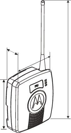
PIU Dimensions
The unit dimensions are (see Figure 4):
Width – 4.25" (108 mm),
Height – 4.96" (126 mm),
Height including antenna – 11.46" (291.1 mm),
Depth – 1.67" (42 .6mm),
Weight – 0.558 lb (253g) maximum.
4.25"
108mm
"
mm
1.67"
42.6mm
11.46
291.1
4.96”
126 mm
Figure 4
Dimensions of PIU Unit
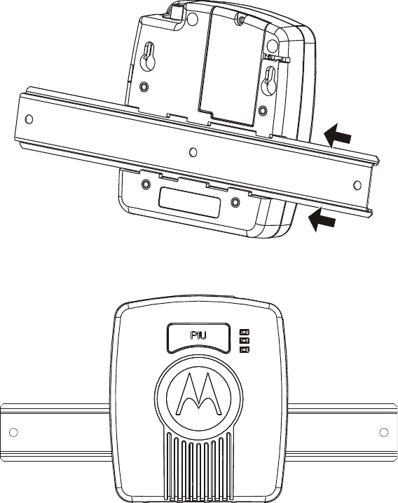
The PIU is enclosed in a plastic housing, allowing 3 mounting
options:
Wall mount (Screws)
Bracket mount
DIN rail mount
Installation
9
Before installing the PIU, verify that there is sufficient space
around the unit according to the specific installation.
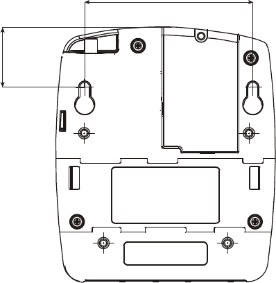
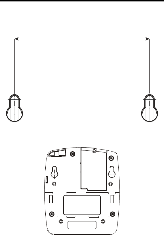
Mounting the PIU On A Wall Using Screws
1. Secure two screws (not supplied) of maximum 0.37"
(9.5 mm) head size to the wall, 3.256" (82.7 mm) apart.
The wall-mounting template in Appendix D can be
used to determine the space between both screws.
2. The screws must not protrude from the wall surface by
more than 0.23” (6 mm) or by less than 0.16" (4 mm).
3. Attach the unit to the wall, fitting the two key hole
shaped cavities on the back cover of the unit over the
screws and sliding it down. (See Figure 5.)
3.26"
82.7 mm
1.19"
30.3mm
Figure 5
PIU Installation– Screw Mount dimensions
Installation
10
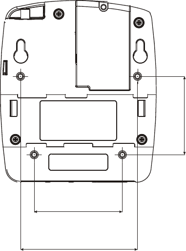
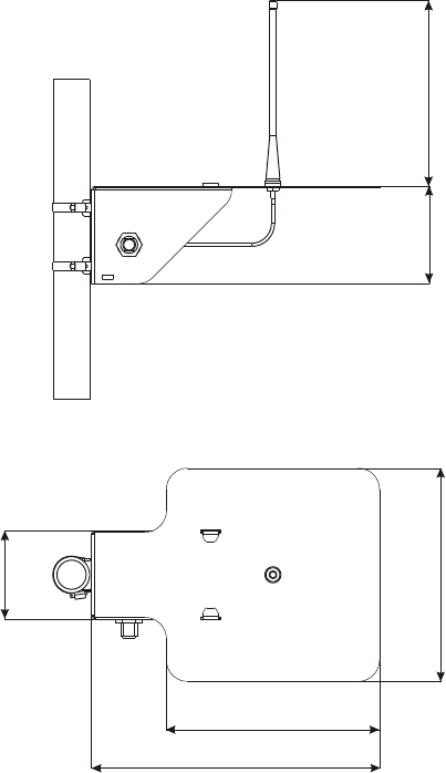
Mounting the PIU Using a Bracket
1. Using four M3x6 or M3x8 screws, attach a bracket
(not supplied) to the back of the PIU. The upper two
bracket holes must be 3.19" (81 mm) apart, and the
lower two bracket holes must be 2.40" (61 mm) apart
and 2.13" (54 mm) below the upper holes, as shown in
Figure 6.
2. Attach the bracket to the mounting surface.
2.13"
54mm
2.40"
61 mm
3.19"
81mm
Figure 6
PIU Installation– Bracket Mount dimension
Installation
12
PIU Electrical Connections
NOTE! Verify that all power connections are made in
accordance with the applicable local standards.
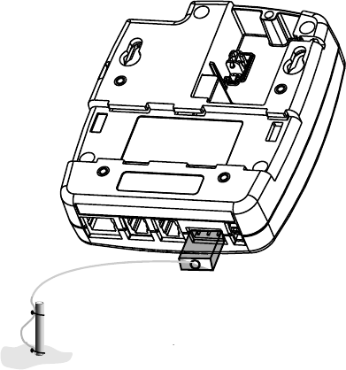
PIU Ground Connections
Use the FKN8254B cable to connect the grounding cable
directly to the TB connector of the PIU as shown in Figure 9.
NOTE! The grounding connector is also used as an
ON/OFF switch, and the unit cannot be powered on
without connecting it.
Grounding Cable
(FKN8254B)
Ground
Figure 9
PIU Ground connection

Installation
13
Power Connection
The PIU can be powered by various types of supply sources:
Internal (9VDC) battery;
External 6V or 12V DC battery;
Motorola power supplies – controllers. For example:
IRRInet XL, IRRInet XM, IRRIcom, MOSCAD;
24VAC.
NOTE! The unit DC voltage range is 6 to 16 volts.
9VDC Internal Battery
!
C a u t i o n
Incorrect replacement of the battery can result in
explosion! Replace only with the same or with an
equivalent type of battery recommended by the
manufacturer.
Dispose of used batteries according to the battery
manufacturer instructions.
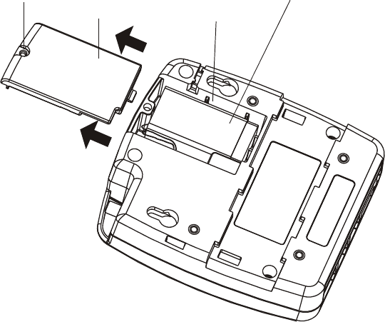
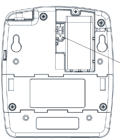
Place a standard 9VDC alkaline battery (not supplied) into the
PIU battery chamber (see Figure 10). Battery operation is
applicable when operating the unit in a non-radio mode, e.g.
when the PIU is used as an adapter.
Installation
14
Installation of an Internal Battery
1. Release the screw at the top of the battery chamber
door, and slide the door out, as shown in Figure 10.
2. Connect the 9V battery cable (FKN8204B) to the DC
power input connector on the back of the unit.
3. Connect the 9V DC battery to the cable.
4. Place the 9V DC alkaline battery in the chamber as
shown in Figure 10.
5. Close the battery chamber door and secure with the
screw.
Screw Battery
Chamber Door
Battery
Chamber
Battery
Figure 10
PIU Battery Chamber
Installation
15
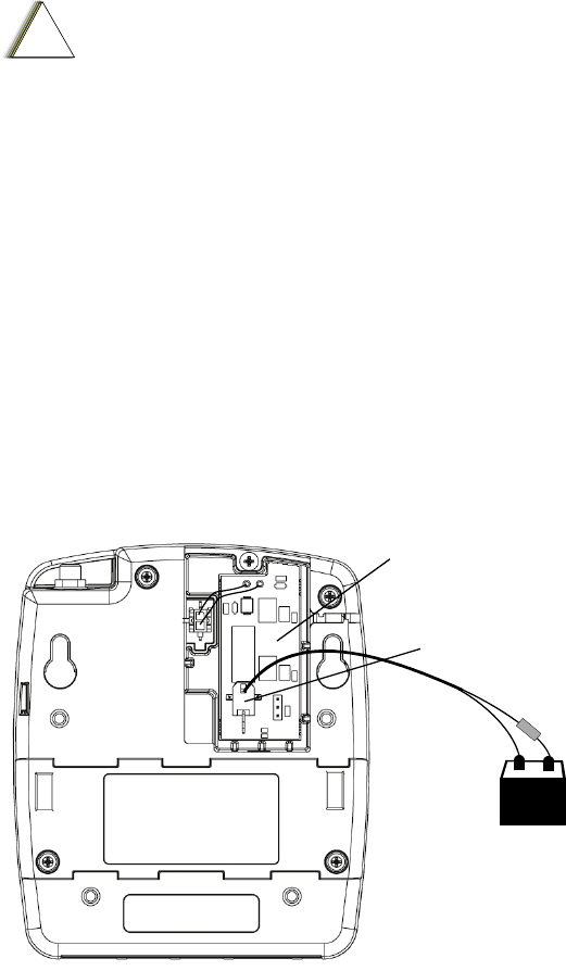
External Battery Power Connections
!
C a u t i o n
The unit must be powered by a limited power
source (12V DC) in accordance with standard
UL/IEC 60950-1. See Power in Appendix A below.
This connection is used for normal operation of the PIU, when
radio communication is required, or when RS485 or RS232
ports are used.
1. Release the screw at the top of the battery chamber
door and slide the door out, as shown in Figure 10.
2. Connect the DC Adapter board (FCN6538B) to the DC
power input connector on the back of the unit (Figure
11).
3. Connect the FKN8250B 7 ft cable to the DC Adapter
board.
4. Connect the other cable end to an external 12VDC
battery through 1A fuse (not supplied).
5. Close the battery chamber door and secure with the
screw.
+-
1A Fus
e
DC adapter board
FCN6538B
DC power in
FKN8250B
Figure 11
PIU Unit – Rear View with DC Adapter
Installation
16
External Power Supply Connections
Use the applicable cable from the V152AH PIU installation kit
to connect the PIU to Motorola standard controller power
supply.
1. Release the screw at the top of the battery chamber
door and slide the door out, as shown in Figure 10.
2. Connect one end of the cable to the DC power input
connector on the back of the unit.
3. Connect the other end of the cable to the power supply
output of a Motorola controller.
4. Close the battery chamber door and secure with the
screw.
Installation
17
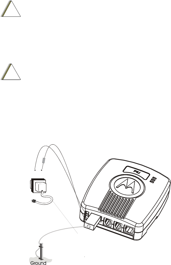
24VAC Power Connections
!
C a u t i o n
The PIU must be connected to a power source
equivalent to one or more of the following:
a. A listed Direct plug-in unit.
b. A Class II power source (defined by the
National Electrical Code (NEC) and the
Canadian Electrical Code (CEC).
c. A power source that complies with UL1950
C1.2.1 or UL60950 C1.2.5.
!
C a u t i o n
The unit must be powered by a limited power
source (24V AC) in accordance with the UL/IEC
60950-1 standard. See Power in Appendix A
below.
1. Connect the FKN8264B cable to the 24 V AC PWR IN
connector as shown in Figure 12.
2. Connect the other end of the cable to the 24 V AC
connection of a 110 V AC/220 V AC transformer (not
supplied) through a 1 A fuse (not supplied).
1A Fuse
24 V AC
0
~
110/220 V AC
AC Cable
FKN8264B
Figure 12
24VAC Power In Connection
Installation
18
PIU Antenna Connection
Flexible Antenna: Attach the flexible monopole antenna to the
antenna connector at the top of the unit. See Appendix C for
detailed information.
Pole Antenna: Attach the FKN8258B antenna cable to the
antenna connector at the top of the unit. Connect the other end
of the antenna cable to a customer-supplied pole antenna. See
Appendix C for detailed information.
Installation
19
Piccolo–XR Installation
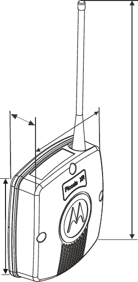
Piccolo–XR Dimensions
The unit dimensions are (see Figure 13):
Width – 4.6" (117 mm)
Height – 5.00" (127 mm)
Hight including antenna – 11.46" (291.1 mm)
Depth –1.63" (41.5mm)
Weight – 0.54 lb (240 gr) maximum.
11.46"
291.1mm
5.00”
127 mm
1.63"
41.5mm
4.6"
117mm
Figure 13
Dimensions of the Piccolo–XR Unit
Installation
20
The Piccolo–XR unit can be attached to any vertical or
horizontal surface using screws. Before mounting the Piccolo–
XR, verify that sufficient clearance is left around the unit.
Allow 8" (20 cm) clearance off the bottom of the Piccolo–XR
case for the user cable and 6.3" (16 cm) off the top of the unit
for the flexible antenna.
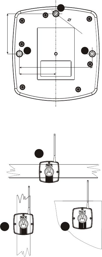
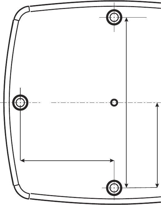
Piccolo–XR Screw Mounting Options
Mount the Piccolo–XR on a vertical surface as follows:
Secure the unit to any vertical surface using one 0.35"
(9 mm) maximum head screw. Use the mounting hole
marked A in Figure 14 to attach it to the mounting surface.
See Figure 15 B.
Mount the Piccolo–XR on a horizontal surface as
follows:
Secure the unit to any horizontal surface using two 0.35"
(9 mm) maximum head screws. Use the mounting holes
marked B and C in Figure 14 to attach it to the mounting
surface. See Figure 15 A.
Mount the Piccolo–XR on a wide plane as follows:
Secure the unit to any plane using three 0.35" (9 mm)
maximum head screws. Use all three mounting hole marked A,
B and C in Figure 14 to attach it to the mounting surface. See
Figure 15 C.
Installation
21
A
B C
54
mm
98mm
49mm
3x 4.75
Figure 14
Piccolo–XR Mounting Screw holes – Back View
C
B
A
Figure 15
Piccolo–XR Mounting Options
Installation
22
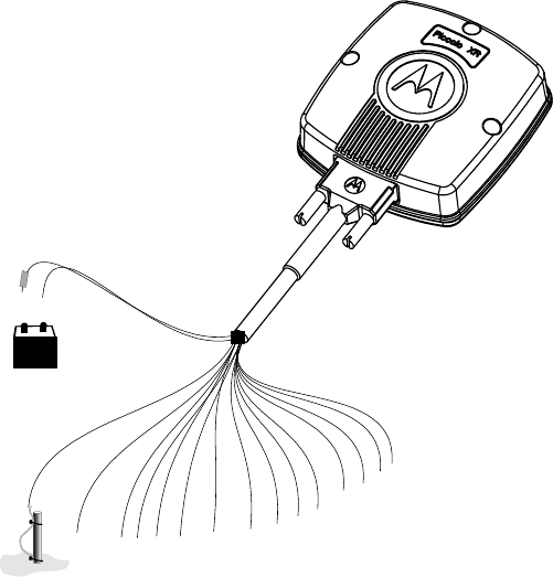
Piccolo–XR Electrical Connections
NOTE! Verify that all power connections are made in
accordance with the applicable local standards.
+-
Ground
6 V DC Battery
Wire (1)-Red
W
ire (2)-Black
Wire (17)-Yellow
User Cable-FKN8199B
I/O's
1A Fuse
Figure 16
Piccolo–XR Ground and DC Power Connections
Piccolo–XR Ground Connections
Connect the yellow wire (17) of the FKN8199B user cable to
the PGND, as shown in Figure 16.

Installation
23
Power Connections
!
C a u t i o n
The unit must be powered by a limited power
source (6V DC) in accordance with standard
UL/IEC 60950-1. See Power in Appendix A below.
The Piccolo–XR is powered by an external 6V DC battery
source.
Use the FKN8199B cable to connect the Piccolo–XR to an
external battery. Connect Wire #1 (red) to the positive (+) pole
of the battery through a 1A fuse (not supplied) and wire #2
(black) to the battery negative (–) pole. See Figure 16.
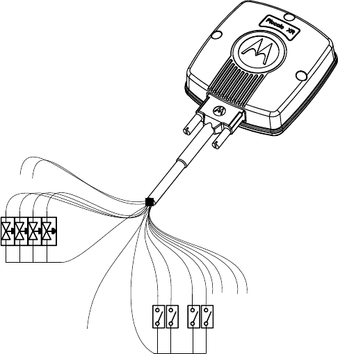
I/O Connections
The Piccolo–XR RTU can control up to four DC Latch
Solenoids.
The solenoid operating voltage can vary in the range of +9 to
+20V DC (defined by the site configuration definition in the
DIOS Service Toolkit).
The Piccolo–XR also responds to back indication signals from
a maximum of eight different field input sensors.
The available I/O module options are as follows:
1 DI / 1 DO
2 DI / 2 DO
4 DI / 4 DO
7 DI / 1DO
8 DI / 0DO
Installation
24
Output
Common
Wire (9) Gray
Input
Common
W
ire (6) Green
Solenoids
Sensors
User Cable-FKN8199B
Figure 17
Piccolo–XR I/O Connections
NOTE! For proper operation, the Piccolo–XR unit must be
connected either to a flexible antenna or to a pole
antenna. See Appendix C for antenna installation
details.

Installation
25
Table 1: Pin assignment of the Piccolo–XR user cable
(FKN8199B) Connector
PIN No COLOR DESCRIPTION
1 Red Battery 6V (+)
2 Black Battery 6V (–)
3 Brown Solenoid 2
4 Orange Input 4
5 White Input 6
6 Green Input Common*
7 Blue Solenoid 3
8 Violet Solenoid 4
9 Gray Solenoid Common*
10 Pink Solenoid 1
11 Light Green Input 1
12 Black/White Input 2
13 Brown/White Input 3
14 Red/White Input 5
15 Orange/White Input 7
16 Green/White Input 8
17 Yellow PGND (Chassis)*
* Note! The Input Common, Output Common and Ground are
INDEPENDENT.

Installation
26
Table 2: Pin assignment of the Piccolo–XR user cable
(FKN8199B) Connector
DESCRIPTION PIN No COLOR
Input 1 11 Light Green
Input 2 12 Black/White
Input 3 13 Brown/White
Input 4 4 Orange
Input 5 14 Red/White
Input 6 5 White
Input 7 15 Orange/White
Input 8 16 Green/White
Input Common 6 Green
Solenoid 1 10 Pink
Solenoid 2 3 Brown
Solenoid 3 7 Blue
Solenoid 4 8 Violet
Solenoid Common 9 Gray
Battery 6V (+) 1 Red
Battery 6V (–) 2 Black
PGND (Chassis) 17 Yellow
The DIOS PIU and Piccolo-XR Units
28
DC Power In
Figure 19
PIU Unit DC Power Connection– Rear View
PIU Communication Ports
The PIU has four ports:
NOTE! Only one of the two RS ports (232 and 485) can be
operated at a time, i.e. they do not operate
together.
• RS485: Communication between multiple PIU units
and
the FU.
• RS232: Communication between the PIU and the FU;
Configuration Port (unit programming and
monitoring).
• Adapter port: Communication with and programming
the Piccolo-XR units.
• Internal Radio interface: internal DPSK modem.
The DIOS PIU and Piccolo-XR Units
29
PIU Connectors
The PIU connectors (see Figure 18):
• RS232 (RJ45, 8 pin)
• RS485 (RJ10, 4 pin)
• Adapter port (RJ10, 4 pin)
• PGND And Power Switch (TB 3 pin)
• 24 V AC PWR IN (2 pin)
• 6, 9, 12 V DC Battery Input (2 pin)
PIU LED Operation
Three software programmable LED indicators are located on
the PIU enclosure (see Figure 18). These indicators can be used
for diagnostics purposes.
• Radio TX/RX (RED): ON – a valid frame is received
by the internal DPSK modem or the PIU transmits a
frame.
• RS232/RS485 RX/TX (ORANGE): ON – a valid
frame is received or transmitted through the
RS232/RS485 port (UART1).
• Adapter port TX/RX (GREEN): ON – a valid frame is
received or transmitted through the adapter port
(UART2), or the Radio is being programmed.
The DIOS PIU and Piccolo-XR Units
30
PIU Adapter Operation
The PIU can be used as an adapter to perform the following
functions:
• Communicating with the Piccolo–XR for
configuration, monitoring or hardware test.
• Downloading new software to a Piccolo–XR unit.
• Downloading new software to a PIU unit.
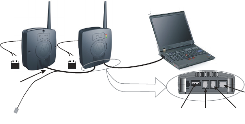
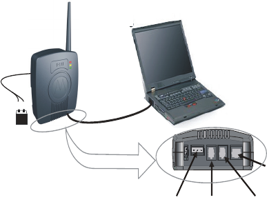
Communicating With a Piccolo–XR Unit
1. Connect the PIU adapter RS232 port to the computer
with the FTN6597B cable (see Figure 20).
2. Connect the PIU adapter unit to an external 12VDC
battery or to an internal 9V battery. (See page 12 for
power options).
IMPORTANT: Ensure that there is a 20 cm safety
distance between the PIU adapter unit and the user’s
body when connecting the battery.
3. Use the Distributed I/O Service Toolkit to turn off the
radio’s power.
4. Connect the Piccolo–XR unit to an external 6VDC
power source. (See Power Connections on page 23.)
5. Use the P5 connector (communication) of the
FKN8171B cable to connect the Piccolo–XR unit to
the Adapter port of the PIU unit.
6. Use the Distributed I/O Service Toolkit to configure
and monitor the Piccolo–XR or to test its hardware.
For additional information, please refer to the online help of the
DIOS Service Toolkit.
The DIOS PIU and Piccolo-XR Units
31
Piccolo-XR
PIU Adapter Toolkit P
C
RS232
Communication
Cable
RS232
To PC
Adapter To
Pi
cco
l
o
XR
GND RS485
Connectors
+-
+-
P4
P5
Figure 20
PIU Adapter – Piccolo–XR Communication Mode
Connections
NOTE! The grounding connector is also used as an ON/OFF
switch, and the unit cannot be powered on without
connecting it. (See Figure 9.)
The DIOS PIU and Piccolo-XR Units
32
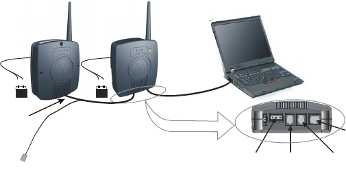
Downloading new software to a Piccolo–XR unit
1. Connect the PIU adapter RS232 port to the computer
using the FTN6597B cable (see Figure 21).
2. Connect the PIU adapter unit to an external 12VDC
battery or to an internal 9V battery. (See page 12 for
power options).
3. Connect the Piccolo–XR unit to an external 6 V DC
power source. (See Power Connections on page 23.)
4. Use the P4 connector (programming) of the
FKN8171B cable to connect the Piccolo–XR unit to
the Adapter port of the PIU unit.
5. Use the Distributed I/O Service Toolkit Downloader.
For additional information, please refer to the online help of the
DIOS Service Toolkit.
RS232
Programming
Cable
RS232
To PC
Adapter To
Piccolo XR
GND RS485
Connectors
+-
+-
P
5
P4
Piccolo-XR PIU Adapter Toolkit P
C
Figure 21
PIU Adapter – Piccolo–XR Downloading Mode
Connections
NOTE! The grounding connector is also used as an ON/OFF
switch, and the unit cannot be powered on without
connecting it. (See Figure 9.)
The DIOS PIU and Piccolo-XR Units
33
Communicating with a PIU unit
1. Connect the PIU unit RS232 port to the computer with
the FTN6597B cable (see Figure 22).
2. Connect the PIU unit to an external 12VDC battery or
to an internal 9V battery. (See page 12 for power
options.)
3. Use the Distributed I/O Service Toolkit for
configuration, monitoring or hardware test.
For additional information, please refer to the online help of the
DIOS Service Toolkit.
PIU Toolkit P
C
RS232
RS232
To PC
Adapter
GND RS485
Connectors
+-
Figure 22
PIU Adapter – PC Communication Connections
NOTE! The grounding connector is also used as an ON/OFF
switch, and the unit cannot be powered on without
connecting it. (See Figure 9.)
The DIOS PIU and Piccolo-XR Units
34
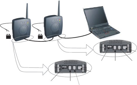
Downloading new software to a PIU
1. Connect the PIU adapter RS232 port to the computer
with the FTN6597B cable (see Figure 23).
2. Connect the PIU adapter to an external 12VDC battery
or to an internal 9V battery. (See page 12 for power
options).
3. Connect the PIU unit to an external 12VDC battery or
to an internal 9V battery. (See page 12 for power
options.)
4. Use the FKN8203B cable to connect the Adapter port
of the PIU adapter to the RS232 connector of the PIU
unit to be programmed.
5. Use the Distributed I/O Service Toolkit Downloader.
For additional information, please refer to the online help of the
DIOS Service Toolkit.
RS232
Programming
Cable
RS232
To PC
A
dapter -
To RS232 of
Programmed PIU
GND RS485
Connectors
+-
+-
Connectors
RS232 -
To Adapter of
Programming PIU
A
da
p
ter
GND RS485
PIU unit PIU Adapter Toolkit P
C
Figure 23
PIU Adapter Programming Mode Connections
NOTE! The grounding connector is also used as an ON/OFF
switch, and the unit cannot be powered on without
connecting it. (See Figure 9.)
The DIOS PIU and Piccolo-XR Units
35
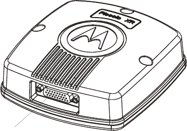
Piccolo-XR Overview
The Piccolo -XR Remote Terminal Unit (RTU) is comprised
of:
¾ Logic board, which includes:
• I/Os
• Radio interface
• Power supplies
• Communication ports
¾ Radio
26 pin
Connector
Figure 24
Piccolo-XR Unit
Piccolo-XR Communication Ports
The Piccolo-XR has three ports:
• Programming port: for downloading SW.
• UART Port: Configuration Port (for programming and
monitoring the unit)
• Internal Radio interface: internal DPSK modem.
The DIOS PIU and Piccolo-XR Units
36
Piccolo-XR Connector
The Piccolo -XR has one D-type 26 pin connector (see
Figure 24). See Table 1 and Table 2 on pages 25–26 for more
information
Input/Output options
A variety of I/O options is available for use with the
Piccolo-XR, increasing the system flexibility.
The available Piccolo-XR I/O options are:
• 1 DI / 1 DO
• 2 DI / 2 DO
• 4 DI / 4 DO
• 7 DI / 1DO
• 8 DI / 0DO
For option numbers, see Appendix B below.

APPENDIX A: PIU and PICCOLO-XR
SPECIFICATIONS
PIU Specifications
Environmental
Operating Temperature -30 C to +60 C (-22 F to +140 F)
Storage Temperature -40 C to +85 C (-40 F to + 185 F)
Relative Operating
Humidity
0 to 95% without condensation
@ +50 C (122 F)
Operating Altitude -400 m to +4000 m
(-1300 ft to 13,000 ft) above sea level
Mechanical
Dimensions 126x108x42.6 mm 1 mm
(4.96"x4.25"x1.67")
Weight 253 gr 25 gr (0.56 lb 0.06 lb)
User Connection
RS232 (RJ45)
Adapter port (RJ10)
RS485 (RJ10)
PGND and DC switch (TB 3 PIN)
24 VAC (Molex header
2 PIN)
6V, 9V, 12V DC
BAT IN (Straight 2 PIN)
37

APPENDIX A: PIU AND PICCOLO-XR SPECIFICATIONS
38
PIU Board
Communication Ports
RS232 Serial RS-232
RS485 Multi Drop 2 Wire
Adapter Serial interface between PIU as
adapter and PICCOLO–XR
(UART levels)
Boot-Strap Software programming port
Internal Radio
RF Frequency UHF 450–470 MHz (actually
450.0125-469.9875) OR
UHF 430-450 MHz (actually
430.0125-449.9875)* **
(Service Toolkit programmable)
Duty Cycle ratio < 10% (relative to a 1 hour period
for ISM band only)
Channel spacing 12.5 KHz
Internal Modem DPSK 1200
TX RF Low power mode: 8 – 12 mW @+25 C (+77 F)
(10 mW typical)
5 – 16.3 mW @–30 C - +60 C
(-22 F to 140 F)
TX RF High power
mode:
80 – 108 mW @+25 C (+77 F)
(100 mW typical)
50 – 108 mW @–30 C - +60 C
Frequency Error: 1.5 ppm
* Includes unlicensed ISM (intended for industrial, scientific and
medical purposes) band: Center frequency: 433.92 MHz, Frequency
range: 433.05–434.79 MHz (actually 433.0625-434.7875 MHz) in
Region 1. See Unlicensed Frequency Restrictions below.
** Not including 443.95 MHz and 444.8625 MHz.

APPENDIX A: PIU AND PICCOLO-XR SPECIFICATIONS
39
TX deviation: 2KHz 15%
RX BER BER<1% (See Note 5 on p. 41.)
LEDs Red, Orange, Green
(SW Programmable)
Power
Input Voltage
External Source
(DC Power In)
6.00 to 16.00 VDC e.g. lead acid
battery or solar panel, typically used
in irrigation systems.
External Source
(24V ~ IN)
24VAC±20%, typically from
transformer to 110VAC or 220VAC.
Power Modes
Adapter Mode (Using the internal 9 V battery)
Normal Operation 1 – 5 mA (See Note 4 on p. 41.)
Sleep Mode
LPM0 250 – 400 μA (See Note 1 on p. 41.)
LPM3 140 – 290 μA (See Note 1 on p. 41.)
Power Fail Mode
LPM3 270 – 850 μA (See Note 3 on p. 41.)

APPENDIX A: PIU AND PICCOLO-XR SPECIFICATIONS
40
PIU Mode (Using a 12 V or 6 V external power source)
Radio Transmission
(TX power-10 mW) 25 – 40 mA (PWR IN =14 V)
65 – 90 mA (PWR IN = 6 V)
(TX power-100 mW) 30 – 65 mA (PWR IN =14 V)
85 – 135 mA (PWR IN = 6 V)
Standby current
Radio Receives
13 – 18 mA (PWR IN =14 V)
30 – 38 mA (PWR IN = 6 V)
Sleep Mode
LPM0 200 – 320 μA (See Note 2 on p.
41.)
LPM3 130 – 250 μA (See Note 2 on p.
41.)
Power Monitors
Power OK Voltage (Service Toolkit Adjustable Default
= 12 V DC) 200 mV
LOW Power Voltage (Service Toolkit Adjustable Default
= 11.2 V DC) 200 mV
Very Low Battery (Service Toolkit Adjustable Default
= 10.8 V DC) 200 mV
Reverse Input Voltage
Connection
Protected
APPENDIX A: PIU AND PICCOLO-XR SPECIFICATIONS
41
Note 1: Power In = 9 V DC (Adapter), RS232 = shutdown,
RS485 = disable, Radio (On Board Circuits) = off, internal
Radio is off. RS232 cable connected.
Note 2: Power Supply = 14 V DC (PIU), RS232 = shutdown,
RS485 = disable, Radio (On Board Circuits) = off, internal
Radio is off. RS232 cable connected.
Note 3: Power In = 5.4 V DC (Power fail), RS232 =
shutdown, RS485 = disable, Radio (On Board Circuits) = off,
internal Radio is off. RS232 cable connected.
Note 4: Power In = 9 V DC (Adapter), RS232 = auto
shutdown, RS485 = disable, Radio (On Board Circuits) = off,
internal Radio is off. RS232 cable connected.
Note 5: Apply 1.2 KHz FM signal with 2 KHz Deviation,
Sensitivity @–110 dBm to the radio, and read BER. At
extreme temperatures apply –104 dBm.
PICCOLO XR Specifications
Environmental
Operating Temperature -30 C to +60 C
(-22 F to +140 F)
Storage Temperature -40 C to +85 C
(-40 F to + 185 F)
Relative Operating
Humidity
0 to 95% without condensation
@ +50 C (122 F)
Operating Altitude -400 m to +4000 m (-1300 ft to
13,000 ft) above sea level
Housing IP66
APPENDIX A: PIU AND PICCOLO-XR SPECIFICATIONS
42
Mechanical
Dimensions
127x117x41.5 mm 1 mm
(5.00"x4.60"x1.63")
Weight
240 gr 24 gr (0.54 lb 0.05 lb)
User Connection 17 pin User Cable
(26 pin D-type connector)
Wire Gauge 22 AWG
PICCOLO XR Board
INPUTS:
Number of Inputs Modularity: 1, 2, 4, 7, 8
Dry contact Input Ratings Open: > 45 k (OFF)
Closed: < 6 k (ON)
Minimum pulse width 100 msec
Maximum pulse rate 7200 pulses per hour
OUTPUTS:
Number of Outputs Modularity: 1, 2, 4
Output Drive Voltage 9 - 20 Volts (± 10%) (Service
Toolkit Adjustable)-
2200 µF capacitor
Output Short Circuit
Protection
>5 A
Communication Ports
UART 1 port Serial port uart levels (Async.)
UART 2 port Serial port UART levels (Async.)
Bootstrap Port Software programming port

APPENDIX A: PIU AND PICCOLO-XR SPECIFICATIONS
43
Internal Radio
RF Frequency UHF 450–470 MHz or
UHF 430-450 MHz * **
(Service Toolkit programmable)
Duty Cycle ratio < 10% (relative to a 1 hour period
for ISM band only)
Channel spacing 12.5 KHz
Internal Modem DPSK 1200
TX RF Low power mode: 8 – 12 mW @+25 C (+77 F)
(10 mW typical)
5 – 16.3 mW @–30 C - +60 C
(-22 F to 140 F)
TX RF High power
mode:
80 – 108 mW @+25 C (+77 F)
(100 mW typical)
50 – 108 mW @–30 C - +60 C
Frequency Error 1.5 ppm
TX deviation 2KHz 15%
RX BER BER<1% (See Note 10 on p. 44.)
Power
Input Voltage
External Battery Source 4 to 7.8 V DC (See Note 11 p. 45.)
Power Consumption (6 V battery operation)
Normal Operating Mode:
* Includes unlicensed ISM (intended for industrial, scientific and
medical purposes) band: Center frequency: 433.92 MHz, Frequency
range: 433.05–434.79 MHz (actually 433.0625-434.7875 MHz) in
Region 1. See Unlicensed Frequency Restrictions below.
** Not including 443.95 MHz and 444.8625 MHz.

APPENDIX A: PIU AND PICCOLO-XR SPECIFICATIONS
44
Radio Transmission
Radio Off 1.2 – 1.5 mA (See Notes 6, 7 p. 44.)
(TX power-10mW) 65 – 90 mA (See Notes 8, 9 p. 44.)
(TX power-100mW)
100 – 150 mA (See Notes 8, 9 p. 44.)
Radio Receives 30 – 40 mA (See Notes 8, 9 p. 44.)
Sleep Mode
LPM0
190 – 250 μA (See Note 7 p. 44.)
LPM3 40 – 65 μA (See Note 7 p. 44.)
Power Fail Mode
LPM3
40 – 70 μA (See Note 6 p. 44.)
Power Monitors
Power In Report 200 mV
Power OK Voltage Service Toolkit Adjustable
Default = 6 V DC 200 mV
Low Power Voltage Service Toolkit Adjustable
Default = 5 V DC 200 mV
Very Low Battery Service Toolkit Adjustable
Default = 4.8 V DC 200 mV
Reverse Input Voltage
Connection
Protected
Note 6: Power In = 4 V DC, Radio (On Board Circuits) = Off,
internal Radio is off.
Note 7: Power In = 7.8 V DC, Radio (On Board Circuits) =
Off, internal Radio is off.
Note 8: Power In = 5.5 V DC, Radio (On Board Circuits) =
On, internal Radio is On.
Note 9: Power In = 7.8 V DC, Radio (On Board Circuits) =
On, internal Radio is On.
Note 10: Apply 1.2 KHz FM signal with 2 KHz Deviation,
Sensitivity @-110 dBm to the radio, and read BER. At
extreme temperatures apply -104 dBm.
APPENDIX A: PIU AND PICCOLO-XR SPECIFICATIONS
45
Note 11: For radio functionality external Power In minimum
voltage=5 V.
Unlicensed Frequency Restrictions
(For UHF 430-450 MHz radio only) When using a frequency
in the unlicensed ISM range (433.0625-434.7875 MHz, not
including 443.95 MHz and 444.8625 MHz), certain
regulatory restrictions apply:
Maximum transmit power 10mW (See Note 12 below.)
Maximum transmission time 1 sec (See Note 13 below.)
Channel occupation duty cycle
(total transmit time in any hour)
10% per hour (360 seconds)
(See Note 14 below.)
Transmission Limited to quiet channel (See
Note 15 below.
Override Not allowed
When Piccolo XR / PIU units are ordered in the unlicensed
ISM range (433.0625 - 434.7875 MHz), the radio will be
shipped after being programmed to 10 mW output power.
Note 12: Please note that due to the lower transmission
power, the distance between the Piccolo and the PIU is
shorter than the distance when using a licensed frequency
with 100 mW transmission power.
Note 13: The current consumption of the Piccolo will
increase due to the fact that the Maximum transmission time
is reduced and therefore the Piccolo should wake up more
frequently.
Note 14: The maximum number of transmissions from the
PIU/Piccolo is limited to 360 per hour. When this number is
exceeded, the PIU/Piccolo will stop transmitting until the
current hour has elapsed.
Note 15: The PIU/Piccolo will not transmit on a busy
channel. Verify that the frequency you choose in the band is
not continually busy.

APPENDIX A: PIU AND PICCOLO-XR SPECIFICATIONS
46
Regulatory Standards
US and Canada Grant of Equipment Authorization
IMPORTANT: Unauthorized repairs or modifications could
result in permanent damage to the equipment and void your
warranty and your authority to operate this device under Part
15 of the FCC Rules.
FCC Grant of Equipment Authorization
FCC ID: AZ489FT4888
FCC ID: AZ489FT4871
Industry Canada Grant of Equipment Authorization
ID: 109U-89FT4888
ID: 109U-89FT4871
This Class B digital apparatus complies with Canadian ICES-
003.
Radio Network Freq Band Rated Power
FM UHF 430-450MHz 100mW
FM UHF 450-470MHz 100mW
FCC INTERFERENCE
This device complies with Part 15 of the FCC Rules.
Operation is subject to the following two conditions:
1) This device may not cause harmful interference.
2) This device must accept any interference received,
including interference that may cause undesired operation.
For detailed product safety and RF exposure, refer to the
Product Safety and RF Energy Exposure Booklet for PIU and
APPENDIX A: PIU AND PICCOLO-XR SPECIFICATIONS
47
Piccolo XR Units, Motorola publication no. 6802974C70,
which is distributed with the devices.
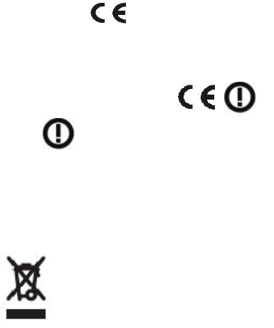
European Union Notification
The CE mark is the official marking required by the European
Community for all Electric and Electronic equipment that will
be sold, or put into service for the first time, anywhere in the
European community.
It proves to the buyer or user that this product fulfills all
essential safety and environmental requirements as they are
defined in the European Directives.
The product approved for unlicensed band 433.05-434.79
Mhz is marked with the mark.
The product approved for licensed band 430-450 MHz
marked with the following CE marks, , carries
the alert symbol to denote that the product band range
of 430-450 MHz is not harmonized in all EU member states.
Equipment Disposal
Please do not dispose of Electronic and Electric Equipment or
Electronic and Electric Accessories with your household
waste. In some countries or regions, collection systems have
been set up to handle waste of electrical and electronic
equipment. In European Union countries, please contact your
local equipment supplier representative or service center for
information about the waste collection system in your
country.
Waste (Disposal) of
Electronic and Electric
Equipment
APPENDIX A: PIU AND PICCOLO-XR SPECIFICATIONS
48
Conformity for RoHS Compliance
This Motorola product is in compliance with the essential
requirements and other relevant provisions of Directive
2002/95/EC, Restriction of the use of certain Hazardous
Substances (RoHS) in electrical and electronic equipment.
49
APPENDIX B: MODELS and
ACCESSORIES
General
The following tables describe the available models, options
and accessories.
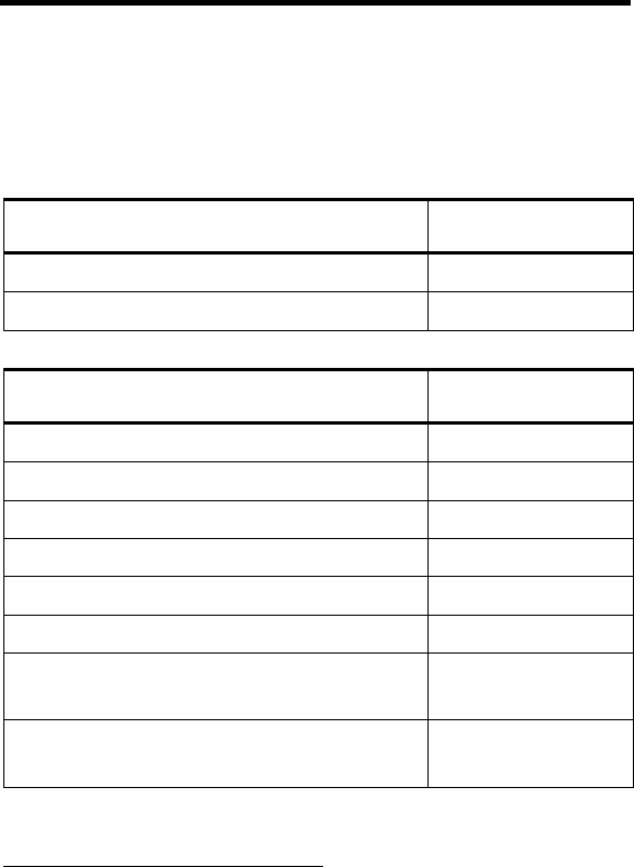
DIOS Models Model
Piccolo Interface Unit (PIU) F4604B
Piccolo–XR DC F4614B
PIU Options Option
ADD: RS-485 Option (indoor) V440AD
ADD: RS-232 Cable 3 m V666AA
ADD: Antenna for PIU, 450-470 MHz V208AJ
ADD: Antenna for PIU, 430-450 MHz V208AL
ADD: PIU Adapter V345AM
ADD: PIU DIOS Application V377AD
INT: 12.5 KHz UHF Radio,
450–470 MHz
V347CT/
FLE6036C
INT: 12.5 KHz UHF Radio,
430–450 MHz ∗ **
V347CU/
FLE5532A
∗ Includes unlicensed ISM (intended for industrial, scientific and
medical purposes) band: Center frequency: 433.92 MHz, Frequency
range: 433.05–434.79 MHz (actually 433.0625-434.7875 MHz)in
Region 1.
** Not including 443.95 MHz and 444.8625 MHz.

Appendix B: Models and Accessories
50
Piccolo-XR Options Option
ADD: 1 DI / 1DO Option V608AE
ADD: 2 DI / 2DO Option V379AK
ADD: 4 DI / 4DO Option V118AJ
ADD: 7 DI / 1 DO Option V115AN
ADD: 8 DI / 0 DO V508AF
ADD: Antenna for Piccolo–XR,
450-470 MHz
V208AH
ADD: Antenna for Piccolo–XR,
430-450 MHz
V208AK
INT: 12.5 KHz UHF Radio,
450–470 MHz
V347CT/
FLE6036C
INT: 12.5 KHz UHF Radio,
430–450 MHz ∗ **
V347CU/
FLE5532A
Accessories Kit number
TEC Programming & Monitoring Cable
(26 pin)
FKN8171B
Pole Antenna Kit (SMA TO SMA) FAE5534B
Pole Antenna Kit (SMA TO N-TYPE) FLN3373B
APPENDIX C: ANTENNA
General
The PIU and Piccolo–XR units can be connected either to a
flexible or to a pole antenna.
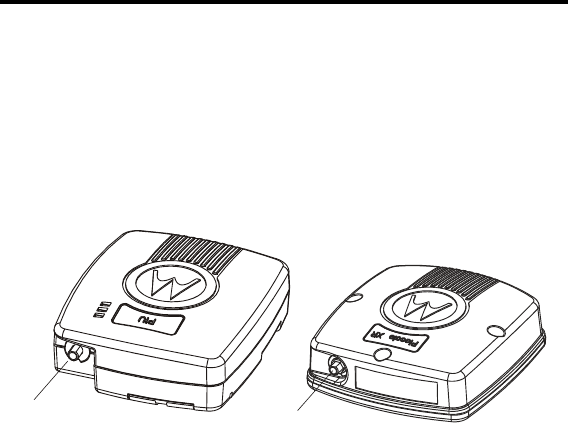
The antenna connector (see Figure 25), located at the top of the
unit, is used for both antenna types.
PIU
Antenna SMA Connector
A
ntenna
S
MA
Co
nn
ec
t
o
r
Piccolo - XR
Figure 25
PIU and Piccolo–XR Antenna Connectors
Flexible Antenna Specifications
Frequency Range: UHF
Polarization: Vertical
Nominal Impedance: 50 ohms
VSWR: 1.5:1 max at resonance
Power Rating 50 watts
Temperature Range: -40ºC to +85ºC
51
Appendix C: Antenna
52
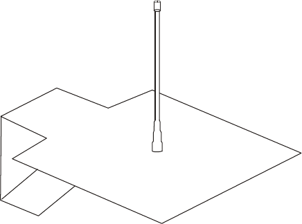
Pole Antenna
The pole antenna installation must comply with the following
requirements in order to ensure optimal performance and
guarantee that human exposure to radio frequency
electromagnetic energy is within the guidelines set forth by the
applicable local regulations.
The antenna must be mounted outdoors, preferably on a tower,
if possible.
Building mounted antennas must be located on the building
roof.
All fixed site antenna installations, including the installation of
this pole antenna, require that, under the responsibility of the
licensee, the installation site be managed in accordance with
the applicable regulatory requirements. This may require taking
additional compliance actions such as signage and site access
restrictions in order to ensure that human exposure limits are
not exceeded.
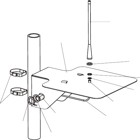
Figure 26
PIU/Piccolo–XR Pole Antenna
Appendix C: Antenna
53
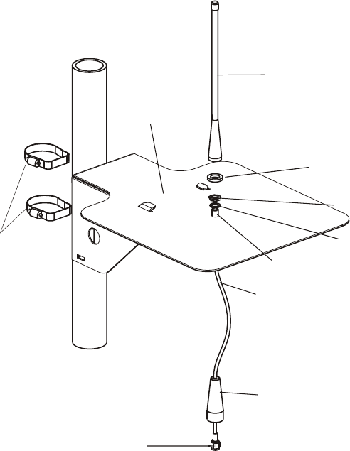
Pole Antenna installation
SMA to SMA option
Antenna
Antenna
Support
Rubber
Washer
Nut
Lock
W
asher
SMA Connector
SMA to SMA
Antenna Cable
Rubber
Sleeve
Adjustable
Straps
SMA Connector
Figure 27
SMA to SMA type PIU/Piccolo–XR Pole Antenna
1. Connect a flexible antenna to the antenna support plate
using rubber washers, lock washer and a nut (see
Figure 27).
2. Connect one end of the SMA cable to the antenna
connection.
3. Connect the other end to the PIU/Piccolo–XR.
Appendix C: Antenna
54
SMA TO N-TYPE
A
ntenna
A
ntenna
Support
Rubber
Washer
Nut
Lock
Washer
SMA Connecto
r
SMA to N-Type
Antenna Cable
N-Type
Connector
N-Type
Washer
Nut
Adjustable
Straps
Figure 28
SMA to N-Type Pole Antenna
1. Connect a flexible antenna to the antenna support plate
using rubber washers, lock washer and a nut (see
Figure 28).
2. Connect the SMA end of the cable to the antenna
connection.
3. Connect the N Type end to the PIU/Piccolo–XR.
Appendix C: Antenna
56
This page left intentionally blank.
57
APPENDIX D: PIU/PICCOLO–XR
MOUNTING TEMPLATES
Use the following template for PIU wall mounting.
3.26"
82.7mm
Figure 30
PIU Wall Mounting Template (Full Size)
Figure 31
PIU Back
Appendix D: PIU/Piccolo – XR Mounting Templates
58
The following is a template that can be used for mounting the
Piccolo–XR unit.
2.126"
54mm
3.86"
98mm
1.93"
49mm
Figure 32
Piccolo–XR Mounting Template (Full Size)

MOTOROLA and the Stylized M Logo are registered in the U.S.
Patent and Trademark Office. All other product or service names
are the property of their respective owners.
Copyright © 2009 Motorola All Rights Reserved
6802974C40-R
@6802974C40@
August 2009