Motorola Solutions 89FT7002 Handheld or Belt mounted data terminal with two Sp User Manual AC EX08
Motorola Solutions, Inc. Handheld or Belt mounted data terminal with two Sp AC EX08
Contents
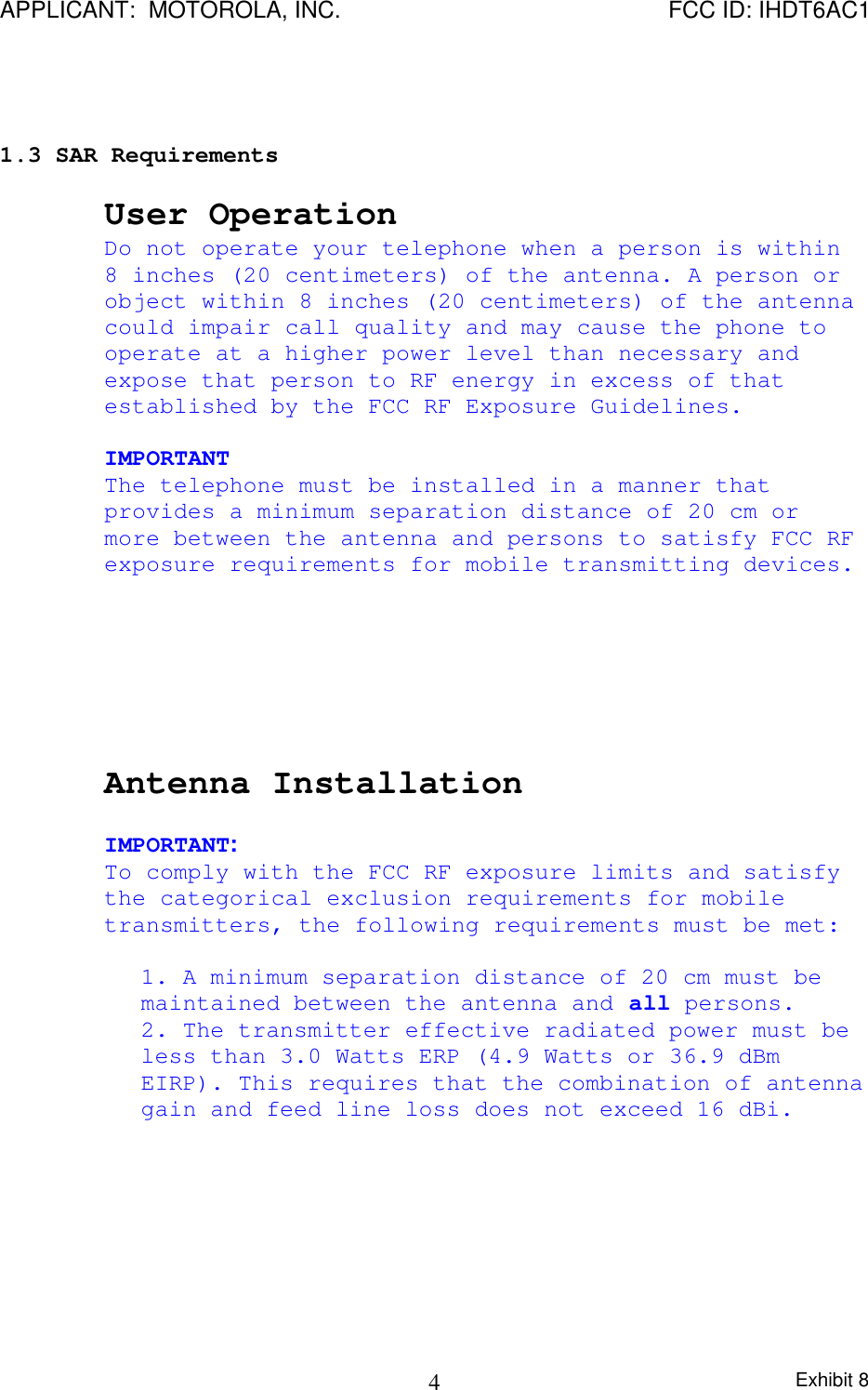
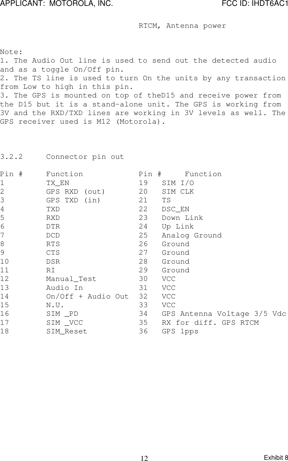
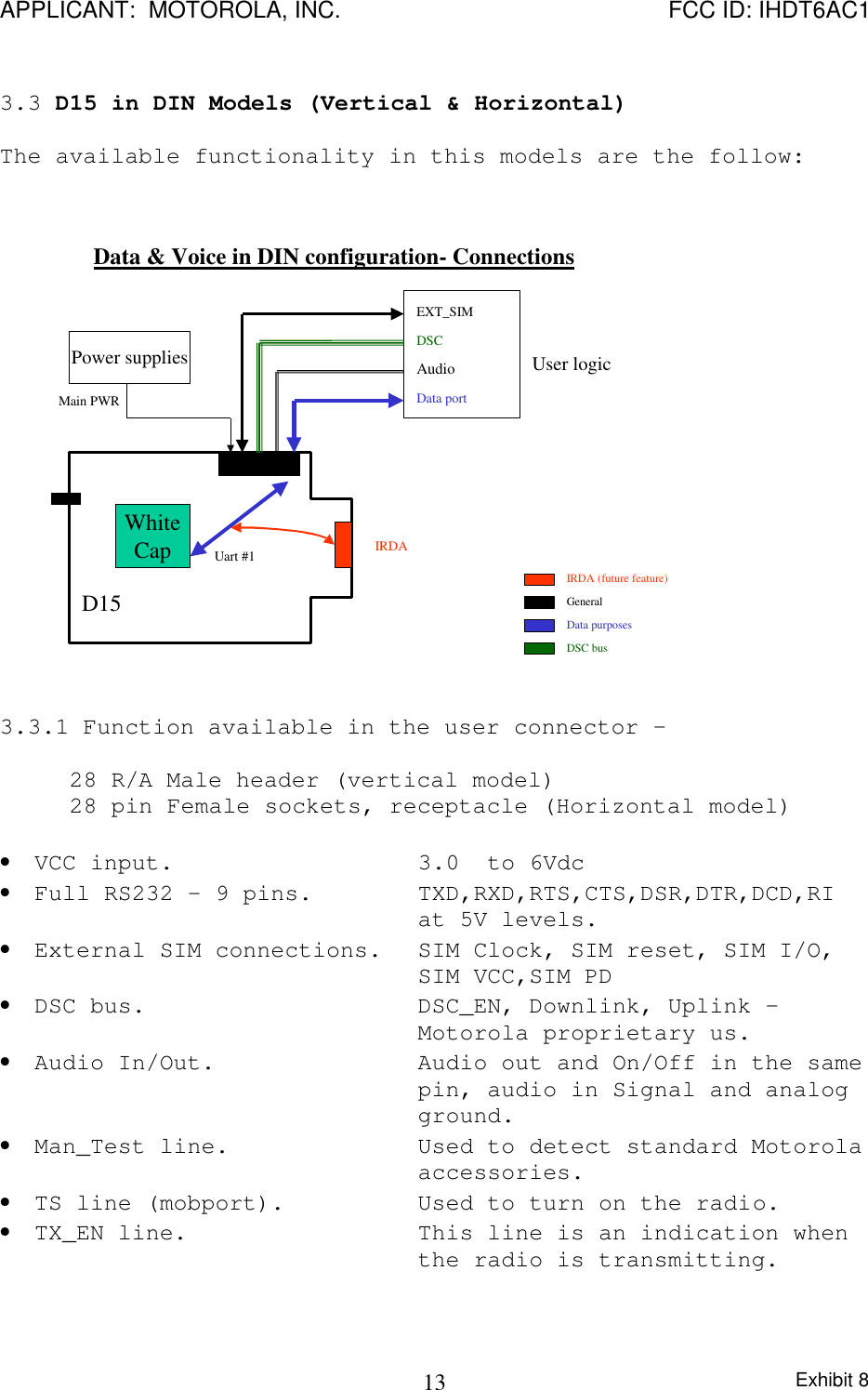
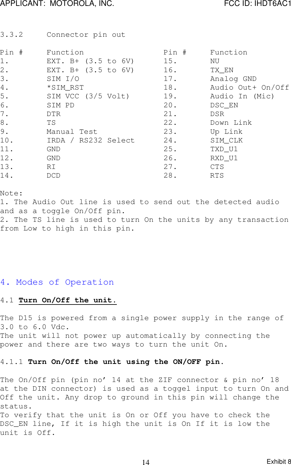
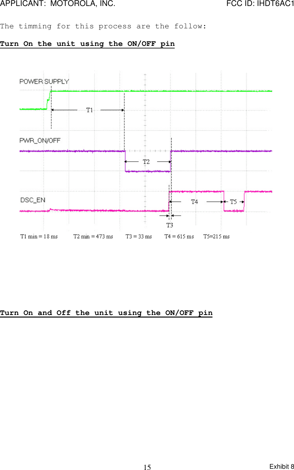
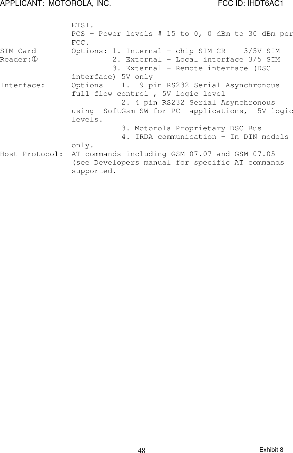
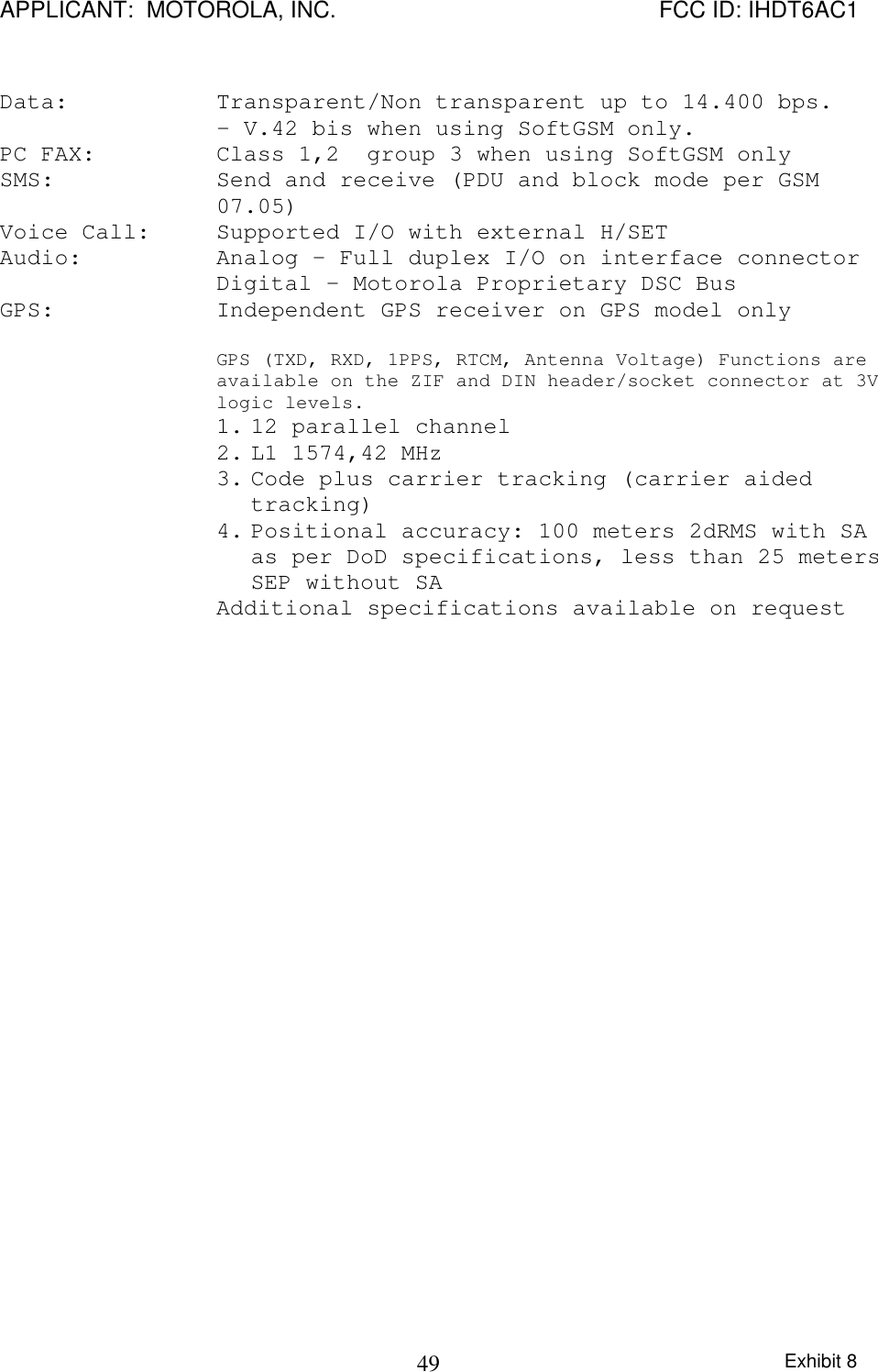
- 1. Exhibit 8 Instruction Manual
- 2. Reference original Exhibit 8 User Manual
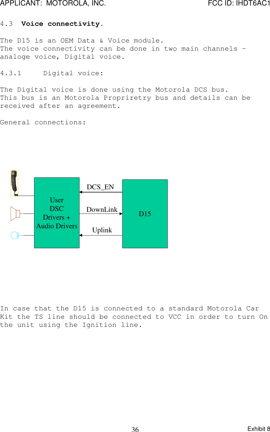
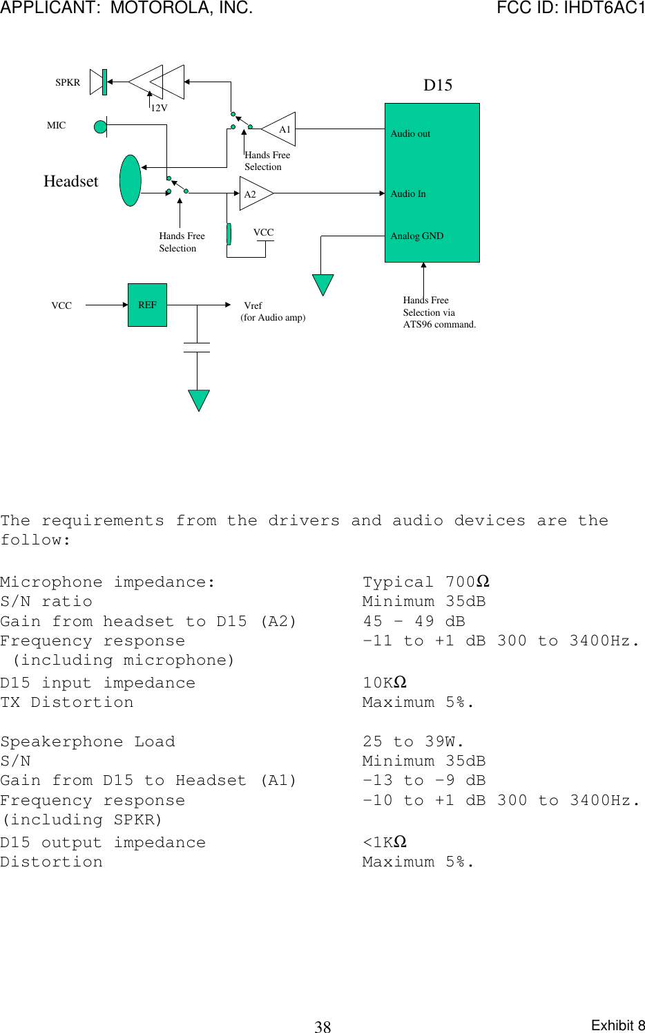
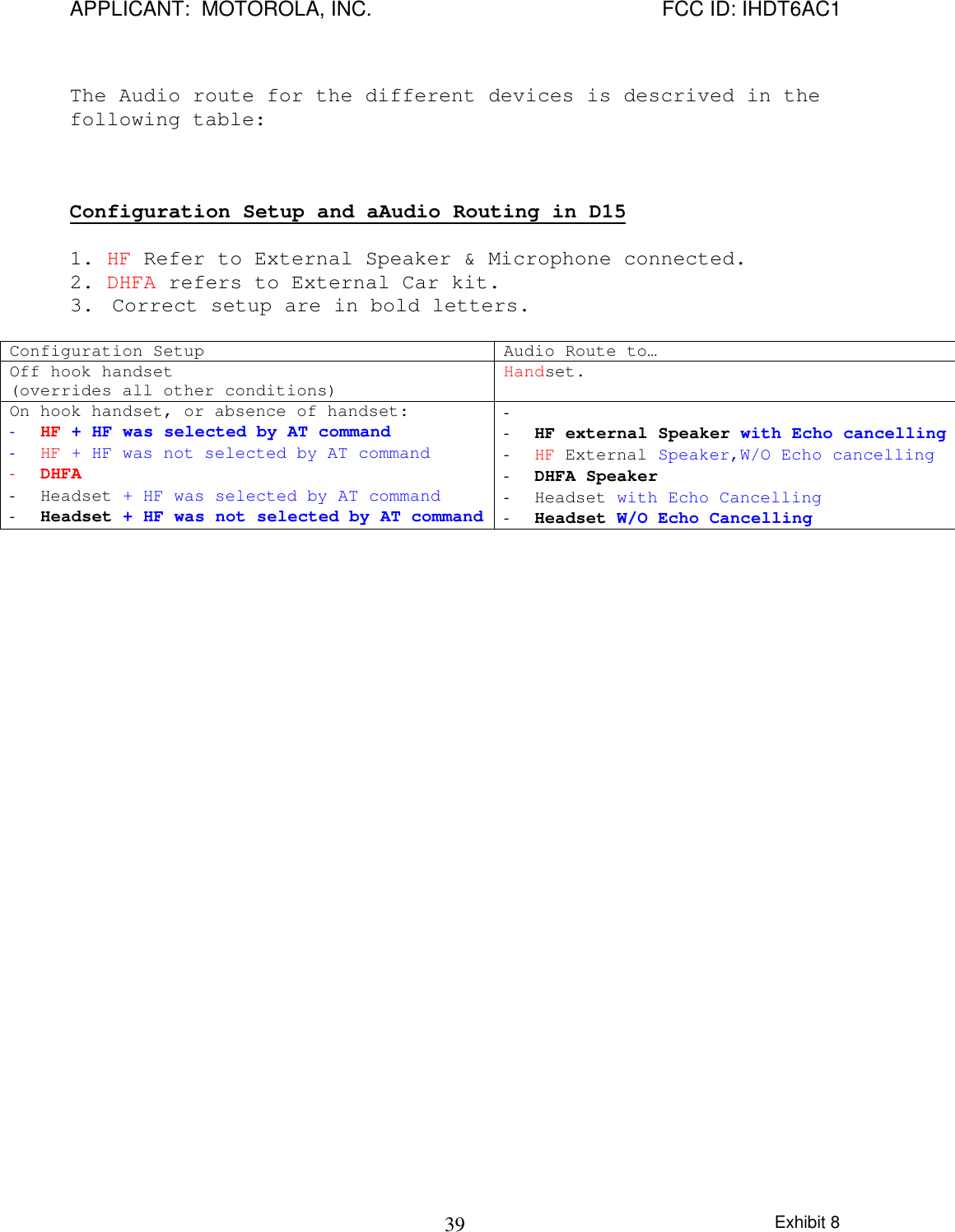
Reference original Exhibit 8 User Manual