Motorola Solutions 89FT7002 Handheld or Belt mounted data terminal with two Sp User Manual AC EX08
Motorola Solutions, Inc. Handheld or Belt mounted data terminal with two Sp AC EX08
Contents
- 1. Exhibit 8 Instruction Manual
- 2. Reference original Exhibit 8 User Manual
Reference original Exhibit 8 User Manual

APPLICANT: MOTOROLA, INC. FCC ID: IHDT6AC1
EXHIBIT 8
INSTRUCTION MANUAL
A preliminary draft copy of the Users Manual follows. RF exposure information is located in section 1.3.
APPLICANT: MOTOROLA, INC. FCC ID: IHDT6AC1
Exhibit 8
1
D15 – Developer Guide – 1st draft
1. Introduction
Product description
The D15 model
Main application
SAR Requirements.
2. Installation
Mechanical description
Connections
3. Pin description & main Functionality
Pin description of connectors per model
Different communication & application
4. Modes of Operation
On/Off process include time diagram
Voice connection
Full flow control data call
Soft GSM Operation
5. Design Consideration
Power supply
Antenna
Data level (VOH, VOL)
Flex cable & external SIM Connector
Environmental
6 Testing & service
How to test a unit in a voice call
How to test a unit in a data call
How to test a unit in a soft GSM call
How to test RF features
Desense test
7. Appendix
1st. Specification
2nd. A list of AT command
3rd. Desense test
APPLICANT: MOTOROLA, INC. FCC ID: IHDT6AC1
Exhibit 8
2
1. Introduction
1.1 Product Specification – See in Appendix bellow.
To add a note thal all the Data/Audio/SIM signals are
compatible with D10
User
Device D10
30 pin FC
D15
User
Device
36 pin FC
3 lines removed
from each side
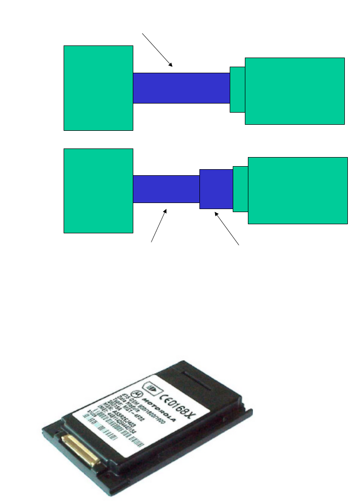
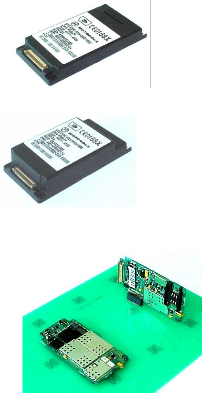
1.2 D15 Models:
• D15 DV (DV= Data & Voice) Standard.
APPLICANT: MOTOROLA, INC. FCC ID: IHDT6AC1
Exhibit 8
3
• D15 DV Slim
• D15 DVG Slim (DVG= Data, Voice, GPS)
• D15 DV Board only (Vertical version & Horizontal version)
APPLICANT: MOTOROLA, INC. FCC ID: IHDT6AC1
Exhibit 8
4
1.3 SAR Requirements
User Operation
Do not operate your telephone when a person is within
8 inches (20 centimeters) of the antenna. A person or
object within 8 inches (20 centimeters) of the antenna
could impair call quality and may cause the phone to
operate at a higher power level than necessary and
expose that person to RF energy in excess of that
established by the FCC RF Exposure Guidelines.
IMPORTANT
The telephone must be installed in a manner that
provides a minimum separation distance of 20 cm or
more between the antenna and persons to satisfy FCC RF
exposure requirements for mobile transmitting devices.
Antenna Installation
IMPORTANT:
To comply with the FCC RF exposure limits and satisfy
the categorical exclusion requirements for mobile
transmitters, the following requirements must be met:
1. A minimum separation distance of 20 cm must be
maintained between the antenna and all persons.
2. The transmitter effective radiated power must be
less than 3.0 Watts ERP (4.9 Watts or 36.9 dBm
EIRP). This requires that the combination of antenna
gain and feed line loss does not exceed 16 dBi.
APPLICANT: MOTOROLA, INC. FCC ID: IHDT6AC1
Exhibit 8
5
2. Installation – See details in PRD.
Configuration 1 with d10 mounting
Configuration 1
Configuration 1 with narrower mounting
with narrower mounting
APPLICANT: MOTOROLA, INC. FCC ID: IHDT6AC1
Exhibit 8
6
Configuration 1 with narrower mounting
Configuration 2
Configuration 2
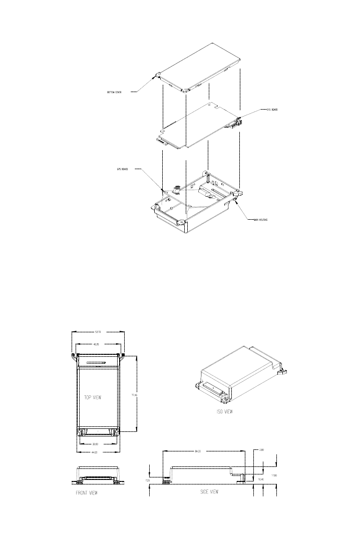
APPLICANT: MOTOROLA, INC. FCC ID: IHDT6AC1
Exhibit 8
7
Configuration 2
Configuration 2
APPLICANT: MOTOROLA, INC. FCC ID: IHDT6AC1
Exhibit 8
8
APPLICANT: MOTOROLA, INC. FCC ID: IHDT6AC1
Exhibit 8
9
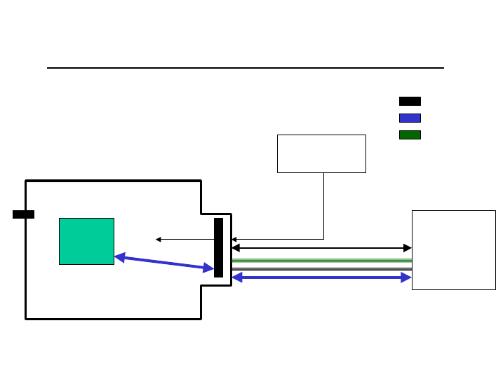
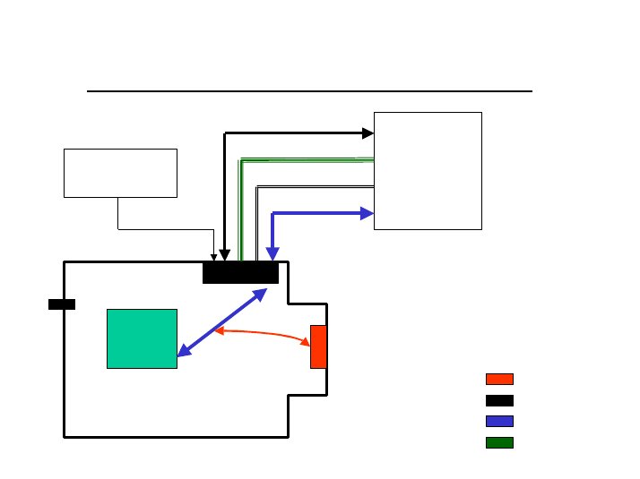
3. Pin description & main Functionality
3.1 Standard model & Slim model
The available functionality in these models are the follow:
Data & Voice (D10 Replacement & Slim) - Connections
D15
Main
Process.
Uart #1
RS232 port
User logic
Power supplies
Main PWR
Audio
Data port
EXT_SIM
DSC
General
Data purposes
DSC bus
3.1.1 Function available in the user connector – 36 pin ZIF
• VCC input. 3.0 to 6Vdc
• Full RS232 - 9 pins. TXD, RXD, RTS,CTS,DSR,DTR,DCD,RI
at 5V levels.
• External SIM connections. SIM Clock, SIM reset, SIM I/O,
SIM VCC,SIM PD
• DSC bus. DSC_EN, Downlink, Uplink –
Motorola proprietary us.
• Audio In/Out. Audio out and On/Off in the same
pin, audio in Signal and analog
ground.
• Man_Test line. Used to detect standard Motorola
accessories.
• TS line (mobport). Used to turn on the radio.
• TX_EN line. This line is an indication when
the radio is transmitting.
Note:
1. The Audio Out line is used to send out the detected audio
and as a toggle On/Off pin.
APPLICANT: MOTOROLA, INC. FCC ID: IHDT6AC1
Exhibit 8
10
2. The TS line is used to turn On the units by any transaction
from Low to high in this pin.
3.1.2 Connector pin out
Pin # Function Pin # Function
1 TX_EN 19 SIM I/O
2 N.U. 20 SIM CLK
3 N.U. 21 TS
4 TXD 22 DSC_EN
5 RXD 23 Down Link
6 DTR 24 Up Link
7 DCD 25 Analog Ground
8 RTS 26 Ground
9 CTS 27 Ground
10 DSR 28 Ground
11 RI 29 Ground
12 Manual_Test 30 VCC
13 Audio In 31 VCC
14 On/Off + Audio Out 32 VCC
15 N.U. 33 VCC
16 SIM _PD 34 NU
17 SIM _VCC 35 NU
18 SIM_Reset 36 NU
APPLICANT: MOTOROLA, INC. FCC ID: IHDT6AC1
Exhibit 8
11
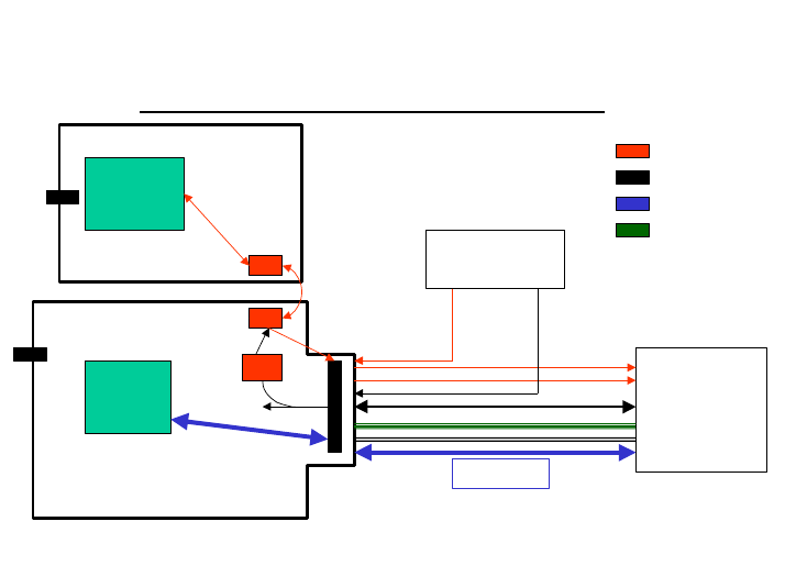
3.2 D15 with GPS
The available functionality in this models are the follow:
Data & Voice + GPS model - Connections
GPS (M12)
D15
Main
Process.
GPS
Process.
Uart #1
RS232 port
User logic
Power supplies
GPS Ant PWR
1PPS
RX Diff
Main PWR
Audio
Data port
EXT_SIM
DSC
GPS purposes
General
Data purposes
DSC bus
Reg
3V
3.2.1 Function available in the user connector – 36 pin ZIF
• VCC input. 3.0 to 6Vdc
• Full RS232 - 9 pins. TXD, RXD, RTS,CTS,DSR,DTR,DCD,RI
at 5V levels.
• External SIM connections. SIM Clock, SIM reset, SIM I/O,
SIM VCC,SIM PD
• DSC bus. DSC_EN, Downlink, Uplink –
Motorola proprietary us.
• Audio In/Out. Audio out and On/Off in the same
pin, audio in Signal and analog
ground.
• Man_Test line. Used to detect standard Motorola
accessories.
• TS line (mobport). Used to turn on the radio.
• TX_EN line. This line is an indication when
the radio is transmitting.
• GPS TXD & RXD in 3V levels, 1PPS,
APPLICANT: MOTOROLA, INC. FCC ID: IHDT6AC1
Exhibit 8
12
RTCM, Antenna power
Note:
1. The Audio Out line is used to send out the detected audio
and as a toggle On/Off pin.
2. The TS line is used to turn On the units by any transaction
from Low to high in this pin.
3. The GPS is mounted on top of theD15 and receive power from
the D15 but it is a stand-alone unit. The GPS is working from
3V and the RXD/TXD lines are working in 3V levels as well. The
GPS receiver used is M12 (Motorola).
3.2.2 Connector pin out
Pin # Function Pin # Function
1 TX_EN 19 SIM I/O
2 GPS RXD (out) 20 SIM CLK
3 GPS TXD (in) 21 TS
4 TXD 22 DSC_EN
5 RXD 23 Down Link
6 DTR 24 Up Link
7 DCD 25 Analog Ground
8 RTS 26 Ground
9 CTS 27 Ground
10 DSR 28 Ground
11 RI 29 Ground
12 Manual_Test 30 VCC
13 Audio In 31 VCC
14 On/Off + Audio Out 32 VCC
15 N.U. 33 VCC
16 SIM _PD 34 GPS Antenna Voltage 3/5 Vdc
17 SIM _VCC 35 RX for diff. GPS RTCM
18 SIM_Reset 36 GPS 1pps
APPLICANT: MOTOROLA, INC. FCC ID: IHDT6AC1
Exhibit 8
13
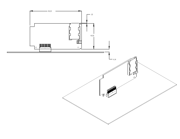
3.3 D15 in DIN Models (Vertical & Horizontal)
The available functionality in this models are the follow:
Data & Voice in DIN configuration- Connections
D15
White
Cap Uart #1
User logic
Power supplies
Main PWR
Audio
Data port
EXT_SIM
DSC
General
Data purposes
DSC bus
IRDA
IRDA (future feature)
3.3.1 Function available in the user connector –
28 R/A Male header (vertical model)
28 pin Female sockets, receptacle (Horizontal model)
• VCC input. 3.0 to 6Vdc
• Full RS232 - 9 pins. TXD,RXD,RTS,CTS,DSR,DTR,DCD,RI
at 5V levels.
• External SIM connections. SIM Clock, SIM reset, SIM I/O,
SIM VCC,SIM PD
• DSC bus. DSC_EN, Downlink, Uplink –
Motorola proprietary us.
• Audio In/Out. Audio out and On/Off in the same
pin, audio in Signal and analog
ground.
• Man_Test line. Used to detect standard Motorola
accessories.
• TS line (mobport). Used to turn on the radio.
• TX_EN line. This line is an indication when
the radio is transmitting.

APPLICANT: MOTOROLA, INC. FCC ID: IHDT6AC1
Exhibit 8
14
3.3.2 Connector pin out
Pin # Function Pin # Function
1. EXT. B+ (3.5 to 6V) 15. NU
2. EXT. B+ (3.5 to 6V) 16. TX_EN
3. SIM I/O 17. Analog GND
4. *SIM_RST 18. Audio Out+ On/Off
5. SIM VCC (3/5 Volt) 19. Audio In (Mic)
6. SIM PD 20. DSC_EN
7. DTR 21. DSR
8. TS 22. Down Link
9. Manual Test 23. Up Link
10. IRDA / RS232 Select 24. SIM_CLK
11. GND 25. TXD_U1
12. GND 26. RXD_U1
13. RI 27. CTS
14. DCD 28. RTS
Note:
1. The Audio Out line is used to send out the detected audio
and as a toggle On/Off pin.
2. The TS line is used to turn On the units by any transaction
from Low to high in this pin.
4. Modes of Operation
4.1 Turn On/Off the unit.
The D15 is powered from a single power supply in the range of
3.0 to 6.0 Vdc.
The unit will not power up automatically by connecting the
power and there are two ways to turn the unit On.
4.1.1 Turn On/Off the unit using the ON/OFF pin.
The On/Off pin (pin no’ 14 at the ZIF connector & pin no’ 18
at the DIN connector) is used as a toggel input to turn On and
Off the unit. Any drop to ground in this pin will change the
status.
To verify that the unit is On or Off you have to check the
DSC_EN line, If it is high the unit is On If it is low the
unit is Off.
APPLICANT: MOTOROLA, INC. FCC ID: IHDT6AC1
Exhibit 8
15
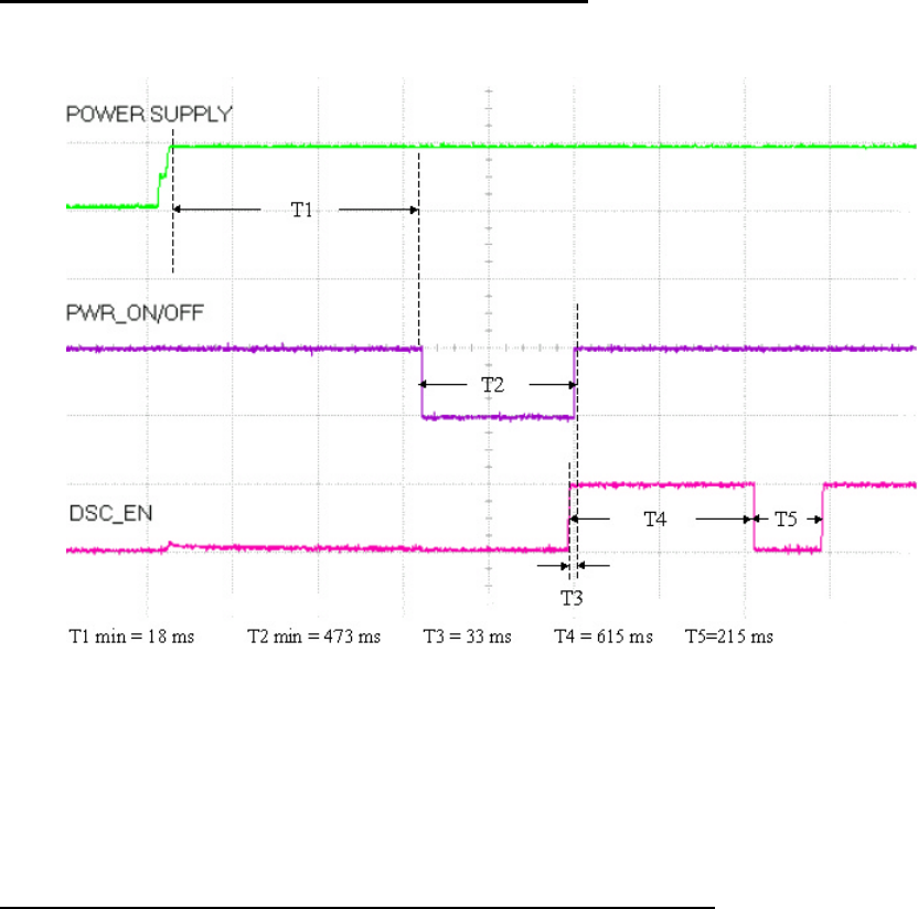
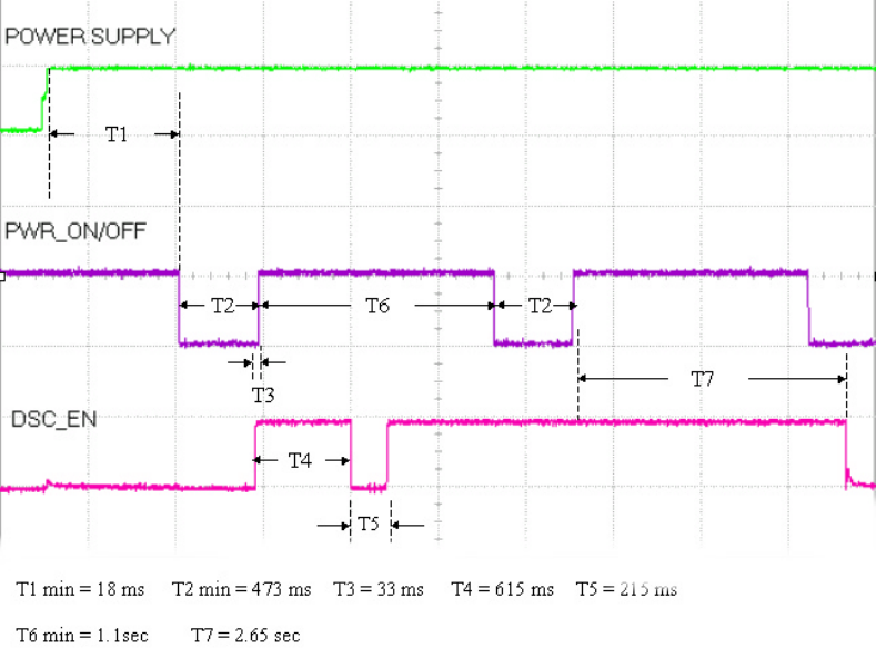
The timming for this process are the follow:
Turn On the unit using the ON/OFF pin
Turn On and Off the unit using the ON/OFF pin
APPLICANT: MOTOROLA, INC. FCC ID: IHDT6AC1
Exhibit 8
16
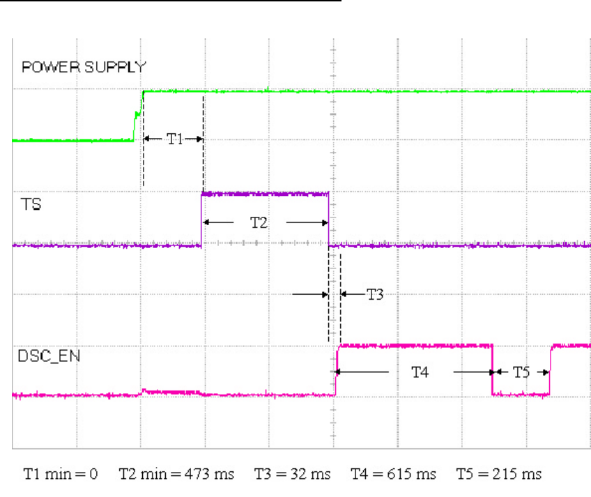
4.1.2 Turn On the unit using the TS pin.
The main used of the TS line is for units connected to a
mobile device in witch the current consuption is not the main
consern.
The TS line is used to turn On the unit. This line can’t turn
Off the unit.
When this line is rised up it will turn On the unit.
This line is used for example to turn On the unit when power
is connected to the unit. (Like Ignition line in a car kit).
Be aware that if you keep this line high all the time the unit
will not go to Sleep mode (current save mode), So it is
recommended to turn On the unit and than drop this line.
APPLICANT: MOTOROLA, INC. FCC ID: IHDT6AC1
Exhibit 8
17
Turn On the unit using the TS line
APPLICANT: MOTOROLA, INC. FCC ID: IHDT6AC1
Exhibit 8
18
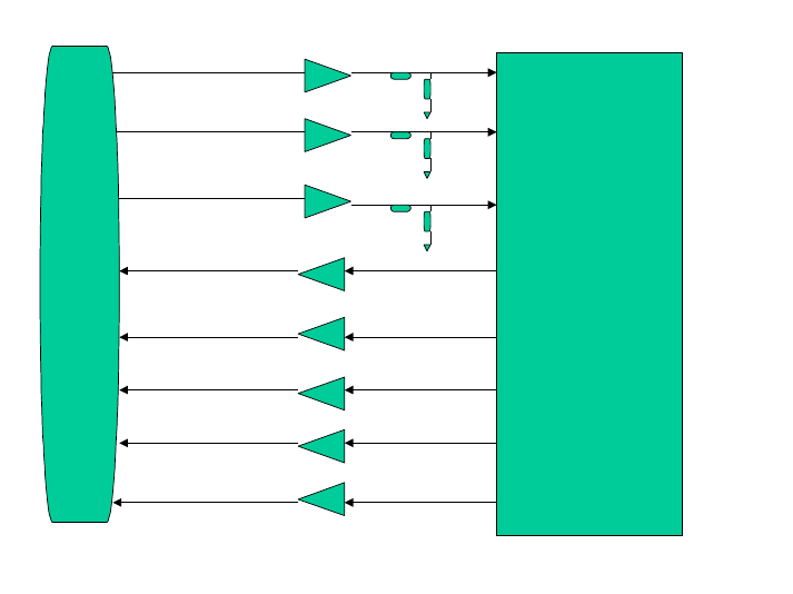
4.2 Data connectivity.
To clarify the Data connectivity and the direction of the
signal see the follow diagram:
All the signals in the user connector are 0 to 5V.
When the control lines (RTS, DTR, DCD, CTS, DSR, RI) active is
low (0V) and unactive is high (5V).
4
6
8
5
7
9
10
11
User connector
(ZIF 36 pin)
EXT_TXD
EXT_DTR
EXT_RTS
EXT_RXD
EXT_DCD
EXT_CTS
EXT_DSR
EXT_RI
TXD
DTR
RTS
RXD
DCD
CTS
DSR
RI
D15
processor

APPLICANT: MOTOROLA, INC. FCC ID: IHDT6AC1
Exhibit 8
19
25
7
28
26
14
27
21
13
User connector
28 pin DIN
EXT_TXD
EXT_DTR
EXT_RTS
EXT_RXD
EXT_DCD
EXT_CTS
EXT_DSR
EXT_RI
TXD
DTR
RTS
RXD
DCD
CTS
DSR
RI
D15
processor
There are two modes to use the Data port:
- SoftGSM mode. This mode is for computer aplication in witch
an application SW “SoftGSM” is use. This alowed the D15 to
work with V42.bis (data compression), transfer fax and
SMS.
- RS232 full flow control. This is the defaul setting for the
D15. In this mode we can transfer data and SMS using a full
flow control (HW flow control), Xon/Xoff or non flow
control.
There is now FAX capability in this mode.
APPLICANT: MOTOROLA, INC. FCC ID: IHDT6AC1
Exhibit 8
20
4.2.1 Using the SoftGSM.
4.2.1.1 SoftGSM Selection
The selection of SoftGSM is done by Hardware in the user
application.
In order to switch to this mode the user need to connect
pulldown resistors of 22Kohm in the Downlink line (pin no’23
in the zif connector or pin no’22 in the 28 pin) and the
DCS_EN line (pin no’22 in the zif connector or pin no’20 in
the 28 pin).
In this mode the necessary lines are: TXD, RXD.
An example for the circuitry to add the pulldown resistor can
be seen in Pharagraph ??? EV_board design.
4.2.1.2 File / Fax / SMS transfer in SoftGSM mode.
To Transfer a file in softGsm you need to:
1. connect the RX/TX lines of the D15 a a comm port of the
computer. .(the levels should be converted to RS232 or use
a EV board or equivqlent).
2. Run the SoftGsm Application in the computer.
3. The SoftGsm program will open a phone tools application.
4. Use the phone application to send/Receive file/Fax/SMS .
APPLICANT: MOTOROLA, INC. FCC ID: IHDT6AC1
Exhibit 8
21
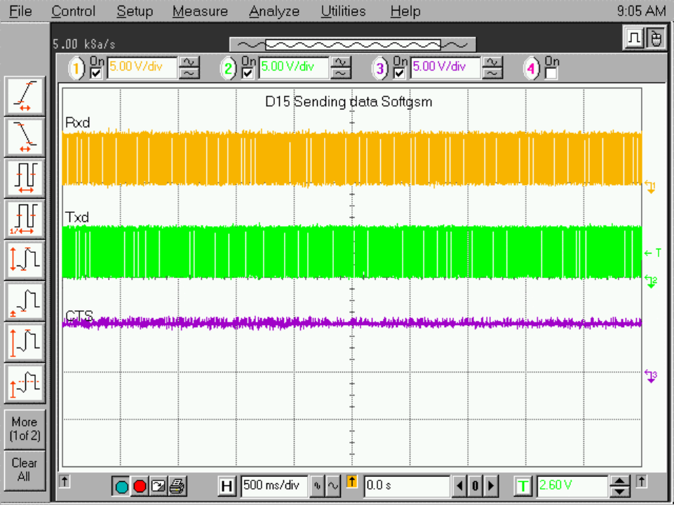
The activity of the required lines and timming for file
transfer using SoftGsm can be seen in the following plot:
Sending / Receiving files in SoftGsm
APPLICANT: MOTOROLA, INC. FCC ID: IHDT6AC1
Exhibit 8
22
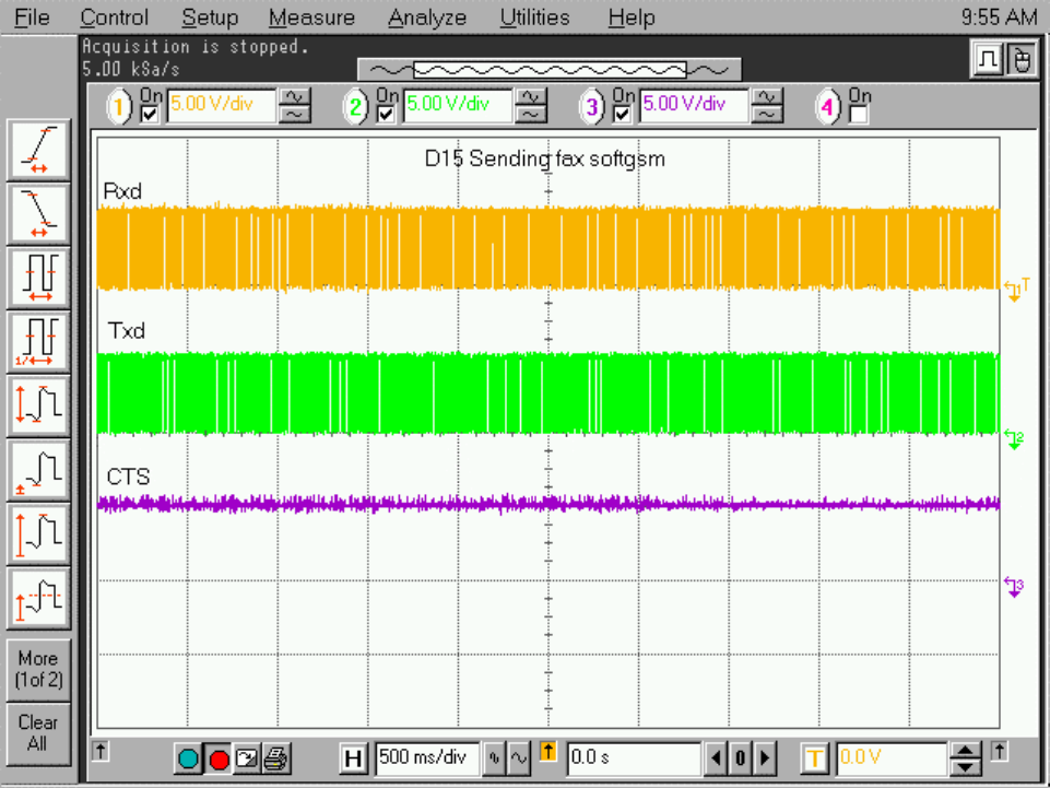
The activity of the required lines and timming for Fax
transfer using SoftGsm can be seen in the following plot:
Sending / Receiving Fax in SoftGsm
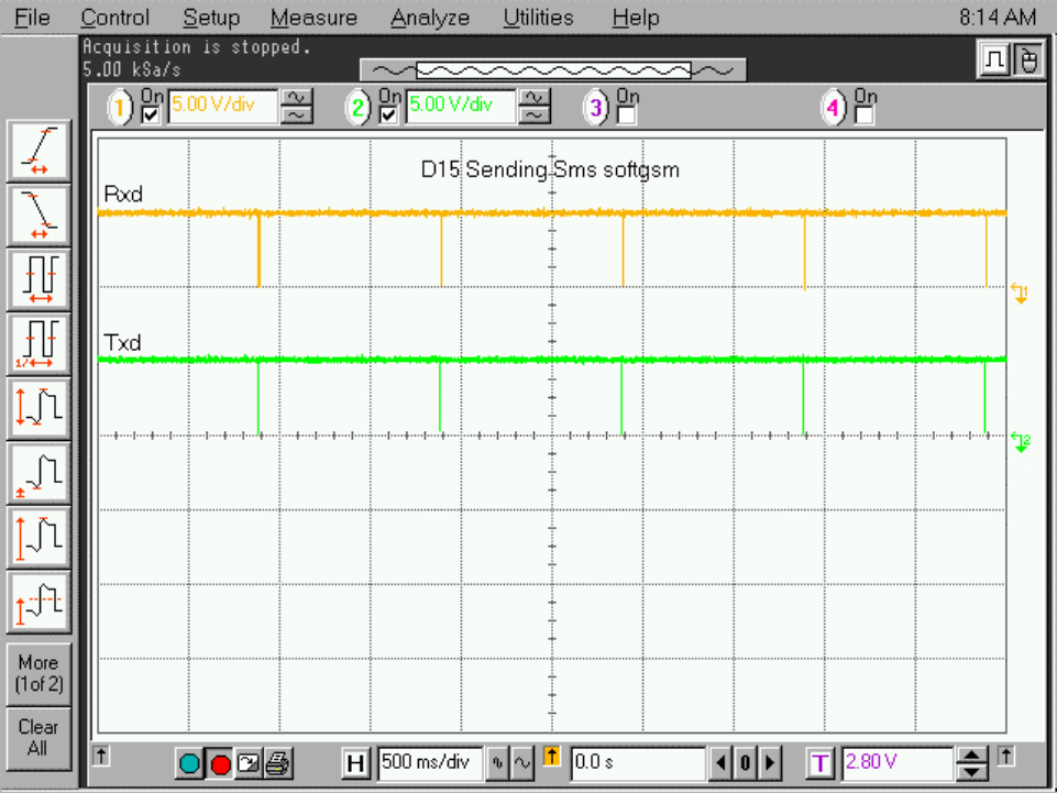
The activity of the required lines and timming for SMS
transfer using SoftGsm can be seen in the following plot:
APPLICANT: MOTOROLA, INC. FCC ID: IHDT6AC1
Exhibit 8
23
Sending / Receiving SMS PDU mode in SoftGsm
4.2.1.4 Sending / Receiving SMS block mode.
TBD
APPLICANT: MOTOROLA, INC. FCC ID: IHDT6AC1
Exhibit 8
24
4.2.2 Using RS232.
4.2.2.1 RS232 Selection
The RS232 is the default setting in the D15 and no HW
selection is needed.
The RS232 can use 3 different modes of setting to the DTE
device:
HW (Hardware) flow control – all RS232 lines are used (DTR,
DSR, RTS, CTS, TXD, RXD, DCD, RI, GND).
None flow control – DTR, DSR, TXD, RXD, DCD, RI, GND are
required.
Xon / Xoff flow control – DTR, DSR, TXD, RXD, DCD, RI, GND are
required.
4.2.2.2 work with RS232 with "sleep mode"
If the D15 will have no accessories and the unit is camped the
D15 will go to a "sleep mode" (current save mode).
During this period of time the RS232 is not responding to any
command from the DTE device(Uart is not activated).In order to
make the unit to wake up when the DTE will like to communicate
with the radio the user have two options:
1. Activate the RTS During all the DTE/DCE dialog. (Internaly
the TS line will be activated). After the communication
disable the RTS in order to go back to sleep mode.
2. Activate the TS During all the DTE/DCE dialog. After the
communication disable the TS in order to go back to sleep
mode.
APPLICANT: MOTOROLA, INC. FCC ID: IHDT6AC1
Exhibit 8
25
4.2.2.3 File transfer in RS232 mode.
To Transfer a file in RS232 you need to:
1. connect the relevant lines depend on the mode to a comm
port of the computer.(the levels should be converted to
RS232 or use a EV board or equivqlent).
2. Run Hyper terminal application or equivalent in the
computer. (in the final application it will be the user
program).
3. Select the flow control / Comm and baud rate.
4. Select the activity send/Receive file/Fax/SMS .
The diling process / signalizationn can be seen in the
following diagrams:
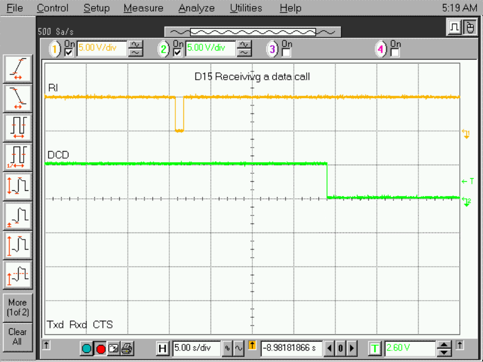
Receiving a ring.
APPLICANT: MOTOROLA, INC. FCC ID: IHDT6AC1
Exhibit 8
26
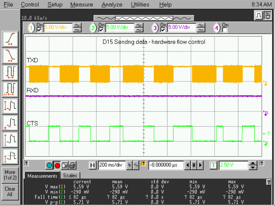
The activity of the required lines and timming for file
transfer using RS232 HW flow control can be seen in the
following plot:
Sending a file in HW flow control.
APPLICANT: MOTOROLA, INC. FCC ID: IHDT6AC1
Exhibit 8
27
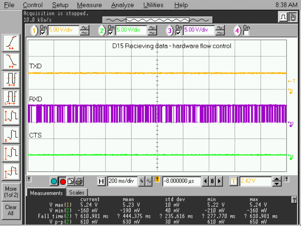
Receiving a file in HW flow control
APPLICANT: MOTOROLA, INC. FCC ID: IHDT6AC1
Exhibit 8
28
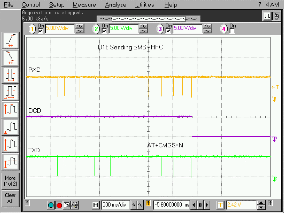
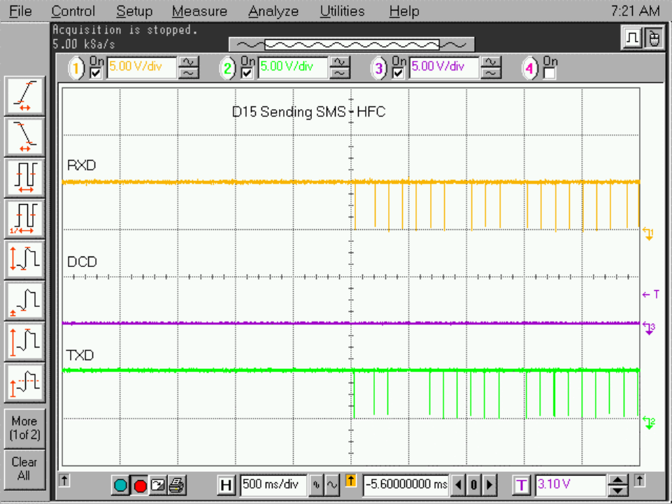
Sending a SMS in PDU mode – HW flow control.
Step 1 – preparing the data to be sent:
APPLICANT: MOTOROLA, INC. FCC ID: IHDT6AC1
Exhibit 8
29
Step 2: inserting the SMS message:
APPLICANT: MOTOROLA, INC. FCC ID: IHDT6AC1
Exhibit 8
30
Step 3: Sending the SMS:
APPLICANT: MOTOROLA, INC. FCC ID: IHDT6AC1
Exhibit 8
31
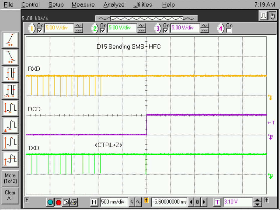
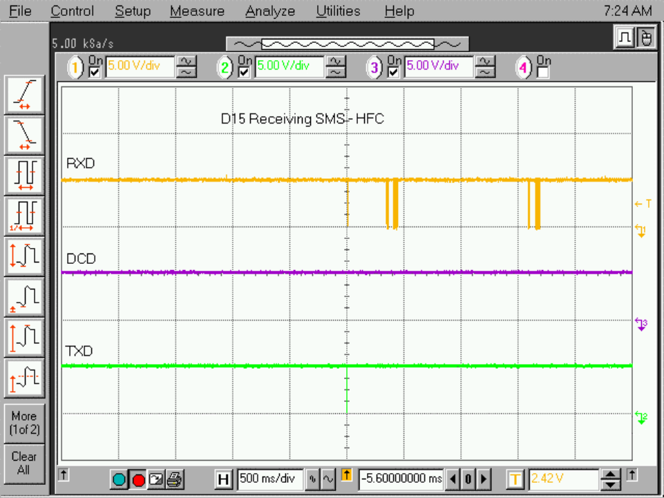
Receiving a SMS in PDU mode – HW flow control.
APPLICANT: MOTOROLA, INC. FCC ID: IHDT6AC1
Exhibit 8
32
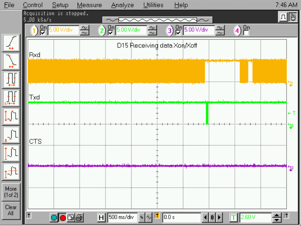
4.1.2.1 Transfer files using Xon/Xoff setting.
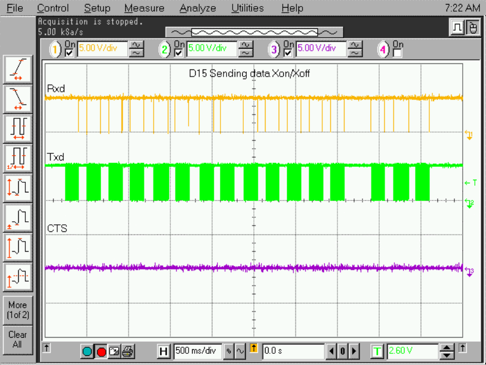
Sending a file n Xon / Xoff
APPLICANT: MOTOROLA, INC. FCC ID: IHDT6AC1
Exhibit 8
33
Receiving a file in Xon / Xoff
APPLICANT: MOTOROLA, INC. FCC ID: IHDT6AC1
Exhibit 8
34
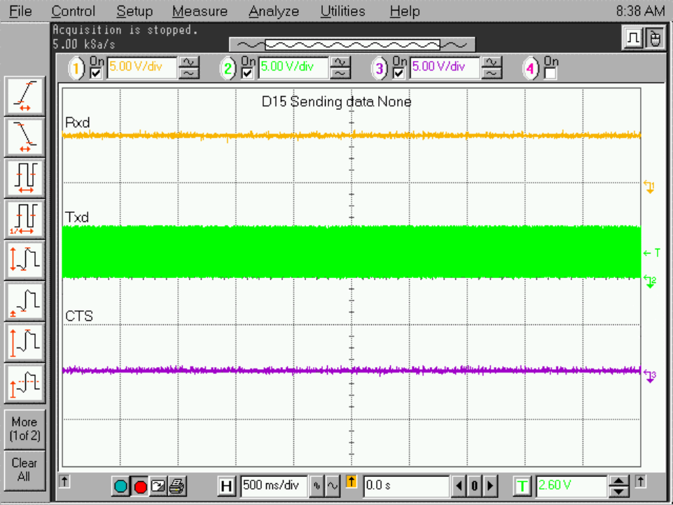
4.1.2.2 Transfer files using none setting.
Sendng a file in none mode
APPLICANT: MOTOROLA, INC. FCC ID: IHDT6AC1
Exhibit 8
35
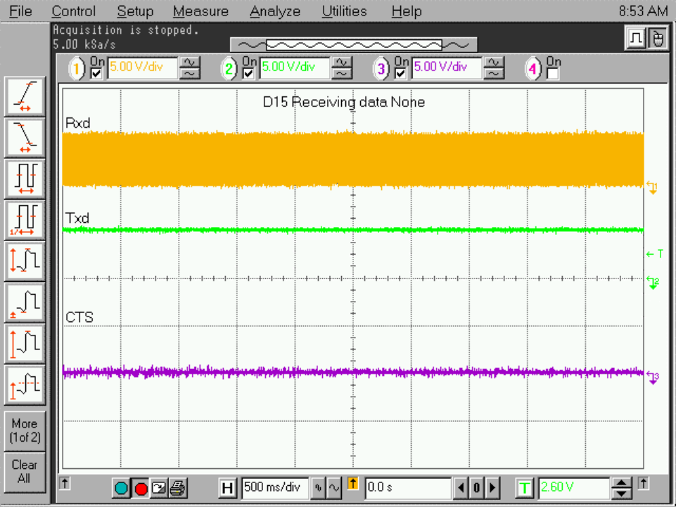
Receiving a file in none mode
4.1.2.2 Sending/ Receiving SMS block mode.
TBD
APPLICANT: MOTOROLA, INC. FCC ID: IHDT6AC1
Exhibit 8
36
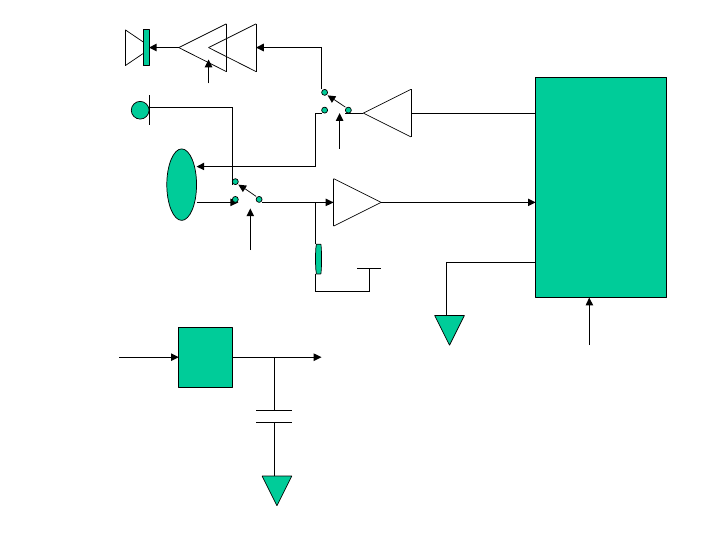
4.3 Voice connectivity.
The D15 is an OEM Data & Voice module.
The voice connectivity can be done in two main channels –
analoge voice, Digital voice.
4.3.1 Digital voice:
The Digital voice is done using the Motorola DCS bus.
This bus is an Motorola Propriretry bus and details can be
received after an agreement.
General connections:
User
DSC
Drivers +
Audio Drivers
D15
DCS_EN
DownLink
Uplink
In case that the D15 is connected to a standard Motorola Car
Kit the TS line should be connected to VCC in order to turn On
the unit using the Ignition line.
APPLICANT: MOTOROLA, INC. FCC ID: IHDT6AC1
Exhibit 8
37
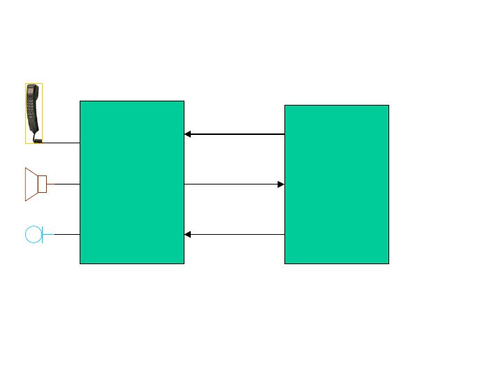
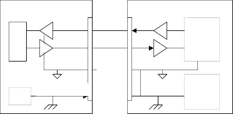
4.3.2 Analog Audio.
The D15 is driving out the analog audio detected by the radio.
The D15 is not including any audio drivers. The user have to
include the audio drivers in is application.
An example for audio drivers can be seen in the EV board
appendix ??.
The D15 can provide the analog audio in two ways:
- Analog audio to by drived to an Headset – Default.
- Analog audio with Echo canceller activated – for Hands free
applications.
When an Headset is used in the user application than audio
drivers for the headset are needed.
When an external Speaker and Microphone are used drivers for
them are required and activation of Echo canceller in the D15
DSP is required.
To activate the Echo canceller you need to type an AT command
in the Data port.
ATs96=1 will activate the Echo canceller.
ATS96=0 will disable the Echo canceller.
The block diagram for the required drivers are shown below,
But detailled example of drivers design you can see the
Evaluation board design, Pharagraph ???.
APPLICANT: MOTOROLA, INC. FCC ID: IHDT6AC1
Exhibit 8
38
Audio out
Audio In
D15
Headset
A1
A2
Analog GND
REF
VCC Vref
SPKR
MIC
Hands Free
Selection via
ATS96 command.
Hands Free
Selection
Hands Free
Selection
(for Audio amp)
VCC
12V
The requirements from the drivers and audio devices are the
follow:
Microphone impedance: Typical 700Ω
S/N ratio Minimum 35dB
Gain from headset to D15 (A2) 45 – 49 dB
Frequency response -11 to +1 dB 300 to 3400Hz.
(including microphone)
D15 input impedance 10KΩ
TX Distortion Maximum 5%.
Speakerphone Load 25 to 39W.
S/N Minimum 35dB
Gain from D15 to Headset (A1) -13 to –9 dB
Frequency response -10 to +1 dB 300 to 3400Hz.
(including SPKR)
D15 output impedance <1KΩ
Distortion Maximum 5%.

APPLICANT: MOTOROLA, INC. FCC ID: IHDT6AC1
Exhibit 8
39
The Audio route for the different devices is descrived in the
following table:
Configuration Setup and aAudio Routing in D15
1. HF Refer to External Speaker & Microphone connected.
2. DHFA refers to External Car kit.
3. Correct setup are in bold letters.
Configuration Setup Audio Route to…
Off hook handset
(overrides all other conditions) Handset.
On hook handset, or absence of handset:
- HF + HF was selected by AT command
- HF + HF was not selected by AT command
- DHFA
- Headset + HF was selected by AT command
- Headset + HF was not selected by AT command
-
- HF external Speaker with Echo cancelling
- HF External Speaker,W/O Echo cancelling
- DHFA Speaker
- Headset with Echo Cancelling
- Headset W/O Echo Cancelling

APPLICANT: MOTOROLA, INC. FCC ID: IHDT6AC1
Exhibit 8
40
5. Design Consideration
5.1 Power supply considerations. Current requirements in each
mode.
5.2 Audio considerations.to refer to EV board chepter in
appendix.Car Kit connectionsl.
5.3 Data port considerations & Levels.
5.4 SIM card considarations.
5.5 ESD considerations.
5.6 Antenna
5.7 Software
5.8 Mechanical
5.1 Power supply consideration.
5.1.1 Power Supply losses.
The D15 is specified to operate from 3.0V to 6.0V. In order to
be able to work in the lowest battery values it is important
to verify the losses in the power supplies lines, Flat cable
and in the user PCB.
The D15 is a GSM phone that transmits in pulses of about 0.5mS
any 4mS. The Peak current is about 1.5A.
The VCC line will drop down in the TX periods:
In order to minimize the ∆ it is recommended to use a short
Flat cable as possible and to put a 1000uF capacitor (or
maximum possible) in the D15 VCC input.
5.1.2 Current consumption in D15:
In order to design the power supply correctly you need to take
in account the current consumption of the D15 in the different
TX
TX
TX
Transmit
Periods
VCC

APPLICANT: MOTOROLA, INC. FCC ID: IHDT6AC1
Exhibit 8
41
modes.
Mode Current consumption
D15 with no
accessory when no
call is in process
<11mA Typical 10mA.
D15 with no
accessory but TS or
RTS are ON
< 50mA.
D15 during
searching time <180mA typical
average 80mA.
D15 with DSC bus
accessory(like
Handset) when no
call is in process
Typical 40 mA.
D15 during a call
in maximum power
level
<1.5A Peak, Average
300mA.
D15 during a call
in GSM power level
#10 (for Example)
<0.7A Peak, Average
175mA
APPLICANT: MOTOROLA, INC. FCC ID: IHDT6AC1
Exhibit 8
42
5.1.3 How / When to make the unit to wakeup.
If the D15 will have no accessories and the unit is camped the
D15 will go to a "sleep mode" (current save mode).
During this period of time the RS232 is not responding to any
command from the DTE device.In order to make the unit to wake
up when the DTE will like to communicate with the radio the
user have two options:
1. Activate the RTS During all the DTE/DCE dialog. (Internaly
the TS line will be activated). After the communication
disable the RTS in order to go back to sleep mode.
2. Activate the TS During all the DTE/DCE dialog. After the
communication disable the TS in order to go back to sleep
mode.
Note: If the RTS or TS line will be active all the time the
unit will not switch to Sleep mode and the avarage current
consumption without a call will be arround 50mA.
Timing diagrams should be added. - TBD
5.2 Audio circuits consideration.
The D15 is able to make a voice call as well as Data calls.
In voice calls the audio can be routed in a few channels:
Digital audio chanel - Audio is sent via the DSC bus.
Analog audio channel - Drived externaly to audio devices.
Analog audio channel in Hands free mode - D15 sens the
audio out with the Echo canceling ON in the DSP, External
drivers are required.
The Selection between each one of the channels can be done
according to the table XX in paragraph 4.3.2.
APPLICANT: MOTOROLA, INC. FCC ID: IHDT6AC1
Exhibit 8
43
5.2.1 Digital audio.
In case of digital audio channel a DCS drives is in used. The
consideration that should be taken in this case is to be aware
of the present of the hook switch. The hook switch will
destinguish if the handset is In/Out of use.
There are two DSC bus accessories for audio defined for the
D15:
External Handset.
DHFA - Car Kit for Hands Free.
5.2.2 Analog Audio without Handsfree.
The D15 will drive the audio out/in in order to allowed a
voice call. In order to connect an Headset it is needed to
amplified the speaker and microphone channels.
An example for these drivers can be seen in Apendix ?? EV
board.
Other point to be taken in consideration is the Buzz noise
existing in GSM phones due to the transmission rate (217Hz).In
order to minimize this noise the D15 have a separate ground
for the analog circuits.
Analog
Circuits
Logic
Circuits
PS
Digital Ground
Digital Ground
Analog
Ground
Customer side
D15
APPLICANT: MOTOROLA, INC. FCC ID: IHDT6AC1
Exhibit 8
44
The main problem causing the Buzz is drops in the Ground line
because the peak current during TX mode. In order to minimize
the Buzz the following acts should be done:
- Use short Flat cable.
- Connect the analog ground from the D15 to all the analog
circuits in the customer application without connecting them
to the power supply ground.
- all the capacitors to ground in the audio circuits should be
connected to the analog ground.
- Any reference voltage that may be used should have the
external capacitor connected to the analog ground.
5.2.3 Analog Audio with Handsfree
The audio In/Out from the D15 for analog Handsfree are the
same as for non Handsfree.All the consideration from Paragraph
5.2.2 are applicable for this mode too.
The additional consideration in this case is to switch the D15
DSP to Echo cancelling mode.
In oreder to switch to handsfree mode use the RS232 port by
sending a switch command.
ATS96=1 Echo canceller is activate. (Handsfree)
ATS96=0 Echo canceller is disabled. (headset - Default)
APPLICANT: MOTOROLA, INC. FCC ID: IHDT6AC1
Exhibit 8
45
5.3 Data port considerations.
5.3.1 Data levels.
The D15 data lines are operating in 0 to 5V logic. All the
In/Out signals are bufferd by an MC74VHCT244 buffer.
DTR, DSR, RTS, CTS, DCD lines are "1" (active) in 0V and "0"
(inactive) in 5V.
The signal treshoulds are:
Vih 2.0V min.
Vil 0.8V max.
Voh 4.4V min. @ 50uA or 3.8V min. @ 8mA.
Vol 0.1 max. @ 50uA or 0.44V @ 8mA.
5.3.2 Select the data mode:
The D15 can support two different modes of operation:
SoftGsm - For PC applications.
RS232 full flow control - General applications.
The RS232 is the default mode and no action is needed to
switch to this mode.
The SoftGsm require hardware connection to two lines.
Down link pin should be connected via 22KOhm to ground.
DSC_EN pin should be connected via 22KOhm to ground.
APPLICANT: MOTOROLA, INC. FCC ID: IHDT6AC1
Exhibit 8
46
5.4 SIM lines consideration.
The SIM card can be used in 3 different ways: Internaly in the
D15, Externaly by connecting a socket in the customer
application and remotly via the DCS bus.
In case of externaly connection the customer concern should be
for Full Type Approval that may require submittion for testing
in case that the SIM lines will be longer than 10cm.
This Paragraph should be completed.
5.5 ESD consideration - TBD
5.6 Antenna - To take from D10 manual.
5.7 Software - TBD
5.8 Mechanical - TBD
7. Appendix
7.1 Specifications
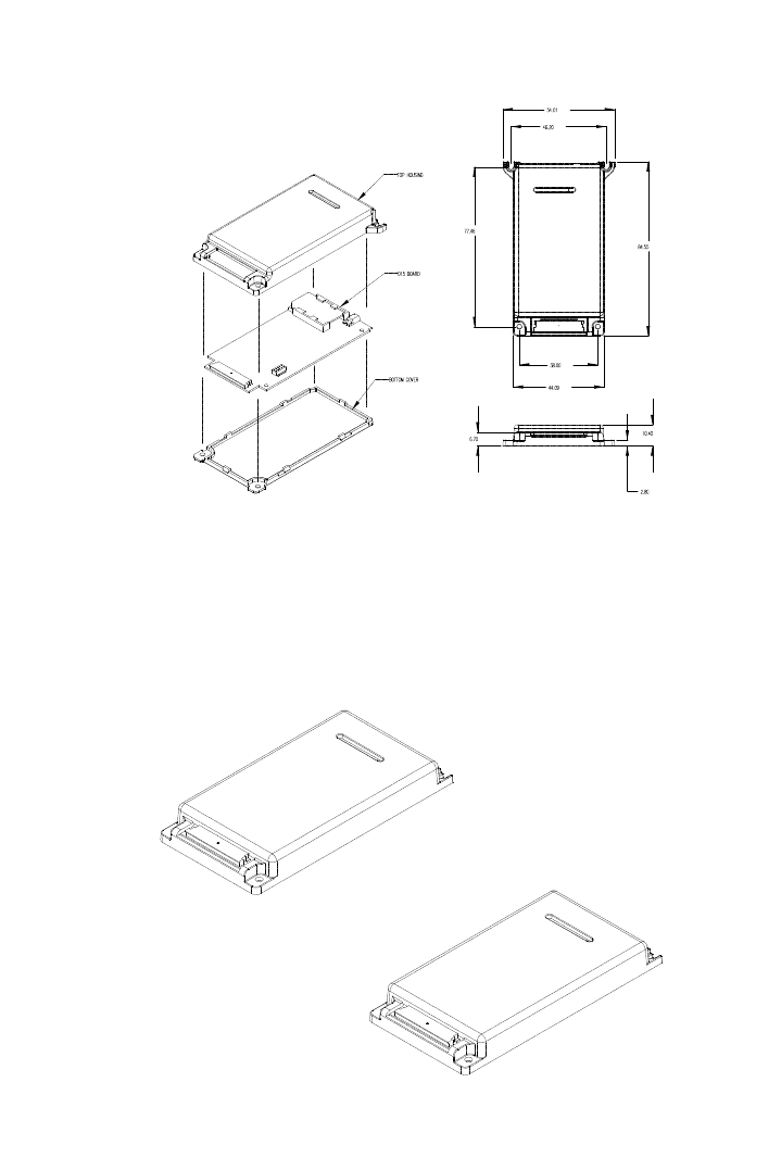
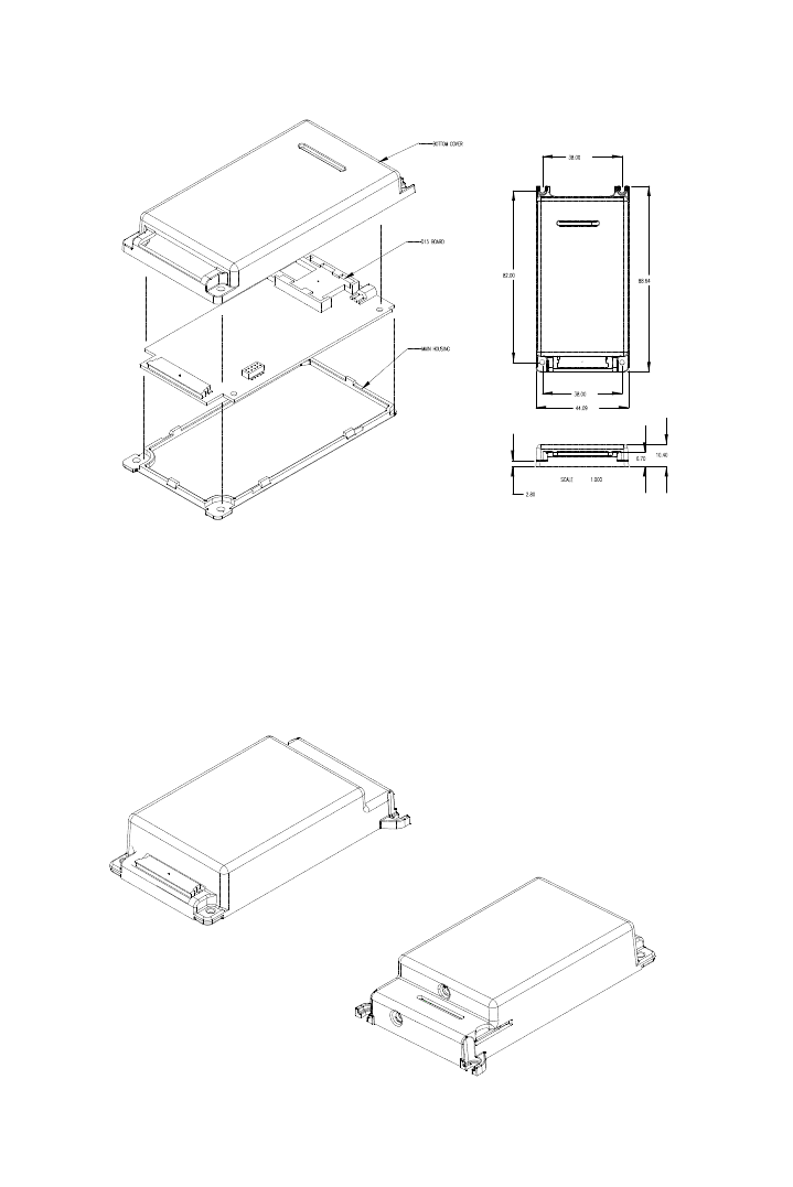
Physical
Form factor: PCMCIA type III, no PCMCIA connector
Size: d15 DV Standard: 53.92x85.61x10.4mm
(see drawings in this spec)
d15 DV Slim: 44.28x88.45x10.4mm
d15 DVG with GPS: 44.74x88.45x17.6mm
d15 DV DIN: 40x80.2x7.5 mm
Mounting: Four 2.43mm Ø holes provided on non DIN models
Weight: D15 DV Standard: 39g
D15 DV Slim: 35.5g
APPLICANT: MOTOROLA, INC. FCC ID: IHDT6AC1
Exhibit 8
47
D15 DVG with GPS: 49g
D15 DV DIN: 22g
Volume: D15 DV Standard: cc
D15 DV Slim: cc
D15 DVG with GPS: cc
D15 DV DIN: cc
Housing
material: Plastic housing PC/ABS
d15 DV Standard / Slim/
DVG: 36 pin ZIF socket @
0.5mm pitch
ELCO #04-6240-036-800
d15 DV Vertical Board
Only: 28 pin dual in line
Header @1.27 pitch
(SAMTEC # FTSH-114 -01-
L-DH)
Interface
connector:
d15 DV Horizontal Board
Only: 28 pin dual in line pin
socket @1.27 pitch
SAMTEC # CLP-114-02-L-D)
RF output
connector: MMCX Jack (female) 50Ω GSM and GPS Mating
connectors Plug (Male)
Coax Huber-Shuhner Johnson Components
RG178 11-MMCX-50-1-1 135-3302-001
RG316 11-MMCX-50-2-3 135-3403-001
Environmenta
l
Operational
temperature:
-30 to +60 degrees C
Storage
temperature:
-40 to +85 degrees C
Shock: 20 g’s with 11 millisecond duration, 20 impacts
in three mutually perpendicular planes
Vibration: IS-19: 1.5g acceleration, 5 to 500 Hz @ 0.1
octave/minute in three mutually perpendicular
planes
Performance
Operating
systems
GSM 900MHz, DCS 1800MHz, PCS 1900MHz.
Voltage:® 3.0 to 6V
Current: 10 mA Stand by
150uA off current
300mA avg. in call at power level 5
1.2 A peak @ 217 Hz at power level 5
Power out: GSM – Power levels #19 to 5, 5dBm to 33dBm per
ETSI.
DCS – Power levels # 15 to 0, 0dBm to 30 dBm per
APPLICANT: MOTOROLA, INC. FCC ID: IHDT6AC1
Exhibit 8
48
ETSI.
PCS – Power levels # 15 to 0, 0 dBm to 30 dBm per
FCC.
SIM Card
Reader:¬
Options: 1. Internal - chip SIM CR 3/5V SIM
2. External - Local interface 3/5 SIM
3. External - Remote interface (DSC
interface) 5V only
Interface: Options 1. 9 pin RS232 Serial Asynchronous
full flow control , 5V logic level
2. 4 pin RS232 Serial Asynchronous
using SoftGsm SW for PC applications, 5V logic
levels.
3. Motorola Proprietary DSC Bus
4. IRDA communication – In DIN models
only.
Host Protocol: AT commands including GSM 07.07 and GSM 07.05
(see Developers manual for specific AT commands
supported.
APPLICANT: MOTOROLA, INC. FCC ID: IHDT6AC1
Exhibit 8
49
Data: Transparent/Non transparent up to 14.400 bps.
- V.42 bis when using SoftGSM only.
PC FAX: Class 1,2 group 3 when using SoftGSM only
SMS: Send and receive (PDU and block mode per GSM
07.05)
Voice Call: Supported I/O with external H/SET
Audio: Analog – Full duplex I/O on interface connector
Digital – Motorola Proprietary DSC Bus
GPS: Independent GPS receiver on GPS model only
GPS (TXD, RXD, 1PPS, RTCM, Antenna Voltage) Functions are
available on the ZIF and DIN header/socket connector at 3V
logic levels.
1. 12 parallel channel
2. L1 1574,42 MHz
3. Code plus carrier tracking (carrier aided
tracking)
4. Positional accuracy: 100 meters 2dRMS with SA
as per DoD specifications, less than 25 meters
SEP without SA
Additional specifications available on request