Motorola Solutions 89FT7629 Access Point/CPE User Manual User Guide Part 5
Motorola Solutions, Inc. Access Point/CPE User Guide Part 5
Contents
- 1. User Guide Part 1
- 2. User Guide Part 2
- 3. User Guide Part 3
- 4. User Guide Part 4
- 5. User Guide Part 5
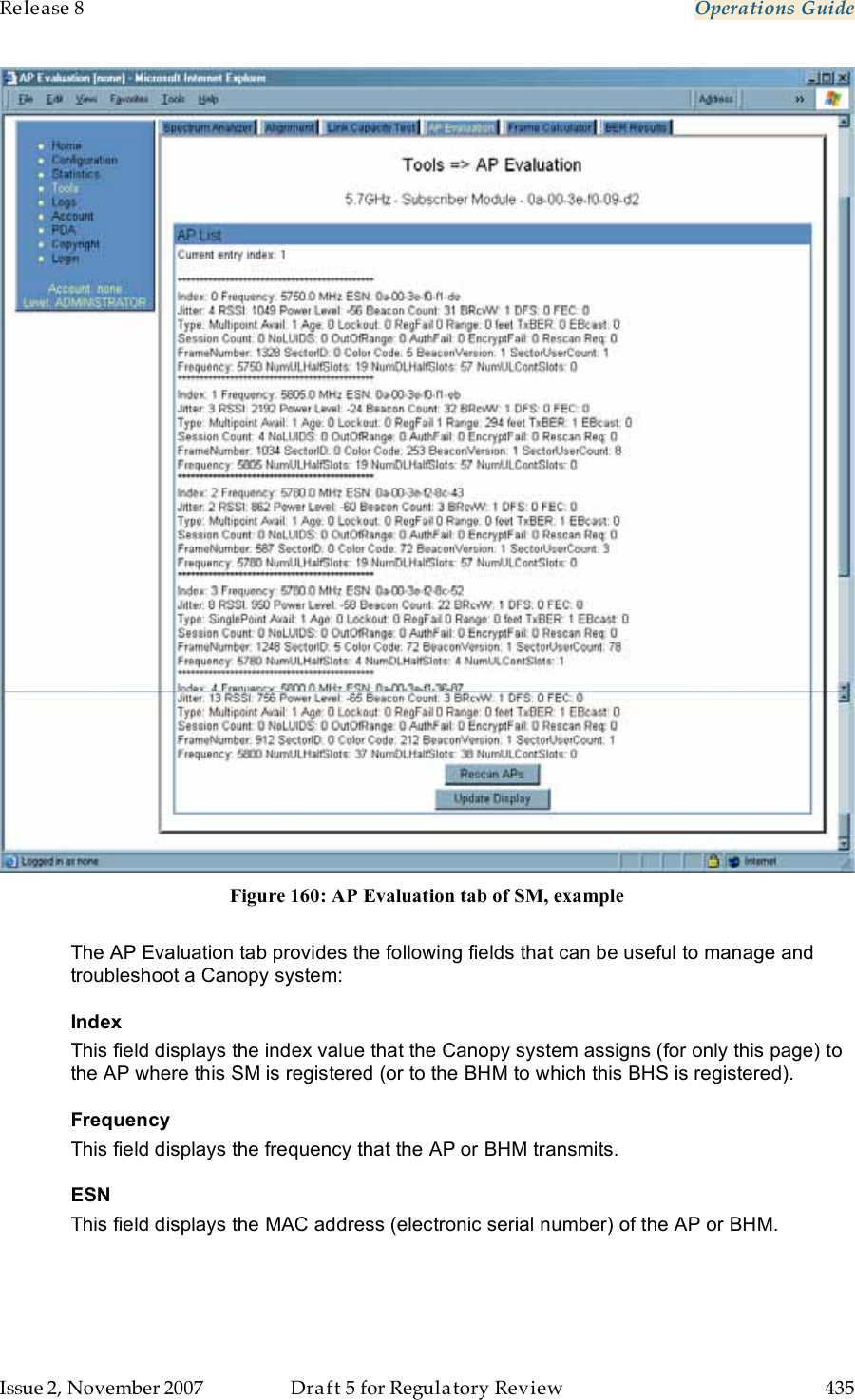
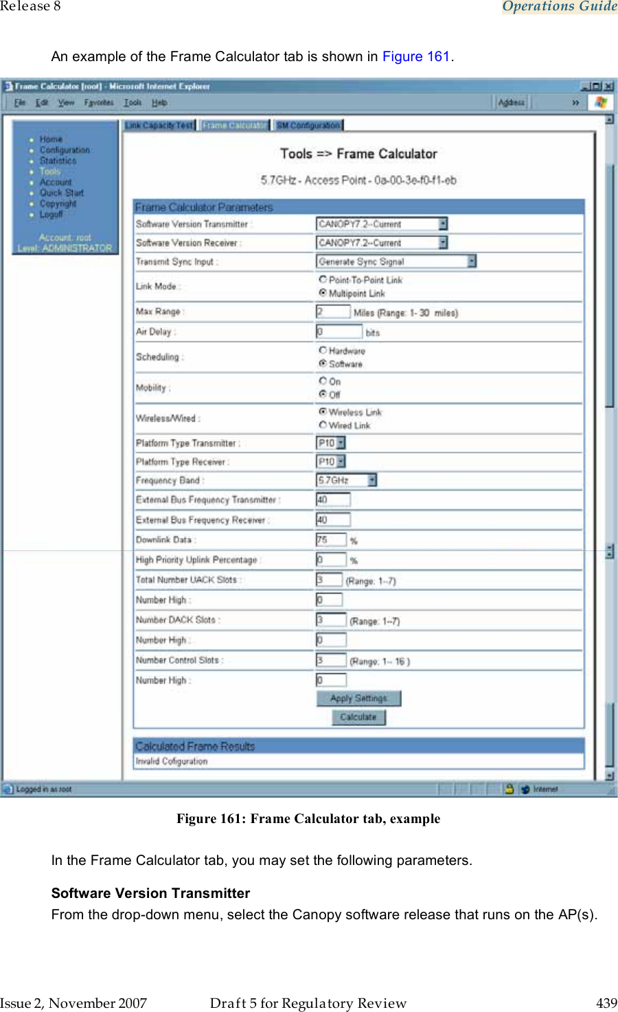
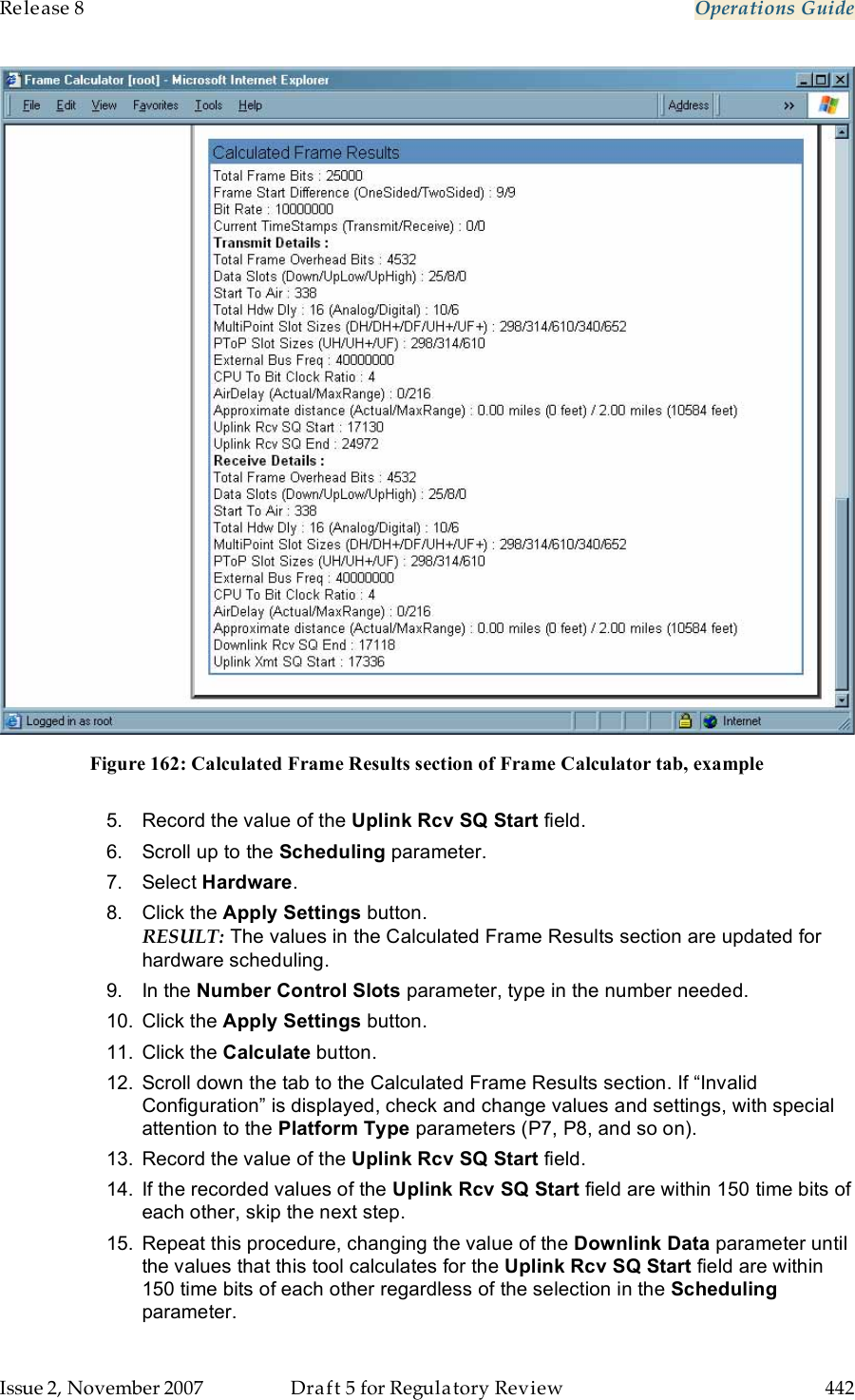
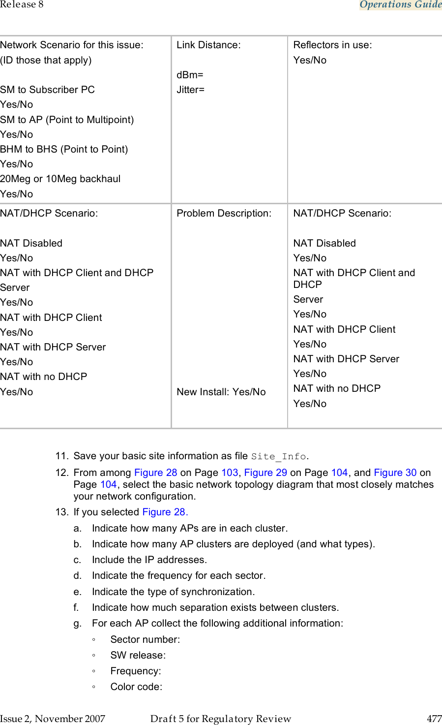
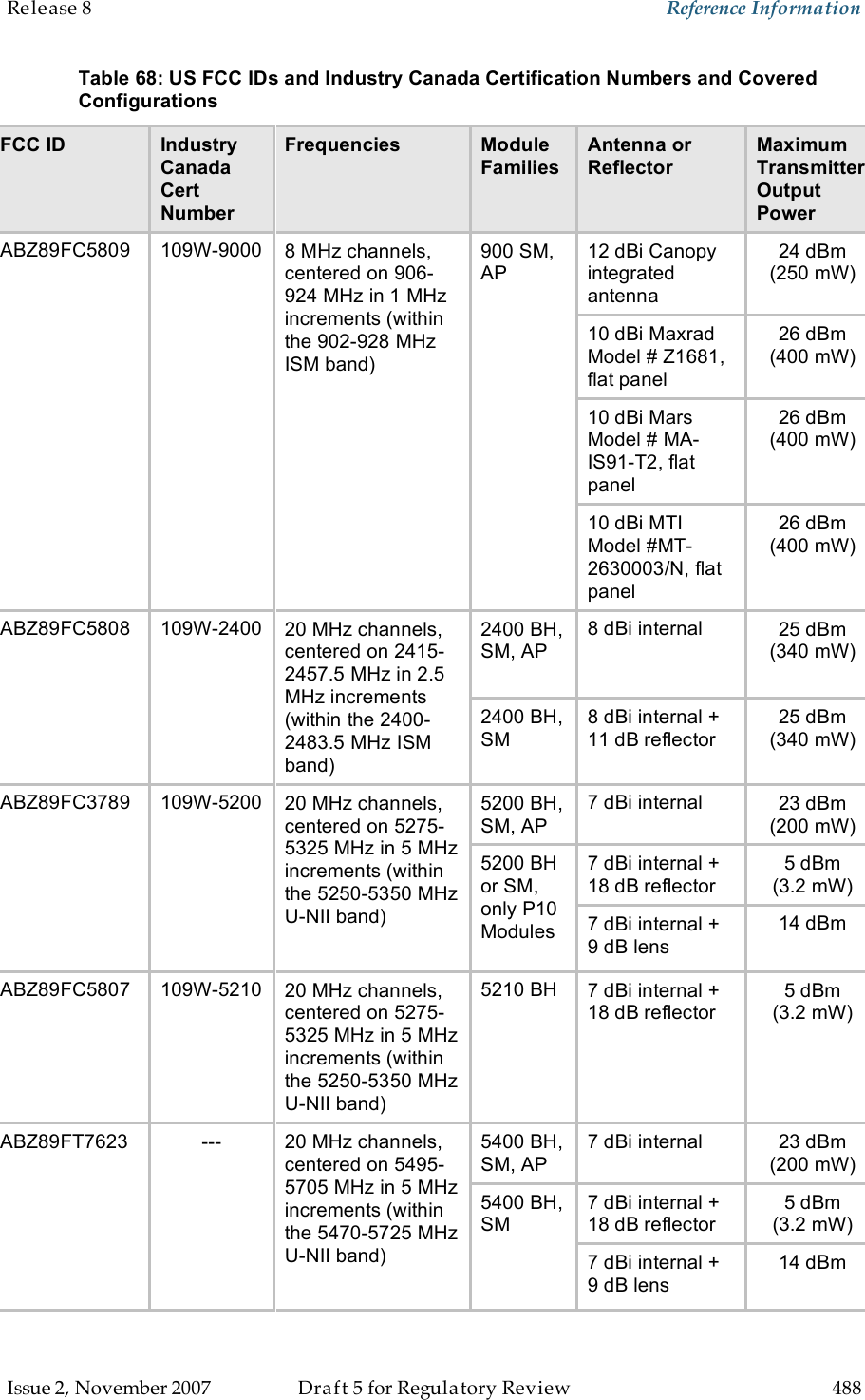
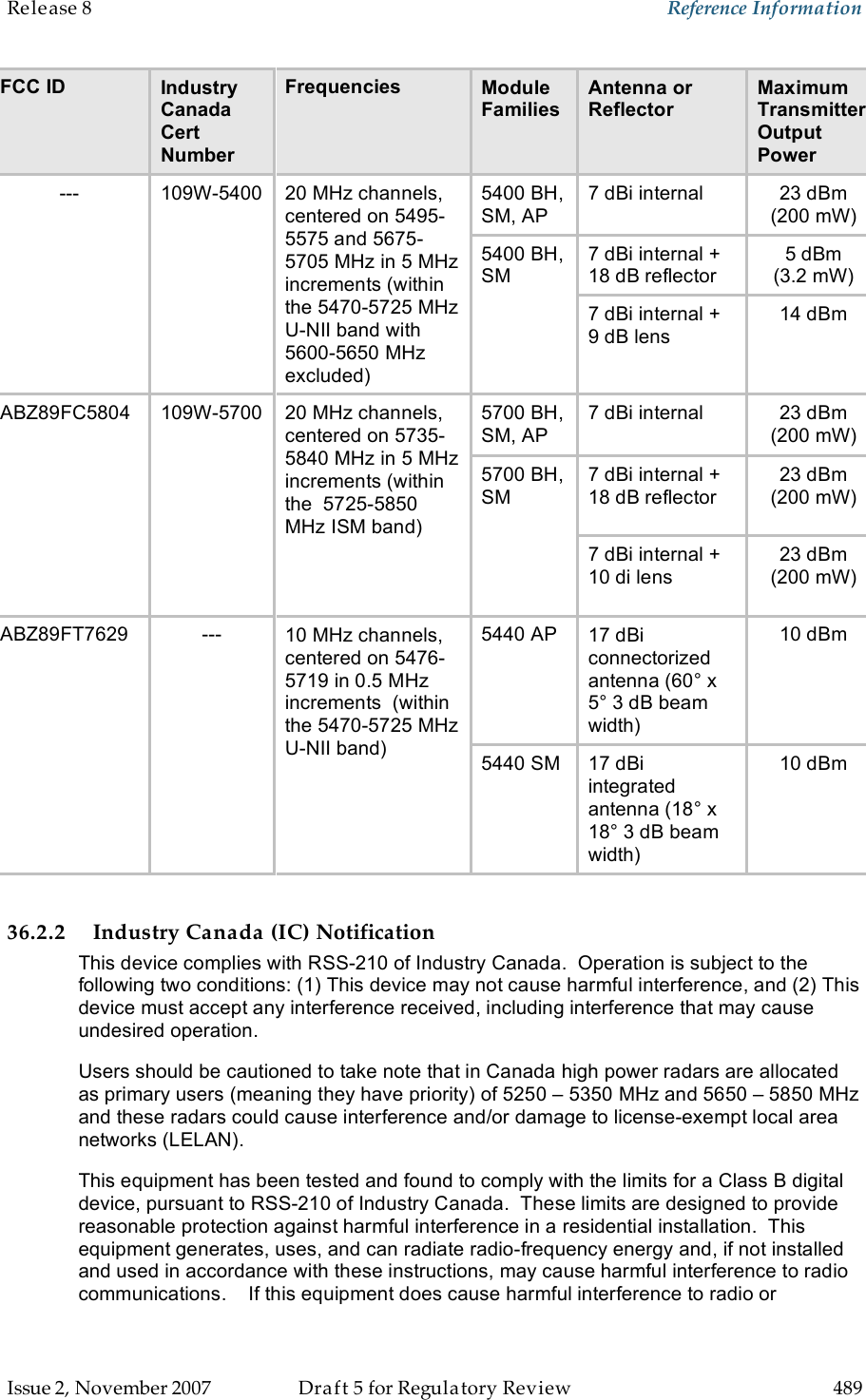
User Guide Part 5