Motorola Solutions 89FT7629 Access Point/CPE User Manual User Guide Part 5
Motorola Solutions, Inc. Access Point/CPE User Guide Part 5
Contents
- 1. User Guide Part 1
- 2. User Guide Part 2
- 3. User Guide Part 3
- 4. User Guide Part 4
- 5. User Guide Part 5
User Guide Part 5

Release 8 Operations Guide
Issue 2, November 2007 Draft 5 for Regulatory Review 401
CMMmicro
Object Name
Value Syntax
Operation
Allowed
pkts256to511Octets
Counter32
monitor
pkts512to1023Octets
Counter32
monitor
pkts64Octets
Counter32
monitor
pkts65to127Octets
Counter32
monitor
pldVersion
DisplayString
monitor
portIndex
Integer
monitor
portNumber
Integer
monitor
powerStatus
Integer
monitor
rxAlignmentErrors
Counter32
monitor
rxBroadcastPkts
Counter32
monitor
rxDropPkts
Counter32
monitor
rxExcessSizeDisc
Counter32
monitor
rxFCSErrors
Counter32
monitor
rxFragments
Counter32
monitor
rxGoodOctets
Counter64
monitor
rxJabbers
Counter32
monitor
rxMulticastPkts
Counter32
monitor
rxOctets
Counter64
monitor
rxOversizePkts
Counter32
monitor
rxPausePkts
Counter32
monitor
rxSAChanges
Counter32
monitor
rxSymbolErrors
Counter32
monitor
rxUndersizePkts
Counter32
monitor
rxUnicastPkts
Counter32
monitor
satellitesTracked
DisplayString
monitor
satellitesVisible
DisplayString
monitor
softwareVersion
DisplayString
monitor
syncStatus
DisplayString
monitor
systemTime
DisplayString
monitor
trackingMode
DisplayString
monitor
txBroadcastPkts
Counter32
monitor
txCollisions
Counter32
monitor
txDeferredTransmit
Counter32
monitor
txDropPkts
Counter32
monitor

Release 8 Operations Guide
Issue 2, November 2007 Draft 5 for Regulatory Review 402
CMMmicro
Object Name
Value Syntax
Operation
Allowed
txExcessiveCollision
Counter32
monitor
txFrameInDisc
Counter32
monitor
txLateCollision
Counter32
monitor
txMulticastPkts
Counter32
monitor
txMultipleCollision
Counter32
monitor
txOctets
Counter64
monitor
txPausePkts
Counter32
monitor
txSingleCollision
Counter32
monitor
txUnicastPkts
Counter32
monitor
upTime
DisplayString
monitor
24.5 OBJECTS DEFINED IN THE PTP 400 AND PTP 600 SERIES BRIDGES
MIB
The objects that the PTP 400 and PTP 600 series bridges’ MIB defines are listed in Table
64.
Table 63: PTP 400 and PTP 600 series bridge MIB objects
Object Name
Value Syntax
Operation
Allowed
iPAddress
IpAddress
manage
subnetMask
IpAddress
manage
gatewayIPAddress
IpAddress
manage
targetMACAddress1
DisplayString
manage
masterSlaveMode
Integer
manage
maximumTransmitPower
Integer
manage
receivePower2
Integer
manage
vectorError2
Integer
manage
transmitPower2
Integer
manage
range
Integer
manage
linkLoss2
Integer
manage
receiveChannel
Integer
manage
transmitChannel
Integer
manage
receiveModulationMode
Integer
manage
transmitModulationMode
Integer
manage
receiveSnr2
Integer
manage
systemReset
Integer
monitor

Release 8 Operations Guide
Issue 2, November 2007 Draft 5 for Regulatory Review 403
Object Name
Value Syntax
Operation
Allowed
softwareVersion
DisplayString
monitor
hardwareVersion
DisplayString
monitor
NOTES:
1. Of the other BH in the link.
2. max, mean, min, last during the past hour.
24.6 OBJECTS SUPPORTED IN THE CANOPY 30/60-Mbps BH
The 30/60-Mbps BH supports the following MIBs:
◦ MIB II, RFC 1213, System Group
◦ MIB II, RFC 1213, Interfaces Group
◦ WiMAX 802.16 WMAN-IF-MIB
◦ Bridge MIB, RFC 1493, dot1dBaseGroup
◦ Bridge MIB, RFC 1493, dot1dBasePortTableGroup
◦ 30/60-Mbps Backhaul Canopy proprietary MIB
24.7 OBJECTS SUPPORTED IN THE CANOPY 150/300-Mbps BH
The 150/300-Mbps BH supports the following MIBs:
◦ MIB II, RFC 1213, System Group
◦ MIB II, RFC 1213, Interfaces Group
◦ WiMAX 802.16 WMAN-IF-MIB
◦ Bridge MIB, RFC 1493, dot1dBaseGroup
◦ Bridge MIB, RFC 1493, dot1dBasePortTableGroup
◦ High-capacity counter MIB, RFC 2233
◦ 150/300-Mbps Backhaul Canopy proprietary MIB
24.8 INTERFACE DESIGNATIONS IN SNMP
SNMP identifies the ports of the module as follows:
◦ Interface 1 represents the Ethernet interface of the module. To monitor the status
of Interface 1 is to monitor the traffic on the Ethernet interface.
◦ Interface 2 represents the RF interface of the module. To monitor the status of
Interface 2 is to monitor the traffic on the RF interface.
These interfaces can be viewed on the NMS through definitions that are provided in the
standard MIB files.

Release 8 Operations Guide
Issue 2, November 2007 Draft 5 for Regulatory Review 404
24.9 TRAPS PROVIDED IN THE CANOPY ENTERPRISE MIB
Canopy modules provide the following SNMP traps for automatic notifications to the
NMS:
◦ whispGPSInSync, which signals a transition from not synchronized to
synchronized.
◦ whispGPSOutSync, which signals a transition from synchronized to not
synchronized.
◦ whispRegComplete, which signals registration completed.
◦ whispRegLost, which signals registration lost.
◦ whispRadarDetected, which signals that the one-minute scan has been
completed, radar has been detected, and the radio will shutdown.
◦ whispRadarEnd, which signals that the one-minute scan has been completed,
radar has not been detected, and the radio will resume normal operation.
NOTE:
The PTP 400 and PTP 600 series bridges do not support the traps listed above.
24.10 TRAPS PROVIDED IN THE PTP 400 SERIES BRIDGE MIB
PTP 400 series bridges (previously known as 30/60-Mbps Backhauls) provide the
following SNMP traps for automatic notifications to the NMS:
◦ coldStart
◦ linkUp
◦ linkDown
◦ dfsChannelChange, which signals that the channel has changed.
◦ dfsImpulsiveInterferenceDetected, which signals that impulsive interference has
been detected.
24.11 TRAPS PROVIDED IN THE PTP 600 SERIES BRIDGE MIB
PTP 600 series bridges (previously known as 150/300-Mbps Backhauls) provide the
following SNMP traps for automatic notifications to the NMS:
◦ coldStart
◦ linkUp
◦ linkDown
◦ dfsChannelChange, which signals that the channel has changed.
◦ dfsImpulsiveInterferenceDetected, which signals that impulsive interference has
been detected.

Release 8 Operations Guide
Issue 2, November 2007 Draft 5 for Regulatory Review 405
24.12 MIB VIEWERS
Any of several commercially available MIB viewers can facilitate management of these
objects through SNMP. Some are available as open source software. The Canopy
division does not endorse, support, or discourage the use of any these viewers.
To assist end users in this area, Canopy offers a starter guide for one of these viewers—
MRTG (Multi Router Traffic Grapher). This starter guide is titled Canopy Network
Management with MRTG: Application Note, and is available in the Document Library
section under Support at http://www.motorola.com/canopy. MRTG software is available at
http://mrtg.hdl.com/mrtg.html.
Other MIB viewers are available and/or described at the following web sites:
http://ns3.ndgsoftware.com/Products/NetBoy30/mibbrowser.html
http://www.adventnet.com/products/snmputilities/
http://www.dart.com/samples/mib.asp
http://www.edge-technologies.com/webFiles/products/nvision/index.cfm
http://www.ipswitch.com/products/whatsup/monitoring.html
http://www.koshna.com/products/KMB/index.asp
http://www.mg-soft.si/mgMibBrowserPE.html
http://www.mibexplorer.com
http://www.netmechanica.com/mibbrowser.html
http://www.networkview.com
http://www.newfreeware.com/search.php3?q=MIB+browser
http://www.nudesignteam.com/walker.html
http://www.oidview.com/oidview.html
http://www.solarwinds.net/Tools
http://www.stargus.com/solutions/xray.html
http://www.totilities.com/Products/MibSurfer/MibSurfer.htm

Release 8 Operations Guide
Issue 2, November 2007 Draft 5 for Regulatory Review 407
25 USING THE CANOPY NETWORK UPDATER TOOL
(CNUT)
The Canopy Network Updater Tool manages and automates the software and firmware
upgrade process for Canopy radio and CMMmicro modules across the network. This
eliminates the need for an administrator to visit each radio in the network (or each AP
while using the Autoupdate feature) to upgrade the modules.
25.1 CNUT FUNCTIONS
The Canopy Network Updater Tool
◦ automatically discovers all Canopy network elements
◦ executes a UDP command that initiates and terminates the Autoupdate mode
within APs. This command is both secure and convenient:
− For security, the AP accepts this command from only the IP address that you
specify in the Configuration page of the AP.
− For convenience, Network Updater automatically sets this Configuration
parameter in the APs to the IP address of the Network Updater server when
the server performs any of the update commands.
◦ allows you to choose among updating
− your entire network.
− only elements that you select.
− only network branches that you select.
◦ provides a Script Engine that you can use with any script that
− you define.
− Canopy supplies.
25.2 NETWORK ELEMENT GROUPS
With the Canopy Network Updater Tool, you can identify element groups composed of
network elements that you select. Identifying these element groups
◦ organizes the display of elements (for example, by region or by AP cluster).
◦ allows you to
− perform an operation on all elements in the group simultaneously.
− set group-level defaults for telnet or ftp password access and SNMP
Community String (defaults that can be overridden in an individual element
when necessary).
25.3 NETWORK LAYERS
A typical Canopy network contains multiple layers of elements, each layer lying farther
from the Point of Presence. For example, SMs are behind an AP and thus, in this context,
at a lower layer than the AP. Correctly portraying these layers in Network Updater is
essential so that Network Updater can perform radio and AP cluster upgrades in an
appropriate order.

Release 8 Operations Guide
Issue 2, November 2007 Draft 5 for Regulatory Review 408
IMPORTANT!
Correct layer information ensures that Network Updater does not command an
AP that is behind another AP/SM pair (such as in a remote AP installation) to
perform an upgrade at the same time as the SM that is feeding the AP. If this
occurs, then the remote AP loses network connection during the upgrade (when
the SM in front of the AP completes its upgrade and reboots).
25.4 SCRIPT ENGINE
Script Engine is the capability in Network Updater that executes any user-defined script
against any network element or element group. This capability is useful for network
management, especially for scripts that you repetitively execute across your network.
The Autodiscovery capability in Network Updater finds all of your Canopy network
elements. This comprehensive discovery
◦ ensures that, when you intend to execute a script against all elements, the script
is indeed executed against all elements.
◦ maintains master lists of elements (element groups) against which you
selectively execute scripts.
The following scripts are included with CNUT:
◦ AP Data Import from BAM
◦ AP Data Export to BAM
◦ Set Autoupdate Address on APs
◦ Set SNMP Accessibility
◦ Reset Unit
25.5 SOFTWARE DEPENDENCIES FOR CNUT
CNUT functionality requires
◦ one of the following operating systems
− Windows® 2000
− Windows XP
− Red Hat Linux 9
− Red Hat Enterprise Linux Version 3
◦ Java™ Runtime Version 1.4.2 or later
◦ Perl 5.8.0 or ActivePerl 5.8.3 software or later
25.6 CNUT DOWNLOAD
CNUT can be downloaded together with each Canopy system release that supports
CNUT. Software for these Canopy system releases is packaged on the Canopy Support
web page as either
◦ a .zip file for use without the CNUT application.
◦ a .pkg file that the CNUT application can open.

Release 8 Operations Guide
Issue 2, November 2007 Draft 5 for Regulatory Review 409
26 USING INFORMATIONAL TABS IN THE GUI
26.1 VIEWING GENERAL STATUS (ALL)
See
◦ General Status Tab of the AP on Page 201.
◦ General Status Tab of the SM on Page 198.
◦ General Status Tab of the BHM on Page 213.
◦ Beginning the Test of Point-to-Point Links on Page 210.
26.2 VIEWING SESSION STATUS (AP, BHM)
The Session Status tab in the Home page provides information about each SM that has
registered to the AP. This information is useful for managing and troubleshooting a
Canopy system. This tab also includes the current active values on each SM for MIR, CIR, and
VLAN, as well as the source of these values, representing the SM itself, BAM, or the AP and cap.
An example of the Session Status tab is displayed in Figure 142.
Figure 142: Session Status tab data, example
An additional example and explanations of the fields on this tab are provided in Session
Status Tab of the AP on Page 193.

Release 8 Operations Guide
Issue 2, November 2007 Draft 5 for Regulatory Review 410
26.3 VIEWING REMOTE SUBSCRIBERS (AP, BHM)
See
◦ Remote Subscribers Tab of the AP on Page 197.
◦ Continuing the Test of Point-to-Point Links on Page 212.
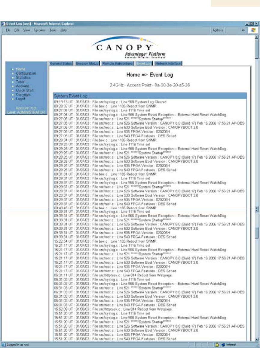
26.4 INTERPRETING MESSAGES IN THE EVENT LOG (ALL)
Each line in the Event Log of a module Home page begins with a time and date stamp.
However, some of these lines wrap as a combined result of window width, browser
preferences, and line length. You may find this tab easiest to use if you widen the window
until all lines are shown as beginning with the time and date stamp.
26.4.1 Time and Date Stamp
The time and date stamp reflect either
◦ GPS time and date directly or indirectly received from the CMM.
◦ the running time and date that you have set in the Time & Date web page.
NOTE:
In the Time & Date web page, if you have left any time field or date field unset
and clicked the Set Time and Date button, then the time and date default to
00:00:00 UT : 01/01/00.
A reboot causes the preset time to pause or, in some cases, to run in reverse.
Additionally, a power cycle resets the running time and date to the default
00:00:00 UT : 01/01/00. Thus, whenever either a reboot or a power cycle has
occurred, you should reset the time and date in the Time & Date web page of
any module that is not set to receive sync.
26.4.2 Event Log Data Collection
The collection of event data continues through reboots and power cycles. When the
buffer allowance for event log data is reached, the system adds new data into the log and
discards an identical amount of the oldest data.
Each line that contains the expression WatchDog flags an event that was both
◦ considered by the system software to have been an exception
◦ recorded in the preceding line.
Conversely, a Fatal Error() message flags an event that is recorded in the next line. Some
exceptions and fatal errors may be significant and require either operator action or
technical support.
An example portion of Event Log data is displayed in Figure 143. In this figure (unlike in
the Event Log web page)
◦ lines are alternately highlighted to show the varying length of wrapped lines.
◦ the types of event messages (which follow the time and date stamps and the file
and line references) are underscored as quoted in Table 64 and Table 65.
Release 8 Operations Guide
Issue 2, November 2007 Draft 5 for Regulatory Review 411
Figure 143: Event Log tab data, example

Release 8 Operations Guide
Issue 2, November 2007 Draft 5 for Regulatory Review 412
26.4.3 Messages that Flag Abnormal Events
The messages listed in Table 64 flag abnormal events and, case by case, may signal the
need for corrective action or technical support. See Troubleshooting on Page 463.
Table 64: Event Log messages for abnormal events
Event Message
Meaning
Expected LUID = 6 Actual
LUID = 7
Something is interfering with the control messaging of the
module. Also ensure that you are using shielded cables to
minimize interference. Consider trying different frequency
options to eliminate or reduce interference.
FatalError()
The event recorded on the line immediately beneath this
message triggered the Fatal Error().
Loss of GPS Sync Pulse
Module has lost GPS sync signal.
Machine Check Exception
This is a symptom of a possible hardware failure. If this is
a recurring message, begin the RMA process for the
module.
RcvFrmNum = 0x00066d
ExpFrmNum = 0x000799
Something is interfering with the control messaging of the
module. Also ensure that you are using shielded cables to
minimize interference. Consider trying different frequency
options to eliminate or reduce interference.
System Reset Exception -- External
Hard Reset
The unit lost power or was power cycled.
System Reset Exception -- External
Hard Reset WatchDog
The event recorded on the preceding line triggered this
WatchDog message.
26.4.4 Messages that Flag Normal Events
The messages listed in Table 65 record normal events and typically do not signal a need
for any corrective action or technical support.
Table 65: Event Log messages for normal events
Event Message
Meaning
Acquired GPS Sync Pulse.
Module has acquired GPS sync signal.
FPGA Features
Type of encryption.
FPGA Version
FPGA (JBC) version in the module.
GPS Date/Time Set
Module is now on GPS time.
PowerOn reset from Telnet
command line
Reset command was issued from a telnet session.
Reboot from Webpage
Module was rebooted from management interface.
Software Boot Version
Boot version in the module.
Software Version
Canopy release version and authentication method for the unit.
System Log Cleared
Event log was manually cleared.
Release 8 Operations Guide
Issue 2, November 2007 Draft 5 for Regulatory Review 413
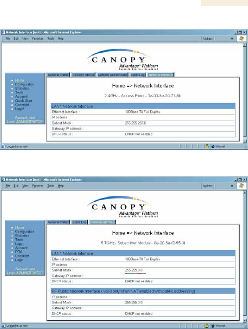
26.5 VIEWING THE NETWORK INTERFACE TAB (ALL)
Figure 144: Network Interface tab of AP, example
Figure 145: Network Interface tab of SM, example
In any module, the LAN1 Network Interface section of this tab displays the defined
Internet Protocol scheme for the Ethernet interface to the module. In slave devices, this
tab also provides an RF Public Network Interface section, which displays the Internet
Protocol scheme defined for network access through the master device (AP or BHM).
Release 8 Operations Guide
Issue 2, November 2007 Draft 5 for Regulatory Review 414
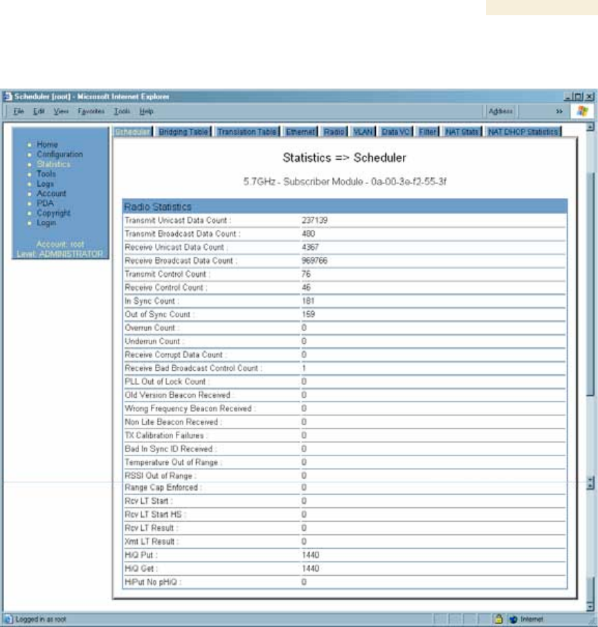
26.6 INTERPRETING RADIO STATISTICS IN THE SCHEDULER TAB
(ALL)
Figure 146: Scheduler tab of SM, example
Statistics for the Scheduler are displayed as shown in Figure 146.
Release 8 Operations Guide
Issue 2, November 2007 Draft 5 for Regulatory Review 415
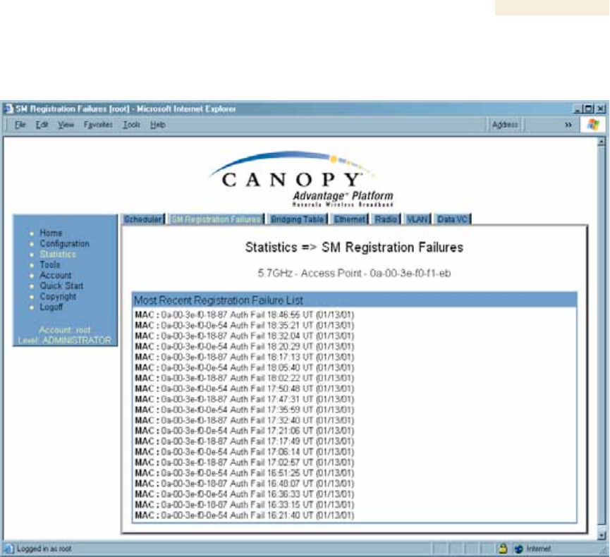
26.7 VIEWING THE LIST OF REGISTRATION FAILURES (AP, BHM)
An example of the SM Registration Failures tab is displayed in Figure 147.
Figure 147: SM Registration Failures tab of AP, example
The SM Registration Failures tab identifies SMs (or BHSs) that have recently attempted
and failed to register to this AP (or BHM). With its time stamps, these instances may
suggest that a new or transient source of interference exists.
Release 8 Operations Guide
Issue 2, November 2007 Draft 5 for Regulatory Review 416
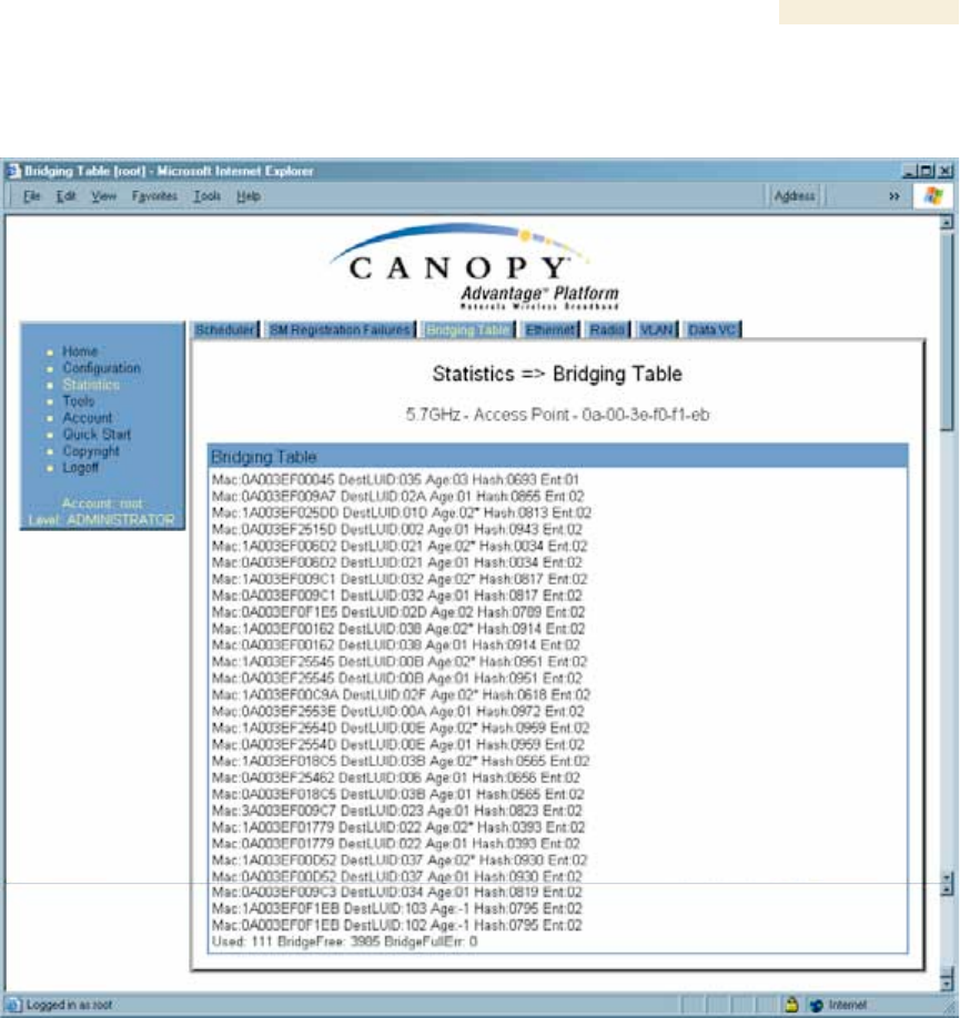
26.8 INTERPRETING DATA IN THE BRIDGING TABLE (ALL)
An example of the Bridging Table tab is displayed in Figure 148.
Figure 148: Bridging Table tab of AP, example
If NAT (network address translation) is not active on the SM, then the Bridging Table tab
provides the MAC address of all devices that are attached to registered SMs (identified
by LUIDs). The bridging table allows data to be sent to the correct module as follows:
◦ For the AP, the uplink is from RF to Ethernet. Thus, when a packet arrives in the
RF interface to the AP, the AP reads the MAC address from the inbound packet
and creates a bridging table entry of the source MAC address on the other end of
the RF interface.
◦ For the SM, BHM, and BHS, the uplink is from Ethernet to RF. Thus, when a
packet arrives in the Ethernet interface to one of these modules, the module
reads the MAC address from the inbound packet and creates a bridging table
entry of the source MAC address on the other end of the Ethernet interface.
Release 8 Operations Guide
Issue 2, November 2007 Draft 5 for Regulatory Review 417
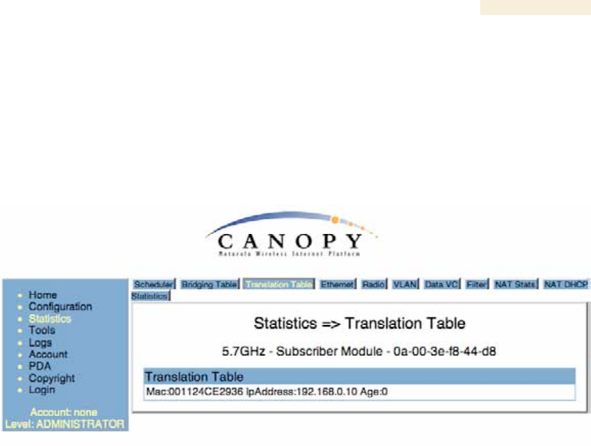
26.9 TRANSLATION TABLE (SM)
When Translation Bridging is enabled in the AP, each SM keeps a table mapping MAC
addresses of devices attached to the AP to IP addresses, as otherwise the mapping of
end-user MAC addresses to IP addresses is lost. (When Translation Bridging is enabled,
an AP modifies all uplink traffic originating from registered SM’s such that the source
MAC address of every packet will be changed to that of the SM which bridged the packet
in the uplink direction.)
An example of the Translaton Table is displayed in Figure 149.
Figure 149: Translation Table tab of SM, example
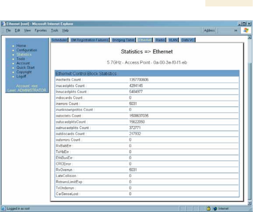
26.10 INTERPRETING DATA IN THE ETHERNET TAB (ALL)
The Ethernet tab of the Statistics web page reports TCP throughput and error information
for the Ethernet connection of the module.
Release 8 Operations Guide
Issue 2, November 2007 Draft 5 for Regulatory Review 418
Figure 150: Ethernet tab of AP, example
The Ethernet tab displays the following fields.
inoctets Count
This field displays how many octets were received on the interface, including those that
deliver framing information.
inucastpkts Count
This field displays how many inbound subnetwork-unicast packets were delivered to a
higher-layer protocol.
Innucastpkts Count
This field displays how many inbound non-unicast (subnetwork-broadcast or subnetwork-
multicast) packets were delivered to a higher-layer protocol.
indiscards Count
This field displays how many inbound packets were discarded without errors that would
have prevented their delivery to a higher-layer protocol. (Some of these packets may
have been discarded to increase buffer space.)
inerrors Count
This field displays how many inbound packets contained errors that prevented their
delivery to a higher-layer protocol.

Release 8 Operations Guide
Issue 2, November 2007 Draft 5 for Regulatory Review 419
inunknownprotos Count
This field displays how many inbound packets were discarded because of an unknown or
unsupported protocol.
outoctets Count
This field displays how many octets were transmitted out of the interface, including those
that deliver framing information.
outucastpkts Count
This field displays how many packets for which the higher-level protocols requested
transmission to a subnetwork-unicast address. The number includes those that were
discarded or not sent.
outnucastpkts Count
This field displays how many packets for which the higher-level protocols requested
transmission to a non-unicast (subnetwork-broadcast or subnetwork-multicast) address.
The number includes those that were discarded or not sent.
outdiscards Count
This field displays how many outbound packets were discarded without errors that would
have prevented their transmission. (Some of these packets may have been discarded to
increase buffer space.)
outerrrors Count
This field displays how many outbound packets contained errors that prevented their
transmission.
RxBabErr
This field displays how many receiver babble errors occurred.
EthBusErr
This field displays how many Ethernet bus errors occurred on the Ethernet controller.
CRCError
This field displays how many CRC errors occurred on the Ethernet controller.
RxOverrun
This field displays how many receiver overrun errors occurred on the Ethernet controller.
Late Collision
This field displays how many late collisions occurred on the Ethernet controller. A normal
collision occurs during the first 512 bits of the frame transmission. A collision that occurs
after the first 512 bits is considered a late collision.
IMPORTANT!
A late collision is a serious network problem because the frame being
transmitted is discarded. A late collision is most commonly caused by a
mismatch between duplex configurations at the ends of a link segment.
Release 8 Operations Guide
Issue 2, November 2007 Draft 5 for Regulatory Review 420
RetransLimitExp
This field displays how many times the retransmit limit has expired.
TxUnderrun
This field displays how many transmission-underrun errors occurred on the Ethernet
controller.
CarSenseLost
This field displays how many carrier sense lost errors occurred on the Ethernet controller.
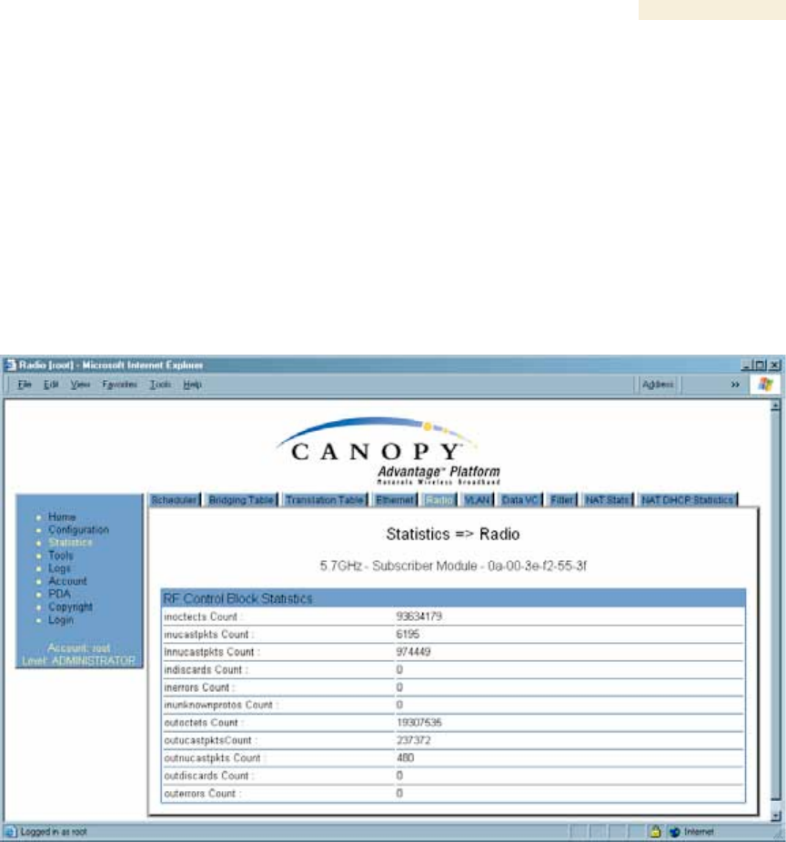
26.11 INTERPRETING RF CONTROL BLOCK STATISTICS IN THE RADIO
TAB (ALL)
Figure 151: Radio tab of Statistics page in SM, example
The Radio tab of the Statistics page displays the following fields.
inoctets Count
This field displays how many octets were received on the interface, including those that
deliver framing information.
inucastpkts Count
This field displays how many inbound subnetwork-unicast packets were delivered to a
higher-layer protocol.
Innucastpkts Count
This field displays how many inbound non-unicast (subnetwork-broadcast or subnetwork-
multicast) packets were delivered to a higher-layer protocol.

Release 8 Operations Guide
Issue 2, November 2007 Draft 5 for Regulatory Review 421
indiscards Count
This field displays how many inbound packets were discarded without errors that would
have prevented their delivery to a higher-layer protocol. (Some of these packets may
have been discarded to increase buffer space.)
inerrors Count
This field displays how many inbound packets contained errors that prevented their
delivery to a higher-layer protocol.
inunknownprotos Count
This field displays how many inbound packets were discarded because of an unknown or
unsupported protocol.
outoctets Count
This field displays how many octets were transmitted out of the interface, including those
that deliver framing information.
outucastpkts Count
This field displays how many packets for which the higher-level protocols requested
transmission to a subnetwork-unicast address. The number includes those that were
discarded or not sent.
outnucastpkts Count
This field displays how many packets for which the higher-level protocols requested
transmission to a non-unicast (subnetwork-broadcast or subnetwork-multicast) address.
The number includes those that were discarded or not sent.
outdiscards Count
This field displays how many outbound packets were discarded without errors that would
have prevented their transmission. (Some of these packets may have been discarded to
increase buffer space.)
outerrrors Count
This field displays how many outbound packets contained errors that prevented their
transmission.
26.12 INTERPRETING DATA IN THE VLAN TAB (AP, SM)
The VLAN tab in the Statistics web page provides a list of the most recent packets that
were filtered because of VLAN membership violations. An example of the VLAN tab is
shown in Figure 152.
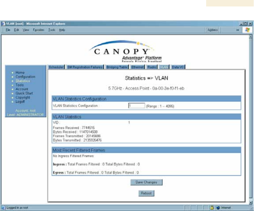
Release 8 Operations Guide
Issue 2, November 2007 Draft 5 for Regulatory Review 422
Figure 152: VLAN tab of AP, example
Interpret entries under Most Recent Filtered Frames as follows:
◦ Unknown—This should not occur. Contact Canopy Technical Support.
◦ Only Tagged—The packet was filtered because the configuration is set to
accept only packets that have an 802.1Q header, and this packet did not.
◦ Ingress—When the packet entered through the wired Ethernet interface,
the packet was filtered because it indicated an incorrect VLAN membership.
◦ Local Ingress—When the packet was received from the local TCP/IP stack,
the packet was filtered because it indicated an incorrect VLAN membership.
This should not occur. Contact Canopy Technical Support.
◦ Egress—When the packet attempted to leave through the wired Ethernet
interface, the packet was filtered because it indicated an incorrect VLAN
membership.
◦ Local Egress—When the packet attempted to reach the local TCP/IP stack,
the packet was filtered because it indicated an incorrect VLAN membership.
Release 8 Operations Guide
Issue 2, November 2007 Draft 5 for Regulatory Review 423
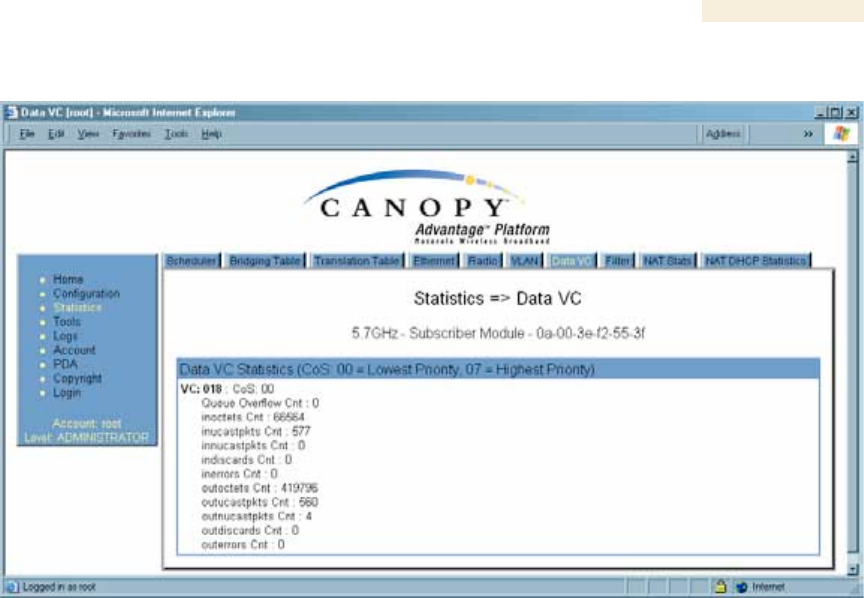
26.13 DATA VC (ALL)
Figure 153: Data VC tab of SM, example
The Data VC tab page displays the following fields.
VC
This field displays the virtual channel number. Low priority channels start at VC18 and
count up. High priority channels start at VC255 and count down. If one VC is displayed,
the high-priority channel is disabled. If two are displayed, the high-priority channel is
enabled
CoS
This field displays the Class of Service for the virtual channel. The low priority channel is
a CoS of 00, and the high priority channel is a CoS of 01. CoS of 02 through 07 are not
currently used.
Queue Overflow Cnt
This is a count of packets that were discarded because the queue for the VC was
already full.
inoctets Cnt
This field displays how many octets were received on the interface, including those that
deliver framing information.
inucastpkts Cnt
This field displays how many inbound subnetwork-unicast packets were delivered to a
higher-layer protocol.
Innucastpkts Cnt
This field displays how many inbound non-unicast (subnetwork-broadcast or subnetwork-
multicast) packets were delivered to a higher-layer protocol.

Release 8 Operations Guide
Issue 2, November 2007 Draft 5 for Regulatory Review 424
indiscards Cnt
This field displays how many inbound packets were discarded without errors that would
have prevented their delivery to a higher-layer protocol. (Some of these packets may
have been discarded to increase buffer space.)
inerrors Cnt
This field displays how many inbound packets contained errors that prevented their
delivery to a higher-layer protocol.
outoctets Cnt
This field displays how many octets were transmitted out of the interface, including those
that deliver framing information.
outucastpkts Cnt
This field displays how many packets for which the higher-level protocols requested
transmission to a subnetwork-unicast address. The number includes those that were
discarded or not sent.
outnucastpkts Cnt
This field displays how many packets for which the higher-level protocols requested
transmission to a non-unicast (subnetwork-broadcast or subnetwork-multicast) address.
The number includes those that were discarded or not sent.
outdiscards Cnt
This field displays how many outbound packets were discarded without errors that would
have prevented their transmission. (Some of these packets may have been discarded to
increase buffer space.)
outerrrors Cnt
This field displays how many outbound packets contained errors that prevented their
transmission.
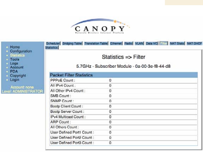
26.14 FILTER (SM)
The Filter tab displays statistics on packets that have been filtered (dropped) due to the
filters set on the SM’s Protocol Filtering tab. An example of the Filter tab is shown in
Figure 154.
Release 8 Operations Guide
Issue 2, November 2007 Draft 5 for Regulatory Review 425
Figure 154: Filter tab on SM, example
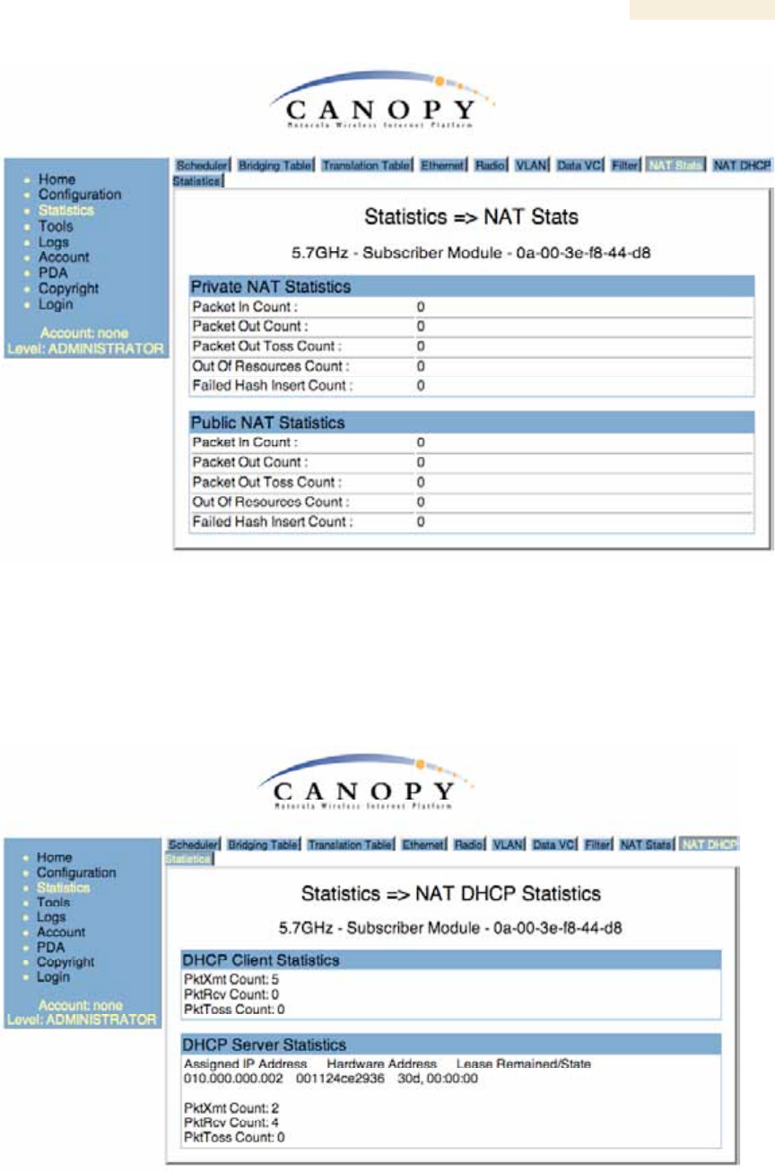
26.15 NAT STATS (SM)
When NAT is enabled on an SM, statistics are kept on the Public and Private (WAN and
LAN) sides of the NAT, and displayed on the NAT Stats tab. An example of the NAT
Stats tab is shown in Figure 155.
Release 8 Operations Guide
Issue 2, November 2007 Draft 5 for Regulatory Review 426
Figure 155: Nat Stats tab on SM, example
26.15.1 NAT DHCP Statistics (SM)
When NAT is enable on an SM with DHCP client and/or Server, statistics are kept for
packets transmitted, received, and tossed, as well as a table of lease information for the
DHCP server (Assigned IP Address, Hardware Address, and Lease Remained/State). An
example of the NAT DHCP Statistics tab is shown in Figure 156.
Figure 156: NAT DHCP Statistics tab in SM, example

Release 8 Operations Guide
Issue 2, November 2007 Draft 5 for Regulatory Review 427
26.15.2 Interpreting Data in the GPS Status Page (AP, BHM)
The GPS Status tab is only displayed when the Sync Input is set to Sync to Received
Signal (Timing Port), which is the configuration desired when connecting an AP or BHM
to a CMM2. See Sync Input on Page 237.
The page displays information similar to that available on the web pages of a CMM3,
including Pulse Status, GPS Time and Date, Satellites Tracked, Available Satellites,
Height, Lattitude and Longitude. This page also displays the state of the antenna in the
Antenna Connection field as
◦ Unknown—Shown for early CMM2s.
◦ OK—Shown for later CMM2s where no problem is detected in the signal.
◦ Overcurrent—Indicates a coax cable or connector problem.
◦ Undercurrent—Indicates a coax cable or connector problem.
IMPORTANT!
If Unknown is displayed where a later CMM2 is deployed, then the connection is
not working but the reason is unknown.
This information may be helpful in a decision of whether to climb a tower to diagnose a
perceived antenna problem.
Release 8 Operations Guide
Issue 2, November 2007 Draft 5 for Regulatory Review 429
27 USING TOOLS IN THE GUI
27.1 USING THE SPECTRUM ANALYZER TOOL (SM, BHS)
See Monitoring the RF Environment on Page 363.
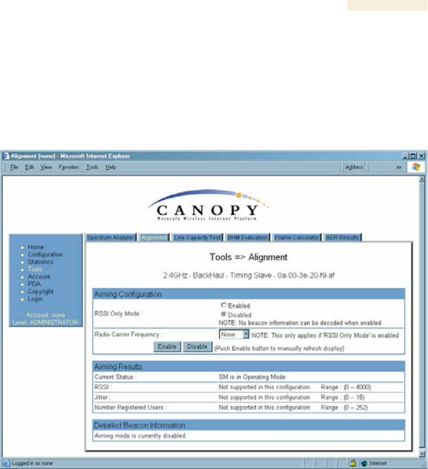
27.2 USING THE ALIGNMENT TOOL (SM, BHS)
An example of the Alignment tab in an SM or BHS is displayed in Figure 157.
Figure 157: Alignment tab of BHS, example
Proper alignment must achieve all of the following indications for an acceptable link
between the modules:
◦ RSSI typically at least 10 dBM above receiver sensitivity
◦ jitter value between 0 and 4
◦ uplink and downlink efficiency greater than 90%, except as described under
Comparing Efficiency in 1X Operation to Efficiency in 2X Operation on Page 135.

Release 8 Operations Guide
Issue 2, November 2007 Draft 5 for Regulatory Review 430
IMPORTANT!
If any of these values is not achieved, a link can be established but will manifest
occasional problems.
In the Alignment tab, you may set the following parameters.
RSSI Only Mode
In the RSSI Only Mode, the screen displays the signal strength based on the amount of
energy in the selected frequency, regardless of whether the module has registered. This
mode simplifies the aiming process for long links. To invoke the RSSI Only Mode, select
Enabled.
Radio Carrier Frequency
If you enabled the RSSI Only Mode, select the frequency (in MHz) for the aiming
operation.
The Alignment tab also provides the following buttons.
Enable
A click of this button launches the slave device into alignment mode. Each further click
refreshes the data in the tab to display the latest measurements collected.
Disable
A click of this button changes the slave device from alignment mode back to operating
mode.
The Alignment tab also provides the following read-only fields.
Current Status
This field indicates either SM is in Alignment Mode or SM is in Operating
Mode. This syntax is used in an SM and in a BHS.
RSSI
This field displays the Radio Signal Strength Indicator units and, in parentheses, the
current power level, of the signal received from the AP or BHM.
Jitter
This field displays the jitter level of the signal received from the AP or BHM.
Number Registered Users
This field displays how many slave devices are currently registered to the master device
whose beacon is being received during the aiming period.
In addition, the Alignment tab includes the following Detailed Beacon Information where it
is available.

Release 8 Operations Guide
Issue 2, November 2007 Draft 5 for Regulatory Review 431
Average measured RSSI
This field displays the Radio Signal Strength Indicator units and, in parentheses, the
power level as an average of the measurements that were collected throughout the
aiming period. Try for the highest power level that you can achieve at the least amount of
jitter. For example, if you achieve a power level of −75 dBm with a jitter level of 5, and
further refine the alignment to achieve a power level of −78 dBm with a jitter level of 2
or 3, the link is better because of the further refinement.
Average measured Jitter
This field displays Jitter as an average of the measurements that were collected
throughout the aiming period. In 1X operation, jitter values of 0 to 4 are acceptable. In 2X
operation, jitter values 0 to 9 are acceptable. In either mode, 0 to 15 is the range of
possible values that the Jitter field reports. Within the acceptable range, incremental
improvements in the jitter level achieved can significantly improve link quality where
power level is not significantly diminished by re-aiming.
Users
This is a count of the number of SMs registered to the AP you are aligning to.
Frequency
This field displays the frequency in MHz of the signal that was being received during the
aiming period.
ESN
This field displays the MAC address of the AP or BHM you are aligning to.
Color Code
This field displays the color code of the AP or BHM you are aligning to.
Backhaul
This field displays a 1 if the device you are aligning to is a BHM, and a 0 if the device you
are aligning to is an AP.
Release 8 Operations Guide
Issue 2, November 2007 Draft 5 for Regulatory Review 432
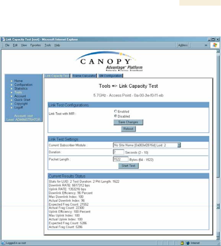
27.3 USING THE LINK CAPACITY TEST TOOL (ALL)
An example of the Link Capacity Test tab is displayed in Figure 158.
Figure 158: Link Capacity Test tab with 1522-byte packet length, example
The Link Capacity Test page allows you to measure the throughput and efficiency of the
RF link between two Canopy modules. Many factors, including packet length, affect
throughput. The Link Capacity Test tab contains the settable parameter Packet Length
with a range of 64 to 1522 bytes. This allows you to compare throughput levels that result
from various packet sizes.
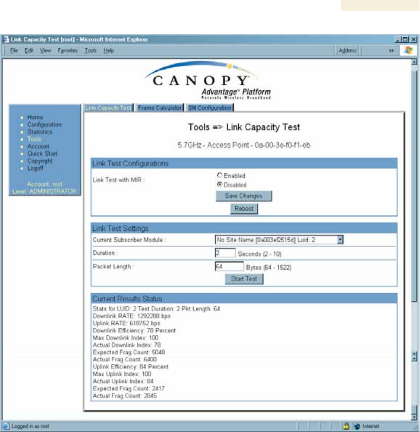
For example, the same link was measured in the same time frame at a packet length of
64 bytes. The results are shown in Figure 159.
Release 8 Operations Guide
Issue 2, November 2007 Draft 5 for Regulatory Review 433
Figure 159: Link Capacity Test tab with 64-byte packet length, example
To test a link, perform the following steps.
Procedure 40: Performing a Link Capacity Test
1. Access the Link Capacity Test tab in the Tools web page of the module.
2. If you are running this test from an AP
a. and you want to see Maximum Information Rate (MIR) data for the SM
whose link you will be testing, then perform the following steps:
(1) For Link Test with MIR, select Enabled.
(2) Click the Save Changes button.
(3) Click the Reboot button.
b. use the drop-down list to select the SM whose link you want to test.

Release 8 Operations Guide
Issue 2, November 2007 Draft 5 for Regulatory Review 434
3. Type into the Duration field how long (in seconds) the RF link should be tested.
4. Type into the Packet Length field the packet length at which you want the test
conducted.
5. Type into the Number of Packets field either
◦ the number of packets (1 to 64) for the test.
◦ 0 to flood the link for as long as the test is in progress.
6. Click the Start Test button.
7. In the Current Results Status block of this tab, view the results of the test.
8. Optionally
a. change the packet length.
b. repeat Steps 5 and 6.
c. compare the results to those of other tests.
=========================== end of procedure ===========================
The key fields in the test results are
◦ Downlink RATE and Uplink RATE, expressed in bits per second
◦ Downlink Efficiency and Uplink Efficiency, expressed as a percentage
A Canopy system link is acceptable only if the efficiencies of the link test are greater than
90% in both the uplink and downlink direction, except during 2X operation. See Using
Link Efficiency to Check Received Signal Quality on Page 135. Whenever you install a
new link, execute a link test to ensure that the efficiencies are within recommended
guidelines.
The AP downlink data percentage, slot settings, other traffic in the sector, and the quality
of the RF environment all affect throughput. However, a Maximum Information Rate
(MIR) throttle or cap on the SM does not affect throughput.
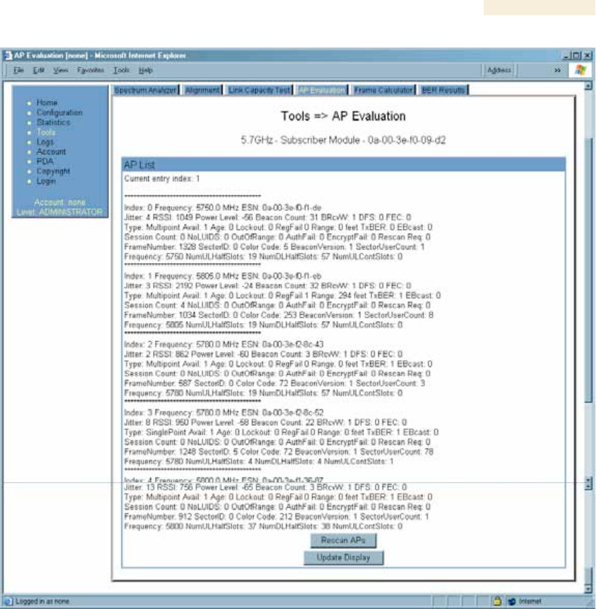
27.4 USING THE AP EVALUATION OR BHM EVALUATION TOOL
(SM, BHS)
The AP Evaluation tab in the Tools web page of the SM provides information about the
AP that the SM sees. Similarly, the BHM Evaluation tab of the BHS provides information
about the BHM. An example of the AP Evaluation tab is shown in Figure 160.
NOTE:
The data for this page can be suppressed by the SM Display of AP Evaluation
Data selection in the Security tab of the Configuration page in the AP.
Release 8 Operations Guide
Issue 2, November 2007 Draft 5 for Regulatory Review 435
Figure 160: AP Evaluation tab of SM, example
The AP Evaluation tab provides the following fields that can be useful to manage and
troubleshoot a Canopy system:
Index
This field displays the index value that the Canopy system assigns (for only this page) to
the AP where this SM is registered (or to the BHM to which this BHS is registered).
Frequency
This field displays the frequency that the AP or BHM transmits.
ESN
This field displays the MAC address (electronic serial number) of the AP or BHM.

Release 8 Operations Guide
Issue 2, November 2007 Draft 5 for Regulatory Review 436
Jitter, RSSI, and Power Level
The AP Evaluation tab shows the received Power Level in dBm and Jitter. Proper
alignment maximizes Power Level and minimizes Jitter. As you refine alignment, you
should favor lower jitter over higher dBm. For example, if coarse alignment gives an SM
a power level of −75 dBm and a jitter measurement of 5, and further refining
the alignment drops the power level to −78 dBm and the jitter to 2 or 3, use the refined
alignment, with the following caveats:
◦ When the receiving link is operating at 1X, the Jitter scale is 0 to 15 with desired
jitter between 0 and 4.
◦ When the receiving link is operating at 2X, the Jitter scale is 0 to 15 with desired
jitter between 0 and 9.
For historical relevance, the AP Evaluation tab also shows the RSSI, the unitless
measure of power. Use Power Level and ignore RSSI. RSSI implies more accuracy and
precision than is inherent in its measurement.
NOTE:
Unless the page is set to auto-refresh, the values displayed are from the instant
the General Status tab was selected. To keep a current view of the values,
refresh the browser screen or set to auto-refresh.
Beacon Count
A count of the beacons seen in a given time period.
BRcvW
DFS
FEC
Type
Multipoint indicates an AP, not a BHM.
Age
Lockout
This field displays how many times the SM or BHS has been temporarily locked out of
making registration attempts.
RegFail
This field displays how many registration attempts by this SM or BHS failed.
Range
This field displays the distance in feet for this link. To derive the distance in meters,
multiply the value of this parameter by 0.3048.
TxBER
A 1 in this field indicates the AP or BHM is sending Radio BER.

Release 8 Operations Guide
Issue 2, November 2007 Draft 5 for Regulatory Review 437
EBcast
A 1 in this field indicates the AP or BHM is encrypting broadcasst packets. A 0 indicates it
is not.
Session Count
This field displays how many sessions the SM (or BHS) has had with the AP (or BHM).
Typically, this is the sum of Reg Count and Re-Reg Count. However, the result of internal
calculation may display here as a value that slightly differs from the sum.
In the case of a multipoint link, if the number of sessions is significantly greater than the
number for other SMs, then this may indicate a link problem or an interference problem.
NoLUIDs
OutOfRange
AuthFail
This field displays how many times authentication attempts from this SM have failed in
the AP.
EncryptFail
This field displays how many times an encryption mismatch has occurred between
the SM and the AP.
Rescan Req
FrameNumber
Sector ID
This field displays the value of the Sector ID field that is provisioned for the AP or BHM.
Color Code
This field displays the value of the Color Code field that is provisioned for the AP or
BHM.
BeaconVersion
Sector User Count
This field displays how many SMs are registered on the AP.
Frequency
This field displays the frequency of the received signal, expressed in MHz.
NumULHalfSlots
This is the number of uplink half slots in this AP or BHM’s frame. To get slots, just divide
by 2.
NumDLHalfSlots
This is the number of downlink half slots in this AP or BHM’s frame. To get slots, just
divide by 2.

Release 8 Operations Guide
Issue 2, November 2007 Draft 5 for Regulatory Review 438
NumULContSlots
This field displays how many control slots are being used in the uplink portion of the
frame.
The AP Evaluation tab also provides the following buttons.
Rescan APs
You can click this button to force the SM or BHS to rescan the frequencies that are
selected in the Radio tab of the Configuration page. (See Custom Radio Frequency Scan
Selection List on Page 273.) This module will then register to the AP or BHM that
provides the best results for power level, jitter, and—in an SM—the number of registered
SMs.
Update Display
You can click this button to gather updated data without causing the SM or BHS to
rescan and re-register.
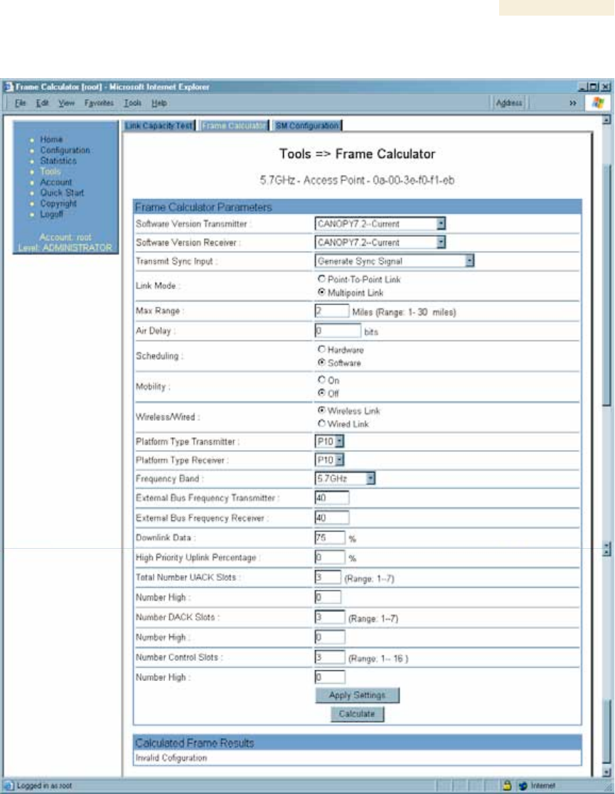
27.5 USING THE FRAME CALCULATOR TOOL (ALL)
Canopy avoids self-interference by syncing collocated APs (so they begin each
transmission cycle at the same time) and requiring that collocated APs have the same
transmit/receive ratio (so they stop transmitting and start receiving at the same time).
This ensures that, at any instant, they are either all receiving or all transmitting.
This avoids, for example, the problem of one AP attempting to receive from a distant SM,
while a nearby AP is transmitting and overpowering the signal from the distant SM.
Parameters that affect transmit/receive ratio include range, slots, downlink data
percentage, and high priority uplink percentage. All collocated APs must have the same
transmit/receive ratio. Additional engineering is needed for setting the parameters in a
mixed cluster – one with APs on hardware scheduler and APs on software scheduler.
A frame calculator helps to do this. The operator inputs various AP settings into the
calculator, and the calculator outputs many details on the frame including the Uplink Rcv
SQ Start. This calculation should be done for each AP that has different settings. Then
the operator varies the Downlink Data percentage in each calculation until the calculated
Uplink Rcv SQ Start for all collocated APs is within 300 time bits. The frame calculator is
accessed by clicking on Expanded Stats in the navigation column, then clicking on Frame
Calculator (at the bottom of the expanded navigation column).
The calculator does not use data on the module or populate new data. It is merely a
convenience application running on the module. For this reason, you can use any module
to do the calculations for any AP. Running the calculator on the AP in question is not
necessary.
IMPORTANT!
APs with slightly mismatched transmit/receive ratios and low levels of data traffic
may see little effect on throughput. As the data traffic increases, the impact of
mismatched transmit/receive ratios will increase. This means that a system that
was not tuned for collocation may work fine at low traffic levels, but encounter
problems at higher traffic level. The conservative practice is to tune for
collocation from the beginning, and prevent future problems as sectors are built
out and traffic increases.
Release 8 Operations Guide
Issue 2, November 2007 Draft 5 for Regulatory Review 439
An example of the Frame Calculator tab is shown in Figure 161.
Figure 161: Frame Calculator tab, example
In the Frame Calculator tab, you may set the following parameters.
Software Version Transmitter
From the drop-down menu, select the Canopy software release that runs on the AP(s).

Release 8 Operations Guide
Issue 2, November 2007 Draft 5 for Regulatory Review 440
Software Version Receiver
From the drop-down menu, select the Canopy software release that runs on the SM(s).
Transmit Sync Input
If the APs in the cluster
◦ receive sync from a CMMmicro, select Sync to Received Signal (Power Port).
◦ receive sync from a CMM2, select Sync to Received Signal (Timing Port).
◦ are self timed, select Generate Sync Signal.
Link Mode
For AP to SM frame calculations, select Multipoint Link.
Max Range
Set to the same value as the Max Range parameter is set in the AP(s).
Air Delay
Leave this parameter set to the default value of 0 bits.
Scheduling
Initially select Software.
Mobility
Leave the default value of Off selected.
Wireless/Wired
Leave the default value of Wireless Link selected.
Platform Type Transmitter
Use the drop-down list to select the hardware series (board type) of the AP.
Platform Type Receiver
Use the drop-down list to select the hardware series (board type) of the SM.
Frequency Band
Use the drop-down list to select the radio frequency band of the AP and SM.
External Bus Frequency Transmitter
Leave this parameter set to the default value of 40.
External Bus Frequency Receiver
Leave this parameter set to the default value of 40.
Downlink Data
Initially set this parameter to the same value that the AP has for its Downlink Data
parameter (percentage). Then, as you use the Frame Calculator tool in Procedure 41,
you will vary the value in this parameter to find the proper value to write into the
Downlink Data parameter of all APs in the cluster.

Release 8 Operations Guide
Issue 2, November 2007 Draft 5 for Regulatory Review 441
High Priority Uplink Percentage
If the AP is running Canopy software earlier than Release 8, set this parameter to
the current value of the High Priority Uplink Percentage parameter in the AP.
Total Number UACK Slots
If the AP is running Canopy software earlier than Release 8, set this parameter to
the current value of the Total NumUAckSlots parameter in the AP.
Number High
If the AP is running Canopy software earlier than Release 8, set this parameter to
the current value of the Num High parameter associated with Total NumUAckSlots
in the AP.
Number DACK Slots
If the AP is running Canopy software earlier than Release 8, set this parameter to
the current value of the NumDAckSlots parameter in the AP.
Number High
If the AP is running Canopy software earlier than Release 8, set this parameter to
the current value of the Num High parameter associated with NumDAckSlots in the AP.
Number Control Slots
Set this parameter to the current value of the Control Slots (for Release 8) or
NumCtlSlots (for earlier releases) parameter in the AP. In Release 8, the Control Slots
parameter is present in the Radio tab of the Configuration web page.
Number High
If the AP is running Canopy software earlier than Release 8, set this parameter to
the current value of the Num High parameter associated with NumCtlSlots in the AP.
To use the Frame Calculator, perform the following steps.
Procedure 41: Using the Frame Calculator
1. Populate the Frame Calculator parameters with appropriate values as described
above.
2. Click the Apply Settings button.
3. Click the Calculate button.
4. Scroll down the tab to the Calculated Frame Results section.
NOTE: An example of the Calculated Frame Results section is displayed in
Figure 162.
Release 8 Operations Guide
Issue 2, November 2007 Draft 5 for Regulatory Review 442
Figure 162: Calculated Frame Results section of Frame Calculator tab, example
5. Record the value of the Uplink Rcv SQ Start field.
6. Scroll up to the Scheduling parameter.
7. Select Hardware.
8. Click the Apply Settings button.
RESULT: The values in the Calculated Frame Results section are updated for
hardware scheduling.
9. In the Number Control Slots parameter, type in the number needed.
10. Click the Apply Settings button.
11. Click the Calculate button.
12. Scroll down the tab to the Calculated Frame Results section. If “Invalid
Configuration” is displayed, check and change values and settings, with special
attention to the Platform Type parameters (P7, P8, and so on).
13. Record the value of the Uplink Rcv SQ Start field.
14. If the recorded values of the Uplink Rcv SQ Start field are within 150 time bits of
each other, skip the next step.
15. Repeat this procedure, changing the value of the Downlink Data parameter until
the values that this tool calculates for the Uplink Rcv SQ Start field are within
150 time bits of each other regardless of the selection in the Scheduling
parameter.
Release 8 Operations Guide
Issue 2, November 2007 Draft 5 for Regulatory Review 443
16. When they are within 150 time bits, access the Radio tab in the Configuration
web page of each AP in the cluster and change its Downlink Data parameter
(percentage) to the last value that you used in the Frame Calculator.
See Figure 77: Radio tab of AP (900 MHz), example on Page 241.
=========================== end of procedure ===========================
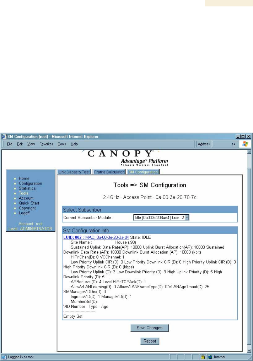
27.6 USING THE SM CONFIGURATION TOOL (AP, BHM)
The SM Configuration tab in the Tools page of the AP or BHM displays
◦ the current values whose control may be subject to the setting in the
Configuration Source parameter.
◦ an indicator of the source for each value.
An example of the SM Configuration tab is displayed in Figure 163.
Figure 163: SM Configuration tab of AP, example
Indicators for configuration source are explained under Session Status Tab of the AP on
Page 193.
Release 8 Operations Guide
Issue 2, November 2007 Draft 5 for Regulatory Review 444
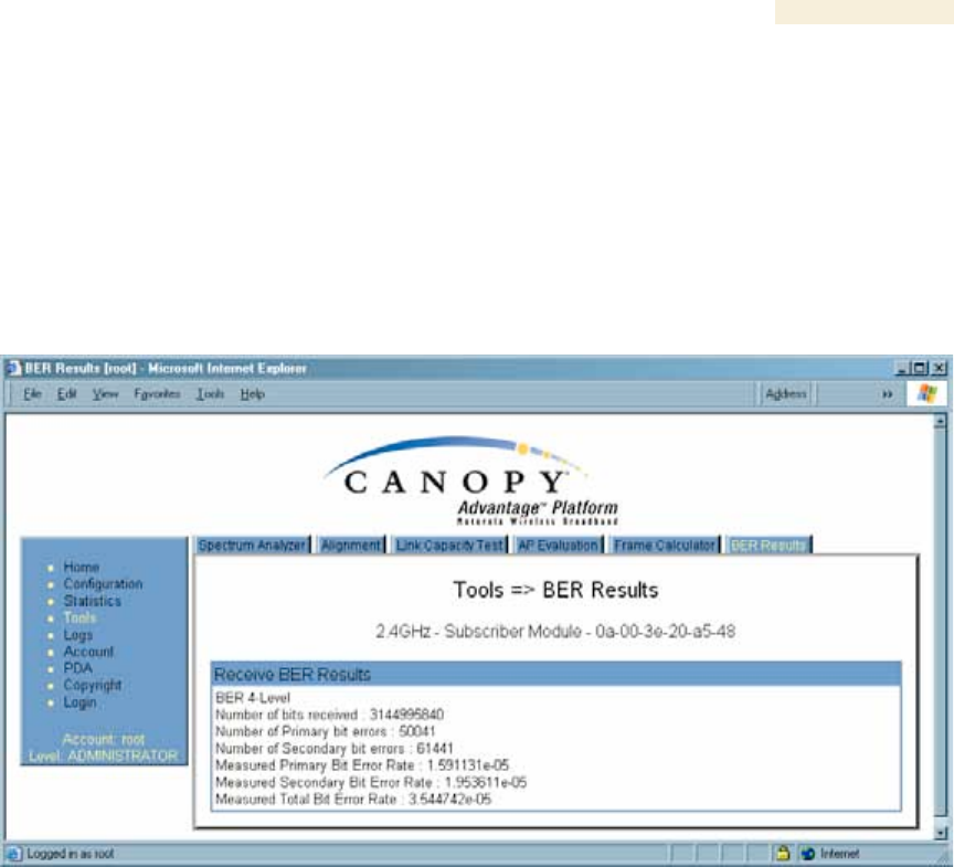
27.7 USING THE BER RESULTS TOOL (SM, BHS)
Radio BER is now supported on hardware scheduling. When looking at Radio BER data
it is important to note that it represents bit errors at the RF link level. Due to CRC checks
on fragments and packets and ARQ (Automatic Repeat reQuest), the BER of customer
data is essentially zero. Radio BER gives one indication of link quality, along with
received power level, jitter, and link tests.
BER is only instrumented on the downlink, and can be read on each SM’s Tools>BER
Results page. Each time the tab is clicked, the current results are read, and counters are
reset to zero. An example of the BER Results tab is displayed in Figure 164.
Figure 164: BER Results tab of SM, example
The BER Results tab can be helpful in troubleshooting poor link performance. The value
in the Measured Total Bit Error Rate field represents the bit error rate (BER) in the RF
link since the last time the BER Results tab was clicked.
The link is acceptable if the value of this field is less than 10−4. If the BER is greater than
10−4, re-evaluate the installation of both modules in the link.
The BER test signal is only broadcast by the AP (and compared to the expected test
signal by the SM) when capacity in the sector allows it – it is the lowest priority for AP
transmissions.

Release 8 Operations Guide
Issue 2, November 2007 Draft 5 for Regulatory Review 445
28 MAINTAINING YOUR CANOPY SOFTWARE
Canopy provides release compatibility information and caveats about each release.
28.1 HISTORY OF SYSTEM SOFTWARE UPGRADES
28.1.1 Canopy Release 8 Features
Canopy Release 8 introduces the following new features:
◦ Scheduling Limited to Hardware Scheduler
◦ Tiered Permissions and User Accounts
◦ GUI Customizable via CSS
◦ Links to SM GUI via Session Status and Remote Subscribers Tabs of AP
◦ Dynamic Frequency Selection (DFS) v1.2.3 in All 5.4- and 5.7-GHz Modules
◦ Bit Error Rate (BER) Display with Hardware Scheduler
◦ AP SNMP Proxy to SMs
◦ Translation Bridging (MAC Address Mapping)
◦ SM Isolation
◦ Management Access Filtering for SM
◦ Source IP Management Access for AP and SM
◦ Optional DHCP Configuration of Management Interface
28.1.2 Canopy Release 8 Fixes
Canopy Release 8 includes the following fixes:
◦ Management Web (http) Access Lockup Fix
◦ Enforcement of Ethernet Link Speed Setting
◦ MIBs Support Only Applicable Objects
28.2 HISTORY OF CMMmicro SOFTWARE UPGRADES
◦ Canopy currently supports CMMmicro Releases up through Release 2.2.
28.3 TYPICAL CONTENTS OF RELEASE NOTES
Canopy supports each release with software release notes, which include
◦ description of features that are introduced in the new release.
◦ issues that the new release resolves.
◦ known issues and special notes for the new release.
◦ installation procedures for the new release.
28.4 TYPICAL UPGRADE PROCESS
In a typical upgrade process, proceed as follows:
1. Visit the software page of the Canopy web site.
2. Read the compatibility information and any caveats that Canopy associates with
the release.

Release 8 Operations Guide
Issue 2, November 2007 Draft 5 for Regulatory Review 446
3. Read the software release notes from the web site.
4. On the basis of these, decide whether the release is appropriate for your
network.
5. Download the software release and associated files.
6. Use CNUT to manage the upgrade across your network.
28.4.1 Downloading Software and Release Notes
All supported software releases, the associated software release notes document, and
updated MIB files are available for download at any time from
http://motorola.motorola.com/canopy/support/software/. This web site also typically
provides a summary of the backward compatibility and any advantages or disadvantages
of implementing the release.
When you click on the release that you wish to download, you are prompted for
information that identifies yourself and your organization (such as name, address, and
e-mail address). When you complete and submit the form that prompts for this
information, the download is made available to you.

Release 8 Operations Guide
Issue 2, November 2007 Draft 5 for Regulatory Review 447
29 REBRANDING MODULE INTERFACE SCREENS
Distinctive fonts indicate
literal user input.
variable user input.
literal system responses.
variable system responses.
The interface screens on each module display the Canopy or Canopy Advantage logo.
These logos can be replaced with other logos using Procedure 42.
The logo is a hyperlink and clicking on it takes the user to the Canopy web site.
A different site (perhaps the operator’s support site) can be made the destination using
Procedure 43.
To return a module to regular logos and hyperlinks, use Procedure 44.
The logo at the top of each page is a key indicator to the user whether a module is
Canopy or Canopy Advantage. If you choose to replace the Canopy logos, use two
noticeably different logos so that users can continue to easily distinguish between a
Canopy module and a Canopy Advantage module.
To replace logos and hyperlinks efficiently throughout your network, read the following
two procedures, write a script, and execute your script through the Canopy Network
Updater Tool (CNUT).7 To replace them individually, use one of the following two
procedures.
Procedure 42: Replacing the Canopy logo on the GUI with another logo
1. If the current logo is the Canopy logo, name your custom logo file on your
computer canopy.jpg and put it in your home directory.
If the current logo is the Canopy Advantage logo, name your custom logo file on
your computer advantaged.jpg and put it in your home directory.
2. Use an FTP (File Transfer Protocol) session to transfer this file to the module, as
in the example session shown in Figure 165.
7 See Using the Canopy Network Updater Tool (CNUT) on Page 407.

Release 8 Operations Guide
Issue 2, November 2007 Draft 5 for Regulatory Review 448
> ftp ModuleIPAddress
Connected to ModuleIPAddress
220 FTP server ready
Name (ModuleIPAddress:none): root
331 Guest login ok
Password: <password-if-configured>
230 Guest login ok, access restrictions apply.
ftp> binary
200 Type set to I
ftp> put canopy.jpg
OR
put advantaged.jpg
OR
put top.html
ftp> quit
221 Goodbye
Figure 165: Example ftp session to transfer custom logo file
3. Use a telnet session and the addwebfile command to add the new file to the
file system, as in the example session shown in Figure 166.
NOTE:
Supported telnet commands execute the following results:
◦ addwebfile adds a custom logo file to the file system.
◦ clearwebfile clears the logo file from the file system.
◦ lsweb lists the custom logo file and display the storage
space available on the file system.

Release 8 Operations Guide
Issue 2, November 2007 Draft 5 for Regulatory Review 449
>telnet ModuleIPAddress
/---------\
C A N O P Y
Motorola Broadband Wireless Technology Center
(Copyright 2001, 2002 Motorola Inc.)
Login: root
Password: <password-if-configured>
Telnet +> addwebfile canopy.jpg
OR
addwebfile advantaged.jpg
OR
addwebfile top.html
Telnet +> lsweb
Flash Web files
/canopy.jpg 7867
free directory entries: 31
free file space: 55331
Telnet +> exit
Figure 166: Example telnet session to activate custom logo file
=========================== end of procedure ===========================
Procedure 43: Changing the URL of the logo hyperlink
1. In the editor of your choice, create a file named top.html, consisting of one
line:
<a href="myurl">
where myurl is the desired URL, for example, http://www.canopywireless.com.
2. Save and close the file as top.html.
3. Use an FTP (File Transfer Protocol) session to transfer this file to the module, as
in the example session shown in Figure 165 on Page 448.
4. Use a telnet session and the addwebfile command to add the new file (top.html)
to the file system, as in the example session shown in Figure 166.
=========================== end of procedure ===========================
If you ever want to restore the original logo and hyperlink in a module, perform the
following steps.
Procedure 44: Returning a module to its original logo and hyperlink
1. Use a telnet session and the clearwebfile command to clear all custom files from
the file system of the module, as in the example session shown in Figure 167
below.

Release 8 Operations Guide
Issue 2, November 2007 Draft 5 for Regulatory Review 450
>telnet ModuleIPAddress
/---------\
C A N O P Y
Motorola Broadband Wireless Technology
Center
(Copyright 2001, 2002 Motorola Inc.)
Login: root
Password: <password-if-configured>
Telnet +> lsweb
Flash Web files
canopy.jpg 7867
free directory entries: 31
free file space: 56468
Telnet +> clearwebfile
Telnet +> lsweb
Flash Web files
free directory entries: 32
free file space 64336 bytes
Telnet +> exit
Figure 167: Example telnet session to clear custom files
=========================== end of procedure ======================

Release 8 Operations Guide
Issue 2, November 2007 Draft 5 for Regulatory Review 451
30 TOGGLING REMOTE ACCESS CAPABILITY
Based on your priorities for additional security and ease of network administration, you
can deny or permit remote access individually to any AP, SM, or BH.
30.1 DENYING ALL REMOTE ACCESS
Wherever the No Remote Access feature is enabled by the following procedure, physical
access to the module is required for
◦ any change in the configuration of the module.
◦ any software upgrade in the module.
Where additional security is more important that ease of network administration, you can
disable all remote access to a module as follows.
Procedure 45: Denying all remote access
1. Insert the override plug into the RJ-11 GPS utility port of the module.
2. Power up or power cycle the module.
3. Access the web page http://169.254.1.1/lockconfig.html.
4. Click the check box.
5. Save the changes.
6. Reboot the module.
7. Remove the override plug.
RESULT: No access to this module is possible through HTTP, SNMP, FTP,
telnet, or over an RF link.
=========================== end of procedure ======================
30.2 REINSTATING REMOTE ACCESS CAPABILITY
Where ease of network administration is more important than the additional security that
the No Remote Access feature provides, this feature can be disabled as follows:
Procedure 46: Reinstating remote access capability
1. Insert the override plug into the RJ-11 GPS utility port of the module.
2. Power up or power cycle the module.
3. Access the web page http://169.254.1.1/lockconfig.html.
4. Click the check box to uncheck the field.
5. Save the changes.
6. Reboot the module.
7. Remove the override plug.
RESULT: Access to this module is possible through HTTP, SNMP, FTP, telnet,
or over an RF link.
=========================== end of procedure ======================
Release 8 Operations Guide
Issue 2, November 2007 Draft 5 for Regulatory Review 453
31 SETTING UP A PROTOCOL ANALYZER ON YOUR
CANOPY NETWORK
Selection of protocol analyzer software and location for a protocol analyzer depend on
both the network topology and the type of traffic to capture. However, the examples in
this section are based on free-of-charge Ethereal software, which is available at
http://ethereal.com/.
The equipment required to set up a protocol analyzer includes:
◦ 1 hub
◦ 1 laptop computer with protocol analyzer software installed
◦ 2 straight-through Ethernet cables
◦ 1 Canopy power converter (ACPS110)
31.1 ANALYZING TRAFFIC AT AN SM
The IP address of the protocol analyzer laptop computer must match the IP addressing
scheme of the SM. If the SM has DHCP enabled, then configure the laptop computer to
automatically obtain an address. If DHCP is not enabled, then ensure that the laptop
computer is configured with a static IP address in the same subnet as the SM.
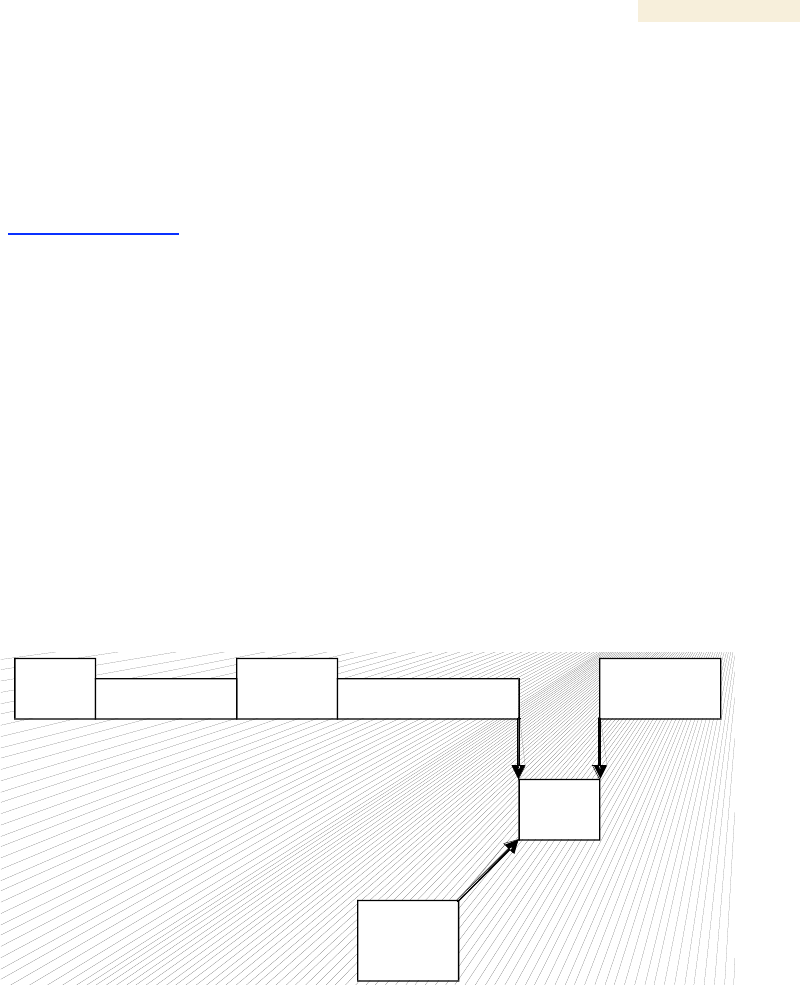
The configuration for analyzing traffic at an SM is shown in Figure 168.
Subscriber
PC
Power
Supply
SM
HUB
Sniffer
Laptop
To Computer Cable
To Radio Cable
Figure 168: Protocol analysis at SM
Release 8 Operations Guide
Issue 2, November 2007 Draft 5 for Regulatory Review 454
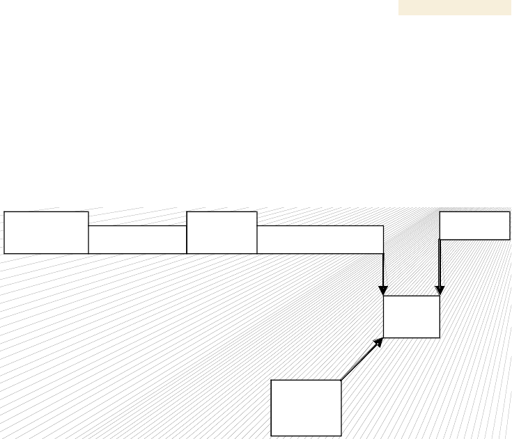
31.2 ANALYZING TRAFFIC AT AN AP OR BH WITH NO CMM
The IP address of the protocol analyzer laptop computer must match the IP addressing
scheme of the AP/BH. If the router is configured to be a DHCP server, then configure the
laptop computer to automatically obtain an address. If DHCP is not enabled, then ensure
that the laptop computer is configured with a static IP address in the same subnet as the
AP/BH.
The configuration for analyzing traffic at an AP or BH that is not connected to a CMM is
shown in Figure 169.
Router
Power
Supply
AP or BH
HUB
Sniffer
Laptop
To Computer Cable
To Radio Cable
Figure 169: Protocol analysis at AP or BH not connected to a CMM
31.3 ANALYZING TRAFFIC AT AN AP OR BH WITH A CMM
The IP address of the protocol analyzer laptop computer must match the IP addressing
scheme of the AP/BH. If the router is configured to be a DHCP server, then configure the
laptop computer to automatically obtain an address. If DHCP is not enabled, ensure that
the laptop computer is configured with a static IP address in the same subnet as the
AP/BH.
Connect the hub to the J2 Ethernet to Switch of the port that is associated with the
AP/BH. This example is of capturing traffic from AP/BH 111, which is connected to
Port 1. The configuration for analyzing traffic at an AP or BH that is connected to a CMM
is shown in Figure 170.
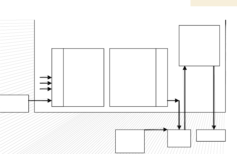
Release 8 Operations Guide
Issue 2, November 2007 Draft 5 for Regulatory Review 455
CMM
Route r
AP/BH
111
HUB
Sniffer
Laptop
J2 Ethernet to
Switch
J1 to Radio
8
7
6
5
4
3
2
1
8
7
6
5
4
3
2
1
Ethernet Switch
Figure 170: Protocol analysis at AP or BH connected to a CMM
31.4 EXAMPLE OF A PROTOCOL ANALYZER SETUP FOR AN SM
The following is an example of a network protocol analyzer setup using Ethereal®
software to capture traffic at the SM level. The Ethereal network protocol analyzer has
changed its name to Wireshark™, but functionality and use remains much the same. This
example is based on the following assumptions:
◦ All required physical cabling has been completed.
◦ The hub, protocol analyzer laptop computer, and subscriber PC are successfully
connected.
◦ The SM is connected
− as shown in Figure 169 on Page 454.
− to the subscriber PC and the AP.
◦ Ethereal software is operational on the laptop computer.
Although these procedures involve the SM, the only difference in the procedure for
analyzing traffic on an AP or BH is the hub insertion point.
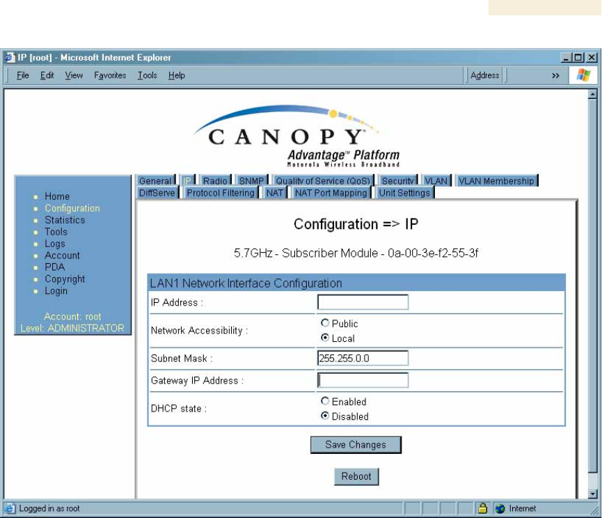
The IP Configuration screen of the example SM is shown in Figure 171.
Release 8 Operations Guide
Issue 2, November 2007 Draft 5 for Regulatory Review 456
Figure 171: IP tab of SM with NAT disabled and local accessibility
Procedure 47: Setting up a protocol analyzer
1. Note the IP configuration of the SM.
2. Browse to StartMy Network PlacesNetwork and Dialup Connections.
3. For Local Area Connection, select Properties.
RESULT: The Local Area Connections Properties window opens, as shown in
Figure 172.
Release 8 Operations Guide
Issue 2, November 2007 Draft 5 for Regulatory Review 457
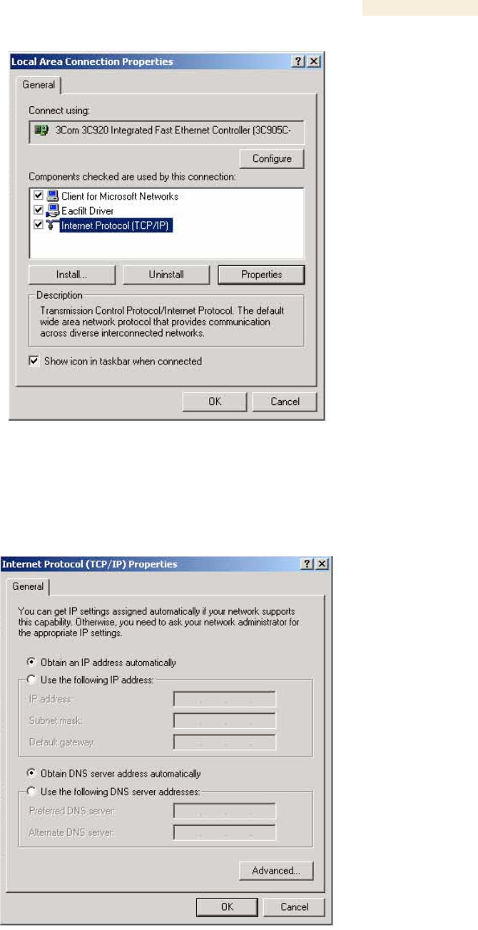
Figure 172: Local Area Connection Properties window
4. Select Internet Protocol (TCP/IP).
5. Click the Properties button.
RESULT: The Internet Protocol (TCP/IP) Properties window opens, as shown in
Figure 173.
Figure 173: Internet Protocol (TCP/IP) Properties window
Release 8 Operations Guide
Issue 2, November 2007 Draft 5 for Regulatory Review 458
6. Unless you have a static IP address configured on the SM, select
Obtain an IP address automatically for the protocol analyzer laptop computer,
as shown in Figure 173.
7. If you have configured a static IP address on the SM, then
a. select Use the following IP address.
b. enter an IP address that is in the same subnet as the SM.
8. Click OK.
9. Open your web browser.
10. Enter the IP address of the SM.
RESULT: The General Status tab of the SM opens, as shown in Figure 60 on
Page 198.
11. If the General Status tab did not open, reconfigure how the laptop computer
obtains an IP address.
12. Verify that you have connectivity from the laptop computer to the SM with the hub
inserted.
13. Launch the protocol analyzer software on the laptop computer.
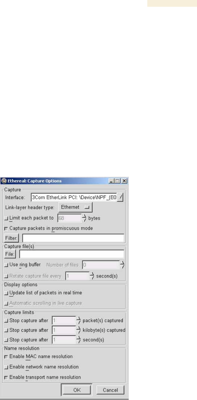
14. In the Capture menu, select Start.
RESULT: The Ethereal Capture Options window opens, as shown in Figure 174.
Figure 174: Ethereal Capture Options window
Release 8 Operations Guide
Issue 2, November 2007 Draft 5 for Regulatory Review 459
15. Ensure that the Interface field reflects the network interface card (NIC) that is
used on the protocol analyzer laptop computer.
NOTE: Although you can select filters based on specific types of traffic, all values
are defaults in this example.
16. If you wish to select filters, select them now.
17. Click OK.
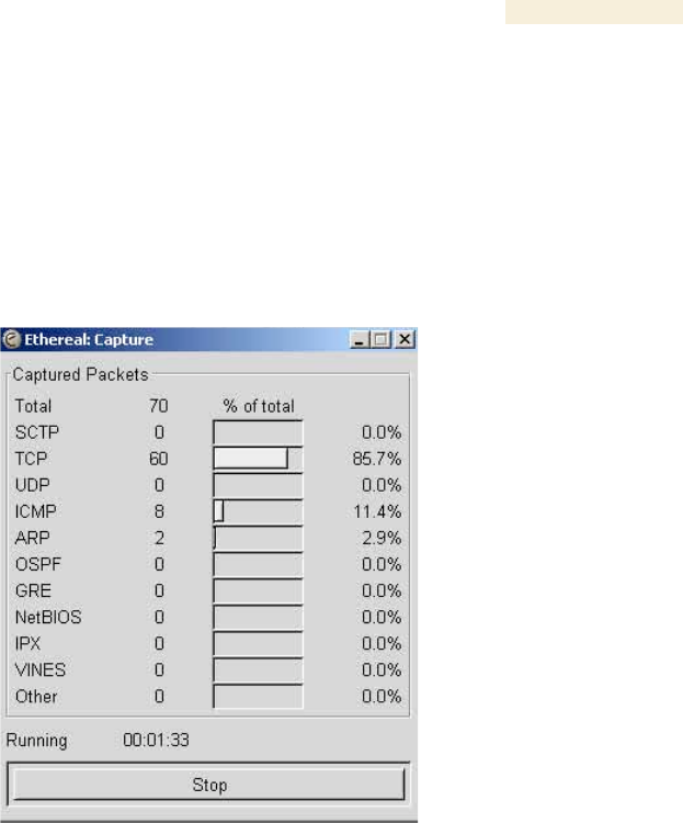
RESULT: The Ethereal Capture window opens, as shown in Figure 175.
Figure 175: Ethereal Capture window
NOTE: This window graphically displays the types of packets (by percentage)
that are being captured.
18. If all packet types are displayed with 0%, either
◦ launch your Web browser on the subscriber PC for the IP address of the SM
◦ ping the SM from the home PC.
19. If still all packet types are displayed with 0% (meaning that no traffic is being
captured), reconfigure IP addressing until you can successfully see traffic
captured on the laptop computer.
20. Whenever the desired number of packets have been captured, click Stop.
RESULT: When you stop the packet capture, the <capture> - Ethereal window
opens, as shown in Figure 176.
=========================== end of procedure ===========================
Release 8 Operations Guide
Issue 2, November 2007 Draft 5 for Regulatory Review 460
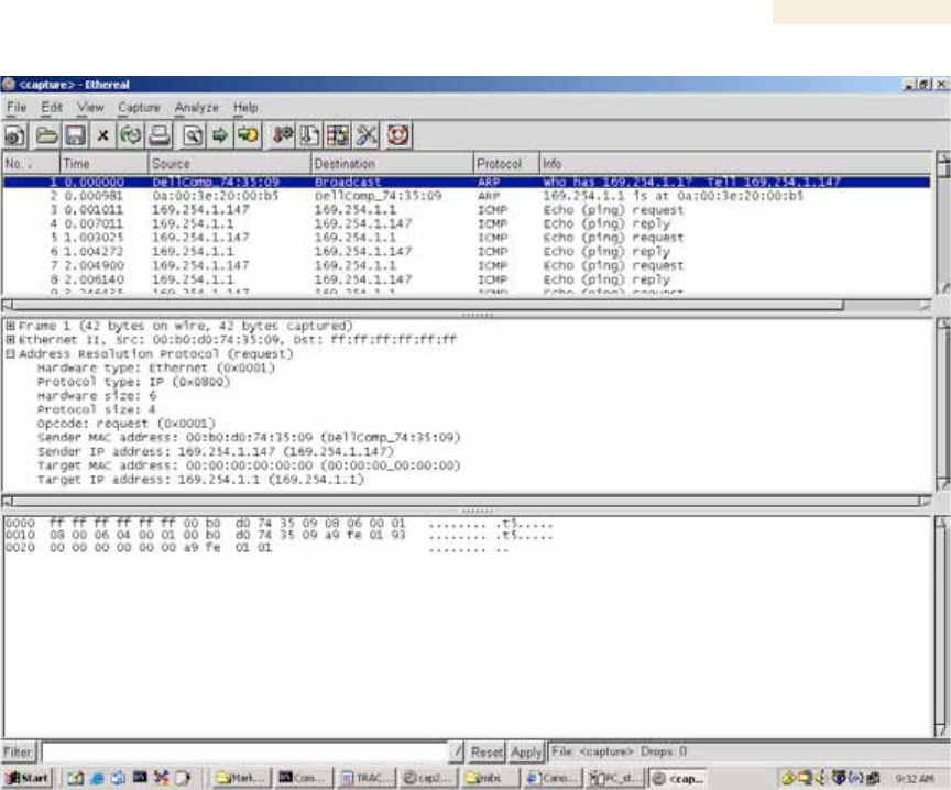
Figure 176: <capture> - Ethereal window, Packet 1 selected
This window has three panes:
◦ The top pane provides a sequenced summary of the packets captured and
includes SRC/DEST address and type of protocol. What you select in this pane
determines the additional information that is displayed in the lower two panes.
◦ The lower two panes facilitate drill-down into the packet that you selected in the
top pane.
In this example, Packet 1 (a broadcast ARP request) was selected in the top pane. The
lower two panes provide further details about Packet 1.
Another example is shown in Figure 177.
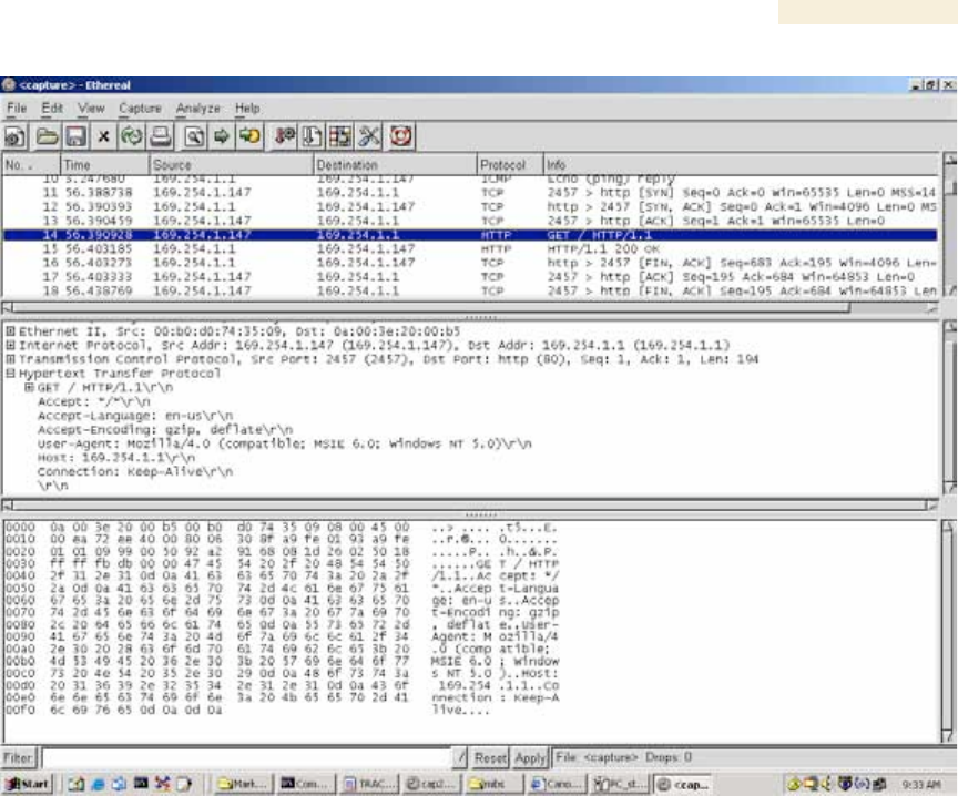
Release 8 Operations Guide
Issue 2, November 2007 Draft 5 for Regulatory Review 461
Figure 177: <capture> - Ethereal window, Packet 14 selected
In this second example, Packet 14 (protocol type HTTP) is selected in the top pane.
The two lower panes provide further details about Packet 14.

Release 8 Operations Guide
Issue 2, November 2007 Draft 5 for Regulatory Review 463
32 TROUBLESHOOTING
32.1 GENERAL PLANNING FOR TROUBLESHOOTING
Effective troubleshooting depends in part on measures that you take before you
experience trouble in your network. Canopy recommends the following measures for
each site:
1. Identify troubleshooting tools that are available at your site (such as a protocol
analyzer).
2. Identify commands and other sources that can capture baseline data for the site.
These may include
◦ ping
◦ tracert or traceroute
◦ Link Capacity Test results
◦ throughput data
◦ Configuration tab captures
◦ Status tab captures
◦ session logs
3. Start a log for the site.
4. Include the following information in the log:
◦ operating procedures
◦ site-specific configuration records
◦ network topology
◦ software releases, boot versions, and FPGA firmware versions
◦ types of hardware deployed
◦ site-specific troubleshooting processes
◦ escalation procedures
5. Capture baseline data into the log from the sources listed in Step 2.
32.2 GENERAL FAULT ISOLATION PROCESS
Effective troubleshooting also requires an effective fault isolation methodology that
includes
◦ attempting to isolate the problem to the level of a system, subsystem, or link,
such as
− AP to SM
− AP to CMM
− AP to GPS
− CMM to GPS
− BHM to BHS
− BHM to CMM
− power
◦ researching Event Logs of the involved equipment. (See Interpreting Messages
in the Event Log on Page 410.)

Release 8 Operations Guide
Issue 2, November 2007 Draft 5 for Regulatory Review 464
◦ answering the questions listed in the following section.
◦ reversing the last previous corrective attempt before proceeding to the next.
◦ performing only one corrective attempt at a time.
32.3 QUESTIONS TO HELP ISOLATE THE PROBLEM
When a problem occurs, attempt to answer the following questions:
1. What is the history of the problem?
◦ Have we changed something recently?
◦ Have we seen other symptoms before this?
2. How wide-spread is the symptom?
◦ Is the problem on only a single SM? (If so, focus on that SM.)
◦ Is the problem on multiple SMs? If so
− is the problem on one AP in the cluster? (If so, focus on that AP)
− is the problem on multiple, but not all, APs in the cluster? (If so, focus on
those APs)
− is the problem on all APs in the cluster? (If so, focus on the CMM and the
GPS signal.)
3. Based on data in the Event Log (described in Interpreting Messages in the Event
Log on Page 410)
◦ does the problem correlate to External Hard Resets with no WatchDog timers?
(If so, this indicates a loss of power. Correct your power problem.)
◦ is intermittent connectivity indicated? (If so, verify your configuration, power
level, jitter, cables and connections, and the speed duplex of both ends of the
link).
◦ does the problem correlate to loss-of-sync events?
4. Are connections made via shielded cables?
5. Does the GPS antenna have an unobstructed view of the entire horizon?
32.4 SECONDARY STEPS
After preliminary fault isolation through the above steps
1. check the Canopy knowledge base
(http://motorola.canopywireless.com/support/knowledge) to find whether other
network operators have encountered a similar problem.
2. proceed to any appropriate set of diagnostic steps. These are organized as
follows:
◦ Module Has Lost or Does Not Establish Connectivity
◦ NAT/DHCP-configured SM Has Lost or Does Not Establish Connectivity on
Page 466
◦ SM Does Not Register to an AP on Page 468
◦ BHS Does Not Register to the BHM on Page 469
◦ Module Has Lost or Does Not Gain Sync on Page 470
◦ Module Does Not Establish Ethernet Connectivity on Page 471
◦ Module Does Not Power Up on Page 472
◦ Power Supply Does Not Produce Power on Page 472

Release 8 Operations Guide
Issue 2, November 2007 Draft 5 for Regulatory Review 465
◦ CMM2 Does Not Power Up on Page 473
◦ CMM2 Does Not Pass Proper GPS Sync to Connected Modules on
Page 473
32.5 PROCEDURES FOR TROUBLESHOOTING
32.5.1 Module Has Lost or Does Not Establish Connectivity
To troubleshoot a loss of connectivity, perform the following steps.
Procedure 48: Troubleshooting loss of connectivity
1. Isolate the end user/SM from peripheral equipment and variables such as
routers, switches, and firewalls.
2. Set up the minimal amount of equipment.
3. On each end of the link
a. check the cables and connections.
b. verify that the cable/connection scheme—straight-through or crossover—is
correct.
c. verify that the LED labeled LNK is green.
d. access the General Status tab in the Home page of the module.
e. verify that the SM is registered.
f. verify that RSSI is 700 or higher.
g. verify that jitter is reported as 9 or lower.
h. access the IP tab in the Configuration page of the module.
i. verify that IP addresses match and are in the same subnet.
4. On the SM end of the link
a. verify that the PC that is connected to the SM is correctly configured to obtain
an IP address through DHCP.
b. execute ipconfig.
c. verify that the PC has an assigned IP address.
5. On each end of the link
a. access the General tab in the Configuration page of each module.
b. verify that the setting for Link Speeds (or negotiation) matches that of the
other module.
c. access the Radio tab in the Configuration page of each module.
d. verify that the Radio Frequency Carrier setting is checked in the Custom
Radio Frequency Scan Selection List.
e. verify that the Color Code setting matches that of the other module.
f. access the browser LAN settings (for example, at
ToolsInternet OptionsConnectionsLAN Settings in Internet
Explorer).
g. verify that none of the settings are selected.
h. access the Link Capacity Test tab in the Tools page of the module.
i. perform a link test. (See Procedure 40: Performing a Link Capacity Test on
Page 433.)

Release 8 Operations Guide
Issue 2, November 2007 Draft 5 for Regulatory Review 466
j. verify that the link test results show efficiency greater than 90% in both the
uplink and downlink (except as described under Comparing Efficiency in 1X
Operation to Efficiency in 2X Operation on Page 135).
k. execute ping.
l. verify that no packet loss was experienced.
m. verify that response times are not significantly greater than
◦ 2.5 ms from BH to BH
◦ 4 ms from AP to SM
◦ 15 ms from SM to AP
n. replace any cables that you suspect may be causing the problem.
6. After connectivity has been re-established, reinstall network elements and
variables that you removed in Step 1.
=========================== end of procedure ===========================
32.5.2 NAT/DHCP-configured SM Has Lost or Does Not Establish Connectivity
Before troubleshooting this problem, identify the NAT/DHCP configuration from the
following list:
◦ NAT with DHCP Client and DHCP Server
◦ NAT with DHCP Client
◦ NAT with DHCP Server
◦ NAT without DHCP
To troubleshoot a loss of connectivity for an SM configured for NAT/DHCP, perform the
following steps.
Procedure 49: Troubleshooting loss of connectivity for NAT/DHCP-configured SM
1. Isolate the end user/SM from peripheral equipment and variables such as
routers, switches, and firewalls.
2. Set up the minimal amount of equipment.
3. On each end of the link
a. check the cables and connections.
b. verify that the cable/connection scheme—straight-through or crossover—is
correct.
c. verify that the LED labeled LNK is green.
4. At the SM
a. access the NAT Table tab in the Logs web page.
NOTE: An example of this tab is shown in Figure 178.
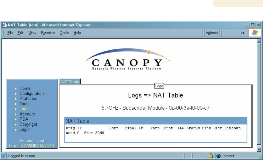
Release 8 Operations Guide
Issue 2, November 2007 Draft 5 for Regulatory Review 467
Figure 178: NAT Table tab of SM, example
b. verify that the correct NAT translations are listed.
RESULT: NAT is eliminated as a possible cause if these translations are
correct.
5. If this SM is configured for NAT with DHCP, then at the SM
a. execute ipconfig.
b. verify that the PC has an assigned IP address.
c. if the PC does not have an assigned IP address, then
◦ enter ipconfig /release “Adapter Name”.
◦ enter ipconfig /renew “Adapter Name”.
◦ reboot the PC.
◦ retreat to Step 5a.
d. if the PC has an assigned IP address, then
◦ access the NAT DHCP Statistics tab in the Statistics web page of
the SM.
NOTE: An example of this tab is shown in Figure 179.
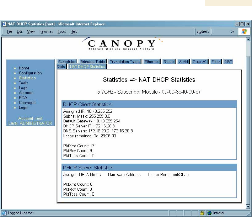
Release 8 Operations Guide
Issue 2, November 2007 Draft 5 for Regulatory Review 468
Figure 179: NAT DHCP Statistics tab of SM, example
◦ verify that DHCP is operating as configured.
6. After connectivity has been re-established, reinstall network elements and
variables that you removed in Step 1.
=========================== end of procedure ======================
32.5.3 SM Does Not Register to an AP
To troubleshoot an SM failing to register to an AP, perform the following steps.
Procedure 50: Troubleshooting SM failing to register to an AP
1. Access the Radio tab in the Configuration page of the SM.
2. Note the Color Code of the SM.
3. Access the Radio tab in the Configuration page of the AP.
4. Verify that the Color Code of the AP matches that of the SM.
5. Note the Radio Frequency Carrier of the AP.
6. Verify that the value of the RF Frequency Carrier of the AP is selected in the
Custom Radio Frequency Scan Selection List parameter in the SM.

Release 8 Operations Guide
Issue 2, November 2007 Draft 5 for Regulatory Review 469
7. In the AP, verify that the Max Range parameter is set to a distance slightly
greater than the distance between the AP and the furthest SM that must register
to this AP.
8. Verify that a clear line of sight exists between the AP and the SM, and that no
obstruction significantly penetrates the Fresnel zone of the attempted link.
If these conditions are not established, then verify that the AP and SM are
900-MHz modules in close proximity to each other.
9. Access the General Status tab in the Home page of each module.
10. In the Software Version field, verify that both the AP and SM are of the same
encryption scheme (AES or DES).
11. Remove the bottom cover of the SM to expose the LEDs.
12. Power cycle the SM.
RESULT: Approximately 25 seconds after the power cycle, the green LED
labeled LNK should light to indicate that the link has been established. If the
orange LED labeled SYN is lit instead, then the SM is in Alignment mode
because the SM failed to establish the link.
13. In this latter case, and if the SM has encountered no customer-inflicted damage,
then request an RMA for the SM.
=========================== end of procedure ======================
32.5.4 BHS Does Not Register to the BHM
To troubleshoot an BHS failing to register to the BHM, perform the following steps.
Procedure 51: Troubleshooting BHS failing to register to a BHM
1. Access the Radio tab in the Configuration page of the BHS.
2. Note the Color Code of the BHS.
3. Access the Radio tab in the Configuration page of the BHM.
4. Verify that the Color Code of the BHM matches that of the BHS.
5. Note the Radio Frequency Carrier of the BHM.
6. Verify that the value of the RF Frequency Carrier of the BHM is selected in the
Custom Radio Frequency Scan Selection List parameter on the Configuration
page of the BHS.
7. Verify that a clear line of sight exists between the BHM and BHS, and that no
obstruction significantly penetrates the Fresnel zone of the attempted link.
8. Access the General Status tab in the Home page of each module.
9. In the Software Version field, verify that both the BHM and BHS are of the same
encryption scheme (AES or DES).
10. Also in the Software Version field, verify that both the BHM and BHS are of the
same modulation rate from the factory (BH20 or BH10).
11. Remove the bottom cover of the BHS to expose the LEDs.
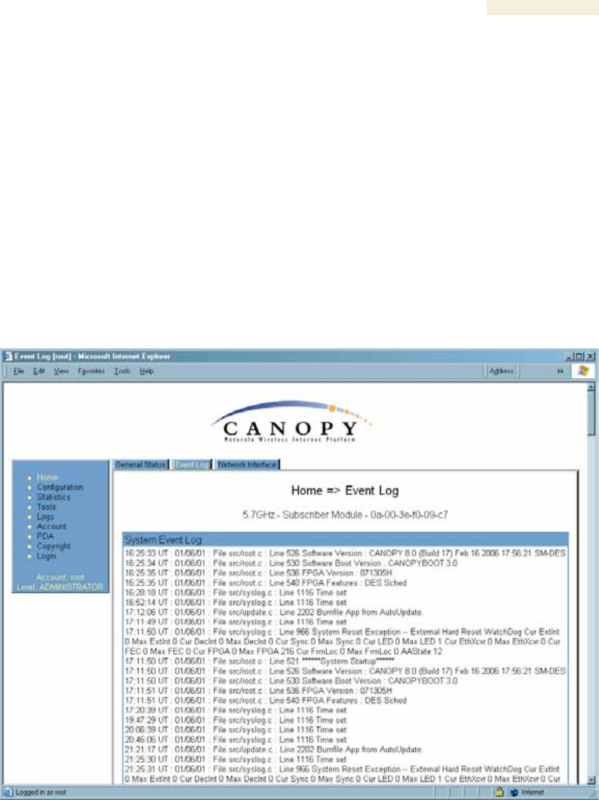
Release 8 Operations Guide
Issue 2, November 2007 Draft 5 for Regulatory Review 470
12. Power cycle the BHS.
RESULT: Approximately 25 seconds after the power cycle, the green LED
labeled LNK should light to indicate that the link has been established. If the
orange LED labeled SYN is lit instead, then the BHS is in Alignment mode
because the BHS failed to establish the link. In this latter case, and if the BHS
has encountered no customer-inflicted damage, then request an RMA for
the BHS.
=========================== end of procedure ======================
32.5.5 Module Has Lost or Does Not Gain Sync
To troubleshoot a loss of sync, perform the following steps.
Procedure 52: Troubleshooting loss of sync
1. Access the Event Log tab in the Home page of the SM.
NOTE: An example of this tab is shown in Figure 180.
Figure 180: Event Log tab of SM, example
2. Check for messages with the following format:
RcvFrmNum =
ExpFrmNum =
(See Table 64: Event Log messages for abnormal events on Page 412.)

Release 8 Operations Guide
Issue 2, November 2007 Draft 5 for Regulatory Review 471
3. If these messages are present, check the Event Log tab of another SM that is
registered to the same AP for messages of the same type.
4. If the Event Log of this second SM does not contain these messages, then the
fault is isolated to the first SM.
5. If the Event Log page of this second SM contains these messages, access the
GPS Status page of the AP.
6. If the Satellites Tracked field in the GPS Status page of the AP indicates fewer
than 4 or the Pulse Status field does not indicate Generating Sync, check the
GPS Status page of another AP in the same AP cluster for these indicators.
7. If these indicators are present in the second AP
a. verify that the GPS antenna still has an unobstructed view of the entire
horizon.
b. visually inspect the cable and connections between the GPS antenna and
the CMM.
c. if this cable is not shielded, replace the cable with shielded cable.
8. If these indicators are not present in the second AP
a. visually inspect the cable and connections between the CMM and the AP
antenna.
b. if this cable is not shielded, replace the cable with shielded cable.
=========================== end of procedure ===========================
32.5.6 Module Does Not Establish Ethernet Connectivity
To troubleshoot a loss of Ethernet connectivity, perform the following steps.
Procedure 53: Troubleshooting loss of Ethernet connectivity
1. Verify that the connector crimps on the Ethernet cable are not loose.
2. Verify that the Ethernet cable is not damaged.
3. If the Ethernet cable connects the module to a network interface card (NIC),
verify that the cable is pinned out as a straight-through cable.
4. If the Ethernet cable connects the module to a hub, switch, or router, verify that
the cable is pinned out as a crossover cable.
5. Verify that the Ethernet port to which the cable connects the module is set to
auto-negotiate speed.
6. Power cycle the module.
RESULT: Approximately 25 seconds after the power cycle, the green LED
labeled LNK should light to indicate that the link has been established. If the
orange LED labeled SYN is lit instead, then the module is in Alignment mode
because the module failed to establish the link.
7. In this latter case, and if the module has encountered no customer-inflicted
damage, then request an RMA for the module.
=========================== end of procedure ===========================
Release 8 Operations Guide
Issue 2, November 2007 Draft 5 for Regulatory Review 472
32.5.7 Module Does Not Power Up
To troubleshoot the failure of a module to power up, perform the following steps.
Procedure 54: Troubleshooting failure to power up
1. Verify that the connector crimps on the Ethernet cable are not loose.
2. Verify that the Ethernet cable is not damaged.
3. Verify that the cable is wired and pinned out according to the specifications
provided under Wiring Connectors on Page 182.
4. Remove the cover of the module to expose the components on the printed wiring
board.
5. Find the Ethernet transformer, which is labeled with either the name Halo or the
name Pulse.
6. Verify that the Ethernet transformer does not show damage that would have
been caused by improper cabling. (You can recognize damage as the top of the
transformer being no longer smooth. The transformer in the following picture is
damaged and is ineligible for an RMA.)
7. Connect the power supply to a known good Canopy module via a known good
Ethernet cable.
8. Attempt to power up the known good module and
◦ if the known good module fails to power up, request an RMA for the power
supply.
◦ if the known good module powers up, return to the module that does not power
up.
9. Reconnect the power supply to the failing module.
10. Connect the power supply to a power source.
11. Verify that the red LED labeled PWR lights.
12. If this LED does not light, and the module has not been powered up since the last
previous FPGA firmware upgrade was performed on the module, then request an
RMA for the module.
=========================== end of procedure ===========================
32.5.8 Power Supply Does Not Produce Power
To troubleshoot the failure of a power supply to produce power, perform the following
steps.
Procedure 55: Troubleshooting failure of power supply to produce power
1. Verify that the connector crimps on the Ethernet cable are not loose.
2. Verify that the Ethernet cable is not damaged.

Release 8 Operations Guide
Issue 2, November 2007 Draft 5 for Regulatory Review 473
3. Verify that the cable is wired and pinned out according to the specifications
provided under Wiring Connectors on Page 182.
4. Connect the power supply to a known good Canopy module via a known good
Ethernet cable.
5. Attempt to power up the known good module.
6. If the known good module fails to power up, request an RMA for the power
supply.
=========================== end of procedure ===========================
32.5.9 CMM2 Does Not Power Up
To troubleshoot a malfunctioning CMM2, perform the following steps.
Procedure 56: Troubleshooting CMM2 that malfunctions
1. Verify that the 115-/230-V switch (in the lower right-hand corner of the CMM2) is
in the correct position for the power source. (See Figure 123 on Page 337.)
Applying power when this switch is in the wrong position can damage the CMM2
and will render it ineligible for an RMA.
2. Verify that the electrical source to the CMM2 meets Canopy specifications. See
Table 18 on Page 71.
3. Verify that the electrical source is connected to the CMM2 at the proper
connection point. (See Figure 125 on Page 339.)
4. Verify that the fuse is operational.
5. Verify that the fuse is properly seated in the receptacle.
6. Attempt to power up the CMM2.
7. If the power indicator on the interconnect board of the CMM2 fails to light when
power is applied to the CMM2, request an RMA for the CMM2.
=========================== end of procedure ======================
32.5.10 CMM2 Does Not Pass Proper GPS Sync to Connected Modules
If the Event Log tabs in all connected modules contain Loss of GPS Sync Pulse
messages, perform the following steps.
Procedure 57: Troubleshooting CMM2 not passing sync
1. Verify that the GPS antenna has an unobstructed view of the entire horizon.
2. Verify that the GPS coaxial cable meets specifications.
3. Verify that the GPS sync cable meets specifications for wiring and length.
4. If the web pages of connected modules indicate any of the following, then find
and eliminate the source of noise that is being coupled into the GPS sync cable:
◦ In the GPS Status page
− anomalous number of Satellites Tracked (greater than 12, for example)
− incorrect reported Latitude and/or Longitude of the antenna
◦ In the Event Log page
− garbled GPS messages
− large number of Acquired GPS Sync Pulse messages

Release 8 Operations Guide
Issue 2, November 2007 Draft 5 for Regulatory Review 474
5. If these efforts fail to resolve the problem, then request an RMA for the CMM2.
=========================== end of procedure ======================
32.5.11 Module Software Cannot be Upgraded
If your attempt to upgrade the software of a module fails, perform the following steps.
Procedure 58: Troubleshooting an unsuccessful software upgrade
1. Download the latest issue of the target release and the associated release notes.
2. Compare the files used in the failed attempt to the newly downloaded software.
3. Compare the procedure used in the failed attempt to the procedure in the newly
downloaded release notes.
4. If these comparisons reveal a difference, retry the upgrade, this time with the
newer file or newer procedure.
5. If, during attempts to upgrade the FPGA firmware, the following message is
repeatable, then request an RMA for the module:
Error code 6, unrecognized device
=========================== end of procedure ===========================
32.5.12 Module Functions Properly, Except Web Interface Became Inaccessible
If a module continues to pass traffic, and the telnet and SNMP interfaces to the module
continue to function, but the web interface to the module does not display, perform the
following steps.
Procedure 59: Restoring the web interface to a module
1. Enter telnet DottedIPAddress.
RESULT: A telnet session to the module is invoked.
2. At the Login prompt, enter root.
3. At the Password prompt, enter PasswordIfConfigured.
4. At the Telnet +> prompt, enter reset.
RESULT: The web interface is accessible again, and this telnet connection is
closed.
=========================== end of procedure ===========================

Release 8 Operations Guide
Issue 2, November 2007 Draft 5 for Regulatory Review 475
33 OBTAINING TECHNICAL SUPPORT
NOTE:
The contact information for Canopy Technical Support staff is included at the
end of this section (on Page 479). However, in most cases, you should follow
the procedure of this section before you contact them.
To get information or assistance as soon as possible for problems that you encounter,
use the following sequence of actions:
1. Search this document, the user guides of products that are supported by
dedicated documents, and the software release notes of supported releases
a. in the Table of Contents for the topic.
b. in the Adobe Reader® search capability for keywords that apply.8
2. Visit http://motorola.canopywireless.com/support/knowledge to view the Canopy
Knowledge Base.
3. Ask your Canopy products supplier to help.
4. View and analyze event logs, error messages, and debug messages to help
isolate the problem.
5. Check release notes and verify that all of your Canopy equipment is on the
correct software release.
6. Verify that the Canopy configuration files match the last known good (baseline)
Canopy configuration files captured in the site log book.
7. Verify connectivity (physical cabling).
8. At the SM level, minimize your network configuration (remove home network
devices to help isolate problem).
9. Perform the site verification checklist.
10. Use Table 66 (two pages) as a job aid to collect basic site information for
technical support to use.
8 Reader is a registered trademark of Adobe Systems, Incorporated.

Release 8 Operations Guide
Issue 2, November 2007 Draft 5 for Regulatory Review 476
Table 66: Basic site information for technical support
Call Log Number:
Company:
Location:
Problem Type:
Site Contact:
Site Phone:
Call Severity (Select One):
1- Urgent-Customer Svc Down
2- Serious- Customer Svc Impacted
3- Non-Critical/General Inquiry
Open Date:
Close Date:
Product Types Involved:
(ID the product type)
2400 SM/AP/BHM/BHS
5200 ER /BHM/BHS
5200 SM/AP/BHM/BHS
5700 SM/AP/BHM/BHS
1008CK
300SS
ACPS110
MAC Addresses:
IP Addresses:
Software Releases:
Boot Versions:
FPGA Versions:
Authentication ?:
Yes/No
Type:
Is the customer using
shielded cables?
Yes/No
Remote Access Method:
IP Address:

Release 8 Operations Guide
Issue 2, November 2007 Draft 5 for Regulatory Review 477
Network Scenario for this issue:
(ID those that apply)
SM to Subscriber PC
Yes/No
SM to AP (Point to Multipoint)
Yes/No
BHM to BHS (Point to Point)
Yes/No
20Meg or 10Meg backhaul
Yes/No
Link Distance:
dBm=
Jitter=
Reflectors in use:
Yes/No
NAT/DHCP Scenario:
NAT Disabled
Yes/No
NAT with DHCP Client and DHCP
Server
Yes/No
NAT with DHCP Client
Yes/No
NAT with DHCP Server
Yes/No
NAT with no DHCP
Yes/No
Problem Description:
New Install: Yes/No
NAT/DHCP Scenario:
NAT Disabled
Yes/No
NAT with DHCP Client and
DHCP
Server
Yes/No
NAT with DHCP Client
Yes/No
NAT with DHCP Server
Yes/No
NAT with no DHCP
Yes/No
11. Save your basic site information as file Site_Info.
12. From among Figure 28 on Page 103, Figure 29 on Page 104, and Figure 30 on
Page 104, select the basic network topology diagram that most closely matches
your network configuration.
13. If you selected Figure 28.
a. Indicate how many APs are in each cluster.
b. Indicate how many AP clusters are deployed (and what types).
c. Include the IP addresses.
d. Indicate the frequency for each sector.
e. Indicate the type of synchronization.
f. Indicate how much separation exists between clusters.
g. For each AP collect the following additional information:
◦ Sector number:
◦ SW release:
◦ Frequency:
◦ Color code:

Release 8 Operations Guide
Issue 2, November 2007 Draft 5 for Regulatory Review 478
◦ IP address:
◦ Downlink/uplink ratio:
◦ Max range:
◦ Bridge entry timeout:
◦ Number of subscribers:
◦ Method of synchronization:
14. If you selected Figure 29
a. Indicate how many APs are in each cluster.
b. Indicate how many AP clusters are deployed (and what types).
c. Indicate how many BH links are configured.
d. Include the IP addresses.
e. Indicate the frequency for each sector.
f. Indicate the type of synchronization.
g. Indicate how much separation exists between clusters and BHs.
h. Indicate the types of BH links (10-Mbps or 20-Mbps).
i. Distances of links.
j. Frequency used by each BH.
k. For each AP and BHM, collect the following additional information:
◦ Sector number:
◦ SW release:
◦ Frequency:
◦ Color code:
◦ IP address:
◦ Downlink/uplink ratio:
◦ Max range:
◦ Bridge entry timeout:
◦ Number of subscribers:
◦ Method of synchronization:
15. If you selected Figure 30, collect the following additional information:
◦ Sector number:
◦ SW release:
◦ Frequency:
◦ Color code:
◦ IP address:
◦ Downlink/uplink ratio:
◦ Max range:
◦ Bridge entry timeout:
◦ Number of subscribers:
◦ Method of synchronization:
16. Add any details that are not present in the generic diagram that you selected.
17. Save your diagram as file Net_Diagram.
18. Capture screens from the following web pages of affected modules:

Release 8 Operations Guide
Issue 2, November 2007 Draft 5 for Regulatory Review 479
◦ Home page Status tabs as files SM/AP/BHM/BHS_StatusTabname.gif
◦ Configuration page tabs as files SM/AP/BHM/BHS_ConfigTabname.gif
◦ Home page Event Log as file SM/AP/BHM/BHS_Events.gif
◦ Tools page Link Capacity Test tab (with link test results) as file
SM/AP/BHM/BHS_LinkTST.gif
◦ Statistics page Radio tab as file SM/AP/BHM/BHS_RFstats.gif
19. For any affected SM or BHS, capture the Tools page AP Evaluation tab as file
SM/BHS_APEval.gif.
20. For any affected SM that has NAT/DHCP enabled, capture screens from the
following additional web pages:
◦ Configuration page NAT tab as file SM_Natconfig.gif
◦ Configuration page NAT Port Mapping tab as file SM_NatPortmap.gif
◦ Logs page NAT Table tab as file SM_NatTable.gif
◦ Statistics page NAT Stats tab as file SM_NatStats.gif
◦ Statistics page Translation Table tab as file SM_ArpStats.gif
◦ Statistics page NAT DHCP Statistics tab as file SM_DhcpStats.gif
Also capture the Windows IP Configuration screen as file SM _WindowsIP.gif.
21. Escalate the problem to Canopy systems Technical Support (or another technical
support organization that has been designated for you) as follows:
a. Start e-mail to technical-support@canopywireless.com. In this email
◦ Describe the problem.
◦ Describe the history of the problem.
◦ List your attempts to solve the problem.
◦ Attach the above files.
◦ List the files that you are attaching.
b. Send the email.
c. Call 1 888 605 2552 (or +1 217 824 9742).
=========================== end of procedure ===========================

Release 8 Operations Guide
Issue 2, November 2007 Draft 5 for Regulatory Review 481
34 GETTING WARRANTY ASSISTANCE
For warranty assistance, contact your reseller or distributor for the process.

Release 8 Reference Information
Issue 2, November 2007 Draft 5 for Regulatory Review 483
R
R
RE
E
EF
F
FE
E
ER
R
RE
E
EN
N
NC
C
CE
E
E
I
I
IN
N
NF
F
FO
O
OR
R
RM
M
MA
A
AT
T
TI
I
IO
O
ON
N
N

Release 8 Reference Information
Issue 2, November 2007 Draft 5 for Regulatory Review 485
35 ADMINISTERING MODULES THROUGH TELNET
INTERFACE
In the telnet administrative interface to a module, the Canopy platform supports the
commands defined in Table 67. Many of these are not needed with CNUT.
Table 67: Supported telnet commands for module administration
Command
System help Definition
Notes
addwebfile
Add a custom web file
Syntax: addwebfile filename. Copies the
custom web file filename to non-volatile
memory.
burnfile
Burn flash from file
Syntax: burnfile filename. Updates the
CPU firmware with a new image. User the image
contained in filename if filename is
provided. If provided, filename must match
the module type (for example, SMboot.bin for
a Subscriber Module or APboot.bin for an
Access Point Module).
cat
Concatenate and display.
Syntax: cat filename. Displays the
contents of filename.
clearsyslog
Clear the system event
log
Syntax: clearsyslog. Clears the system
event log.
clearwebfile
Clear all custom web
files
Syntax: clearwebfile. Deletes all custom
web files.
exit
Exit from telnet session
Syntax: exit. Terminates the telnet interface
session.
fpga_conf
Update FPGA program
Syntax: fpga_conf. Forces a module to
perform a hard (FPGA and CPU) reset. (See
reset.)
ftp
File transfer application
Syntax: ftp. Launches the ftp client
application on the module.
help
Display command line
function help
Syntax: help. Displays a list of available telnet
commands and a brief description of each.
jbi
Update FPGA program
Syntax: jbi –aprogram file.jbc.
Updates the FPGA firmware with the new image
contained in file.jbc.
ls
List the contents of a
directory
Syntax: ls. Lists the file names of all files in the
directory.
Syntax: ls –l. Displays additional
information, such as the sizes and dates of the
files.
lsweb
List Flash Web files
Syntax: lsweb. Lists the file names of the saved
custom web files.

Release 8 Reference Information
Issue 2, November 2007 Draft 5 for Regulatory Review 486
Command
System help Definition
Notes
ping
Send ICMP ECHO_REQUEST
packets to network hosts
Syntax: ping IPaddress. Sends an ICMP
ECHO_REQUEST to IPaddress and waits
for a response. If a response is received, the
system returns IPaddress is alive.
If no response is received, the system returns no
answer from IPaddress.
reset
Reboot the unit
Syntax: reset. Forces the module to perform a
hard (FPGA and CPU) module reset. (See
fpga_conf.)
rm
Remove (unlink) files
Syntax: rm filename. Remove filename.
syslog
Display system event log:
syslog <optional
filename>
Syntax: syslog. Displays the contents of the
system log. Syntax: syslog filename. Saves
the contents of the system log to filename.
Caution: overwrites filename if it already
exists.
telnet
Telnet application
Syntax: telnet hostIPaddress. Launches
the telnet client application on the Canopy
module.
tftp
tftp application
Syntax: tftp hostIPaddress. Launches
the tftp client application on the Canopy
module.
update
Enable automatic SM code
updating
Syntax: update actionlist.txt. Enables
the automated update procedure that
actionlist.txt specifies. (Supported for
only the Access Point Module.)
updateoff
Disable automatic SM
code updating
Syntax: updateoff. Disables the
automated update procedure.
version
Display the software
version string
Syntax: version. Displays the module
version string, which contains the
software/firmware/hardware versions, the
module type, and the operating
frequency.

Release 8 Reference Information
Issue 2, November 2007 Draft 5 for Regulatory Review 487
36 REGULATORY AND LEGAL NOTICES
36.1 IMPORTANT NOTE ON MODIFICATIONS
Intentional or unintentional changes or modifications to the equipment must not be made unless
under the express consent of the party responsible for compliance. Any such modifications could
void the user’s authority to operate the equipment and will void the manufacturer’s warranty.
36.2 NATIONAL AND REGIONAL REGULATORY NOTICES
36.2.1 U.S. Federal Communication Commission (FCC) Notification
This device complies with Part 15 of the US FCC Rules and Regulations. Operation is
subject to the following two conditions: (1) This device may not cause harmful
interference, and (2) This device must accept any interference received, including
interference that may cause undesired operation.
This equipment has been tested and found to comply with the limits for a Class B digital
device, pursuant to Part 15 of the US FCC Rules. These limits are designed to provide
reasonable protection against harmful interference in a residential installation. This
equipment generates, uses, and can radiate radio-frequency energy and, if not installed
and used in accordance with these instructions, may cause harmful interference to radio
communications. If this equipment does cause harmful interference to radio or
television reception, which can be determined by turning the equipment on and off, the
user is encouraged to correct the interference by one or more of the following measures:
◦ Increase the separation between the affected equipment and the unit;
◦ Connect the affected equipment to a power outlet on a different circuit from that
which the receiver is connected to;
◦ Consult the dealer and/or experienced radio/TV technician for help.
FCC IDs and the specific configurations covered are listed in Table 68.

Release 8 Reference Information
Issue 2, November 2007 Draft 5 for Regulatory Review 488
Table 68: US FCC IDs and Industry Canada Certification Numbers and Covered
Configurations
FCC ID
Industry
Canada
Cert
Number
Frequencies
Module
Families
Antenna or
Reflector
Maximum
Transmitter
Output
Power
12 dBi Canopy
integrated
antenna
24 dBm
(250 mW)
10 dBi Maxrad
Model # Z1681,
flat panel
26 dBm
(400 mW)
10 dBi Mars
Model # MA-
IS91-T2, flat
panel
26 dBm
(400 mW)
ABZ89FC5809
109W-9000
8 MHz channels,
centered on 906-
924 MHz in 1 MHz
increments (within
the 902-928 MHz
ISM band)
900 SM,
AP
10 dBi MTI
Model #MT-
2630003/N, flat
panel
26 dBm
(400 mW)
2400 BH,
SM, AP
8 dBi internal
25 dBm
(340 mW)
ABZ89FC5808
109W-2400
20 MHz channels,
centered on 2415-
2457.5 MHz in 2.5
MHz increments
(within the 2400-
2483.5 MHz ISM
band)
2400 BH,
SM
8 dBi internal +
11 dB reflector
25 dBm
(340 mW)
5200 BH,
SM, AP
7 dBi internal
23 dBm
(200 mW)
7 dBi internal +
18 dB reflector
5 dBm
(3.2 mW)
ABZ89FC3789
109W-5200
20 MHz channels,
centered on 5275-
5325 MHz in 5 MHz
increments (within
the 5250-5350 MHz
U-NII band)
5200 BH
or SM,
only P10
Modules
7 dBi internal +
9 dB lens
14 dBm
ABZ89FC5807
109W-5210
20 MHz channels,
centered on 5275-
5325 MHz in 5 MHz
increments (within
the 5250-5350 MHz
U-NII band)
5210 BH
7 dBi internal +
18 dB reflector
5 dBm
(3.2 mW)
5400 BH,
SM, AP
7 dBi internal
23 dBm
(200 mW)
7 dBi internal +
18 dB reflector
5 dBm
(3.2 mW)
ABZ89FT7623
---
20 MHz channels,
centered on 5495-
5705 MHz in 5 MHz
increments (within
the 5470-5725 MHz
U-NII band)
5400 BH,
SM
7 dBi internal +
9 dB lens
14 dBm

Release 8 Reference Information
Issue 2, November 2007 Draft 5 for Regulatory Review 489
FCC ID
Industry
Canada
Cert
Number
Frequencies
Module
Families
Antenna or
Reflector
Maximum
Transmitter
Output
Power
5400 BH,
SM, AP
7 dBi internal
23 dBm
(200 mW)
7 dBi internal +
18 dB reflector
5 dBm
(3.2 mW)
---
109W-5400
20 MHz channels,
centered on 5495-
5575 and 5675-
5705 MHz in 5 MHz
increments (within
the 5470-5725 MHz
U-NII band with
5600-5650 MHz
excluded)
5400 BH,
SM
7 dBi internal +
9 dB lens
14 dBm
5700 BH,
SM, AP
7 dBi internal
23 dBm
(200 mW)
7 dBi internal +
18 dB reflector
23 dBm
(200 mW)
ABZ89FC5804
109W-5700
20 MHz channels,
centered on 5735-
5840 MHz in 5 MHz
increments (within
the 5725-5850
MHz ISM band)
5700 BH,
SM
7 dBi internal +
10 di lens
23 dBm
(200 mW)
5440 AP
17 dBi
connectorized
antenna (60° x
5° 3 dB beam
width)
10 dBm
ABZ89FT7629
---
10 MHz channels,
centered on 5476-
5719 in 0.5 MHz
increments (within
the 5470-5725 MHz
U-NII band)
5440 SM
17 dBi
integrated
antenna (18° x
18° 3 dB beam
width)
10 dBm
36.2.2 Industry Canada (IC) Notification
This device complies with RSS-210 of Industry Canada. Operation is subject to the
following two conditions: (1) This device may not cause harmful interference, and (2) This
device must accept any interference received, including interference that may cause
undesired operation.
Users should be cautioned to take note that in Canada high power radars are allocated
as primary users (meaning they have priority) of 5250 – 5350 MHz and 5650 – 5850 MHz
and these radars could cause interference and/or damage to license-exempt local area
networks (LELAN).
This equipment has been tested and found to comply with the limits for a Class B digital
device, pursuant to RSS-210 of Industry Canada. These limits are designed to provide
reasonable protection against harmful interference in a residential installation. This
equipment generates, uses, and can radiate radio-frequency energy and, if not installed
and used in accordance with these instructions, may cause harmful interference to radio
communications. If this equipment does cause harmful interference to radio or

Release 8 Reference Information
Issue 2, November 2007 Draft 5 for Regulatory Review 490
television reception, which can be determined by turning the equipment on and off, the
user is encouraged to correct the interference by one or more of the following measures:
◦ Increase the separation between the affected equipment and the unit;
◦ Connect the affected equipment to a power outlet on a different circuit from that
which the receiver is connected to;
◦ Consult the dealer and/or experienced radio/TV technician for help.
To reduce potential radio interference to other users, the antenna type and its gain
should be chosen so its Equivalent Isotropic Radiated Power (EIRP) is not more than that
permitted for successful communication.
Industry Canada Certification Numbers and the specific configurations covered are listed
in Table 68.
This device has been designed to operate with the antennas listed in Table 68 and
having a maximum gain as shown in Table 68. Antennas not included or having a gain
greater than as shown in Table 68 are strictly prohibited from use with this device.
Required antenna impedance is 50 ohms.
36.2.3 Regulatory Requirements for CEPT Member States (www.cept.org)
When operated in accordance with the instructions for use, Motorola Canopy Wireless
equipment operating in the 2.4 and 5.4 GHz bands is compliant with CEPT
Recommendation 70-03 Annex 3 for Wideband Data Transmission and HIPERLANs. For
compliant operation in the 2.4 GHz band, the transmit power (EIRP) from the built-in
patch antenna and any associated reflector dish shall be no more than 100mW (20dBm).
For compliant operation in the 5.4 GHz band, the transmit power (EIRP) from the built-in
patch antenna and any associated reflector dish shall be no more than 1 W (30 dBm).
The following countries have completely implemented CEPT Recommendation 70-03
Annex 3A (2.4 GHz band):
◦ EU & EFTA countries: Austria, Belgium, Denmark, Spain, Finland, Germany,
Greece, Iceland, Italy, Ireland, Liechtenstein, Luxembourg, Netherlands, Norway,
Portugal, Switzerland, Sweden, UK
◦ New EU member states: Bulgaria, Czech Republic, Cyprus, Estonia, Hungary,
Lithuania, Latvia, Malta, Poland, Slovenia, Slovakia
◦ Other non-EU & EFTA countries: Bosnia and Herzegovina, Turkey
The following countries have a limited implementation of CEPT Recommendation 70-03
Annex 3A:
◦ France – Outdoor operation at 100mW is only permitted in the frequency band
2400 to 2454 MHz;
− Any outdoor operation in the band 2454 to 2483.5MHz shall not exceed
10mW (10dBm);
− Indoor operation at 100mW (20dBm) is permitted across the band 2400 to
2483.5 MHz
◦ French Overseas Territories:
− Guadeloupe, Martinique, St Pierre et Miquelon, Mayotte – 100mW indoor &
outdoor is allowed
− Réunion and Guyana – 100mW indoor, no operation outdoor in the band
2400 to 2420MHz
◦ Italy – If used outside own premises, general authorization required
Release 8 Reference Information
Issue 2, November 2007 Draft 5 for Regulatory Review 491
◦ Luxembourg - General authorization required for public service
◦ Romania – Individual license required. T/R 22-06 not implemented
Motorola Canopy Radios operating in the 2400 to 2483.5MHz band are categorized as
“Class 2” devices within the EU and are marked with the class identifier symbol ,
denoting that national restrictions apply (for example, France). The French restriction in
the 2.4 GHz band will be removed in 2011.
This 2.4 GHz equipment is “CE” marked to show compliance with the European
Radio & Telecommunications Terminal Equipment (R&TTE) directive 1999/5/EC. The
relevant Declaration of Conformity can be found at
http://motorola.canopywireless.com/doc.php.
Where necessary, the end user is responsible for obtaining any National licenses
required to operate this product and these must be obtained before using the product in
any particular country. However, for CEPT member states, 2.4 GHz Wideband Data
Transmission equipment has been designated exempt from individual licensing under
decision ERC/DEC(01)07. For EU member states, RLAN equipment in both the 2.4 &
5.4GHz bands is exempt from individual licensing under Commission Recommendation
2003/203/EC. Contact the appropriate national administrations for details on the
conditions of use for the bands in question and any exceptions that might apply. Also see
www.ero.dk for further information.
Motorola Canopy Radio equipment operating in the 5470 to 5725 MHz band are
categorized as “Class 1” devices within the EU in accordance with ECC DEC(04)08 and
are “CE” marked to show compliance with the European Radio &
Telecommunications Terminal Equipment (R&TTE) directive 1999/5/EC. The relevant
Declaration of Conformity can be found at http://motorola.canopywireless.com/doc.php.
A European Commission decision, implemented by Member States on 31 October 2005,
makes the frequency band 5470-5725 MHz available in all EU Member States for
wireless access systems. Under this decision, the designation of Canopy 5.4GHz
products become “Class 1 devices” and these do not require notification under article 6,
section 4 of the R&TTE Directive. Consequently, these 5.4GHz products are only marked
with the symbol and may be used in any member state.
For further details, see
http://europa.eu.int/information_society/policy/radio_spectrum/ref_documents/index_en.ht
m
36.2.4 European Union Notification for 5.7 GHz Product
The 5.7 GHz connectorized product is a two-way radio transceiver suitable for use in
Broadband Wireless Access System (WAS), Radio Local Area Network (RLAN), or Fixed
Wireless Access (FWA) systems. It is a Class 2 device and uses operating frequencies
that are not harmonized throughout the EU member states. The operator is responsible
for obtaining any national licenses required to operate this product and these must be
obtained before using the product in any particular country.
This equipment is marked 0977to show compliance with the European
R&TTE directive 1999/5/EC.
The relevant Declaration of Conformity can be found at
http://www.canopywireless.com/doc.php.

Release 8 Reference Information
Issue 2, November 2007 Draft 5 for Regulatory Review 492
36.2.5 Equipment Disposal
Waste
(Disposal)
of Electronic
and Electric
Equipment
Please do not dispose of Electronic and Electric Equipment or Electronic and Electric
Accessories with your household waste. In some countries or regions, collection systems
have been set up to handle waste of electrical and electronic equipment. In European
Union countries, please contact your local equipment supplier representative or service
center for information about the waste collection system in your country.
36.2.6 EU Declaration of Conformity for RoHS Compliance
Motorola hereby, declares that these Motorola products are in compliance with the
essential requirements and other relevant provisions of Directive 2002/95/EC, Restriction
of the use of certain Hazardous Substances (RoHS) in electrical and electronic
equipment.
The relevant Declaration of Conformity can be found at
http://www.canopywireless.com/doc.php.
36.2.7 UK Notification
The 5.7 GHz connectorized product has been notified for operation in the UK, and when
operated in accordance with instructions for use it is compliant with UK Interface
Requirement IR2007. For UK use, installations must conform to the requirements of
IR2007 in terms of EIRP spectral density against elevation profile above the local horizon
in order to protect Fixed Satellite Services. The frequency range 5795-5815 MHz is
assigned to Road Transport & Traffic Telematics (RTTT) in the U.K. and shall not be
used by FWA systems in order to protect RTTT devices. UK licensing specifies that
radiolocation services shall be protected by a Dynamic Frequency Selection (DFS)
mechanism to prevent co-channel operation in the presence of radar signals.
36.2.8 Belgium Notification
Belgium national restrictions in the 2.4 GHz band include
◦ EIRP must be lower then 100 mW
◦ For crossing the public domain over a distance > 300m the user must have the
authorization of the BIPT.
◦ No duplex working
36.2.9 Luxembourg Notification
For the 2.4 GHz band, point-to-point or point-to-multipoint operation is only allowed on
campus areas. 5.4GHz products can only be used for mobile services.
36.2.10Czech Republic Notification
2.4 GHz products can be operated in accordance with the Czech General License
No. GL-12/R/2000.
5.4 GHz products can be operated in accordance with the Czech General License
No. GL-30/R/2000.

Release 8 Reference Information
Issue 2, November 2007 Draft 5 for Regulatory Review 493
36.2.11Norway Notification
Use of the frequency bands 5725-5795 / 5815-5850 MHz are authorized with maximum
radiated power of 4 W EIRP and maximum spectral power density of 200 mW/MHz. The
radio equipment shall implement Dynamic Frequency Selection (DFS) as defined in
Annex 1 of ITU-R Recommendation M.1652 / EN 301 893. Directional antennae with a
gain up to 23 dBi may be used for fixed point-to-point links. The power flux density at the
border between Norway and neighboring states shall not exceed – 122.5 dBW/m2
measured with a reference bandwidth of 1 MHz.
Canopy 5.7 GHz connectorized products have been notified for use in Norway and are
compliant when configured to meet the above National requirements. Users shall ensure
that DFS functionality is enabled, maximum EIRP respected for a 20 MHz channel, and
that channel spacings comply with the allocated frequency band to protect Road
Transport and Traffic Telematics services (for example, 5735, 5755, 5775 or 5835 MHz
are suitable carrier frequencies). Note that for directional fixed links, TPC is not required,
conducted transmit power shall not exceed 30 dBm, and antenna gain is restricted to 23
dBi (maximum of 40W from the Canopy 5.7 GHz connectorized products).
36.2.12Greece Notification
The outdoor use of 5470-5725MHz is under license of EETT but is being harmonized
according to the CEPT Decision ECC/DEC/(04) 08, of 9th July. End users are advised to
contact the EETT to determine the latest position and obtain any appropriate licenses.
36.2.13Brazil Notification
Local regulations do not allow the use of 900 MHz, 2.4 GHz, or 5.2 GHz Canopy modules
in Brazil.
For compliant operation of an AP in the 5.7 GHz band, the Equivalent Isotropic Radiated
Power from the built-in patch antenna and any associated reflector dish or LENS shall not
exceed 36 dBm (4 W). When using the passive reflector (18 dB), transmitter output
power must be configured no higher than 11 dBm. When using the LENS (10 dB at 5.7
GHz), transmitter output power must be configured no higher than 19 dBm.
For compliant operation in the 5.4 GHz band, the Equivalent Isotropic Radiated Power
from the built-in patch antenna and any associated reflector dish or LENS shall not
exceed 30 dBm (1 W). When using the passive reflector (18 dB), transmitter output
power must be configured no higher than 5 dBm. When using the LENS (9 dB at 5.4
GHz), transmitter output power must be configured no higher than 14 dBm. When not
using the passive reflector or the LENS, the transmitter output power of the radio must be
configured no higher than 23 dBm.
The operator is responsible for enabling the DFS feature on any Canopy 5.4 GHz radio
by setting the Region Code to “Brazil”, including after the module is reset to factory
defaults.
Important Note: This equipment operates as a secondary application, so it has no rights
against harmful interference, even if generated by similar equipment, and cannot cause
harmful interference on systems operating as primary applications.
36.2.14Australia Notification
900 MHz modules must be set to transmit and receive only on center channels of 920,
922, or 923 MHz so as to stay within the ACMA approved band of 915 MHz to 928 MHz
for the class license and not interfere with other approved users.

Release 8 Reference Information
Issue 2, November 2007 Draft 5 for Regulatory Review 494
After taking into account antenna gain (in dBi), 900 MHz modules’ transmitter output
power (in dBm) must be set to stay within the legal regulatory limit of 30 dBm (1 W) EIRP
for this 900 MHz frequency band.
36.2.15Labeling and Disclosure Table for China
The People’s Republic of China requires that Motorola’s products comply with China
Management Methods (CMM) environmental regulations. (China Management Methods
refers to the regulation Management Methods for Controlling Pollution by Electronic
Information Products.) Two items are used to demonstrate compliance; the label and the
disclosure table.
The label is placed in a customer visible position on the product.
◦ Logo 1 means that the product contains no substances in excess of the maximum
concentration value for materials identified in the China Management Methods
regulation.
◦ Logo 2 means that the product may contain substances in excess of the maximum
concentration value for materials identified in the China Management Methods
regulation, and has an Environmental Friendly Use Period (EFUP) in years, fifty
years in the example shown.
Logo 1
Logo 2
The Environmental Friendly Use Period (EFUP) is the period (in years) during which the
Toxic and Hazardous Substances (T&HS) contained in the Electronic Information Product
(EIP) will not leak or mutate causing environmental pollution or bodily injury from the use
of the EIP. The EFUP indicated by the Logo 2 label applies to a product and all its parts.
Certain field-replaceable parts, such as battery modules, can have a different EFUP and
are marked separately.
The Disclosure Table is intended only to communicate compliance with China
requirements; it is not intended to communicate compliance with EU RoHS or any other
environmental requirements.

Release 8 Reference Information
Issue 2, November 2007 Draft 5 for Regulatory Review 495
Table 69: Disclosure Table
36.3 RF EXPOSURE
For important information on RF exposure and separation distances see Section 15.1,
Exposure Separation Distances, on Page 169.
36.4 LEGAL NOTICES
36.4.1 Software License Terms and Conditions
ONLY OPEN THE PACKAGE, OR USE THE SOFTWARE AND RELATED PRODUCT IF YOU
ACCEPT THE TERMS OF THIS LICENSE. BY BREAKING THE SEAL ON THIS DISK KIT /
CDROM, OR IF YOU USE THE SOFTWARE OR RELATED PRODUCT, YOU ACCEPT THE
TERMS OF THIS LICENSE AGREEMENT. IF YOU DO NOT AGREE TO THESE TERMS, DO
NOT USE THE SOFTWARE OR RELATED PRODUCT; INSTEAD, RETURN THE SOFTWARE
TO PLACE OF PURCHASE FOR A FULL REFUND. THE FOLLOWING AGREEMENT IS A
LEGAL AGREEMENT BETWEEN YOU (EITHER AN INDIVIDUAL OR ENTITY), AND
MOTOROLA, INC. (FOR ITSELF AND ITS LICENSORS). THE RIGHT TO USE THIS PRODUCT
IS LICENSED ONLY ON THE CONDITION THAT YOU AGREE TO THE FOLLOWING TERMS.
Now, therefore, in consideration of the promises and mutual obligations contained herein, and for
other good and valuable consideration, the receipt and sufficiency of which are hereby mutually
acknowledged, you and Motorola agree as follows:
Grant of License. Subject to the following terms and conditions, Motorola, Inc., grants to you a
personal, revocable, non-assignable, non-transferable, non-exclusive and limited license to use on
a single piece of equipment only one copy of the software contained on this disk (which may have
been pre-loaded on the equipment)(Software). You may make two copies of the Software, but only
for backup, archival, or disaster recovery purposes. On any copy you make of the Software, you
must reproduce and include the copyright and other proprietary rights notice contained on the copy
we have furnished you of the Software.
Ownership. Motorola (or its supplier) retains all title, ownership and intellectual property rights to
the Software and any copies,
including translations, compilations, derivative works (including images) partial copies and portions
of updated works. The Software is Motorola’s (or its supplier's) confidential proprietary information.
有毒有害物质或元素
部件名称
铅
(Pb)
汞
(Hg)
镉
(Cd)
六价铬
(Cr6+)
多溴联苯
(PBB)
多溴二苯醚
(PBDE)
金属部件
×
○
×
×
○
○
电路模块
×
○
×
×
○
○
电缆及电缆组件
×
○
×
×
○
○
塑料和聚合物部件
○
○
○
○
○
×
○: 表示该有毒有害物质在该部件所有均质材料中的含量均在SJ/T11363-2006 标准规定的限量要求以下。
×: 表示该有毒有害物质至少在该部件的某一均质材料中的含量超出SJ/T11363-2006 标准规定的限量要求。

Release 8 Reference Information
Issue 2, November 2007 Draft 5 for Regulatory Review 496
This Software License Agreement does not convey to you any interest in or to the Software, but
only a limited right of use. You agree not to disclose it or make it available to anyone without
Motorola’s written authorization. You will exercise no less than reasonable care to protect the
Software from unauthorized disclosure. You agree not to disassemble, decompile or reverse
engineer, or create derivative works of the Software, except and only to the extent that such activity
is expressly permitted by applicable law.
Termination. This License is effective until terminated. This License will terminate immediately
without notice from Motorola or judicial resolution if you fail to comply with any provision of this
License. Upon such termination you must destroy the Software, all accompanying written materials
and all copies thereof, and the sections entitled Limited Warranty, Limitation of Remedies and
Damages, and General will survive any termination.
Limited Warranty. Motorola warrants for a period of ninety (90) days from Motorola’s or its
customer’s shipment of the Software to you that (i) the disk(s) on which the Software is recorded
will be free from defects in materials and workmanship under normal use and (ii) the Software,
under normal use, will perform substantially in accordance with Motorola’s published specifications
for that release level of the Software. The written materials are provided "AS IS" and without
warranty of any kind. Motorola's entire liability and your sole and exclusive remedy for any breach
of the foregoing limited warranty will be, at Motorola's option, replacement of the disk(s), provision
of downloadable patch or replacement code, or refund of the unused portion of your bargained for
contractual benefit up to the amount paid for this Software License.
THIS LIMITED WARRANTY IS THE ONLY WARRANTY PROVIDED BY MOTOROLA, AND
MOTOROLA AND ITS LICENSORS EXPRESSLY DISCLAIM ALL OTHER WARRANTIES,
EITHER EXPRESS OF IMPLIED, INCLUDING BUT NOT LIMITED TO IMPLIED WARRANTIES
OF MERCHANTABILITY AND FITNESS FOR A PARTICULAR PURPOSE AND
NONINFRINGEMENT. MOTOROLA DOES NOT WARRANT THAT THE OPERATION OF THE
SOFTWARE WILL BE UNINTERRUPTED OR ERROR-FREE, OR THAT DEFECTS IN THE
SOFTWARE WILL BE CORRECTED. NO ORAL OR WRITTEN REPRESENTATIONS MADE BY
MOTOROLA OR AN AGENT THEREOF SHALL CREATE A WARRANTY OR IN ANY WAY
INCREASE THE SCOPE OF THIS WARRANTY. MOTOROLA DOES NOT WARRANT ANY
SOFTWARE THAT HAS BEEN OPERATED IN EXCESS OF SPECIFICATIONS, DAMAGED,
MISUSED, NEGLECTED, OR IMPROPERLY INSTALLED. BECAUSE SOME JURISDICTIONS
DO NOT ALLOW THE EXCLUSION OR LIMITATION OF IMPLIED WARRANTIES, THE ABOVE
LIMITATIONS MAY NOT APPLY TO YOU.
Limitation of Remedies and Damages. Regardless of whether any remedy set forth herein fails
of its essential purpose, IN NO EVENT SHALL MOTOROLA OR ANY OF THE LICENSORS,
DIRECTORS, OFFICERS, EMPLOYEES OR AFFILIATES OF THE FOREGOING BE LIABLE TO
YOU FOR ANY CONSEQUENTIAL, INCIDENTAL, INDIRECT, SPECIAL OR SIMILAR DAMAGES
WHATSOEVER (including, without limitation, damages for loss of business profits, business
interruption, loss of business information and the like), whether foreseeable or unforeseeable,
arising out of the use or inability to use the Software or accompanying written materials, regardless
of the basis of the claim and even if Motorola or a Motorola representative has been advised of the
possibility of such damage. Motorola's liability to you for direct damages for any cause whatsoever,
regardless of the basis of the form of the action, will be limited to the price paid for the Software
that caused the damages. THIS LIMITATION WILL NOT APPLY IN CASE OF PERSONAL
INJURY ONLY WHERE AND TO THE EXTENT THAT APPLICABLE LAW REQUIRES SUCH
LIABILITY. BECAUSE SOME JURISDICTIONS DO NOT ALLOW THE EXCLUSION OR
LIMITATION OF LIABILITY FOR CONSEQUENTIAL OR INCIDENTAL DAMAGES, THE ABOVE
LIMITATION MAY NOT APPLY TO YOU.
Maintenance and Support. Motorola shall not be responsible for maintenance or support of the
software. By accepting the license granted under this agreement, you agree that Motorola will be
under no obligation to provide any support, maintenance or service in connection with the Software
or any application developed by you. Any maintenance and support of the Related Product will be
provided under the terms of the agreement for the Related Product.
Transfer. In the case of software designed to operate on Motorola equipment, you may not transfer
the Software to another party except: (1) if you are an end-user, when you are transferring the
Software together with the Motorola equipment on which it operates; or 2) if you are a Motorola
licensed distributor, when you are transferring the Software either together with such Motorola

Release 8 Reference Information
Issue 2, November 2007 Draft 5 for Regulatory Review 497
equipment or are transferring the Software as a licensed duly paid for upgrade, update, patch, new
release, enhancement or replacement of a prior version of the Software. If you are a Motorola
licensed distributor, when you are transferring the Software as permitted herein, you agree to
transfer the Software with a license agreement having terms and conditions no less restrictive than
those contained herein. You may transfer all other Software, not otherwise having an agreed
restriction on transfer, to another party. However, all such transfers of Software are strictly subject
to the conditions precedent that the other party agrees to accept the terms and conditions of this
License, and you destroy any copy of the Software you do not transfer to that party. You may not
sublicense or otherwise transfer, rent or lease the Software without our written consent. You may
not transfer the Software in violation of any laws, regulations, export controls or economic
sanctions imposed by the US Government.
Right to Audit. Motorola shall have the right to audit annually, upon reasonable advance notice
and during normal business hours, your records and accounts to determine compliance with the
terms of this Agreement.
Export Controls. You specifically acknowledge that the software may be subject to United States
and other country export control laws. You shall comply strictly with all requirements of all
applicable export control laws and regulations with respect to all such software and materials.
US Government Users. If you are a US Government user, then the Software is provided with
"RESTRICTED RIGHTS" as set forth in subparagraphs (c)(1) and (2) of the Commercial Computer
Software-Restricted Rights clause at FAR 52 227-19 or subparagraph (c)(1)(ii) of the Rights in
Technical Data and Computer Software clause at DFARS 252.227-7013, as applicable.
Disputes. You and Motorola hereby agree that any dispute, controversy or claim, except for any
dispute, controversy or claim involving intellectual property, prior to initiation of any formal legal
process, will be submitted for non-binding mediation, prior to initiation of any formal legal process.
Cost of mediation will be shared equally. Nothing in this Section will prevent either party from
resorting to judicial proceedings, if (i) good faith efforts to resolve the dispute under these
procedures have been unsuccessful, (ii) the dispute, claim or controversy involves intellectual
property, or (iii) interim relief from a court is necessary to prevent serious and irreparable injury to
that party or to others.
General. Illinois law governs this license. The terms of this license are supplemental to any written
agreement executed by both parties regarding this subject and the Software Motorola is to license
you under it, and supersedes all previous oral or written communications between us regarding the
subject except for such executed agreement. It may not be modified or waived except in writing and
signed by an officer or other authorized representative of each party. If any provision is held invalid,
all other provisions shall remain valid, unless such invalidity would frustrate the purpose of our
agreement. The failure of either party to enforce any rights granted hereunder or to take action
against the other party in the event of any breach hereunder shall not be deemed a waiver by that
party as to subsequent enforcement of rights or subsequent action in the event of future breaches.
36.4.2 Hardware Warranty in U.S.
Motorola U.S. offers a warranty covering a period of one year from the date of purchase by the
customer. If a product is found defective during the warranty period, Motorola will repair or replace
the product with the same or a similar model, which may be a reconditioned unit, without charge for
parts or labor.
36.4.3 Limit of Liability
IN NO EVENT SHALL MOTOROLA BE LIABLE TO YOU OR ANY OTHER PARTY FOR ANY
DIRECT, INDIRECT, GENERAL, SPECIAL, INCIDENTAL, CONSEQUENTIAL, EXEMPLARY OR
OTHER DAMAGE ARISING OUT OF THE USE OR INABILITY TO USE THE PRODUCT
(INCLUDING, WITHOUT LIMITATION, DAMAGES FOR LOSS OF BUSINESS PROFITS,
BUSINESS INTERRUPTION, LOSS OF BUSINESS INFORMATION OR ANY OTHER
PECUNIARY LOSS, OR FROM ANY BREACH OF WARRANTY, EVEN IF MOTOROLA HAS
BEEN ADVISED OF THE POSSIBILITY OF SUCH DAMAGES. (Some states do not allow the
exclusion or limitation of incidental or consequential damages, so the above exclusion or limitation
may not apply to you.) IN NO CASE SHALL MOTOROLA’S LIABILITY EXCEED THE AMOUNT
YOU PAID FOR THE PRODUCT.

Release 8 Reference Information
Issue 2, November 2007 Draft 5 for Regulatory Review 499
37 ADDITIONAL RESOURCES
Canopy provides two additional resources where you can raise questions and find
answers:
◦ Canopy Community Forums at
http://motorola.canopywireless.com/support/community/.
This resource facilitates communication with other users and with authorized
Canopy experts. Available forums include General Discussion, Network
Monitoring Tools, and Suggestions.
◦ Canopy Knowledge Base at
http://motorola.canopywireless.com/support/knowledge.
This resource facilitates exploration and searches, provides recommendations,
and describes tools. Available categories include
− General (Answers to general questions provide an overview of the Canopy
system.)
− Product Alerts
− Helpful Hints
− FAQs (frequently asked questions)
− Hardware Support
− Software Support
− Tools

Release 8 Reference Information
Issue 2, November 2007 Draft 5 for Regulatory Review 501
38 HISTORY OF DOCUMENTATION
This section is a placeholder where changes for Issue 2 and later of this Canopy System
Release 8 User Guide will be listed.

Release 8
Glossary
Issue 2, November 2007 Draft 5 for Regulatory Review 503
G
G
GL
L
LO
O
OS
S
SS
S
SA
A
AR
R
RY
Y
Y

Release 8
Glossary
Issue 2, November 2007 Draft 5 for Regulatory Review 504
~.
The command that terminates an SSH Secure Shell session to
another server. Used on the Bandwidth and Authentication Manager
(BAM) master server in the database replication setup.
10Base-T
Technology in Ethernet communications that can deliver 10 Mb of data
across 328 feet (100 meters) of CAT 5 cable.
100Base-TX
Technology in Ethernet communications that can deliver 100 Mb of
data across 328 feet (100 meters) of CAT 5 cable.
169.254.0.0
Gateway IP address default in Canopy modules.
169.254.1.1
IP address default in Canopy modules.
169.254.x.x
IP address default in Microsoft and Apple operating systems without a
DHCP (Dynamic Host Configuration Protocol) server.
255.255.0.0
Subnet mask default in Canopy modules and in Microsoft and Apple
operating systems.
802.3
An IEEE standard that defines the contents of frames that are
transferred through Ethernet connections. Each of these frames
contains a preamble, the address to which the frame is sent, the
address that sends the frame, the length of the data to expect, the
data, and a checksum to validate that no contents were lost.
802.11
The IEEE standard for wireless local area networks.
802.15
The IEEE standard for wireless personal area networks.
Access Point Cluster
Two to six Access Point Modules that together distribute network or
Internet services to a community of 1,200 or fewer subscribers. Each
Access Point Module covers a 60° sector. This cluster covers as much
as 360°. Also known as AP cluster.
Access Point Module
Also known as AP. One module that distributes network or Internet
services in a 60° sector to 200 subscribers or fewer.
ACT/4
Second-from-left LED in the module. In the operating mode, this LED
is lit when data activity is present on the Ethernet link. In the aiming
mode for a Subscriber Module or a Backhaul timing slave, this LED is
part of a bar graph that indicates the quality of the RF link.
Activate
To provide feature capability to a module, but not to enable (turn on)
the feature in the module. See also Enable.
Address Resolution
Protocol
Protocol defined in RFC 826 to allow a network element to correlate a
host IP address to the Ethernet address of the host. See
http://www.faqs.org/rfcs/rfc826.html.

Release 8
Glossary
Issue 2, November 2007 Draft 5 for Regulatory Review 505
Advanced Encryption
Standard
Over-the-air link option that provides extremely secure wireless
connections. Advanced Encryption Standard (AES) uses 128-bit
secret keys as directed by the government of the U.S.A. AES is not
exportable and requires a special AP to process the large keys.
AES
See Advanced Encryption Standard.
Aggregate Throughput
The sum of the throughputs in the uplink and the downlink.
AP
Access Point Module. One module that distributes network or Internet
services in a 60° sector to 200 subscribers or fewer.
APA
Access Point module address.
Apache
A trademark of Apache Software Foundation, used with permission.
APAS
Access Point Authentication Server. Licensed to authenticate SMs that
attempt to register to it. The AP licensed as APAS may or may not
have authentication enabled (turned on). See also Activate and
Enable.
API
Application programming interface for web services that supports
Prizm integration with an operations support systems (OSS) such as a
customer relationship management (CRM), billing, or provisioning
system.
APs MIB
Management Information Base file that defines objects that are
specific to the Access Point Module or Backhaul timing master. See
also Management Information Base.
ARP
Address Resolution Protocol. A protocol defined in RFC 826 to allow a
network element to correlate a host IP address to the Ethernet
address of the host. See http://www.faqs.org/rfcs/rfc826.html.
ASN.1
Abstract Syntax Notation One language. The format of the text files
that compose the Management Information Base.
Attenuation
Reduction of signal strength caused by the travel from the transmitter
to the receiver, and caused by any object between. In the absence of
objects between, a signal that has a short wavelength experiences a
high degree of attenuation nevertheless.
Authentication Key
Software key that correlates to the random number that the Bandwidth
and Authentication Manager (BAM) server generates and sends in a
challenge through the AP to the SM. The network operator can create
and, at some security risk, send this key over the air to the SM. The
SQL database in the BAM server correlates this key to QoS
information about the SM. The format of this key is 32 hexadecimal
characters of 0 to 9 and a to f, padded with leading zeroes in Release
4.2.3 and later. This key must be unique to the individual SM.

Release 8
Glossary
Issue 2, November 2007 Draft 5 for Regulatory Review 506
Backhaul Module
Also known as BH. A module that provides point-to-point connectivity
as either a standalone link or a link to an Access Point cluster through
a selected Access Point Module. See also Backhaul Timing Master
and Backhaul Timing Slave.
Backhaul Timing
Master
Backhaul Module that sends network timing (synchronization) to
another Backhaul Module, which serves as the Backhaul timing slave.
Backhaul Timing Slave
Backhaul Module that receives network timing (synchronization) from
another Backhaul Module, which serves as the Backhaul timing
master.
BAM
Bandwidth and Authentication Manager. A Canopy software product
that operates on a Linux server to manage bandwidth, high-priority
channel, and VLAN settings individually for each registered Subscriber
Module. This software also provides secure Subscriber Module
authentication and user-specified encryption keys. The upgrade path
for this product is to Prizm Release 2.0 or later.
BER
Bit Error Rate. The ratio of incorrect data received to correct data
received.
BH
Backhaul Module. A module that provides point-to-point connectivity
as either a standalone link or a link to an Access Point cluster through
a selected Access Point Module.
Bit Error Rate
Ratio of incorrect data received to correct data received.
Box MIB
Management Information Base file that defines module-level objects.
See also Management Information Base.
BRAID
Stream cipher that the TIA (Telecommunications Industry Association)
has standardized. The secret keys in both modules communicate with
each other to establish the Data Encryption Standard key. See Data
Encryption Standard.
Bridge
Network element that uses the physical address (not the logical
address) of another to pass data. The bridge passes the data to either
the destination address, if found in the simple routing table, or to all
network segments other than the one that transmitted the data.
Canopy modules are Layer 2 bridges except that, where NAT is
enabled for an SM, the SM is a Layer 3 switch. Compare to Switch
and Router, and see also NAT.
Bridge Entry Timeout
Field
Value that the operator sets as the maximum interval for no activity
with another module, whose MAC address is the Bridge Entry. This
interval should be longer than the ARP (Address Resolution Protocol)
cache timeout of the router that feeds the network.
Buckets
Theoretical data repositories that can be filled at preset rates or
emptied when preset conditions are experienced, such as when data
is transferred.

Release 8
Glossary
Issue 2, November 2007 Draft 5 for Regulatory Review 507
Burst
Preset amount limit of data that may be continuously transferred.
C/I Ratio
Ratio of intended signal (carrier) to unintended signal (interference).
Canopy
A trademark of Motorola, Inc.
canopy.xml
File that stores specifications for the Bandwidth and Authentication
Manager (BAM) GUI.
Carrier-to-interference
Ratio
Ratio of intended reception to unintended reception.
CarSenseLost Field
This field displays how many carrier sense lost errors occurred on the
Ethernet controller.
CAT 5 Cable
Cable that delivers Ethernet communications from module to module.
Later modules auto-sense whether this cable is wired in a straight-
through or crossover scheme.
cdf
Canopy Data Formatter tool that creates an initial ESN Data Table.
Inputs for this tool include a list of SM ESNs and default values of
sustained data rates and burst allocations for each listed ESN.
chkconfig
A command that the Linux® operating system accepts to enable
MySQL® and Apache™ Server software for various run levels of the
mysqld and httpd utilities.
CIR
See Committed Information Rate.
Cluster Management
Module
Module that provides power, GPS timing, and networking connections
for an AP cluster. Also known as CMM. If this CMM is connected to a
Backhaul Module, then this CMM is the central point of connectivity for
the entire site.
CMM
Cluster Management Module. A module that provides power, GPS
timing, and networking connections for an Access Point cluster. If this
CMM is connected to a Backhaul Module (BH), then this CMM is the
central point of connectivity for the entire site.
CodePoint
See DiffServ.
Color Code Field
Module parameter that identifies the other modules with which
communication is allowed. The range of values is 0 to 255. When set
at 0, the Color Code does not restrict communications with any other
module.
Committed Information
Rate
For an SM or specified group of SMs, a level of bandwidth that can be
guaranteed to never fall below a specified minimum. In the Canopy
implementation, this is controlled by the Low Priority Uplink CIR,
Low Priority Downlink CIR, High Priority Uplink CIR, and High Priority
Downlink CIR parameters.
Community String
Field
Control string that allows a network management station to access
MIB information about the module.

Release 8
Glossary
Issue 2, November 2007 Draft 5 for Regulatory Review 508
CPE
Customer premises equipment.
CRCError Field
This field displays how many CRC errors occurred on the Ethernet
controller.
CRM
Customer relationship management system.
Data Encryption
Standard
Over-the-air link option that uses secret 56-bit keys and 8 parity bits.
Data Encryption Standard (DES) performs a series of bit permutations,
substitutions, and recombination operations on blocks of data.
Date of Last Transaction
A field in the data that the cmd show esn command generates from
data in the SQL database in the Bandwidth and Authentication
Manager (BAM) server. This field identifies the date of the most recent
authentication attempt by the SM. Expressed in the database output
as DLT.
Dell
A trademark of Dell, Inc.
Demilitarized Zone
Internet Protocol area outside of a firewall. Defined in RFC 2647. See
http://www.faqs.org/rfcs/rfc2647.html.
DES
Data Encryption Standard. An over-the-air link option that uses secret
56-bit keys and 8 parity bits. DES performs a series of bit
permutations, substitutions, and recombination operations on blocks of
data.
Desensed
Received an undesired signal that was strong enough to make the
module insensitive to the desired signal.
DHCP
Dynamic Host Configuration Protocol, defined in RFC 2131. Protocol
that enables a device to be assigned a new IP address and TCP/IP
parameters, including a default gateway, whenever the device reboots.
Thus DHCP reduces configuration time, conserves IP addresses, and
allows modules to be moved to a different network within the Canopy
system. See http://www.faqs.org/rfcs/rfc2131.html. See also Static IP
Address Assignment.
Diffraction
Partial obstruction of a signal. Typically diffraction attenuates a signal
so much that the link is unacceptable. However, in some instances
where the obstruction is very close to the receiver, the link may be
acceptable.
DiffServ
Differentiated Services, consistent with RFC 2474. A byte in the type
of service (TOS) field of packets whose values correlates to the
channel on which the packet should be sent. The value is a numeric
code point. Canopy maps each of 64 code points to values of 0
through 7. Three of these code points have fixed values, and the
remaining 61 are settable. Values of 0 through 3 map to the low-
priority channel; 4 through 7 to the high-priority channel. The
mappings are the same as 802.1p VLAN priorities. Among the settable
parameters, the values are set in the AP for all downlinks within the
sector and in the SM for each uplink.

Release 8
Glossary
Issue 2, November 2007 Draft 5 for Regulatory Review 509
Disable
To turn off a feature in the module after both the feature activation file
has activated the module to use the feature and the operator has
enabled the feature in the module. See also Activate and Enable.
DLT
Date of last transaction. A field in the data that the cmd show esn
command generates from data in the SQL database in the Bandwidth
and Authentication Manager (BAM) server. This field identifies the
date of the most recent authentication attempt by the SM.
DMZ
Demilitarized Zone as defined in RFC 2647. An Internet Protocol area
outside of a firewall. See http://www.faqs.org/rfcs/rfc2647.html.
Dynamic Host
Configuration Protocol
Protocol defined in RFC 2131 that enables a device to be assigned a
new IP address and TCP/IP parameters, including a default gateway,
whenever the device reboots. Thus Dynamic Host Configuration
Protocol reduces configuration time, conserves IP addresses, and
allows modules to be moved to a different network within the Canopy
system. See http://www.faqs.org/rfcs/rfc2131.html. See also Static IP
Address Assignment.
Electronic Serial
Number
Hardware address that the factory assigns to the module for
identification in the Data Link layer interface of the Open Systems
Interconnection system. This address serves as an electronic serial
number. Same as MAC Address.
Element Pack
A license for Prizm management of a multi-point sector and covers the
AP and up to 200 SMs, a backhaul link, or an Powerline LV link.
Enable
To turn on a feature in the module after the feature activation file has
activated the module to use the feature. See also Activate.
Engine
Bandwidth and Authentication Manager (BAM) interface to the AP and
SMs. Unique sets of commands are available on this interface to
manage parameters and user access. Distinguished from SSE. See
also SSE.
ESN
Electronic Serial Number. The hardware address that the factory
assigns to the module for identification in the Data Link layer interface
of the Open Systems Interconnection system. This address serves as
an electronic serial number. Same as MAC Address.
ESN Data Table
Table in which each row identifies data about a single SM. In tab-
separated fields, each row stores the ESN, authentication key, and
QoS information that apply to the SM. The operator can create and
modify this table. This table is both an input to and an output from the
Bandwidth and Authentication Manager (BAM) SQL database, and
should be identically input to redundant BAM servers.
/etc/services
File that stores telnet ports on the Bandwidth and Authentication
Manager (BAM) server.
EthBusErr Field
This field displays how many Ethernet bus errors occurred on the
Ethernet controller.

Release 8
Glossary
Issue 2, November 2007 Draft 5 for Regulatory Review 510
Ethernet Protocol
Any of several IEEE standards that define the contents of frames that
are transferred from one network element to another through Ethernet
connections.
Fade Margin
The difference between strength of the received signal and the
strength that the receiver requires for maintaining a reliable link. A
higher fade margin is characteristic of a more reliable link. Standard
operating margin.
FCC
Federal Communications Commission of the U.S.A.
Feature Activation Key
Software key file whose file name includes the ESN of the target
Canopy module. When installed on the module, this file activates the
module to have the feature enabled or disabled in a separate operator
action.
Field-programmable
Gate Array
Array of logic, relational data, and wiring data that is factory
programmed and can be reprogrammed.
File Transfer Protocol
Utility that transfers of files through TCP (Transport Control Protocol)
between computing devices that do not operate on the same platform.
Defined in RFC 959. See http://www.faqs.org/rfcs/rfc959.html.
FPGA
Field-programmable Gate Array. An array of logic, relational data, and
wiring data that is factory programmed and can be reprogrammed.
Frame Spreading
Transmission of a beacon in only frames where the receiver expects a
beacon (rather than in every frame). This avoids interference from
transmissions that are not intended for the receiver.
Frame Timing Pulse
Gated Field
Toggle parameter that prevents or allows the module to continue to
propagate GPS sync timing when the module no longer receives the
timing.
Free Space Path Loss
Signal attenuation that is naturally caused by atmospheric conditions
and by the distance between the antenna and the receiver.
Fresnel Zone
Space in which no object should exist that can attenuate, diffract, or
reflect a transmitted signal before the signal reaches the target
receiver.
FSK
Frequency Shift Keying, a variation of frequency modulation to
transmit data, in which two or more frequencies are used.
FTP
File Transfer Protocol, defined in RFC 959. Utility that transfers of files
through TCP (Transport Control Protocol) between computing devices
that do not operate on the same platform. See
http://www.faqs.org/rfcs/rfc959.html.
Global Positioning
System
Network of satellites that provides absolute time to networks on earth,
which use the time signal to synchronize transmission and reception
cycles (to avoid interference) and to provide reference for
troubleshooting activities.

Release 8
Glossary
Issue 2, November 2007 Draft 5 for Regulatory Review 511
GPS
Global Positioning System. A network of satellites that provides
absolute time to networks on earth, which use the time signal to
synchronize transmission and reception cycles (to avoid interference)
and to provide reference for troubleshooting activities.
GPS/3
Third-from-left LED in the module. In the operating mode for an
Access Point Module or Backhaul timing master, this LED is
continuously lit as the module receives sync pulse. In the operating
mode for a Subscriber Module or a Backhaul timing slave, this LED
flashes on and off to indicate that the module is not registered. In the
aiming mode for a Subscriber Module or a Backhaul timing slave, this
LED is part of a bar graph that indicates the quality of the RF link.
GUI
Graphical user interface.
High-priority Channel
Channel that supports low-latency traffic (such as Voice over IP) over
low-latency traffic (such as standard web traffic and file downloads).
To recognize the latency tolerance of traffic, this channel reads the
IPv4 Type of Service Low Latency bit.
HTTP
Hypertext Transfer Protocol, used to make the Internet resources
available on the World Wide Web. Defined in RFC 2068. See
http://www.faqs.org/rfcs/rfc2068.html.
ICMP
Internet Control Message Protocols defined in RFC 792, used to
identify Internet Protocol (IP)-level problems and to allow IP links to be
tested. See http://www.faqs.org/rfcs/rfc792.html.
indiscards count Field
How many inbound packets were discarded without errors that would
have prevented their delivery to a higher-layer protocol. (Some of
these packets may have been discarded to increase buffer space.)
inerrors count Field
How many inbound packets contained errors that prevented their
delivery to a higher-layer protocol.
innucastpkts count Field
How many inbound non-unicast (subnetwork-broadcast or
subnetwork-multicast) packets were delivered to a higher-layer
protocol.
inoctets count Field
How many octets were received on the interface, including those that
deliver framing information.
Intel
A registered trademark of Intel Corporation.
inucastpkts count Field
How many inbound subnetwork-unicast packets were delivered to a
higher-layer protocol.
inunknownprotos count
Field
How many inbound packets were discarded because of an unknown
or unsupported protocol.

Release 8
Glossary
Issue 2, November 2007 Draft 5 for Regulatory Review 512
IP
Internet Protocol defined in RFC 791. The Network Layer in the
TCP/IP protocol stack. This protocol is applied to addressing, routing,
and delivering, and re-assembling data packets into the Data Link
layer of the protocol stack. See http://www.faqs.org/rfcs/rfc791.html.
IP Address
32-bit binary number that identifies a network element by both network
and host. See also Subnet Mask.
IPv4
Traditional version of Internet Protocol, which defines 32-bit fields for
data transmission.
ISM
Industrial, Scientific, and Medical Equipment radio frequency band, in
the 900-MHz, 2.4-GHz, and 5.8-GHz ranges.
Jitter
Timing-based measure of the reception quality of a link. An acceptable
link displays a jitter value between 0 and 4 for a 10-Mbps Backhaul
timing slave in Release 4.0 and later, between 0 and 9 for a 20-Mbps
Backhaul timing slave, or between 5 and 9 for any Subscriber Module
or for a Backhaul timing slave in any earlier release.
L2TP over IPSec
Level 2 Tunneling Protocol over IP Security. One of several virtual
private network (VPN) implementation schemes. Regardless of
whether Subscriber Modules have the Network Address Translation
feature (NAT) enabled, they support VPNs that are based on this
protocol.
Late Collision Field
This field displays how many late collisions occurred on the Ethernet
controller. A normal collision occurs during the first 512 bits of the
frame transmission. A collision that occurs after the first 512 bits is
considered a late collision. A late collision is a serious network
problem because the frame being transmitted is discarded. A late
collision is most commonly caused by a mismatch between duplex
configurations at the ends of a link segment.
Latency Tolerance
Acceptable tolerance for delay in the transfer of data to and from a
module.
Line of Sight
Wireless path (not simply visual path) direct from module to module.
The path that results provides both ideal aim and an ideal Fresnel
zone.
Linux
A registered trademark of Linus Torvalds.
LNK/5
Furthest left LED in the module. In the operating mode, this LED is
continuously lit when the Ethernet link is present. In the aiming mode
for a Subscriber Module or a Backhaul timing slave, this LED is part of
a bar graph that indicates the quality of the RF link.
Logical Unit ID
Final octet of the 4-octet IP address of the module.
LOS
Line of sight. The wireless path (not simply visual path) direct from
module to module. The path that results provides both ideal aim and
an ideal Fresnel zone.

Release 8
Glossary
Issue 2, November 2007 Draft 5 for Regulatory Review 513
LUID
Logical Unit ID. The final octet of the 4-octet IP address of the module.
MAC Address
Media Access Control address. The hardware address that the factory
assigns to the module for identification in the Data Link layer interface
of the Open Systems Interconnection system. This address serves as
an electronic serial number.
Management
Information Base
Space that allows a program (agent) in the network to relay
information to a network monitor about the status of defined variables
(objects).
Master
Designation that defines the role of a component relative to the role of
another. This designation both applies to a Backhaul module that
provides synchronization over the air to another Backhaul module
(a Backhaul timing slave) and applies to a Bandwidth and
Authentication Manager (BAM) server whose SQL database is
automatically copied onto a redundant BAM server (BAM slave). In
each case, the master is not a product. Rather, the master is the role
that results from deliberate configuration steps.
Maximum Information
Rate
The cap applied to the bandwidth of an SM or specified group of SMs.
In the Canopy implementation this is controlled by the Sustained
Uplink Data Rate, Uplink Burst Allocation, Sustained Downlink Data
Rate, and Downlink Burst Allocation parameters.
Media Access Control
Address
Hardware address that the factory assigns to the module for
identification in the Data Link layer interface of the Open Systems
Interconnection system. This address serves as an electronic serial
number.
MIB
Management Information Base. Space that allows a program (agent)
in the network to relay information to a network monitor about the
status of defined variables (objects).
MIR
See Maximum Information Rate.
MySQL
A registered trademark of MySQL AB Company in the United States,
the European Union, and other countries.
mysqladmin
A command to set the administrator and associated password on the
Bandwidth and Authentication Manager (BAM) server.
mysql-server
Package group that enables the SQL Database Server application in
the Red Hat® Linux® 9 operating system to provide SQL data for
Bandwidth and Authentication Manager (BAM) operations.
NAT
Network Address Translation defined in RFC 1631. A scheme that
isolates Subscriber Modules from the Internet. See
http://www.faqs.org/rfcs/rfc1631.html.
NBI
See Northbound Interface.

Release 8
Glossary
Issue 2, November 2007 Draft 5 for Regulatory Review 514
NEC
National Electrical Code. The set of national wiring standards that are
enforced in the U.S.A.
NetBIOS
Protocol defined in RFC 1001 and RFC 1002 to support an
applications programming interface in TCP/IP. This interface allows a
computer to transmit and receive data with another host computer on
the network. RFC 1001 defines the concepts and methods. RFC 1002
defines the detailed specifications. See
http://www.faqs.org/rfcs/rfc1001.html and
http://www.faqs.org/rfcs/rfc1002.html.
Network Address
Translation
Scheme that defines the Access Point Module as a proxy server to
isolate registered Subscriber Modules from the Internet. Defined in
RFC 1631. See http://www.faqs.org/rfcs/rfc1631.html.
Network Management
Station
Monitor device that uses Simple Network Management Protocol
(SNMP) to control, gather, and report information about predefined
network variables (objects).
NMS
Network Management Station. A monitor device that uses Simple
Network Management Protocol (SNMP) to control, gather, and report
information about predefined network variables (objects).
Northbound Interface
The interface within Prizm to higher-level systems. This interface
consists of a Simple Network Management Protocol (SNMP) agent for
integration with a network management system (NMS); a Simple
Object Access Protocol (SOAP) XML-based application programming
interface (API) for web services that supports integration with an
operations support systems (OSS) such as a customer relationship
management (CRM), billing, or provisioning system; and console
automation that allows such higher-level systems to launch and
appropriately display the PrizmEMS management console in a
custom-developed GUI.
Object
Network variable that is defined in the Management Information Base.
OptiPlex
A trademark of Dell, Inc.
OSS
Operations support system, such as a customer relationship
management (CRM), billing, or provisioning system. The application
programming interface (API) for Prizm supports integrating Prizm with
an OSS.
outdiscards count Field
How many outbound packets were discarded without errors that would
have prevented their transmission. (Some of these packets may have
been discarded to increase buffer space.)
outerrrors count Field
How many outbound packets contained errors that prevented their
transmission.
outnucastpkts count
Field
How many packets for which the higher-level protocols requested
transmission to a non-unicast (subnetwork-broadcast or subnetwork-
multicast) address. The number includes those that were discarded or
not sent.

Release 8
Glossary
Issue 2, November 2007 Draft 5 for Regulatory Review 515
outoctets count Field
How many octets were transmitted out of the interface, including those
that deliver framing information.
outucastpkts count Field
How many packets for which the higher-level protocols requested
transmission to a subnetwork-unicast address. The number includes
those that were discarded or not sent.
Override Plug
Device that enables the operator to regain control of a module that has
been locked by the No Remote Access feature, the 802.3 Link Disable
feature, or a password or IP address that cannot be recalled. This
device can be either fabricated on site or ordered.
Pentium
A registered trademark of Intel Corporation.
php-mysql
Package group that enables the Web Server application in the
Red Hat® Linux® 9 operating system to provide data from the SQL
Database Server application as PHP in the Bandwidth and
Authentication Manager (BAM) GUI.
Point-to-Point Protocol
Standards that RFC 1661 defines for data transmittal on the Internet.
Also known as PPP or PTP. See http://www.faqs.org/rfcs/rfc1661.html.
Power Control
Feature in Release 4.1 and later that allows the module to operate at
less than 18 dB less than full power to reduce self-interference.
PPTP
Point to Point Tunneling Protocol. One of several virtual private
network implementations. With the Network Address Translation
(NAT) feature enabled, Subscriber Modules do not support VPNs that
are based on this protocol. With NAT disabled, they do support VPNs
that are based on this protocol.
Prizm
The Canopy software product that allows users to partition their entire
Canopy networks into criteria-based subsets and independently
monitor and manage those subsets. Prizm Release 1.0 and later
includes a Northbound Interface to higher-level systems. Prizm
Release 2.0 and later integrates Canopy Bandwidth and
Authentication Manager (BAM) functionality and supports simple
migration of a pre-existing authentication, bandwidth, and VLAN
settings into the Prizm database.
Protective Earth
Connection to earth (which has a charge of 0 volts). Also known as
ground.
Proxy Server
Network computer that isolates another from the Internet. The proxy
server communicates for the other computer, and sends replies to only
the appropriate computer, which has an IP address that is not unique
or not registered.
PTMP
Point-to-Multipoint Protocol defined in RFC 2178, which specifies that
data that originates from a central network element can be received by
all other network elements, but data that originates from a non-central
network element can be received by only the central network element.
See http://www.faqs.org/rfcs/rfc2178.html.

Release 8
Glossary
Issue 2, November 2007 Draft 5 for Regulatory Review 516
PTP
Point-to-Point Protocol. The standards that RFC 1661 defines for data
transmittal on the Internet. See http://www.faqs.org/rfcs/rfc1661.html.
QoS
Quality of Service. A frame field that Bandwidth and Authentication
Manager (BAM) provides to the AP and SM the sustained data rates
and burst data limits of the SM. The format of this field is 64
hexadecimal characters of 0 to 9 and a to f. The BAM SQL database
expresses this field as five contiguous subfields.
Quality of Service
A frame bit that Bandwidth and Authentication Manager (BAM)
provides to the AP and SM the sustained data rates and burst data
limits of the SM. The format of this field is 64 hexadecimal characters
of 0 to 9 and a to f. The BAM SQL database expresses this field as
five contiguous subfields. Also known as QoS.
Quick Start
Interface page that requires minimal configuration for initial module
operation.
Radio Signal Strength
Indicator
Relative measure of the strength of a received signal. An acceptable
link displays an Radio Signal Strength Indicator (RSSI) value of
greater than 700.
Random Number
Number that the Bandwidth and Authentication Manager (BAM)
generates, invisible to both the SM and the network operator, to send
to the SM as a challenge against an authentication attempt.
Reader
A registered trademark of Adobe Systems, Incorporated.
Recharging
Resumed accumulation of data in available data space (buckets). See
Buckets.
Red Hat
A registered trademark of Red Hat, Inc.
Reflection
Change of direction and reduction of amplitude of a signal that
encounters an object larger than the wavelength. Reflection may
cause an additional copy of the wavelength to arrive at after the
original, unobstructed wavelength arrives. This causes partial
cancellation of the signal and may render the link unacceptable.
However, in some instances where the direct signal cannot be
received, the reflected copy may be received and render an otherwise
unacceptable link acceptable.
Registrations MIB
Management Information Base file that defines registrations for global
items such as product identities and product components. See also
Management Information Base.
repl-m
A command that sets up the database replication process on a
Bandwidth and Authentication Manager (BAM) master server, uses
SFTP to copy both the database and the repl-s script to a BAM
slave server, and remotely executes the repl-s script on the BAM
slave server. See Master, Slave, repl-s, Secure Shell, and SFTP.

Release 8
Glossary
Issue 2, November 2007 Draft 5 for Regulatory Review 517
repl-s
A command that sets up the database replication process on a
Bandwidth and Authentication Manager (BAM) slave server. See
Master, Slave, and repl-m.
RES
Result. A field in the data that the cmd show esn command
generates from the SQL database in the Bandwidth and Authentication
Manager (BAM) server.
RetransLimitExp Field
This field displays how many times the retransmit limit has expired.
RF
Radio frequency. How many times each second a cycle in the antenna
occurs, from positive to negative and back to positive amplitude.
RJ-11
Standard cable that is typically used for telephone line or modem
connection.
RJ-45
Standard cable that is typically used for Ethernet connection. This
cable may be wired as straight-through or as crossover. Later Canopy
modules auto-sense whether the cable is straight-through or
crossover.
Router
Network element that uses the logical (IP) address of another to pass
data to only the intended recipient. Compare to Switch and Bridge.
RPM
Red Hat® Package Manager.
rpm
A command that the Linux® operating system accepts to identify the
version of Linux® software that operates on the Bandwidth and
Authentication Manager (BAM) server.
RSSI
Radio Signal Strength Indicator. A relative measure of the strength of
a received signal. An acceptable link displays an RSSI value of greater
than 700.
RxBabErr Field
This field displays how many receiver babble errors occurred.
RxOverrun Field
This field displays how many receiver overrun errors occurred on the
Ethernet controller.
SDK
PrizmEMS™ Software Development Kit (SDK)—the document that
provides server administrator tasks, GUI developer information for
console automation that allows higher-level systems to launch and
appropriately display the Prizm management console. The SDK also
describes the how to define new element types and customize the
Details views.
Secure Shell
A trademark of SSH Communications Security.
Self-interference
Interference with a module from another module in the same network.

Release 8
Glossary
Issue 2, November 2007 Draft 5 for Regulatory Review 518
SES/2
Third-from-right LED in the module. In the Access Point Module and
Backhaul timing master, this LED is unused. In the operating mode for
a Subscriber Module or a Backhaul timing slave, this LED flashes on
and off to indicate that the module is not registered. In the aiming
mode for a Subscriber Module or a Backhaul timing slave, this LED is
part of a bar graph that indicates the quality of the RF link.
Session Key
Software key that the SM and Bandwidth and Authentication Manager
(BAM) separately calculate based on that both the authentication key
(or the factory-set default key) and the random number. BAM sends
the session key to the AP. Neither the subscriber nor the network
operator can view this key. See also Random Number.
SFTP
Secure File Transfer Protocol.
Simple Network
Management Protocol
Standard that is used for communications between a program (agent)
in the network and a network management station (monitor). Defined
in RFC 1157. See http://www.faqs.org/rfcs/rfc1157.html.
skey
Software key that correlates to the random number that the Bandwidth
and Authentication Manager (BAM) server generates and sends in a
challenge through the AP to the SM. The network operator can create
and, at some security risk, send this key over the air to the SM. The
SQL database in the BAM server correlates this key to QoS
information about the SM. The format of this key is 32 hexadecimal
characters of 0 to 9 and a to f. This key must be unique to the
individual SM. Also known as authentication key.
Slave
Designation that defines the role of a component relative to the role of
another. This designation both applies to a Backhaul slave that
receives synchronization over the air from another Backhaul module
(a Backhaul timing master) and applies to a redundant Bandwidth and
Authentication Manager (BAM) server whose SQL database is
automatically overwritten by a copy from the primary BAM server
(BAM master). In each case, the slave is not a product. Rather, the
slave is the role that results from deliberate configuration steps.
SM
Customer premises equipment (CPE) device that extends network or
Internet services by communication with an Access Point Module or an
Access Point cluster.
SM MIB
Management Information Base file that defines objects that are
specific to the Subscriber Module or Backhaul timing slave. See also
Management Information Base.
SNMP
Simple Network Management Protocol, defined in RFC 1157. A
standard that is used for communications between a program (agent)
in the network and a network management station (monitor). See
http://www.faqs.org/rfcs/rfc1157.html.
SNMP Trap
Capture of information that informs the network monitor through
Simple Network Management Protocol of a monitored occurrence in
the module.

Release 8
Glossary
Issue 2, November 2007 Draft 5 for Regulatory Review 519
SOAP
Simple Object Access Protocol (SOAP). The protocol that the
Northbound Interface in Prizm uses to support integration of Prizm
with an operations support systems (OSS) such as a customer
relationship management (CRM), billing, or provisioning system
SSE
Bandwidth and Authentication Manager (BAM) interface to the SQL
server. Unique sets of commands are available on this interface to
manage the BAM SQL database and user access. Distinguished from
Engine. See also Engine.
Standard Operating
Margin
See Fade Margin.
Static IP Address
Assignment
Assignment of Internet Protocol address that can be changed only
manually. Thus static IP address assignment requires more
configuration time and consumes more of the available IP addresses
than DHCP address assignment does. RFC 2050 provides guidelines
for the static allocation of IP addresses. See
http://www.faqs.org/rfcs/rfc2050.html. See also DHCP.
su -
A command that opens a Linux® operating system session for the user
root.
Subnet Mask
32-bit binary number that filters an IP address to reveal what part
identifies the network and what part identifies the host. The number of
subnet mask bits that are set to 1 indicates how many leading bits of
the IP address identify the network. The number of subnet mask bits
that are set 0 indicate how many trailing bits of the IP address identify
the host.
Subscriber Module
Customer premises equipment (CPE) device that extends network or
Internet services by communication with an Access Point Module or an
Access Point cluster.
Sustained Data Rate
Preset rate limit of data transfer.
Switch
Network element that uses the port that is associated with the physical
address of another to pass data to only the intended recipient.
Compare to Bridge and Router.
SYN/1
Second-from-right LED in the module. In the Access Point Module or
Backhaul timing master, as in a registered Subscriber Module or
Backhaul timing slave, this LED is continuously lit to indicate the
presence of sync. In the operating mode for a Subscriber Module or
Backhaul timing slave, this LED flashes on and to indicate that the
module is not registered. In the aiming mode for a Subscriber Module
or a Backhaul timing slave, this LED is part of a bar graph that
indicates the quality of the RF link.
Sync
GPS (Global Positioning System) absolute time, which is passed from
one module to another. Sync enables timing that prevents modules
from transmitting or receiving interference. Sync also provides
correlative time stamps for troubleshooting efforts.

Release 8
Glossary
Issue 2, November 2007 Draft 5 for Regulatory Review 520
TCP
Alternatively known as Transmission Control Protocol or Transport
Control Protocol. The Transport Layer in the TCP/IP protocol stack.
This protocol is applied to assure that data packets arrive at the target
network element and to control the flow of data through the Internet.
Defined in RFC 793. See http://www.faqs.org/rfcs/rfc793.html.
tcp
Transport Control type of port. The Canopy system uses Port 3306:tcp
for MySQL® database communications, Port 9080:tcp for SSE telnet
communications, and Port 9090:tcp for Engine telnet
communications.
TDD
Time Division Duplexing.
TDMA
Time Division Multiple Access.
telnet
Utility that allows a client computer to update a server. A firewall can
prevent the use of the telnet utility to breach the security of the
server. See http://www.faqs.org/rfcs/rfc818.html,
http://www.faqs.org/rfcs/rfc854.html and
http://www.faqs.org/rfcs/rfc855.html.
Textual Conventions
MIB
Management Information Base file that defines Canopy system-
specific textual conventions. See also Management Information Base.
Time of Last
Transaction
A field in the data that the cmd show esn command generates from
data in the SQL database in the Bandwidth and Authentication
Manager (BAM) server. This field identifies the time of day of the most
recent authentication attempt by the SM. Expressed in the database
output as TLT.
TLT
Time of last transaction. A field in the data that the cmd show esn
command generates from data in the SQL database in the Bandwidth
and Authentication Manager (BAM) server. This field identifies the time
of day of the most recent authentication attempt by the SM.
TNAF
Total number of authentication requests failed. A field in the data that
the cmd show esn command generates from the SQL database in
the Bandwidth and Authentication Manager (BAM) server. This field
indicates how many times the SM (identified by ESN in the related
data) attempted to authenticate but was denied by BAM.
TNAR
Total number of authentication requests. A field in the data that the
cmd show esn command generates from the SQL database in the
Bandwidth and Authentication Manager (BAM) server. This field
indicates how many times the SM (identified by ESN in the related
data) attempted to authenticate, regardless of whether the attempt
succeeded.
Tokens
Theoretical amounts of data. See also Buckets.
TOS
8-bit field in that prioritizes data in a IP transmission. See
http://www.faqs.org/rfcs/rfc1349.html.

Release 8
Glossary
Issue 2, November 2007 Draft 5 for Regulatory Review 521
TxUnderrun Field
This field displays how many transmission-underrun errors occurred
on the Ethernet controller.
UDP
User Datagram Protocol. A set of Network, Transport, and Session
Layer protocols that RFC 768 defines. These protocols include
checksum and address information but does not retransmit data or
process any errors. See http://www.faqs.org/rfcs/rfc768.html.
udp
User-defined type of port.
U-NII
Unlicensed National Information Infrastructure radio frequency band,
in the 5.1-GHz through 5.8-GHz ranges.
VID
VLAN identifier. See VLAN.
VLAN
Virtual local area network. An association of devices through software
that contains broadcast traffic, as routers would, but in the switch-level
protocol.
VPN
Virtual private network for communication over a public network.
One typical use is to connect remote employees, who are at home or
in a different city, to their corporate network over the Internet. Any of
several VPN implementation schemes is possible. With the Network
Address Translation feature (NAT) enabled, SMs on Canopy System
Release 4.2 or later support L2TP over IPSec (Level 2 Tunneling
Protocol over IP Security) VPNs, but do not support PPTP (Point to
Point Tunneling Protocol) VPNs. With NAT disabled, SMs support all
types of VPNs.