Motorola Solutions 89FT7629 Access Point/CPE User Manual User Guide Part 4
Motorola Solutions, Inc. Access Point/CPE User Guide Part 4
Contents
- 1. User Guide Part 1
- 2. User Guide Part 2
- 3. User Guide Part 3
- 4. User Guide Part 4
- 5. User Guide Part 5
User Guide Part 4

Release 8 Installation and Configuration Guide
Issue 2, November 2007 Draft 5 for Regulatory Review 301
RECOMMENDATION:
Note the color code that you enter. Ensure that you can readily associate this
color code both with the module and with the other data that you store about the
module.
Sector ID
You can optionally enter an identifier to distinguish this link.
Downlink Data
The operator specifies the percentage of the aggregate (uplink and downlink total)
throughput that is needed for the downlink. The default for this parameter is 50%.
Transmit Frame Spreading
If you select Enable, then a BHS between two BHMs can register in the assigned BHM
(not the other BHM). Canopy strongly recommends that you select this option. With this
selection, the BHM does not transmit a beacon in each frame, but rather transmits a
beacon in only pseudo-random frames in which the BHS expects the beacon. This allows
multiple BHMs to send beacons to multiple BHSs in the same range without interference.
Transmitter Output Power
Nations and regions may regulate transmitter output power. For example
◦ Both 900-MHz and 5.7-GHz modules are available as connectorized radios,
which require the operator to adjust power to ensure regulatory compliance. In
addition to setting the power in the 5.7-GHz connectorized module, the operator
must set the antenna gain/cable loss such that the module can accurately report
received power at the antenna.
◦ Legal maximum allowable transmitter output power and EIRP (Equivalent
Isotropic Radiated Power) in the 2.4-GHz frequency band varies by country and
region. The output power of Series P9 2.4-GHz modules can be adjusted to meet
these national or regional regulatory requirements.
◦ Countries and regions that permit the use of the 5.4-GHz frequency band (CEPT
member states, for example), generally require equipment using the band to
have adjustable power.
The professional installer of Canopy equipment has the responsibility to
◦ maintain awareness of applicable regulations.
◦ calculate the permissible transmitter output power for the module.
◦ confirm that the initial power setting is compliant with national or regional
regulations.
◦ confirm that the power setting is compliant following any reset of the module to
factory defaults.
For information on how to calculate the permissible transmitter output power to enter in
this parameter, see Adjusting Transmitter Output Power on Page 326.
The Radio tab also provides the following buttons.
Release 8 Installation and Configuration Guide
Issue 2, November 2007 Draft 5 for Regulatory Review 302
Save Changes
When you click this button, any changes that you made on the IP Configuration page are
recorded in flash memory. However, these changes do not apply until the next reboot of
the module.
Reboot
When you click this button
1. the module reboots.
2. any changes that you saved by a click of the Save Changes button are
implemented.
Release 8 Installation and Configuration Guide
Issue 2, November 2007 Draft 5 for Regulatory Review 303
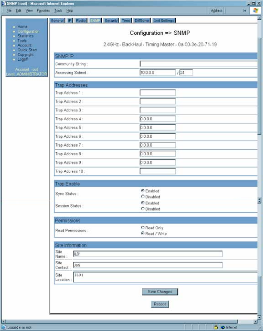
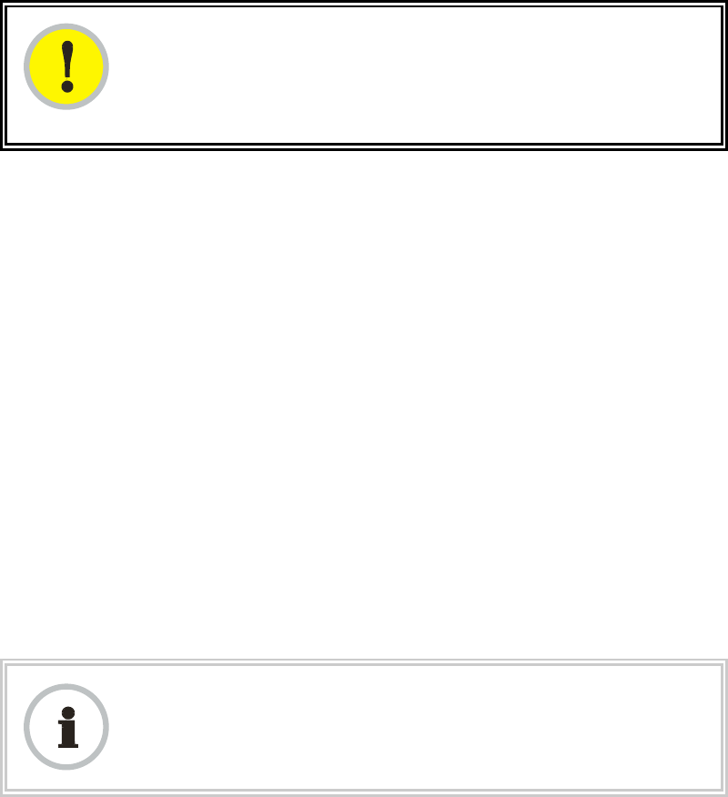
18.4.4 SNMP Tab of the BHM
An example of the SNMP tab in a BHM is displayed in Figure 103.
Figure 103: SNMP tab of BHM, example
In the SNMP tab of the BHM, you may set the following parameters.

Release 8 Installation and Configuration Guide
Issue 2, November 2007 Draft 5 for Regulatory Review 304
Community String
Specify a control string that allows Prizm or a Network Management Station (NMS) to
access the module through SNMP. No spaces are allowed in this string. The default
string is Canopy.
The Community String value is clear text and is readable by a packet monitor.
Additional security derives from the configuration of the Accessing Subnet, Trap
Address, and Permission parameters.
Accessing Subnet
Specify the addresses that are allowed to send SNMP requests to this BHM. Prizm or
the NMS has an address that is among these addresses (this subnet). You must enter
both
◦ The network IP address in the form xxx.xxx.xxx.xxx
◦ The CIDR (Classless Interdomain Routing) prefix length in the form /xx
For example
◦ the /16 in 198.32.0.0/16 specifies a subnet mask of 255.255.0.0 (the first 16 bits
in the address range are identical among all members of the subnet).
◦ 192.168.102.0 specifies that any device whose IP address is in the range
192.168.102.0 to 192.168.102.254 can send SNMP requests to the BHM,
presuming that the device supplies the correct Community String value.
NOTE:
For more information on CIDR, execute an Internet search on “Classless
Interdomain Routing.”
The default treatment is to allow all networks access.
Trap Address 1 to 10
Specify ten or fewer IP addresses (xxx.xxx.xxx.xxx) to which trap information should be
sent. Trap information informs Prizm or an NMS that something has occurred. For
example, trap information is sent
◦ after a reboot of the module.
◦ when Prizm or an NMS attempts to access agent information but either
− supplied an inappropriate community string or SNMP version number.
− is associated with a subnet to which access is disallowed.
Trap Enable
Select either Sync Status or Session Status to enable SNMP traps. If you select
neither, then traps are disabled.
Read Permissions
Select Read Only if you wish to disallow any parameter changes by Prizm or an NMS.
Release 8 Installation and Configuration Guide
Issue 2, November 2007 Draft 5 for Regulatory Review 305
Site Name
Specify a string to associate with the physical module. This parameter is written into the
sysName SNMP MIB-II object and can be polled by an NMS. The buffer size for this field
is 128 characters.
Site Contact
Enter contact information for the module administrator. This parameter is written into the
sysContact SNMP MIB-II object and can be polled by an NMS. The buffer size for this
field is 128 characters.
Site Location
Enter information about the physical location of the module. This parameter is written into
the sysLocation SNMP MIB-II object and can be polled by an NMS. The buffer size for
this field is 128 characters.
The SNMP tab also provides the following buttons.
Save Changes
When you click this button, any changes that you made on the Configuration page are
recorded in flash memory. However, these changes do not apply until the next reboot of
the module.
Reboot
When you click this button
1. the module reboots.
2. any changes that you saved by a click of the Save Changes button are
implemented.
Release 8 Installation and Configuration Guide
Issue 2, November 2007 Draft 5 for Regulatory Review 306
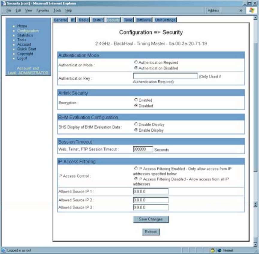
18.4.5 Security Tab of the BHM
An example of the Security tab in a BHM is displayed in Figure 104.
Figure 104: Security tab of BHM, example
In the Security tab of the BHM, you may set the following parameters.
Authentication Mode
Specify whether the BHM should require the BHS to authenticate.
Authentication Key
Only if you set the BHM in the previous parameter to require authentication, specify the
key that the BHS should use when authenticating.

Release 8 Installation and Configuration Guide
Issue 2, November 2007 Draft 5 for Regulatory Review 307
Encryption
Specify the type of air link security to apply to this BHM:
◦ Encryption Disabled provides no encryption on the air link. This is the default
mode.
◦ Encryption Enabled provides encryption, using a factory-programmed secret
key that is unique for each module.
NOTE:
In any BH link where encryption is enabled, the BHS briefly drops registration
and re-registers in the BHM every 24 hours to change the encryption key.
BHS Display of BHM Evaluation Data
You can use this field to suppress the display of data (Disable Display) about this BHM
on the BHM Evaluation tab of the Tools page in the BHS.
Web, Telnet, FTP Session Timeout
Enter the expiry in seconds for remote management sessions via HTTP, telnet, or ftp
access to the BHM.
IP Access Control
You can permit access to the BHM from any IP address (IP Access Filtering Disabled)
or limit it to access from only one, two, or three IP addresses that you specify (IP Access
Filtering Enabled). If you select IP Access Filtering Enabled, then you must populate
at least one of the three Allowed Source IP parameters or have no access permitted
from any IP address, including access and management by Prizm.
Allowed Source IP 1 to 3
If you selected IP Access Filtering Enabled for the IP Access Control parameter, then
you must populate at least one of the three Allowed Source IP parameters or have no
access permitted to the BHM from any IP address. You may populate as many as all
three.
If you selected IP Access Filtering Disabled for the IP Access Control parameter, then
no entries in this parameter are read, and access from all IP addresses is permitted.
The Security tab also provides the following buttons.
Save Changes
When you click this button, any changes that you made on the Configuration page are
recorded in flash memory. However, these changes do not apply until the next reboot of
the module.
Release 8 Installation and Configuration Guide
Issue 2, November 2007 Draft 5 for Regulatory Review 308
Reboot
When you click this button
1. the module reboots.
2. any changes that you saved by a click of the Save Changes button are
implemented.
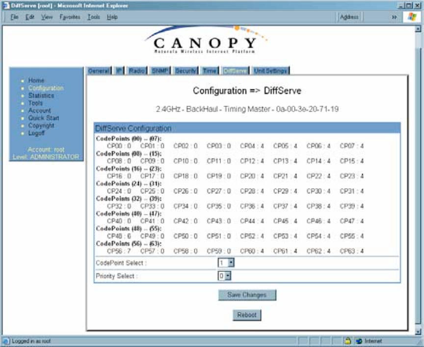
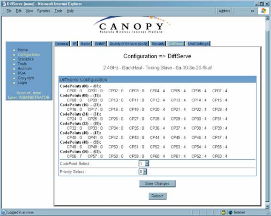
18.4.6 DiffServe Tab of the BHM
An example of the DiffServe tab in a BHM is displayed in Figure 105.
Figure 105: DiffServe tab of BHM, example

Release 8 Installation and Configuration Guide
Issue 2, November 2007 Draft 5 for Regulatory Review 309
In the DiffServe tab of the BHM, you may set the following parameters.
CodePoint 1
through
CodePoint 47
CodePoint 49
through
CodePoint 55
CodePoint 57
through
CodePoint 63
The default priority value for each settable CodePoint is shown in
Figure 113. Priorities of 0 through 3 map to the low-priority channel;
4 through 7 to the high-priority channel. The mappings are the same
as 802.1p VLAN priorities.
Consistent with RFC 2474
◦ CodePoint 0 is predefined to a fixed priority value of 0
(low-priority channel).
◦ CodePoint 48 is predefined to a fixed priority value of 6
(high-priority channel).
◦ CodePoint 56 is predefined to a fixed priority value of 7
(high-priority channel).
You cannot change any of these three fixed priority values. Among
the settable parameters, the priority values (and therefore the
handling of packets in the high- or low-priority channel) are set in
the AP for all downlinks within the sector and in the SM for each
uplink. See DSCP Field on Page 87.
The DiffServe tab also provides the following buttons.
Save Changes
When you click this button, any changes that you made on the Configuration page are
recorded in flash memory. However, these changes do not apply until the next reboot of
the module.
Reboot
When you click this button
1. the module reboots.
2. any changes that you saved by a click of the Save Changes button are
implemented.
Release 8 Installation and Configuration Guide
Issue 2, November 2007 Draft 5 for Regulatory Review 310
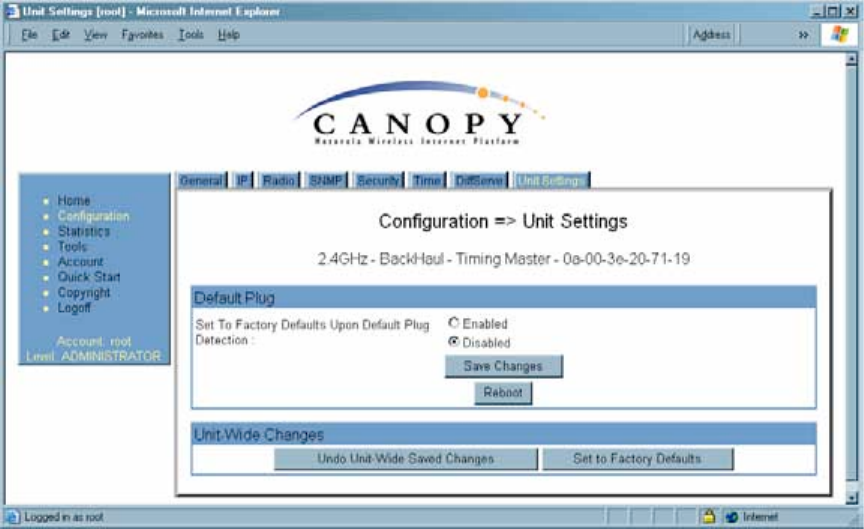
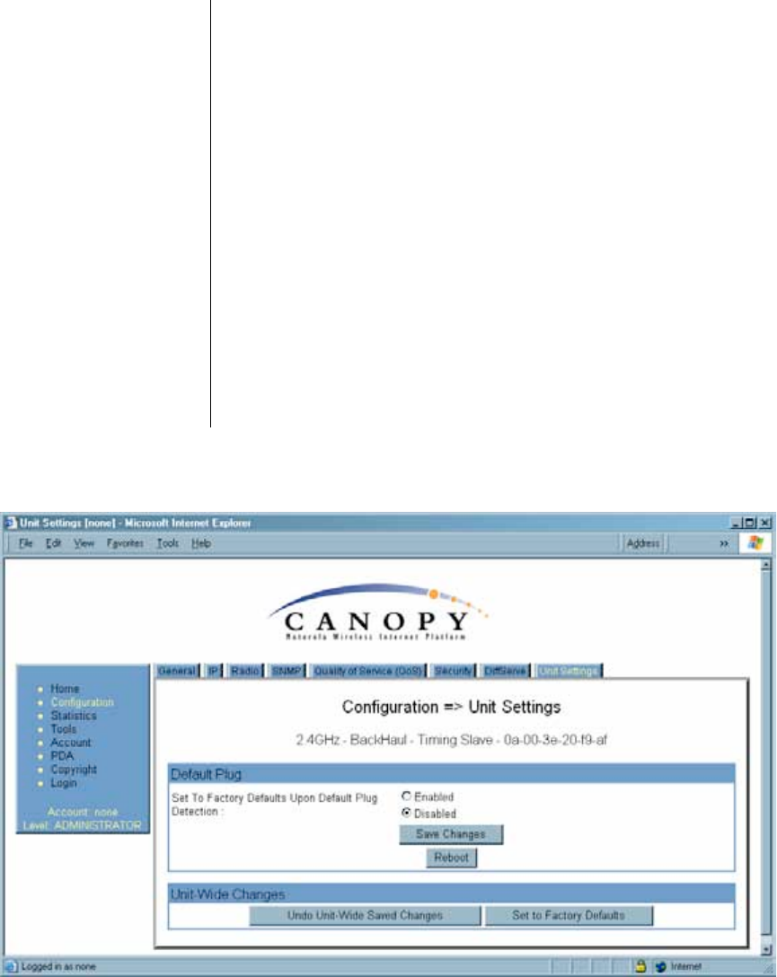
18.4.7 Unit Settings Tab of the BHM
An example of the Unit Settings tab of the BHM is displayed in Figure 106.
Figure 106: Unit Settings tab of BHM, example
The Unit Settings tab of the BHM contains an option for how the BHM should react when
it detects a connected override plug. You may set this option as follows.
Set to Factory Defaults Upon Default Plug Detection
If Enabled is checked, then an override/default plug functions as a default plug. When
the module is rebooted with the plug inserted, it can be accessed at the IP address
169.254.1.1 and no password, and all parameter values are reset to defaults.
A subscriber, technician, or other person who gains physical access to the module and
uses an override/default plug cannot see or learn the settings that were previously
configured in it. When the module is later rebooted with no plug inserted, the module
uses the new values for any parameters that were changed and the default values for
any that were not.
If Disabled is checked, then an override/default plug functions as an override plug. When
the module is rebooted with the plug inserted, it can be accessed at the IP address
169.254.1.1 and no password, and all previously configured parameter values remain
and are displayed. A subscriber, technician, or other person who gains physical access
to the module and uses an override/default plug can see and learn the settings. When the
module is later rebooted with no plug inserted, the module uses the new values for any
parameters that were changed and the previous values for any that were not.
See Overriding Forgotten IP Addresses or Passwords on AP, SM, or BH on Page 373.
The Unit Settings tab also contains the following buttons.
Release 8 Installation and Configuration Guide
Issue 2, November 2007 Draft 5 for Regulatory Review 311
Save Changes
When you click this button, any changes that you made on the Configuration page are
recorded in flash memory. However, these changes do not apply until the next reboot of
the module.
Reboot
When you click this button
1. the module reboots.
2. any changes that you saved by a click of the Save Changes button are
implemented.
Release 8 Installation and Configuration Guide
Issue 2, November 2007 Draft 5 for Regulatory Review 312
18.5 CONFIGURING A BH TIMING SLAVE FOR THE DESTINATION
If an ADMINISTRATOR-level password has been set in the BHS, you must log into the
module before you can configure its parameters. See Managing Module Access by
Passwords on Page 371.
18.5.1 General Tab of the BHS
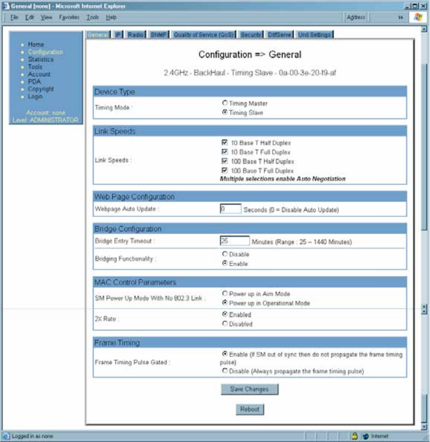
An example of the General tab in a BHS is displayed in Figure 107.
Figure 107: General tab of BHS, example
In the General tab of the BHS, you may set the following parameters.
Release 8 Installation and Configuration Guide
Issue 2, November 2007 Draft 5 for Regulatory Review 313
Timing Mode
Select Timing Slave. This BH will receive sync from another source. Whenever you
toggle this parameter to Timing Slave from Timing Master, you should also do the
following:
1. Make no other changes in this or any other interface page.
2. Save this change of timing mode.
3. Reboot the BH.
RESULT: The set of interface web pages that is unique to a BHS is made available.
NOTE:
In a BHS that cannot be converted to a BHM, this parameter is not present (for
example, in a BHS with Hardware Scheduling and Series P8 hardware.)
Link Speeds
Specify the type of link speed for the Ethernet connection. The default for this parameter
is that all speeds are selected. The recommended setting is a single speed selection for
all APs, BHs, and SMs in the operator network.
Webpage Auto Update
Enter the frequency (in seconds) for the web browser to automatically refresh the web-
based interface. The default setting is 0. The 0 setting causes the web-based interface to
never be automatically refreshed.
Bridge Entry Timeout
Specify the appropriate bridge timeout for correct network operation with the existing
network infrastructure. Timeout occurs when the BHM encounters no activity with the
BHS (whose MAC address is the bridge entry) within the interval that this parameter
specifies. The Bridge Entry Timeout should be a longer period than the ARP (Address
Resolution Protocol) cache timeout of the router that feeds the network.
This parameter governs the timeout interval, even if a router in the system has a longer
timeout interval. The default value of this field is 25 minutes.
CAUTION!
An inappropriately low Bridge Entry Timeout setting may lead to temporary loss
of communication with some end users.
Bridging Functionality
Select whether you want bridge table filtering active (Enable) or not (Disable) on this
BHS. Selecting Disable allows you to use redundant BHs without causing network
addressing problems. Through a spanning tree protocol, this reduces the convergence
time from 25 minutes to mere seconds. However, you should disable bridge table filtering
as only a deliberate part of your overall network design. Otherwise, disabling it allows
unwanted traffic across the wireless interface.
Release 8 Installation and Configuration Guide
Issue 2, November 2007 Draft 5 for Regulatory Review 314
SM Power Up Mode With No 802.3 Link
Specify the default mode in which this BHS will power up when it senses no Ethernet link.
Select either
◦ Power Up in Aim Mode—the BHS boots in an aiming mode. When the BHS
senses an Ethernet link, this parameter is automatically reset to Power Up in
Operational Mode. When the BHS senses no Ethernet link within 15 minutes
after power up, the BHS carrier shuts off.
◦ Power Up in Operational Mode—the BHS boots in Operational mode and
attempts registration. Unlike in previous releases, this is the default selection in
Release 8.
2X Rate
See 2X Operation on Page 89.
Frame Timing Pulse Gated
If this BHS extends the sync pulse to a BHM or an AP behind it, select either
◦ Enable—If this BHS loses sync, then do not propagate a sync pulse to the BHM
or AP. This setting prevents interference in the event that the BHS loses sync.
◦ Disable—If this BHS loses sync, then propagate the sync pulse anyway to the
BHM or AP.
See Wiring to Extend Network Sync on Page 367.
The General tab also provides the following buttons.
Save Changes
When you click this button, any changes that you made on the Configuration page are
recorded in flash memory. However, these changes do not apply until the next reboot of
the module.
Reboot
When you click this button
1. the module reboots.
2. any changes that you saved by a click of the Save Changes button are
implemented.
Release 8 Installation and Configuration Guide
Issue 2, November 2007 Draft 5 for Regulatory Review 315
18.5.2 IP Tab of the BHS
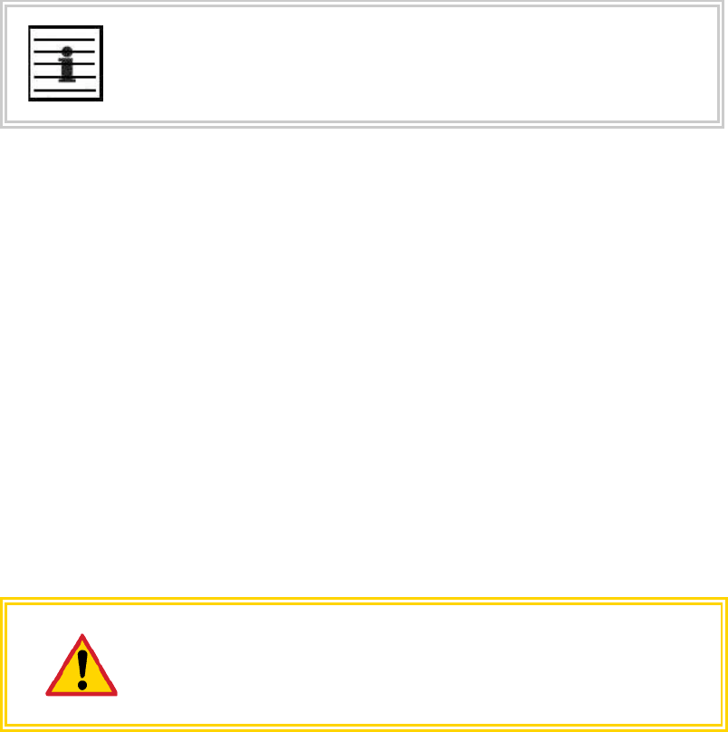
An example of the IP tab in a BHS is displayed in Figure 108.
Figure 108: IP tab of BHS, example
In the IP tab of the BHS, you may set the following parameters.
LAN1 Network Interface Configuration, IP Address
Enter the non-routable IP address to associate with the Ethernet connection on this BHS.
(The default IP address from the factory is 169.254.1.1.) If you set and then forget this
parameter, then you must both
1. physically access the module.
2. use an override plug to electronically access the module configuration
parameters at 169.254.1.1. See Overriding Forgotten IP Addresses or
Passwords on AP, SM, or BH on Page 375.
RECOMMENDATION:
Note or print the IP settings from this page. Ensure that you can readily
associate these IP settings both with the module and with the other data that you
store about the module.
LAN1 Network Interface Configuration, Subnet Mask
Enter an appropriate subnet mask for the BHS to communicate on the network. The
default subnet mask is 255.255.0.0. See Allocating Subnets on Page 162.
Release 8 Installation and Configuration Guide
Issue 2, November 2007 Draft 5 for Regulatory Review 316
LAN1 Network Interface Configuration, Gateway IP Address
Enter the appropriate gateway for the BHS to communicate with the network. The default
gateway is 169.254.0.0.
LAN1 Network Interface Configuration, DHCP State
If you select Enabled, the DHCP server automatically assigns the IP configuration
(IP address, subnet mask, and gateway IP address) and the values of those individual
parameters (above) are not used. The setting of this DHCP state parameter is also
viewable, but not settable, in the Network Interface tab of the Home page.
The IP tab also provides the following buttons.
Save Changes
When you click this button, any changes that you made on the IP Configuration page are
recorded in flash memory. However, these changes do not apply until the next reboot of
the module.
Reboot
When you click this button
1. the module reboots.
2. any changes that you saved by a click of the Save Changes button are
implemented.
18.5.3 Radio Tab of the BHS
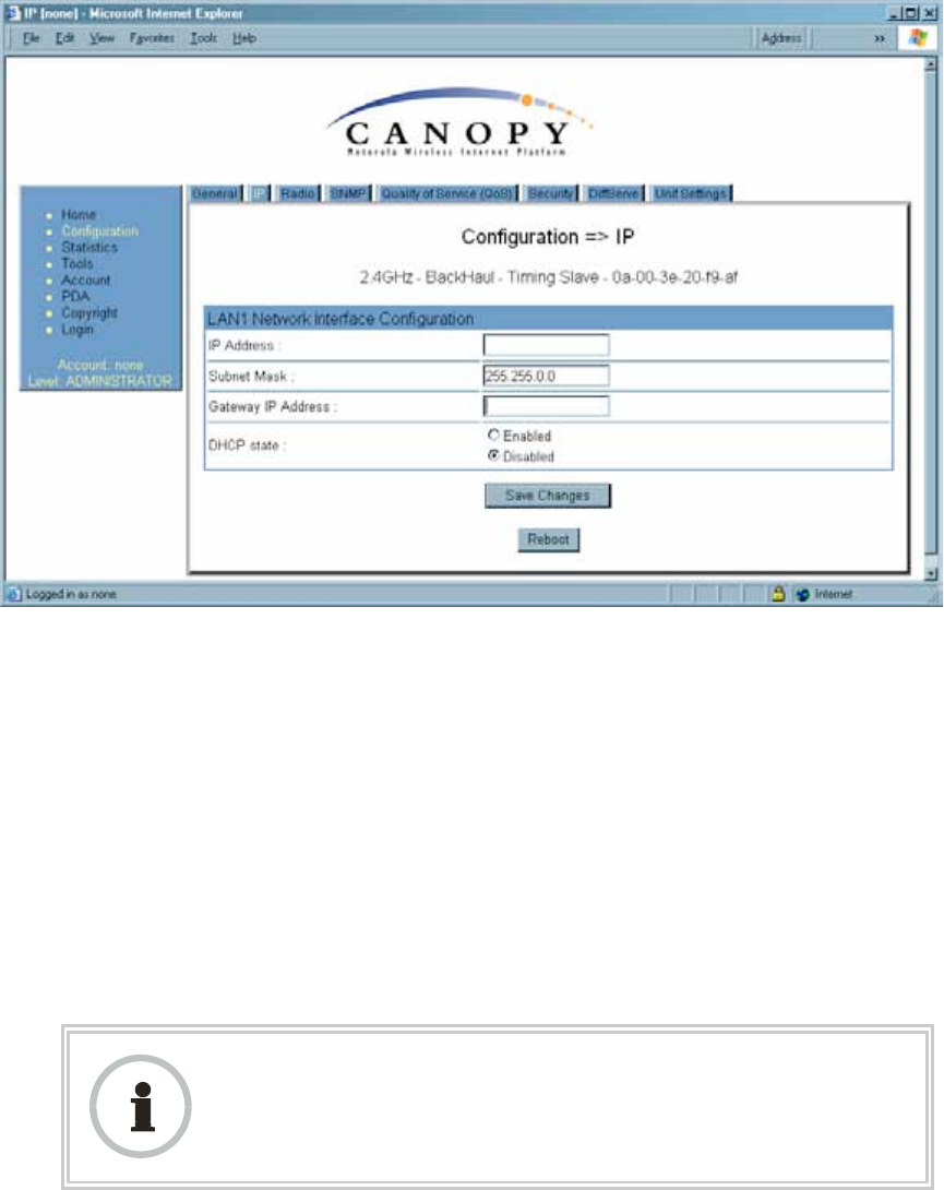
An example of the Radio tab in a BHS is displayed in Figure 109.
Release 8 Installation and Configuration Guide
Issue 2, November 2007 Draft 5 for Regulatory Review 317
Figure 109: Radio tab of BHS, example
In the Radio tab of the BHS, you may set the following parameters.
Custom Radio Frequency Scan Selection List
Specify the frequency that the BHS should scan to find the BHM. The frequency band of
the BHs affects what channels you select.
IMPORTANT!
In the 2.4-GHz frequency band, the BHS can register to a BHM that transmits on
a frequency 2.5 MHz higher than the frequency that the BHS receiver locks
when the scan terminates as successful. This establishes a poor-quality link. To
prevent this, select frequencies that are at least 5 MHz apart.
In a 2.4-GHz BHS, this parameter displays all available channels, but has only three
recommended channels selected by default. See 2.4-GHz AP Cluster Recommended
Channels on Page 137.
In a 5.2- or 5.4-GHz BHS, this parameter displays only ISM frequencies. In a 5.7-GHz
BHS, this parameter displays both ISM and U-NII frequencies. If you select all
frequencies that are listed (default selections), then the module scans for a signal on any
channel. If you select only one, then the module limits the scan to that channel. Since the
frequencies that this parameter offers for each of these two bands are 5 MHz apart, a
scan of all channels does not risk establishment of a poor-quality link as in the 2.4-GHz
band. Nevertheless, this can risk establishment of a link to the wrong BHM.
A list of channels in the band is provided in Considering Frequency Band Alternatives on
Page 136.
(The selection labeled Factory requires a special software key file for implementation.)
Color Code
Specify a value from 0 to 254. For registration to occur, the color code of the BHM and
the BHS must match. On all Canopy modules, the default setting for the color code value
is 0. This value matches only the color code of 0 (not all 255 color codes).
RECOMMENDATION:
Note the color code that you enter. Ensure that you can readily associate this
color code both with the module and with the other data that you store about the
module.
Transmitter Output Power
Nations and regions may regulate transmitter output power. For example
◦ Both 900-MHz and 5.7-GHz modules are available as connectorized radios,
which require the operator to adjust power to ensure regulatory compliance. In
addition to setting the power in the 5.7-GHz connectorized module, the operator
Release 8 Installation and Configuration Guide
Issue 2, November 2007 Draft 5 for Regulatory Review 318
must set the antenna gain/cable loss such that the module can accurately report
received power at the antenna.
◦ Legal maximum allowable transmitter output power and EIRP (Equivalent
Isotropic Radiated Power) in the 2.4-GHz frequency band varies by country and
region. The output power of Series P9 2.4-GHz modules can be adjusted to meet
these national or regional regulatory requirements.
◦ Countries and regions that permit the use of the 5.4-GHz frequency band (CEPT
member states, for example), generally require equipment using the band to
have adjustable power.
The professional installer of Canopy equipment has the responsibility to
◦ maintain awareness of applicable regulations.
◦ calculate the permissible transmitter output power for the module.
◦ confirm that the initial power setting is compliant with national or regional
regulations.
◦ confirm that the power setting is compliant following any reset of the module to
factory defaults.
For information on how to calculate the permissible transmitter output power to enter in
this parameter, see Adjusting Transmitter Output Power on Page 326.
The Radio tab also provides the following buttons.
Save Changes
When you click this button, any changes that you made on this tab are recorded in flash
memory. However, these changes do not apply until the next reboot of the module.
Reboot
When you click this button
1. the module reboots.
2. any changes that you saved by a click of the Save Changes button are
implemented.
Release 8 Installation and Configuration Guide
Issue 2, November 2007 Draft 5 for Regulatory Review 319
18.5.4 SNMP Tab of the BHS
An example of the SNMP tab in a BHS is displayed in Figure 110.
Figure 110: SNMP tab of BHS, example
In the SNMP tab of the BHS, you may set the following parameters.
Community String
Specify a control string that allows Prizm or an NMS (Network Management Station) to
access MIB information about this BHS. No spaces are allowed in this string. The default
string is Canopy.
Release 8 Installation and Configuration Guide
Issue 2, November 2007 Draft 5 for Regulatory Review 320
The Community String value is clear text and is readable by a packet monitor.
Additional security derives from the configuration of the Accessing Subnet, Trap
Address, and Permission parameters.
Accessing Subnet
Specify the addresses that are allowed to send SNMP requests to this BHS. Prizm or
the NMS has an address that is among these addresses (this subnet). You must enter
both
◦ The network IP address in the form xxx.xxx.xxx.xxx
◦ The CIDR (Classless Interdomain Routing) prefix length in the form /xx
For example
◦ the /16 in 198.32.0.0/16 specifies a subnet mask of 255.255.0.0 (the first 16 bits
in the address range are identical among all members of the subnet).
◦ 192.168.102.0 specifies that any device whose IP address is in the range
192.168.102.0 to 192.168.102.254 can send SNMP requests to the BHS,
presuming that the device supplies the correct Community String value.
The default treatment is to allow all networks access (set to 0). For more information on
CIDR, execute an Internet search on “Classless Interdomain Routing.”
Trap Address 1 to 10
Specify ten or fewer IP addresses (xxx.xxx.xxx.xxx) to which trap information should be
sent. Trap information informs Prizm or an NMS that something has occurred. For
example, trap information is sent
◦ after a reboot of the module.
◦ when Prizm or an NMS attempts to access agent information but either
− supplied an inappropriate community string or SNMP version number.
− is associated with a subnet to which access is disallowed.
Read Permissions
Select Read Only if you wish to disallow Prizm or NMS SNMP access to configurable
parameters and read-only fields of the SM.
Site Name
Specify a string to associate with the physical module. This parameter is written into the
sysName SNMP MIB-II object and can be polled by Prizm or an NMS. The buffer size for
this field is 128 characters.
Site Contact
Enter contact information for the module administrator. This parameter is written into the
sysContact SNMP MIB-II object and can be polled by Prizm or an NMS. The buffer size
for this field is 128 characters.
Site Location
Enter information about the physical location of the module. This parameter is written into
the sysLocation SNMP MIB-II object and can be polled by Prizm or an NMS. The buffer
size for this field is 128 characters.
Release 8 Installation and Configuration Guide
Issue 2, November 2007 Draft 5 for Regulatory Review 321
The SNMP tab also provides the following buttons.
Save Changes
When you click this button, any changes that you made on the Configuration page are
recorded in flash memory. However, these changes do not apply until the next reboot of
the module.
Reboot
When you click this button
1. the module reboots.
2. any changes that you saved by a click of the Save Changes button are
implemented.
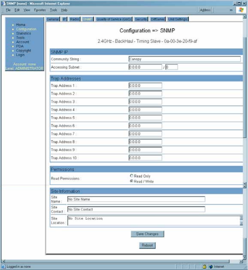
18.5.5 Quality of Service (QoS) Tab of the BHS
An example of the Quality of Service tab of the BHS is displayed in Figure 111.
Figure 111: Quality of Service (QoS) tab of BHS, example
In the Quality of Service (QoS) tab of the BHS, you may set the following parameters.
Low Priority Uplink CIR
See
◦ Committed Information Rate on Page 86
◦ Setting the Configuration Source on Page 292.
Low Priority Downlink CIR
See
◦ Committed Information Rate on Page 86
Release 8 Installation and Configuration Guide
Issue 2, November 2007 Draft 5 for Regulatory Review 322
◦ Setting the Configuration Source on Page 292.
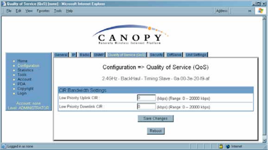
18.5.6 Security Tab of the BHS
An example of the Security tab in a BHS is displayed in Figure 112.
Figure 112: Security tab of BHS, example
In the Security tab of the BHS, you may set the following parameters.
Authentication Key
Only if the BHM to which this BHS will register requires authentication, specify the key
that the BHS should use when authenticating. For alpha characters in this hex key, use
only upper case.
NOTE:
Canopy recommends that you enter 32 characters to achieve the maximal
security from this feature.
Release 8 Installation and Configuration Guide
Issue 2, November 2007 Draft 5 for Regulatory Review 323
Select Key
The Use Default Key selection specifies that the link should continue to use the
automatically generated authentication key. See Authentication Manager Capability on
Page 383.
The Use Key above selection specifies the 32-digit hexadecimal key that is permanently
stored on both the BHS and the BHM.
Web, Telnet, FTP Session Timeout
Enter the expiry in seconds for remote management sessions via HTTP, telnet, or ftp
access to the BHS.
IP Access Control
You can permit access to the BHS from any IP address (IP Access Filtering Disabled)
or limit it to access from only one, two, or three IP addresses that you specify (IP Access
Filtering Enabled). If you select IP Access Filtering Enabled, then you must populate
at least one of the three Allowed Source IP parameters or have no access permitted
from any IP address, including access and management by Prizm.
Allowed Source IP 1 to 3
If you selected IP Access Filtering Enabled for the IP Access Control parameter, then
you must populate at least one of the three Allowed Source IP parameters or have no
access permitted to the BHS from any IP address. You may populate as many as all
three.
If you selected IP Access Filtering Disabled for the IP Access Control parameter, then
no entries in this parameter are read, and access from all IP addresses is permitted.
The Security tab of the BHS also provides the following buttons.
Save Changes
When you click this button, any changes that you made on this tab are recorded in flash
memory. However, these changes do not apply until the next reboot of the module.
Reboot
When you click this button
1. the module reboots.
2. any changes that you saved by a click of the Save Changes button are
implemented.
Release 8 Installation and Configuration Guide
Issue 2, November 2007 Draft 5 for Regulatory Review 324
18.5.7 DiffServe Tab of the BHS
An example of the DiffServe tab in a BHS is displayed in Figure 113.
Figure 113: DiffServe tab of BHS, example
Release 8 Installation and Configuration Guide
Issue 2, November 2007 Draft 5 for Regulatory Review 325
You may set the following Differentiated Services Configuration page parameters.
CodePoint 1
through
CodePoint 47
CodePoint 49
through
CodePoint 55
CodePoint 57
through
CodePoint 63
The default priority value for each settable CodePoint is shown in
Figure 113. Priorities of 0 through 3 map to the low-priority channel;
4 through 7 to the high-priority channel. The mappings are the same
as 802.1p VLAN priorities.
Consistent with RFC 2474
◦ CodePoint 0 is predefined to a fixed priority value of 0
(low-priority channel).
◦ CodePoint 48 is predefined to a fixed priority value of 6
(high-priority channel).
◦ CodePoint 56 is predefined to a fixed priority value of 7
(high-priority channel).
You cannot change any of these three fixed priority values. Among
the settable parameters, the priority values (and therefore the
handling of packets in the high- or low-priority channel) are set in
the BHM for the downlink and in the BHS for the uplink. See DSCP
Field on Page 87.
18.5.8 Unit Settings Tab of the BHS
An example of the Unit Settings tab in a BHS is displayed in Figure 114.
Figure 114: Unit Settings tab of BHS, example
The Unit Settings tab of the BHS contains an option for how the BHS should react when it
detects a connected override plug. You may set this option as follows.
Release 8 Installation and Configuration Guide
Issue 2, November 2007 Draft 5 for Regulatory Review 326
Set to Factory Defaults Upon Default Plug Detection
If Enabled is checked, then an override/default plug functions as a default plug. When
the module is rebooted with the plug inserted, it can be accessed at the IP address
169.254.1.1 and no password, and all parameter values are reset to defaults.
A subscriber, technician, or other person who gains physical access to the module and
uses an override/default plug cannot see or learn the settings that were previously
configured in it. When the module is later rebooted with no plug inserted, the module
uses the new values for any parameters that were changed and the default values for
any that were not.
If Disabled is checked, then an override/default plug functions as an override plug. When
the module is rebooted with the plug inserted, it can be accessed at the IP address
169.254.1.1 and no password, and all previously configured parameter values remain
and are displayed. A subscriber, technician, or other person who gains physical access
to the module and uses an override/default plug can see and learn the settings. When the
module is later rebooted with no plug inserted, the module uses the new values for any
parameters that were changed and the previous values for any that were not.
See Overriding Forgotten IP Addresses or Passwords on AP, SM, or BH on Page 373.
The Unit Settings tab also contains the following buttons.
Save Changes
When you click this button, any changes that you made on all tabs are recorded in flash
memory. However, these changes do not apply until the next reboot of the module.
Reboot
When you click this button
1. the module reboots.
2. any changes that you saved by a click of the Save Changes button are
implemented.
Undo Unit-Wide Saved Changes
When you click this button, any changes that you made in any tab but did not commit by
a reboot of the module are undone.
Set to Factory Defaults
When you click this button, all configurable parameters on all tabs are reset to the factory
settings.
18.6 ADJUSTING TRANSMITTER OUTPUT POWER
Authorities may require transmitter output power to be adjustable and/or lower than the
highest that a module produces. Canopy adjustable power modules include a Radio tab
parameter to reduce power on an infinite scale to achieve compliance. If you set this
parameter to lower than the supported range extends, the value is automatically reset to
the lowest supported value.
The professional installer of Canopy equipment has the responsibility to
◦ maintain awareness of applicable regulations.
◦ calculate the permissible transmitter output power for the module.
◦ confirm that the initial power setting is compliant.
Release 8 Installation and Configuration Guide
Issue 2, November 2007 Draft 5 for Regulatory Review 327
◦ confirm that the power setting is compliant following any reset of the module to
factory defaults.
The total gain per antenna in 900-MHz and 5.7-GHz Canopy radios is stated in Table 48.
Table 48: Total gain per antenna
Antenna
Antenna Gain
Cable Loss1
Net Gain
900-MHz Integrated
12.5 dBi
0.2 dB
12 dBi
900-MHz Connectorized2
10 to 10.5 dBi
0.3 dB
10 dBi
5.7-GHz Connectorized
settable
0.3 dB + from
any additional
cable
See Note 3
NOTES:
1. Received signal measurements take this loss into account, but the
transmitter output power setting cannot. Set the transmitter output
power higher by this amount.
2. With Mars, MTI, or Maxrad antenna.
3. Antenna gain minus cable loss.
Integrated patch antenna and reflector gains are provided in Table 49.
Table 49: Patch antenna and reflector gain
Gain
Frequency
Band Range
Patch
Antenna
Reflector
2.4 GHz
8 dBi
11dBi
5.2, 5.4, or
5.7 GHz
7 dBi
18dBi
The calculation of transmitter output power is as follows:
Transmitter
Output
Power
=
EIRP
Patch
Antenna
Gain
Reflector
Gain
- -
solve, then set
in parameter
from applicable
regulations
from the preceding
table
from the preceding
table

Release 8 Installation and Configuration Guide
Issue 2, November 2007 Draft 5 for Regulatory Review 328
Transmitter output power is settable as dBm on the Radio tab of the module. Example
cases of transmitter output power settings are shown in Table 50.
Table 50: Transmitter output power settings, example cases
Transmitter Output
Power Setting
Frequency Band Range
and Antenna Scheme
Region
Maximum EIRP
in Region
AP, SM, or BH
with
No Reflector
SM or BH with
Reflector
900 MHz Integrated
U.S.A.
Canada
36 dBm (4 W)
24 dBm
U.S.A.
Canada
36 dBm (4 W)
26 dBm1
900 MHz Connectorized
Australia
30 dBm (1 W)
Depends on
antenna
U.S.A.
Canada
Depends on
antenna gain
25 dBm
25 dBm
2.4 GHz Integrated
CEPT
states
20 dBm (100 mW)
12 dBm
1 dBm
5.2 GHz Integrated
U.S.A.
Canada
30 dBm (1 W)
23 dBm
5.4 GHz Integrated
CEPT
states
30 dBm (1 W)
23 dBm
5 dBm
5.7 GHz Connectorized
UK
33 dBm (2 W)
Depends on
antenna
Depends on
antenna
NOTES:
1. With Mars, MTI, or Maxrad antenna. This is the default setting, and 28 dBm is the highest settable
value. The lower default correlates to 36 dBm EIRP where 10-dBi antennas are used. The default
setting for this parameter is applied whenever Set to Factory Defaults is selected.

Release 8 Installation and Configuration Guide
Issue 2, November 2007 Draft 5 for Regulatory Review 329
19 INSTALLING COMPONENTS
RECOMMENDATION:
Use shielded cable for all Canopy infrastructure connections associated with
BHs, APs, and CMMs. The environment that these modules operate in often has
significant unknown or varying RF energy. Operator experience consistently
indicates that the additional cost of shielded cables is more than compensated
by predictable operation and reduced costs for troubleshooting and support.
19.1 PDA ACCESS TO CANOPY MODULES
For RF spectrum analysis or module aiming on a roof or tower, a personal digital
assistant (PDA) is easier to carry than, and as convenient to use as, a notebook
computer. The PDA is convenient to use because no scrolling is required to view
◦ spectrum analysis results.
◦ RSSI and jitter.
◦ master module evaluation data.
◦ information that identifies the module, software, and firmware.
To access this data in a format the fits a 320 x 240 pixel PDA screen, the PDA must have
all of the following:
◦ a Compact Flash card slot.
◦ any of several Compact Flash wired Ethernet cards.
◦ a wired Ethernet connection to the module.
◦ a browser directed to http://ModuleIPAddress/pda.html.
The initial PDA tab reports link status, as shown in Figure 115.
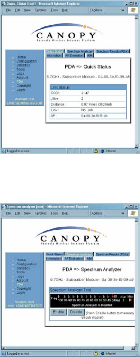
Release 8 Installation and Configuration Guide
Issue 2, November 2007 Draft 5 for Regulatory Review 330
Figure 115: PDA Quick Status tab, example
An example of the Spectrum Analyzer tab for PDAs is displayed in Figure 116. For
additional information about the Spectrum Analyzer feature, see Monitoring the RF
Environment on Page 363.
Figure 116: PDA Spectrum Analyzer tab of SM, example
Examples of the Spectrum Results and Information tabs for PDAs are shown in
Figure 117 and Figure 118.
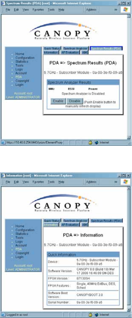
Release 8 Installation and Configuration Guide
Issue 2, November 2007 Draft 5 for Regulatory Review 331
Figure 117: PDA Spectrum Results tab of SM, example
Figure 118: PDA Information tab of SM, example
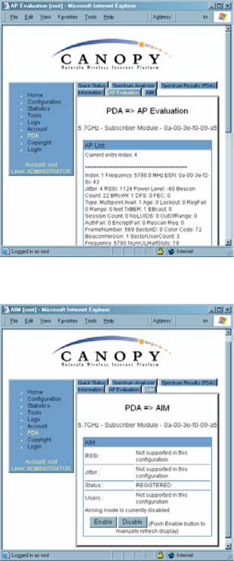
Examples of the AP Evaluation and Aim tabs for PDAs are shown in Figure 119 and
Figure 120.
Release 8 Installation and Configuration Guide
Issue 2, November 2007 Draft 5 for Regulatory Review 332
Figure 119: PDA AP Evaluation tab of SM, example
Figure 120: PDA Aim tab of SM, example
19.2 INSTALLING AN AP
To install the Canopy AP, perform the following steps.
Procedure 19: Installing the AP

Release 8 Installation and Configuration Guide
Issue 2, November 2007 Draft 5 for Regulatory Review 333
1. Begin with the AP in the powered-down state.
2. Choose the best mounting location for your particular application. Modules need
not be mounted next to each other. They can be distributed throughout a given
site. However, the 60° offset must be maintained. Mounting can be done with
stainless steel hose clamps or another equivalent fastener.
3. Align the AP as follows:
a. Move the module to where the link will be unobstructed by the radio horizon
and no objects penetrate the Fresnel zone. (The Canopy System Calculator
page AntennaElevationCalcPage.xls automatically calculates the minimum
antenna elevation that is required to extend the radio horizon to the other end
of the link. The Canopy System Calculator page FresnelZoneCalcPage.xls
automatically calculates the Fresnel zone clearance that is required between
the visual line of sight and the top of a high-elevation object.)
b. Use a local map, compass, and/or GPS device as needed to determine the
direction that one or more APs require to each cover the intended 60° sector.
c. Apply the appropriate degree of downward tilt. (The Canopy System
Calculator page DowntiltCalcPage.xls automatically calculates the angle of
antenna downward tilt that is required.)
d. Ensure that the nearest and furthest SMs that must register to this AP are
within the beam coverage area. (The Canopy System Calculator page
BeamwidthRadiiCalcPage.xls automatically calculates the radii of the beam
coverage area.)
4. Using stainless steel hose clamps or equivalent fasteners, lock the AP in the
proper direction and downward tilt.
5. Remove the base cover of the AP. (See Figure 46 on Page 178.)
6. Attach the cables to the AP.
(See Procedure 5 on Page 184.)
NOTE: When power is applied to a Canopy module or the unit is reset on the web-based
interface, the module requires approximately 25 seconds to boot. During this interval,
self-tests and other diagnostics are being performed. See Table 40 on Page 179.
=========================== end of procedure ===========================
19.3 INSTALLING A CONNECTORIZED FLAT PANEL ANTENNA
To install a connectorized flat panel antenna to a mast or structure, follow instructions
that the manufacturer provides. Install the antenna safely and securely, consistent with
industry practices.
The Universal Mounting Bracket available from Motorola (Part Number SMMB-1 and
consisting of a mounting bracket and L-shaped aluminum tube) holds one Canopy
module, but cannot hold both the module and a connectorized antenna. The SMMB-2 is a
heavy duty bracket that can hold both a 900-MHz module and its connectorized antenna.
See Module Support Brackets on Page 57.

Release 8 Installation and Configuration Guide
Issue 2, November 2007 Draft 5 for Regulatory Review 334
IMPORTANT!
Connectorized antennas require professional installation.
The professional installer is responsible for
◦ selection of an antenna that the regulatory agency has approved for use with the
Canopy 900-MHz AP and SM.
◦ setting of the gain consistent with regulatory limitations and antenna
specifications.
◦ ensuring that the polarity—horizontal or vertical—is identical on both ends of the
link. (This may be less obvious where an integrated antenna is used on one end
and a connectorized on the other.)
◦ use of moisture sealing tape or wrap to provide long-term integrity for the
connection.
19.4 INSTALLING A GPS ANTENNA
The following information describes the recommended tools and procedures to mount the
GPS antenna.
Recommended Tools for GPS Antenna Mounting
The following tools may be needed for mounting the GPS antenna:
◦ 3/8” nut driver
◦ 12” adjustable wrench
◦ 7/16” wrench
◦ Needle-nose pliers
Mounting a GPS Antenna
Perform the following procedure to mount a GPS antenna.
Procedure 20: Mounting the GPS antenna
1. Ensure that the mounting position
◦ has an unobstructed view of the sky to 20º above the horizon.
◦ is not the highest object at the site. (This is important for lightning protection.)
◦ is not further than 100 feet (30.4 meters) of cable from the CMM2 or
CMMmicro.
2. Select a pole that has an outside diameter of 1.25 to 1.5 inches (3 to 4 cm) to
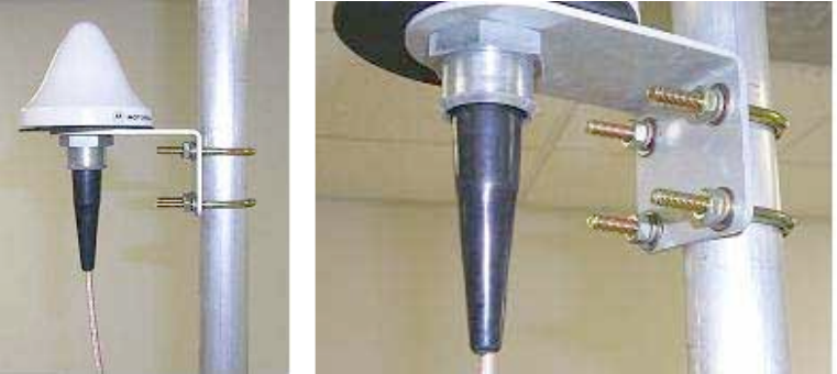
which the GPS antenna bracket can be mounted.
3. Place the U-bolts (provided) around the pole as shown in Figure 121.
4. Slide the GPS antenna bracket onto the U-bolts.
5. Slide the ring washers (provided) onto the U-bolts.
Release 8 Installation and Configuration Guide
Issue 2, November 2007 Draft 5 for Regulatory Review 335
6. Slide the lock washers (provided) onto the U-bolts.
7. Use the nuts (provided) to securely fasten the bracket to the U-bolts.
=========================== end of procedure ===========================
Figure 121: Detail of GPS antenna mounting
19.4.1 Recommended Materials for Cabling the GPS Antenna
The following materials are required for cabling the GPS antenna:
◦ up to 100 feet (30.4 meters) of LMR200 coaxial cable
◦ 2 Times Microwave N-male connectors (Times Microwave P/N TC-200-NM) or
equivalent connectors.
19.4.2 Cabling the GPS Antenna
Connect the GPS coax cable to the female N-connector on the GPS antenna.
19.5 INSTALLING A CMM2
Ensure that you comply with standard local or national electrical and climbing procedures
when you install the CMM2.
19.5.1 CMM2 Installation Temperature Range
Install the CMM2 outside only when temperatures are above –4° F (–20° C). The
bulkhead connector and the bushings and inserts in the bulkhead connector are rated for
the full –40° to +131° F (–40° to +55° C) range of the CMM2. However, for dynamic
operations (loosening, tightening, and inserting), they are compliant at, and rated for, only
temperatures at or above –4° F (–20° C).
19.5.2 Recommended Tools for Mounting a CMM2
The following tools may be needed for mounting the CMM2:
◦ 3/8” nut driver
◦ 12” adjustable wrench
◦ 14-mm wrench for pole-mounting
◦ needle-nose pliers
Release 8 Installation and Configuration Guide
Issue 2, November 2007 Draft 5 for Regulatory Review 336
19.5.3 Mounting a CMM2
Perform the following procedure to mount the CMM2.
Procedure 21: Mounting the CMM2
1. Ensure that the mounting position
◦ is not further than 328 feet (100 meters) of cable from the furthest AP or BH
that the CMM2 will serve.
◦ is not closer than 10 feet (3 meters) to the nearest AP or BH.
◦ is not further than 100 feet (30.4 meters) of cable from the intended mounting
position of the GPS antenna.
◦ allows you to fully open the door of the CMM2 for service.
2. Select a support structure to which the flanges of the CMM2 can be mounted.
3. If the support structure is a wall, use screws or bolts (neither is provided) to
attach the flanges to the wall.
4. If the support structure is an irregular-shaped object, use adjustable stainless
steel bands (provided) to attach the CMM2 to the object.
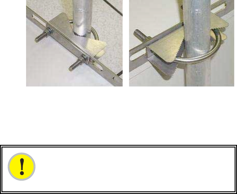
5. If the support structure is a pole that has an outside diameter of 3 to 8 cm, or
1.25 to 3 inches, use a toothed V-bracket (provided) to
a. attach the V-bracket to the pole as shown in Figure 122.
b. attach the CMM2 flanges to the V-bracket.
Figure 122: Detail of pole mounting
=========================== end of procedure ===========================
19.5.4 Cabling a CMM2
IMPORTANT!
Where you deploy CMM2s, one AP in each AP cluster must be connected to the
master port on the CMM2, and each module connected to a CMM2 must be
configured to Sync to Received Signal (Timing Port). If either is not done, then
the GPS receiver sends no sync pulse to the remaining ports.
Release 8 Installation and Configuration Guide
Issue 2, November 2007 Draft 5 for Regulatory Review 337
Perform the following procedure to attach the CMM2 cables on both ends:
Procedure 22: Cabling the CMM2
1. Carefully review the practices recommended in Best Practices for Cabling on
Page 182.
2. Remove the base cover from any AP or BH that is to be connected to this CMM2.
See Figure 46 on Page 178.
3. Remove the GPS sync cable knockout from the base cover.
4. For any AP that is to be connected to this CMM2, set the AP Sync Input
Configuration Page parameter to the Sync to Received Signal (Timing Port)
selection.
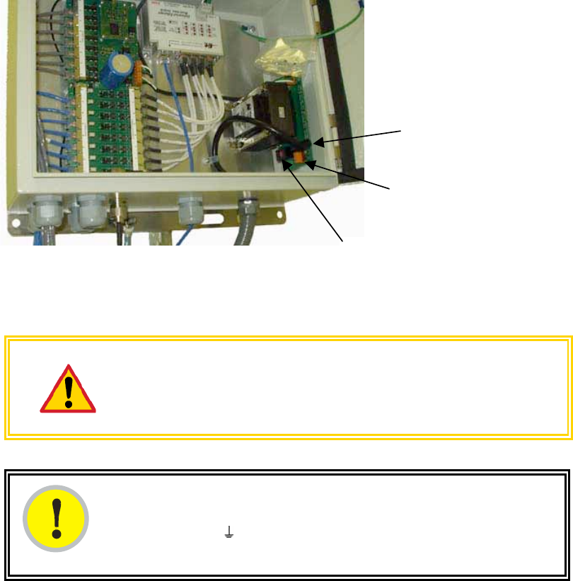
5. Review the schematic drawing inside the CMM2.
6. Set the 115-/230-volt switch in the CMM2 consistent with the power source. See
Figure 123.
115/230 V switch
AC power
connectors
Fuse receptacle
Figure 123: Location of 115-/230-volt switch
CAUTION!
Failure to set the 115-/230-volt switch correctly can result in damage to
equipment.
IMPORTANT!
The AC power connectors are labeled N for Neutral, L for Line, and PE for
Protective Earth (PE)
or ground. The maximum thickness of wire to be used is
4 mm2 or 12 AWG.
Release 8 Installation and Configuration Guide
Issue 2, November 2007 Draft 5 for Regulatory Review 338
7. Route the Ethernet cables from the APs and or BHs to the CMM2.
The strain relief plugs on the CMM2 have precut holes. Each hole of the strain
relief is designed to hold two CAT 5 UTP cables or one shielded cable. The
Ethernet cables have RJ-45 (standard Ethernet) connectors that mate to
corresponding ports inside the CMM2.
These ports are labeled J3. Eight J3 ports are available on the CMM2 to
accommodate any combination of APs and BHs.
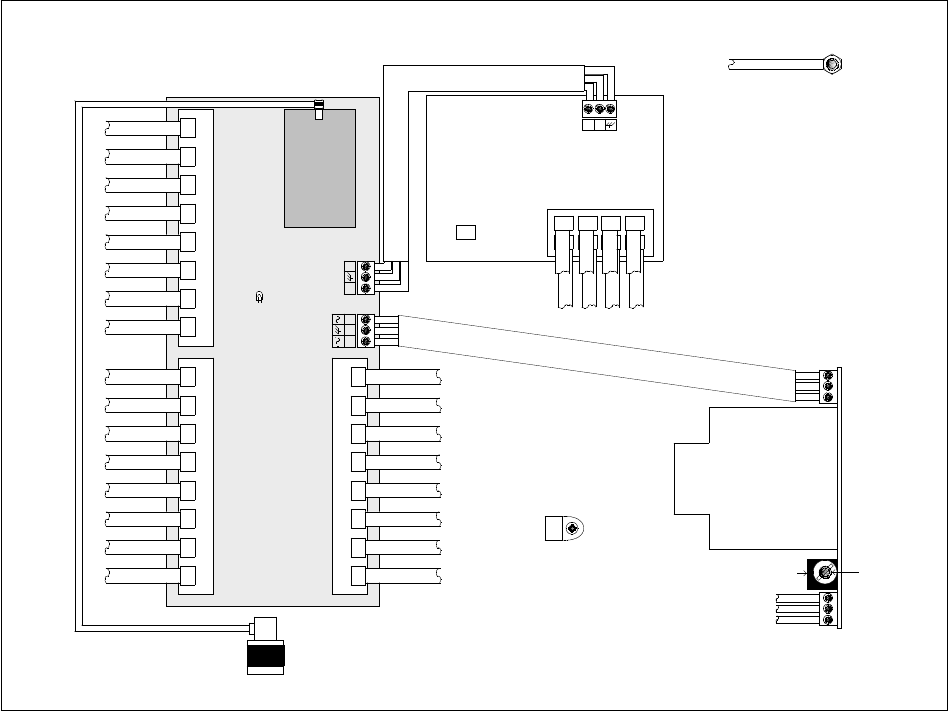
The logical connections in the CMM2 are displayed in Figure 124.
J3 GPS Sync
87654321
J1 Ethernet In
876 5 4 3 2 1
UPLINK PORT:
NON-CANOPY
ETHERNET
DEVICES
J2 Ethernet to Switch
87654
3
21
BLK
WHT
GRN
BLK
WHT
GRN
BLK
WHT
GRN
BLK
BT-0588
BLK
GRN
WHT
NEUTRAL
GROUND
HOT
TO AC
LINE
SOURCE
BT-0488-011TO DOOR GROUND
BT-0563-XXX
BT-0563-XXX
BT-0563-XXX
BT-0563-XXX
BT-0563-XXX
BT-0563-XXX
BT-0563-XXX
BT-0563-XXX
BT-0562-XXX
BT-0562-XXX
BT-0562-XXX
BT-0562-XXX
BT-0562-XXX
BT-0562-XXX
BT-0562-XXX
BT-0562-XXX
TO AP GPS
TO AP ETHERNET
ETHERNET SWITCH PORTS
BT-0556-008
BT-0556-008
BT-0556-008
BT-0556-008
BT-0556-008
BT-0556-008
BT-0556-008
BT-0556-008
TO ETHERNET SWICTH
BT-0556-008
BT-0556-008
BT-0556-008
BT-0556-008
BT-0556-008
BT-0556-008
BT-0556-008
BT-0556-008
TO J2
TO GPS
ANTENNA
BT-0555-023
Interconnect Board
GPS
Receiver
Power Supply
Strain relief strap for
incoming power wiring
WARNING: DISCONNECT ALL POWER BEFORE SERVICING
+-
+ -
115/230V Switch Replace Fuse with
Type FSM 3.15A
+ - +
BT-0588
Remove lines from power supply if using external DC supply
Master
PWR LED
Figure 124: Layout of logical connections in CMM2
8. Connect the Ethernet cable from the first AP or BH to the Port 1 in the J3 ports in
the CMM2. This port is the master Ethernet port for the CMM2 and should be
connected first in all cases. Figure 125 on Page 339 is a photograph of a
properly wired CMM2.
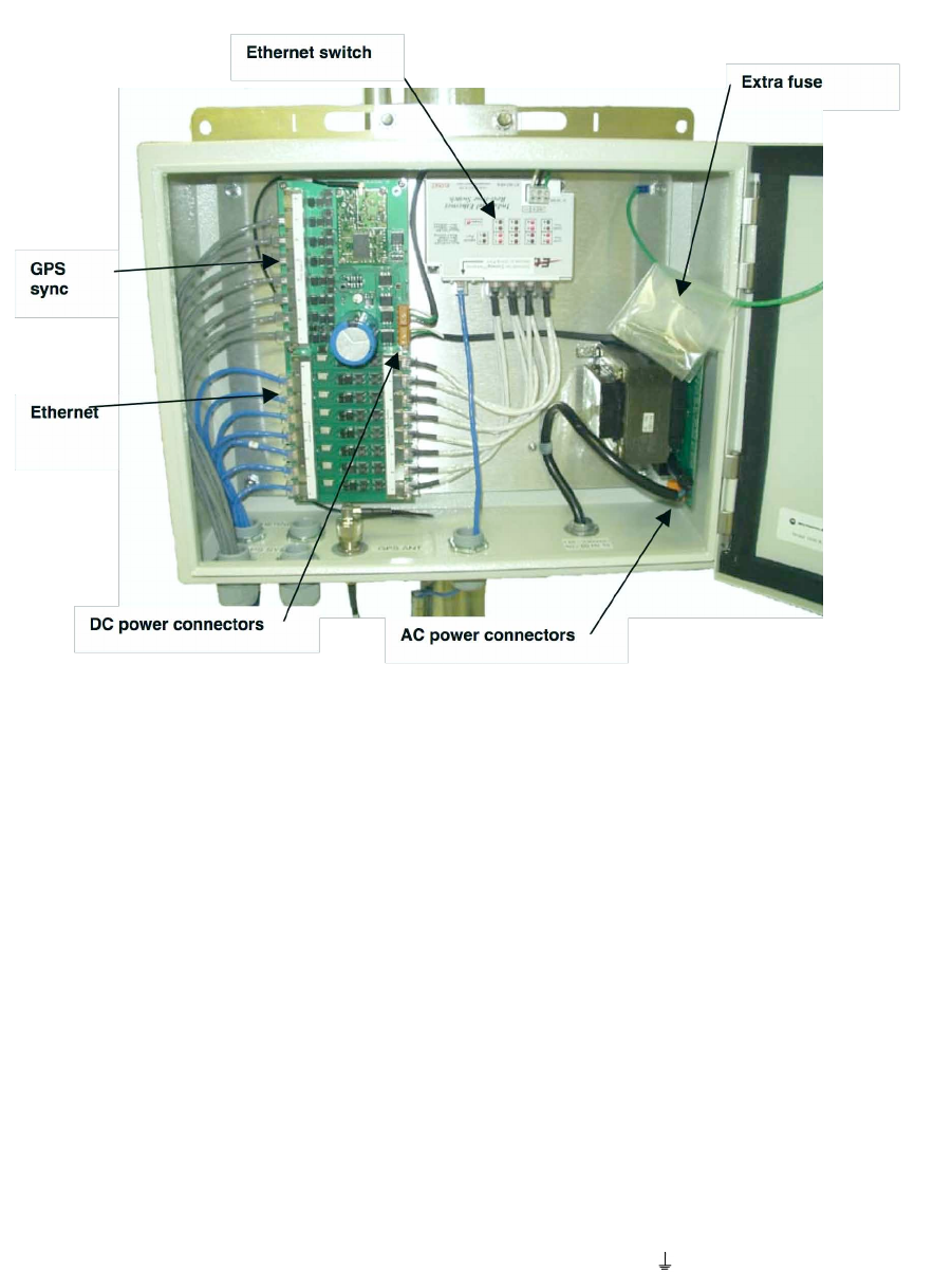
Release 8 Installation and Configuration Guide
Issue 2, November 2007 Draft 5 for Regulatory Review 339
Figure 125: Canopy CMM2, front view
9. Connect the remaining Ethernet cables to the remaining J3 ports.
10. Route the GPS sync (serial) cables from the APs to the CMM2.
The GPS sync cables have 6-conductor RJ-11 connectors that mate to
corresponding ports inside the CMM2.
These ports are labeled J1. Eight J1 ports are available on the CMM2 to
accommodate any combination of APs and BHs.
11. Connect the GPS sync cable from the first AP or BH to the Port 1 in the J1 ports
in the CMM2. See Figure 125 on Page 339.
This port is the master GPS sync port for the CMM2 and should be connected
first in all cases. This is necessary to initialize the GPS on the CMM2.
12. Connect the remaining GPS sync cables to the remaining J1 ports.
13. If this CMM2 requires network connection, perform the following steps:
a. Route a network cable into the CMM2.
b. Connect to the uplink port on the switch.
c. Properly ground (connect to Protective Earth [PE]
) the Ethernet cable. The
Canopy Surge Suppressor provides proper grounding for this situation.
NOTE: Instructions for installing a Canopy Surge Suppressor are provided in
Procedure 28 on Page 344.
Release 8 Installation and Configuration Guide
Issue 2, November 2007 Draft 5 for Regulatory Review 340
14. Connect GPS coaxial cable to the N-connector on the outside of the CMM2. See
Figure 47 on Page 180.
15. Connect AC or DC power to the CMM2, consistent with Figure 124 on Page 338.
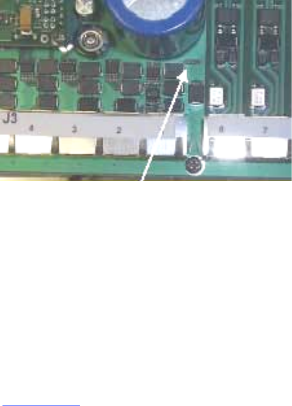
NOTE: When power is applied, the following indicators are lighted:
◦ the power LED on the Ethernet switch
◦ the green LED on the circuit board, as shown in Figure 126.
Figure 126: Port indicator LED on Ethernet switch
16. Verify that each port indicator LED on the Ethernet switch is lit (each AP or BH is
reliably connected to the Ethernet switch).
17. Replace the base cover on each AP or BH.
18. Close and lock the CMM2.
=========================== end of procedure ===========================
19.5.5 Verifying CMM2 Connections
To verify the CMM2 connections after the APs and or BHs have been installed, perform
the following steps:
Procedure 23: Verifying CMM2 connections
1. Access the web-based interface for each AP or BHM by opening
http://<ip-address>, where the <ip-address> is the address of the individual
module.
2. In the General Status tab of the Home page, verify that the System Time field
displays the time in GMT.
=========================== end of procedure ===========================
19.6 INSTALLING A CMMmicro
Ensure that you comply with standard local or national electrical and climbing procedures
when you install the CMMmicro.
Release 8 Installation and Configuration Guide
Issue 2, November 2007 Draft 5 for Regulatory Review 341
19.6.1 CMMmicro Temperature Range
Install the CMMmicro outside only when temperatures are above –4° F (–20° C). The
bulkhead connector and the bushings and inserts in the bulkhead connector are rated for
the full –40° to +131° F (–40° to +55° C) range of the CMMmicro. However, for dynamic
operations (loosening, tightening, and inserting), they are compliant at, and rated for, only
temperatures at or above –4° F (–20° C).
19.6.2 Recommended Tools for Mounting a CMMmicro
The following tools may be needed during installation:
◦ 3/8” nut driver
◦ 12” adjustable wrench
◦ 14-mm wrench for installation of pole-mounting brackets
◦ needle-nose pliers
19.6.3 Mounting a CMMmicro
Perform the following procedure to mount the CMMmicro.
Procedure 24: Mounting the CMMmicro
1. Ensure that the mounting position
◦ is not further than 328 feet (100 meters) from the furthest AP or BH that the
CMMmicro will serve.
◦ is not closer than 10 feet (3 meters) to the nearest AP or BH.
◦ is not further than 100 feet (30.5 meters) of cable from the intended mounting
position of the GPS antenna.
◦ allows you to fully open the door for service.
2. Select a support structure to which the flanges can be mounted.
3. If the support structure is a wall, use screws or bolts (neither is provided) to
attach the flanges to the wall.
If the support structure is an irregular-shaped object, use adjustable stainless
steel bands (provided) to attach the CMMmicro to the object.
4. If the support structure is a pole that has an outside diameter of 1.25 to 3 inches
(3 to 8 cm), use a toothed V-bracket (provided) to
d. attach the V-bracket to the pole as shown in Figure 122 on Page 336.
e. attach the CMMmicro flanges to the V-bracket.
=========================== end of procedure ===========================
19.6.4 Installing the Power Supply for the CMMmicro
Install the CMMmicro power converter in only a hut, wiring closet, or weatherized NEMA-
approved enclosure. This is imperative to keep moisture away from the power converter,
not to shield it from harsh temperatures.
Release 8 Installation and Configuration Guide
Issue 2, November 2007 Draft 5 for Regulatory Review 342
WARNING!
Although the output of the power converter is 24 V, the 100-W power rating
classifies the converter as a Class 2 electric device. For this reason, whenever
you work on power in the CMMmicro, you must first disconnect the DC converter
from the AC power source.
Perform the following procedure to install the provided power supply.
Procedure 25: Installing the Power Supply for the CMMmicro
1. Connect the 6-ft (2-m) AC power cord to the power converter (but not yet to an
AC receptacle).
2. Select the length of power cord as follows:
a. If either mounting the unit inside with the power converter or outside within 9
ft (2.8 m) of the power converter, select the 10-ft (3-m) DC power cord (rated
for outdoor use).
b. If mounting the unit outside and further than 9 ft (2.8 m) from the power
converter, ensure that this additional length of cord is either UV-resistant or
shielded from UV rays.
◦ use a terminal block, connector, or splice to add the additional length.
◦ protect the terminal block, connector, or splice (as inside a weatherized
enclosure, for example).
Table 51: Wire size for CMMmicro power runs of longer than 9 feet (2.8 m)
DC Power Cord Length
Proper Wire Size
9−90 ft (3−25 m)
12 AWG (4 mm2)
91−145 ft (26−45 m)
10 AWG (6 mm2)
146−230 ft (46−70 m)
8 AWG (10 mm2)
>230 ft (>70 m)
6 AWG (16 mm2)
3. Refer to Figure 70: CMMmicro connections on Page 220.
4. Feed the power cord through the bulkhead connector of the CMMmicro.
5. Connect the converter lead whose insulation has a white stripe to +V on the
CMMmicro terminal block.
6. Connect the converter lead whose insulation is solid black to −V on the
CMMmicro terminal block.
=========================== end of procedure ===========================
19.6.5 Cabling a CMMmicro
Perform the following procedure to attach the CMMmicro cables on both ends:
Procedure 26: Cabling the CMMmicro
1. Remove the base cover from any AP or BH that is to be connected to this
CMMmicro. See Figure 46 on Page 178.

Release 8 Installation and Configuration Guide
Issue 2, November 2007 Draft 5 for Regulatory Review 343
2. Review the schematic drawing inside the CMMmicro and see
Figure 70: CMMmicro connections on Page 220.
3. Note that the inserts in the bulkhead connector bushings have precut holes.
4. Remove the hard silicon spacer.
5. Route the Ethernet cables from the APs through the bulkhead connectors to the
Ethernet switch inside the CMMmicro.
6. If the BH at this site is a 30/60- or 150/300-Mbps BH
a. connect the BH outdoor unit (ODU) to the ODU port of the power indoor unit
(PIDU).
b. connect the PIDU to an unpowered port of the CMMmicro.
If the BH is of another modulation rate, route the Ethernet cables from the BH
through the bulkhead connectors to the Ethernet switch in the CMMmicro.
7. If the site has a wired network feed, route the cable into the CMMmicro and
connect it to an unpowered port on the switch.
8. Mount a Canopy surge suppressor at a low point of the network feed and
connect the surge suppressor to solid ground.
9. On the door label, record the MAC and IP addresses of the CMMmicro and all
connected equipment.
10. Consistent with practices in your company, note the above information to add
later to the company equipment database.
11. Connect the GPS coax cable from the GPS antenna to the female BNC
connector in the CMMmicro.
12. If this CMMmicro requires network connection, perform the following steps:
a. Route a network cable into the CMMmicro.
b. Connect to the uplink port on the switch.
c. Properly ground (connect to Protective Earth [PE]
) the Ethernet cable. The
Canopy Surge Suppressor provides proper grounding for this situation.
NOTE: Instructions for installing a Canopy Surge Suppressor are provided as
part of Procedure 28 on Page 344.
13. Connect the DC power cable to the CMMmicro.
14. Plug the DC converter into an AC receptacle.
15. Verify that the LEDs light.
=========================== end of procedure ===========================
19.6.6 Verifying CMMmicro Connections
To verify the CMMmicro connections after the APs and or BHs have been installed,
perform the following steps.
Procedure 27: Verifying CMMmicro connections
1. Access the web-based interface for each AP or BH by opening
http://<ip-address>, where the <ip-address> is the address of the individual
module.
2. In the Status page, verify that the time is expressed in GMT.
3. In the menu on the left-hand side of the web page, click on GPS Status.
4. Verify that the AP or BH is seeing and tracking satellites. (To generate the timing
pulse, the module must track at least 4 satellites.)
Release 8 Installation and Configuration Guide
Issue 2, November 2007 Draft 5 for Regulatory Review 344
=========================== end of procedure ===========================
19.7 INSTALLING AN SM
Installing a Canopy SM consists of two procedures:
◦ Physically installing the SM on a residence or other location and performing a
course alignment using the alignment tone (Procedure 28).
◦ Verifying the AP to SM link and finalizing alignment using review of power level
and jitter, link tests, and review of registration and session counts (Procedure 29
on Page 347).
Procedure 28: Installing the SM
1. Choose the best mounting location for the SM.
2. Select the type of mounting hardware appropriate for this location. (For mounting
2.4, 5.2, 5.4, and 5.7 GHz SMs, Motorola offers the SMMB-1 mounting bracket.
For mounting 900 MHz SMs, Motorola offers the SMMB-2 mounting bracket.)
3. Remove the base cover of the SM. (See Figure 46 on Page 178.)
4. Terminate the UV outside grade Category 5 Ethernet cable with an RJ-45
connector, and connect the cable to the SM. (See Procedure 8 on Page 192.)
5. Optionally, attach the SM to the arm of the Canopy Passive Reflector dish
assembly as shown in Figure 127.
RECOMMENDATION:
A reflector in this instance reduces the beamwidth to reduce
interference. The arm is molded to receive and properly aim the
module relative to the aim of the dish. Use stainless steel hose
clamps for the attachment.
Stainless steel
hose clamps
Reflector dish arm
Figure 127: SM attachment to reflector arm
Release 8 Installation and Configuration Guide
Issue 2, November 2007 Draft 5 for Regulatory Review 345
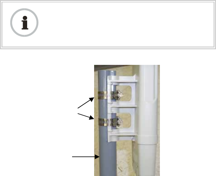
6. Use stainless steel hose clamps or equivalent fasteners to lock the SM into
position.
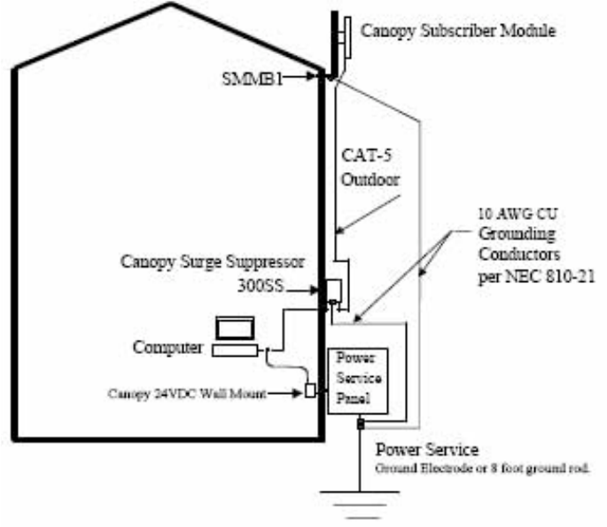
NOTE: The SM grounding method is shown in Figure 128.
Figure 128: SM grounding per NEC specifications
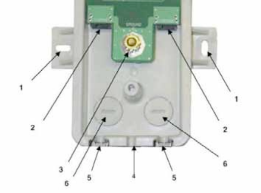
7. Remove the cover of the 300SS Surge Suppressor.
Release 8 Installation and Configuration Guide
Issue 2, November 2007 Draft 5 for Regulatory Review 346
KEY TO CALLOUTS
1
Holes—for mounting the Surge Suppressor to a flat surface (such
as an outside wall). The distance between centers is 4.25 inches
(108 mm).
2
RJ-45 connectors—One side (neither side is better than the other
for this purpose) connects to the Canopy product (AP, SM, BHM,
BHS, or cluster management module). The other connects to the
AC adaptor’s Ethernet connector.
3
Ground post—use heavy gauge (10 AWG or 6 mm2) copper wire
for connection. Refer to local electrical codes for exact
specifications.
4
Ground Cable Opening—route the 10 AWG (6 mm2) ground
cable through this opening.
5
CAT-5 Cable Knockouts—route the two CAT-5 cables through
these openings, or alternatively through the Conduit Knockouts.
6
Conduit Knockouts—on the back of the case, near the bottom.
Available for installations where cable is routed through
building conduit.
Figure 129: Internal view of Canopy 300SS Surge Suppressor
8. With the cable openings facing downward, mount the 300SS to the outside of the
subscriber premises, as close to the point where the Ethernet cable penetrates
the residence or building as possible, and as close to the grounding system
(Protective Earth) as possible.
9. Using diagonal cutters or long nose pliers, remove the knockouts that cover the
cable openings to the 300SS.
10. Connect an Ethernet cable from the power adapter (located inside the residence
or building, outward through the building penetration) to either RJ-45 port of the
300SS.
11. Connect another Ethernet cable from the other RJ-45 port of the 300SS to the
Ethernet port of the SM.
12. Refer to Grounding SMs on Page 172.
13. Wrap an AWG 10 (or 6mm2) copper wire around the Ground post of the 300SS.
Release 8 Installation and Configuration Guide
Issue 2, November 2007 Draft 5 for Regulatory Review 347
14. Tighten the Ground post locking nut in the 300SS onto the copper wire.
15. Securely connect the copper wire to the grounding system (Protective Earth)
according to applicable regulations.
16. Connect a ground wire to the 300SS.
17. Replace the cover of the 300SS surge suppressor.
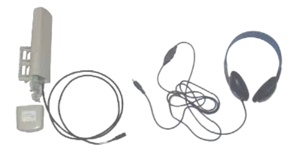
18. For coarse alignment of the SM, use the Audible Alignment Tone feature as
follows:
a. Set the 2X Rate parameter in the SM to Disable.
b. At the SM, connect the RJ-11 6-pin connector of the Alignment Tool Headset
to the RJ-11 utility port of the SM.
Alternatively, instead of using the Alignment Tool Headset, use an earpiece
or small battery-powered speaker connected to Pin 5 (alignment tone output)
and Pin 6 (ground) of an RJ-11 connector.
c. Listen to the alignment tone for
◦ pitch, which indicates greater signal power (RSSI/dBm) by higher
pitch.
◦ volume, which indicates better signal quality (lower jitter) by higher
volume.
Figure 130: Audible Alignment Tone kit, including headset and connecting
cable
d. Adjust the module slightly until you hear the highest pitch and highest
volume.
e. If the Configuration web page of the SM contains a 2X Rate parameter, set it
back to Enable.
19. When you have achieved the best signal (highest pitch, loudest volume), lock the
SM in place with the mounting hardware.
=========================== end of procedure ===========================
19.8 VERIFYING AN AP-SM LINK
To verify the AP-SM link after the SM has been installed, perform the following steps.
Procedure 29: Verifying performance for an AP-SM link
Release 8 Installation and Configuration Guide
Issue 2, November 2007 Draft 5 for Regulatory Review 348
1. Using a computer (laptop, desktop, PDA) connected to the SM, open a browser
and access the SM using the default IP address of http://169.254.1.1 (or the IP
address configured in the SM, if one has been configured.)
2. On the General Status tab of the Home page in the SM (shown in Figure 60 on
Page 198), look for Power Level and Jitter.
IMPORTANT: The received Power Level is shown in dBm and should be
maximized. Jitter should be minimized. However, better/lower jitter should be
favored over better/higher dBm. For example, if coarse alignment gives an SM
a power level of −75 dBm and a jitter measurement of 5, and further refining
the alignment drops the power level to −78 dBm and the jitter to 2 or 3, the latter
would be better, with the following caveats:
◦ When the receiving link is operating at 1X, the Jitter scale is 0 to 15 with
desired jitter between 0 and 4.
◦ When the receiving link is operating at 2X, the Jitter scale is 0 to 15 with
desired jitter between 0 and 9.
NOTE:
For historical reasons, RSSI is also shown and is the unitless
measure of power. The best practice is to use Power Level and
ignore RSSI, which implies more accuracy and precision than is
inherent in the measurement.
3. Fine-adjust the SM mounting, if needed, to improve Jitter or Power Level.
4. Click the Link Capacity Test tab of the Tools web page in the SM.
NOTE: Use of this tool is described under Using the Link Capacity Test Tool (All)
on Page 432.
5. Perform several link tests of 10-second duration as follows:
a. Type into the Duration field how long (in seconds) the RF link should be
tested.
b. Leave the Packet Length field (when present) set to the default of 1522
bytes or type into that field the packet length at which you want the test
conducted.
c. Leave the Number of Packets field set to 0 (to flood the link).
d. Click the Start Test button.
e. View the results of the test.
6. If these link tests fail to consistently show 90% or greater efficiency in 1X
operation or 50 to 60% efficiency in 2X, troubleshoot the link, using the data as
follows:
◦ If the downlink is consistently 90% efficient, but the uplink is only 40%, this
indicates trouble for the SM transmitting to the AP. Have link tests performed
for nearby SMs. If their results are similar, investigate a possible source of
interference local at the AP.
◦ If the uplink is consistently 90% efficient, but the downlink is only 40%, this
indicates trouble for the AP transmitting to the SM. Investigate a possible
source of interference near the SM.
If these link tests consistently show 90% or greater efficiency in 1X operation, or
50 to 60% efficiency in 2X operation, in both uplink and downlink, continue this
procedure.
Release 8 Installation and Configuration Guide
Issue 2, November 2007 Draft 5 for Regulatory Review 349
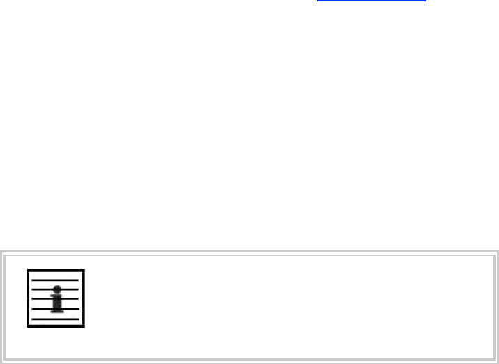
7. Open the Session Status tab in the Home page of the AP.
NOTE: An example of this page is shown in Figure 131.
Figure 131: AP/SM link status indications in the AP Session Status tab
8. Find the Session Count line under the MAC address of the SM.
Release 8 Installation and Configuration Guide
Issue 2, November 2007 Draft 5 for Regulatory Review 350
9. Check and note the values for Session Count, Reg Count, and Re-Reg Count.
10. Briefly monitor these values, occasionally refreshing this page by clicking another
tab and then the Session Status tab again.
11. If these values are low (for example, 1, 1, and 0, respectively, meaning that
the SM registered and started a stable session once) and not changing
a. consider the installation successful.
b. monitor these values from the network office over the next several hours and
days.
If these values are greater than 1, 1, and 0, or they increase while you are
monitoring them, troubleshoot the link. (For example, recheck jitter as described
in Procedure 28: Installing the SM or recheck link efficiency as described in this
procedure, then look for sources of RF interference or obstructions.)
=========================== end of procedure ===========================
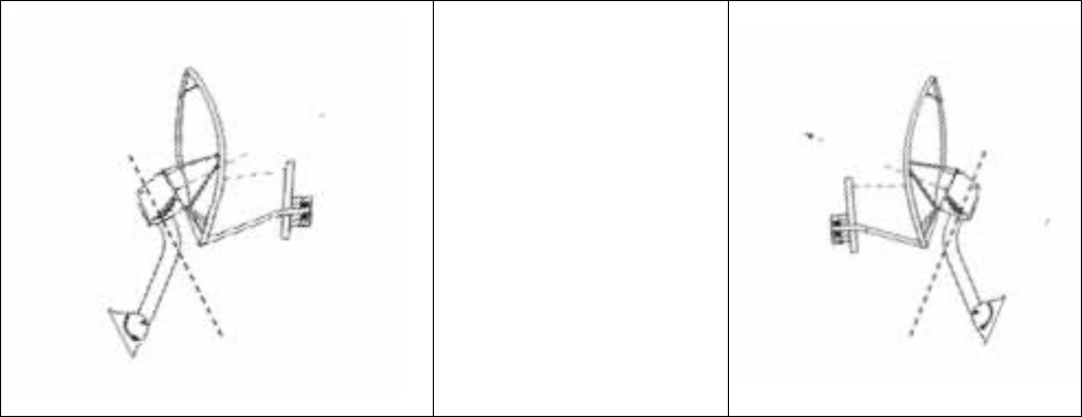
19.9 INSTALLING A REFLECTOR DISH
The internal patch antenna of the module illuminates the Canopy Passive Reflector Dish
from an offset position. The module support tube provides the proper angle for this offset.
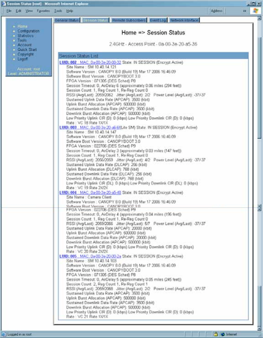
19.9.1 Both Modules Mounted at Same Elevation
For cases where the other module in the link is mounted at the same elevation, fasten the
mounting hardware leg of the support tube vertical for each module. When the hardware
leg is in this position
◦ the reflector dish has an obvious downward tilt.
◦ the module leg of the support tube is not vertical.
For a mount to a non-vertical structure such as a tapered tower, use a plumb line to
ensure that the hardware leg is vertical when fastened. Proper dish, tube, and module
positions for a link in this case are illustrated in Figure 132. The dish is tipped forward,
not vertical, but the focus of the signal is horizontal.
--------------------------------------------EARTH--------------------------------------------
Figure 132: Correct mount with reflector dish
Release 8 Installation and Configuration Guide
Issue 2, November 2007 Draft 5 for Regulatory Review 351
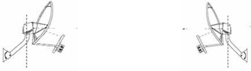
Improper dish, tube, and module positions for this case are illustrated in Figure 133.
--------------------------------------------EARTH--------------------------------------------
Figure 133: Incorrect mount with reflector dish
19.9.2 Modules Mounted at Different Elevations
For cases where the other module in the link is mounted at a different elevation, the
assembly hardware allows tilt adjustment. The proper angle of tilt can be calculated as a
factor of both the difference in elevation and the distance that the link spans. Even in this
case, a plumb line and a protractor can be helpful to ensure the proper tilt. This tilt is
typically minimal.
The number of degrees to offset (from vertical) the mounting hardware leg of the support
tube is equal to the angle of elevation from the lower module to the higher module (b in
the example provided in Figure 34 on Page 145).
19.9.3 Mounting Assembly
Both the hardware that Mounting Assembly 27RD provides for adjustment and the
relationship between the offset angle of the module and the direction of the beam are
illustrated in Figure 134.
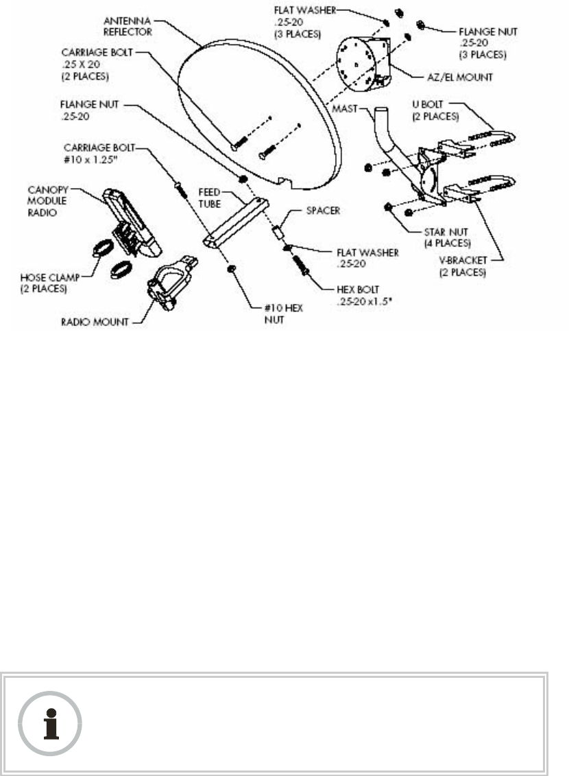
Release 8 Installation and Configuration Guide
Issue 2, November 2007 Draft 5 for Regulatory Review 352
Figure 134: Mounting assembly, exploded view
19.10 INSTALLING A BH TIMING MASTER
To install the Canopy BHM, perform the following steps:
Procedure 30: Installing the BHM
1. Access the General tab of the Configuration page in the BHM.
2. If this is a 20-Mbps BH, set the 2X Rate parameter to Disabled (temporarily for
easier course aiming).
3. Click the Save Changes button.
4. Click the Reboot button.
5. After the reboot is completed, remove power from the BHM.
6. Choose the best mounting location for your particular application.
7. Attach the BHM to the arm of the Canopy Passive Reflector dish assembly as
shown in Figure 135.
RECOMMENDATION:
The arm is molded to receive and properly aim the module relative to the aim of
the dish. ( See Figure 132 on Page 350.) Stainless steel hose clamps should be
used for the attachment.
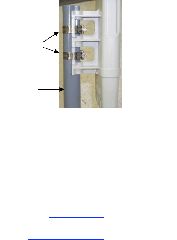
Release 8 Installation and Configuration Guide
Issue 2, November 2007 Draft 5 for Regulatory Review 353
Stainless steel
hose clamps
Reflector dish arm
Figure 135: BH attachment to reflector arm
8. Align the BHM as follows:
a. Move the module to where the link will be unobstructed by the radio horizon
and no objects penetrate the Fresnel zone. (The Canopy System Calculator
page AntennaElevationCalcPage.xls automatically calculates the minimum
antenna elevation that is required to extend the radio horizon to the other end
of the link. The Canopy System Calculator page FresnelZoneCalcPage.xls
automatically calculates the Fresnel zone clearance that is required between
the visual line of sight and the top of a high-elevation object.)
b. Use a local map, compass, and/or GPS device as needed to determine the
direction to the BHS.
c. Apply the appropriate degree of downward or upward tilt. (The Canopy
System Calculator page DowntiltCalcPage.xls automatically calculates the
angle of antenna downward tilt that is required.)
d. Ensure that the BHS is within the beam coverage area. (The Canopy System
Calculator page BeamwidthRadiiCalcPage.xls automatically calculates the
radii of the beam coverage area.)
9. Using stainless steel hose clamps or equivalent fasteners, lock the BHM into
position.
10. Remove the base cover of the BHM. (See Figure 46 on Page 178.)
11. If this BHM will not be connected to a CMMmicro, optionally connect a utility
cable to a GPS timing source and then to the RJ-11 port of the BHM.
12. Either connect the BHM to the CMM or connect the DC power converter to the
BHM and then to an AC power source.
RESULT: When power is applied to a Canopy module or the unit is reset on the
web-based interface, the module requires approximately 25 seconds to boot.
During this interval, self-tests and other diagnostics are being performed.
13. Access the General tab of the Configuration page of this BHM.
14. If the CMM is a CMMmicro, set the Sync Input parameter to the Sync
to Received Signal (Power Port) selection.
If the CMM is a CMM2, set the Sync Input parameter to the Sync to Received
Signal (Timing Port) selection.
=========================== end of procedure ===========================

Release 8 Installation and Configuration Guide
Issue 2, November 2007 Draft 5 for Regulatory Review 354
19.11 INSTALLING A BH TIMING SLAVE
Installing a Canopy BHS consists of two procedures:
◦ Physically installing the BHS and performing a course alignment using the
alignment tone (Procedure 31).
◦ Verifying the BH link and finalizing alignment using review of power level and
jitter, link tests, and review of registration and session counts (Procedure 32 on
Page 355).
Procedure 31: Installing the BHS
1. Choose the best mounting location for the BHS.
2. Remove the base cover of the BHS. (See Figure 46 on Page 178.)
3. Terminate the UV outside grade Category 5 Ethernet cable with an RJ-45
connector, and connect the cable to the BHS. (See Procedure 8 on Page 192.)
4. Attach the BHS to the arm of the Canopy Passive Reflector dish assembly as
shown in Figure 127 on Page 344.
RECOMMENDATION:
The arm is molded to receive and properly aim the BH relative to the
aim of the dish. Use stainless steel hose clamps for the attachment.
5. Use stainless steel hose clamps or equivalent fasteners to lock the BHS into
position.
6. Remove the cover of the 300SS Surge Suppressor.
7. With the cable openings facing downward, mount the 300SS as close to the
grounding system (Protective Earth) as possible.
8. Using diagonal cutters or long nose pliers, remove the knockouts that cover the
cable openings to the 300SS.
9. Connect an Ethernet cable from the power adapter to either RJ-45 port of the
300SS.
10. Connect another Ethernet cable from the other RJ-45 port of the 300SS to the
Ethernet port of the BHS.
11. Refer to Grounding SMs on Page 172.
12. Wrap an AWG 10 (or 6mm2) copper wire around the Ground post of the 300SS.
13. Tighten the Ground post locking nut in the 300SS onto the copper wire.
14. Securely connect the copper wire to the grounding system (Protective Earth)
according to applicable regulations.
15. Connect a ground wire to the 300SS.
16. Replace the cover of the 300SS surge suppressor.
17. For coarse alignment of the BHS, use the Audible Alignment Tone feature as
follows:
a. If the Configuration web page of the BHS contains a 2X Rate parameter, set
it to Disable.

Release 8 Installation and Configuration Guide
Issue 2, November 2007 Draft 5 for Regulatory Review 355
b. At the BHS, connect the RJ-11 6-pin connector of the Alignment Tool
Headset (shown in Figure 130 on Page 347) to the RJ-11 utility port of the
SM.
Alternatively, instead of using the Alignment Tool Headset, use an earpiece
or small battery-powered speaker connected to Pin 5 (alignment tone output)
and Pin 6 (ground) of an RJ-11 connector.
c. Listen to the alignment tone for
◦ pitch, which indicates greater signal power (RSSI/dBm) by higher
pitch.
◦ volume, which indicates better signal quality (lower jitter) by higher
volume.
d. Adjust the module slightly until you hear the highest pitch and highest
volume.
e. If the Configuration web page of the BHS contains a 2X Rate parameter, set
it back to Enable.
18. When you have achieved the best signal (highest pitch, loudest volume), lock the
BHS in place with the mounting hardware.
=========================== end of procedure ===========================
19.12 UPGRADING A BH LINK TO BH20
To replace a pair of 10-Mbps BHs with 20-Mbps BHs, you can minimize downtime by
temporarily using the 10-Mbps capability in the faster modules. However, both
interference and differences in receiver sensitivity can make alignment and link
maintenance more difficult than in the previous 10-Mbps link. The effects of these factors
are greater at greater link distances, particularly at 5 miles or more.
In shorter spans, these factors may not be prohibitive. For these cases, set the first
replacement module to 1X Rate and establish the link to the 10-Mbps BH on the far end.
Similarly, set the second replacement module to 1X Rate and re-establish the link. With
both of the faster modules in place and with an operational link having been achieved,
reset their modulation to 2X Rate (20 Mbps).
19.13 VERIFYING A BH LINK
To verify the backhaul link after the BHS has been installed, perform the following steps.
Procedure 32: Verifying performance for a BH link
1. Using a computer (laptop, desktop, PDA) connected to the BHS, open a browser
and access the BHS using the default IP address of http://169.254.1.1 (or the IP
address configured in the BHS, if one has been configured.)
2. On the General Status tab of the Home page in the BHS (shown in Figure 65 on
Page 210), look for Power Level and Jitter.
IMPORTANT: The received Power Level is shown in dBm and should be
maximized. Jitter should be minimized. However, better/lower jitter should be
favored over better/higher dBm. For example, if coarse alignment gives a BHS
a power level of −75 dBm and a jitter measurement of 5, and further refining
the alignment drops the power level to −78 dBm and the jitter to 2 or 3, the latter
would be better, with the following caveats:
◦ When the receiving link is operating at 1X, the Jitter scale is 0 to 15 with
desired jitter between 0 and 4.

Release 8 Installation and Configuration Guide
Issue 2, November 2007 Draft 5 for Regulatory Review 356
◦ When the receiving link is operating at 2X, the Jitter scale is 0 to 15 with
desired jitter between 0 and 9.
NOTE:
For historical reasons, RSSI is also shown and is the unitless
measure of power. The best practice is to use Power Level and
ignore RSSI, which implies more accuracy and precision than is
inherent in its measurement.
3. Fine-adjust the BHS mounting, if needed, to improve Jitter or Power Level.
4. Click the Link Capacity Test tab of the Tools web page in the BHS.
NOTE: Use of this tool is described under Using the Link Capacity Test Tool (All)
on Page 432.
5. Perform several link tests of 10-second duration as follows:
a. Type into the Duration field how long (in seconds) the RF link should be
tested.
b. Leave the Packet Length field (when present) set to the default of 1522
bytes or type into that field the packet length at which you want the test
conducted.
c. Leave the Number of Packets field set to 0 (to flood the link).
d. Click the Start Test button.
e. View the results of the test.
6. If these link tests fail to consistently show 90% or greater efficiency in 1X
operation or 50 to 60% efficiency in 2X, troubleshoot the link, using the data as
follows:
◦ If the downlink is consistently 90% efficient, but the uplink is only 40%, this
indicates trouble for the BHS transmitting to the BHM. Investigate a possible
source of interference near the BHM.
◦ If the uplink is consistently 90% efficient, but the downlink is only 40%, this
indicates trouble for the BHM transmitting to the BHS. Investigate a possible
source of interference near the BHS.
If these link tests consistently show 90% or greater efficiency in 1X operation, or
50 to 60% efficiency in 2X operation, in both uplink and downlink, continue this
procedure.
7. Open the Session Status tab in the Home page of the BHM.
NOTE: An example of this page is shown in Figure 136.
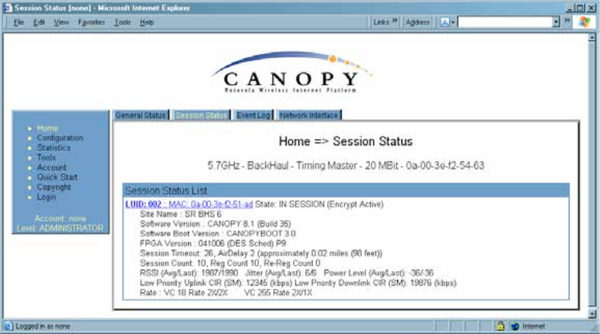
Release 8 Installation and Configuration Guide
Issue 2, November 2007 Draft 5 for Regulatory Review 357
Figure 136: Session Status tab of BHM
8. Find the Session Count line under the MAC address of the BHS.
9. Check and note the values for Session Count, Reg Count, and Re-Reg Count.
10. Briefly monitor these values, occasionally refreshing this page by clicking another
tab and then the Session Status tab again.
11. If these values are low (for example, 1, 1, and 0, respectively, meaning that
the BHS registered and started a stable session once) and not changing
a. consider the installation successful.
b. monitor these values from the network office over the next several hours and
days.
If these values are greater than 1, 1, and 0, or they increase while you are
monitoring them, troubleshoot the link. (For example, recheck jitter as described
in Procedure 28: Installing the SM or recheck link efficiency as described in this
procedure, then look for sources of RF interference or obstructions.)
=========================== end of procedure ===========================
Release 8 Installation and Configuration Guide
Issue 2, November 2007 Draft 5 for Regulatory Review 359
20 VERIFYING SYSTEM FUNCTIONALITY
To verify system functionality after the APs and or BHs have been installed, perform the
following steps.
Procedure 33: Verifying system functionality
1. For each installed AP, use a computer or PDA connected to an SM set to a
compatible configuration (frequency and color code, for example) and verify link
functionality.
2. For each BH installed, use a notebook computer connected to a BH (BHM or
BHS, as appropriate) set to a compatible configuration and verify link
functionality.
3. If a network data feed is present and operational, use an SM or BHS to verify
network functionality.
=========================== end of procedure ===========================

Release 8 Operations Guide
Issue 2, November 2007 Draft 5 for Regulatory Review 361
O
O
OP
P
PE
E
ER
R
RA
A
AT
T
TI
I
IO
O
ON
N
NS
S
S
G
G
GU
U
UI
I
ID
D
DE
E
E
Release 8 Operations Guide
Issue 2, November 2007 Draft 5 for Regulatory Review 363
21 GROWING YOUR NETWORK
Keys to successfully growing your network include
◦ monitoring the RF environment.
◦ considering software release compatibility.
◦ redeploying modules appropriately and quickly.
21.1 MONITORING THE RF ENVIRONMENT
Regardless of whether you are maintaining or growing your network, you may encounter
new RF traffic that can interfere with your current or planned equipment. Regularly
measuring over a period of time and logging the RF environment, as you did before you
installed your first equipment in an area, enables you to recognize and react to changes.
21.1.1 Spectrum Analyzer (Not available for Canopy OFDM)
IMPORTANT!
When you enable the Spectrum Analyzer on a module, it enters a scan mode
and drops any RF connection it may have had. Scanning mode ends when either
you click Disable on the Spectrum Analyzer page, or it times out after 15
minutes and returms to operational mode.
For this reason
◦ do not enable the spectrum analyzer on a module you are connected to
via RF. The connection will drop for 15 minutes, and when the
connection is re-established no readings will be displayed.
◦ be advised that, if you enable the spectrum analyzer by Ethernet
connection, the RF connection to that module drops.
You can use any module to see the frequency and power level of any detectable signal
that is within, just above, or just below the frequency band range of the module.
RECOMMENDATION:
Vary the days and times when you analyze the spectrum in an area.
The RF environment can change throughout the day or throughout the week.
Temporarily deploy an SM or BHS for each frequency band range that you need to
monitor and access the Spectrum Analyzer tab in the Tools web page of the module.
(For access from a PDA, see PDA Access to Canopy Modules on Page 329.) To enter
the scan mode and view readings, click Enable.
After clicking the Enable button on the Spectrum Analyzer page, the first “painting” may
not display bars for all frequencies, especially on frequency bands with a large number of
center channels, like the 5.4 GHz band. Clicking Enable again will display the entire
spectrum bar graph. Alternatively, you can set the “Auto Refresh” time on the
Configuration => General page to a few seconds to have the Spectrum Analyzer
automatically fully displayed and refreshed. (Setting the “Auto Refresh” time back to 0 will
disable refresh.)
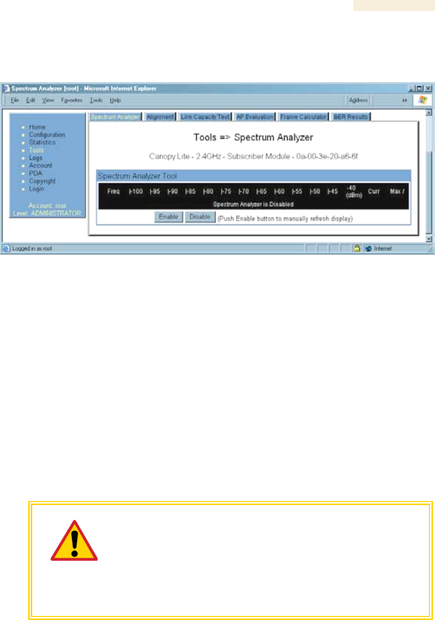
Release 8 Operations Guide
Issue 2, November 2007 Draft 5 for Regulatory Review 364
21.1.2 Graphical Spectrum Analyzer Display (Not available for Canopy OFDM)
An SM/BHS displays the graphical spectrum analyzer. An example of the Spectrum
Analyzer tab is shown in Figure 137.
Figure 137: Spectrum Analyzer tab of SM, example
Colors in the display have the following meanings:
◦ Green bars show the most recent measurements.
◦ Yellow ticks show the maximum measurements from the current spectrum
analysis session.
◦ Red ticks show measurements of −40 dBm or stronger.
To keep the displayed data current, either set “Auto Refresh” on the module’s
Configuration => General page to a few seconds, or repeatedly click the Enable button.
When you are finished analyzing the spectrum, click the Disable button to return the
module to normal operation.
21.1.3 Using the AP as a Spectrum Analyzer (Not available for Canopy OFDM)
You can temporarily change an AP into an SM and thereby use the spectrum analyzer
functionality. This is the only purpose supported for the transformation.
CAUTION!
When you change an AP into an SM, any connections to SMs off that AP are
lost. Therefore, you should ensure you are connected to the AP through its
Ethernet side (not RF side) before changing it into an SM.
For example, if you are connected to an AP through one of its SMs and
mistakenly change the AP into an SM, you will lose connectivity and will need
to gain access to the Ethernet side of the AP through another part of your
network to change it back into an AP.

Release 8 Operations Guide
Issue 2, November 2007 Draft 5 for Regulatory Review 365
To transform the AP into an SM for spectrum analysis and then return the device to
an AP, perform the following steps.
Procedure 34: Using the Spectrum Analyzer in AP feature
1. Connect to the wired Ethernet interface of the AP.
2. Access the General tab of the Configuration page in the AP.
3. Set the Device Setting parameter to SM.
4. Click the Save Changes button.
5. Click the Reboot button.
6. When the module has rebooted as an SM, click the Tools navigation link on the
left side of the Home page.
7. Click the Spectrum Analyzer tab.
8. Either set this page to automatically refresh or repeatedly click the Enable
button.
RESULT: The SM enters the scan mode.
9. When you are finished analyzing the spectrum, click the Disable button.
10. In the left-side navigation links, click Configuration.
11. Click the General tab.
12. Set the Device Setting parameter to AP.
13. Click the Save Changes button.
14. Click the Reboot button.
RESULT: The AP boots with its previous frequency setting.
=========================== end of procedure ===========================
21.2 CONSIDERING SOFTWARE RELEASE COMPATIBILITY
Within the same Canopy network, modules can operate on multiple software releases.
However, the features that can be enabled are limited to those that the earliest software
supports.
21.2.1 Designations for Hardware in Radios
Canopy documentation refers to hardware series (for example, Series P9). Canopy
Release 8 requires APs, BHs, and AES SMs to be Series P9 or later hardware.
The correlation between hardware series and the MAC addresses of the radio modules
is provided in Table 52.
Table 52: Hardware series by MAC address
Hardware Series
Radio
Frequency
Band
Range
P7 or P8
in These MAC
Addresses
P9 or Later
in These MAC
Addresses
900
None
All
2.4
≤ 0A003E20672B
≥ 0A003E20672C
5.2
≤ 0A003E00F4E3
≥ 0A003E00F4E4
5.4
None
All
5.7
≤ 0A003EF12AFE
≥ 0A003EF12AFF

Release 8 Operations Guide
Issue 2, November 2007 Draft 5 for Regulatory Review 366
Differences in capabilities among these hardware series are summarized in Table 53.
Table 53: Hardware series differences
Availability per
Hardware Series
Capability
P7
P8
P9
Auto-sense Ethernet cable scheme
no
yes
yes
Support CMMmicro
no
yes
yes
Support hardware scheduling in APs1
no
no
yes
Support 2X operation in APs and SMs
no
no
yes
NOTES:
1. An SM of P7 or P8 series requires an FPGA load through
CNUT for access to hardware scheduling, and then only
at 1X operation. An AP of P7 or P8 series cannot perform
hardware scheduling.
Advantage Series P9 APs provide higher throughput and lower latency than earlier series
Advantage APs and support configuring the high-priority channel per SM. Regular
Canopy Series P9 APs do not provide the higher throughput and lower latency, but they
do support configuring the high-priority channel per SM.
21.2.2 CMMmicro Software and Hardware Compatibility
The CMMmicro contains both a programmable logic device (PLD) and software. These
must be compatible. For example, the PLD that is compatible with CMMmicro Release
2.0.8 is PLD 5. Further, the CMMmicro must be compatible with both the application
software release and the hardware of attached APs and BHs. These attached modules
must have been manufactured in October 2002 or later.
APs and BHs that were manufactured earlier do not support sync on the power leads of
the Ethernet port. To determine whether the AP or BH hardware is compatible with the
CMMmicro, see Table 54.
Table 54: AP/BH compatibility with CMMmicro
Range of MAC Addresses (ESNs)
Frequency
Band
Range
Incompatible
with CMMmicro
Compatible
with CMMmicro
900 MHz AP
none
all
2.4 GHz
none
all
5.2 GHz
≤ 0A003E0021C8
≥ 0A003E0021C9
5.4 GHz
none
all
5.7 GHz
≤ 0A003EF00F79
≥ 0A003EF00F7A

Release 8 Operations Guide
Issue 2, November 2007 Draft 5 for Regulatory Review 367
21.2.3 MIB File Set Compatibility
Although MIB files are text files (not software), they define objects associated with
configurable parameters and indicators for the module and its links. In each release,
some of these parameters and indicators are not carried forward from the previous
release, and some parameters and indicators are introduced or changed.
For this reason, use the MIB files from your download to replace previous MIB files in
conjunction with your software upgrades, even if the file names are identical to those of
your previous files. Date stamps on the MIB files distinguish the later set.
21.3 REDEPLOYING MODULES
Successfully redeploying a module may involve
◦ maintaining full and accurate records of modules being redeployed from
warehouse stock.
◦ exercising caution about
− software compatibility. For example, whether desired features can be
enabled with the redeployed module in the network.
− procedural handling of the module. For example
◦ whether to align the SM or BHS by power level and jitter or by only jitter.
◦ whether the module auto-senses the Ethernet cable connector scheme.
− hardware compatibility. For example, where a CMMmicro is deployed.
− the value of each configurable parameter. Whether all are compatible in the
new destination.
◦ remembering to use auto discovery to add the redeployed SM to the network
in Prizm.
21.3.1 Wiring to Extend Network Sync
The following procedure can be used to extend network sync by one additional hop, as
described under Passing Sync in an Additional Hop on Page 95. Where a collocated
module receives sync over the air, the collocated modules can be wired to pass the sync
as follows:
Procedure 35: Extending network sync
1. Connect the GPS Utility ports of the collocated modules using a sync cable with
RJ-11 connectors.
2. Set the Sync Input parameter on the Configuration page of the collocated AP or
BH timing master to Sync to Received Signal (Timing Port).
3. Set the Frame Timing Pulse Gated parameter on the Configuration page of the
collocated SM or BH timing slave to Enable.
NOTE: This setting prevents interference in the event that the SM or BH timing
slave loses sync.
=========================== end of procedure ===========================

Release 8 Operations Guide
Issue 2, November 2007 Draft 5 for Regulatory Review 369
22 SECURING YOUR NETWORK
22.1 ISOLATING APS FROM THE INTERNET
Ensure that the IP addresses of the APs in your network
◦ are not routable over the Internet.
◦ do not share the subnet of the IP address of your user.
RFC 1918, Address Allocation for Private Subnets, reserves for private IP networks three
blocks of IP addresses that are not routable over the Internet:
◦ /8 subnets have one reserved network, 10.0.0.0 to 10.255.255.255.
◦ /16 subnets have 16 reserved networks, 172.16.0.0 to 172.31.255.255.
◦ /24 subnets have 256 reserved networks, 192.168.0.0 to 192.168.255.255.
22.2 ENCRYPTING CANOPY RADIO TRANSMISSIONS
Canopy systems employ the following forms of encryption for security of the wireless link:
◦ BRAID–a security scheme that the cellular industry uses to authenticate wireless
devices.
◦ DES–Data Encryption Standard, an over-the-air link option that uses secret
56-bit keys and 8 parity bits.
◦ AES–Advanced Encryption Standard, an extra-cost over-the-air link option that
provides extremely secure wireless connections. AES uses 128-bit secret keys
as directed by the government of the U.S.A. AES is not exportable and requires
a special AP to process the large keys.
BRAID is a stream cipher that the TIA (Telecommunications Industry Association) has
standardized. Standard Canopy APs and SMs use BRAID encryption to
◦ calculate the per-session encryption key (independently) on each end of a link.
◦ provide the digital signature for authentication challenges.
22.2.1 DES Encryption
Standard Canopy modules provide DES encryption. DES performs a series of bit
permutations, substitutions, and recombination operations on blocks of data.
DES Encryption does not affect the performance or throughput of the system.
22.2.2 AES Encryption
Motorola also offers Canopy products that provide AES encryption. AES uses the
Rijndael algorithm and 128-bit keys to establish a higher level of security than DES.
Because of this higher level of security, the government of the U.S.A. controls the export
of communications products that use AES (among which the Canopy AES feature
activation key is one) to ensure that these products are available in only certain regions
and by special permit.

Release 8 Operations Guide
Issue 2, November 2007 Draft 5 for Regulatory Review 370
The Canopy distributor or reseller can advise service providers about current regional
availability. Canopy AES products are certified as compliant with the Federal Information
Processing Standards (FIPS) in the U.S.A. The National Institute of Standards and
Technology (NIST) in the U.S.A. has specified AES for significantly greater security than
that which DES provides. NIST selected the AES algorithm for providing the best
combination of security, performance, efficiency, implementation, and flexibility. NIST
collaborates with industry to develop and apply technology, measurements, and
standards.
22.2.3 AES-DES Operability Comparisons
This section describes the similarities and differences between DES and AES products,
and the extent to which they may interoperate.
The DES AP and the DES BHM modules are factory-programmed to enable or disable
DES encryption. Similarly, the AES AP and the AES BHM modules are factory-
programmed to enable or disable AES encryption. In either case, the authentication key
entered in the Configuration page establishes the encryption key. For this reason,
the authentication key must be the same on each end of the link. See Authentication Key
on Page 283.
Feature Availability
Canopy AES products run the same software as DES products. Thus feature availability
and functionality are and will continue to be the same, regardless of whether AES
encryption is enabled. All interface screens are identical. However, when encryption
is enabled on the Configuration screen
◦ the AES product provides AES encryption.
◦ the DES product provides DES encryption.
Canopy AES products and DES products use different FPGA (field-programmable gate
array) loads. However, the AES FPGA will be upgraded as needed to provide new
features or services similar to those available for DES products.
Canopy DES products cannot be upgraded to AES. To have the option of AES
encryption, the operator must purchase AES products.
Interoperability
Canopy AES products and DES products do not interoperate when enabled for
encryption. For example, An AES AP with encryption enabled cannot communicate with
DES SMs. Similarly, an AES Backhaul timing master module with encryption enabled
cannot communicate with a DES Backhaul timing slave module.
However, if encryption is disabled, AES modules can communicate with DES modules.

Release 8 Operations Guide
Issue 2, November 2007 Draft 5 for Regulatory Review 371
22.3 MANAGING MODULE ACCESS BY PASSWORDS
22.3.1 Adding a User for Access to a Module
From the factory, each Canopy module has a preconfigured administrator-level account
in the name root, which initially requires no associated password. This is the same
root account that you may have used for access to the module by telnet or ftp.
If you upgrade a module to Release 8
◦ an account is created in the name admin.
◦ both admin and root inherit the password that was previously used for access
to the module:
− the Full Access password, if one was set.
− the Display-Only Access password, if one was set and no Full Access
password was set.
IMPORTANT!
If you use Prizm, do not delete the root account from any module. If you use an
NMS that communicates with modules through SNMP, do not delete the root
account from any module unless you first can confirm that the NMS does not rely
on the root account for access to the modules.
Each module supports four or fewer user accounts, regardless of account levels. The
available levels are
◦ ADMINISTRATOR, who has full read and write permissions. This is the level of
the root and admin users, as well as any other administrator accounts that one
of them creates.
◦ INSTALLER, who has permissions identical to those of ADMINISTRATOR
except that the installer cannot add or delete users or change the password of
any other user.
◦ GUEST, who has no write permissions and only a limited view of General Status
tab, as shown in Figure 138, and can log in as a user.
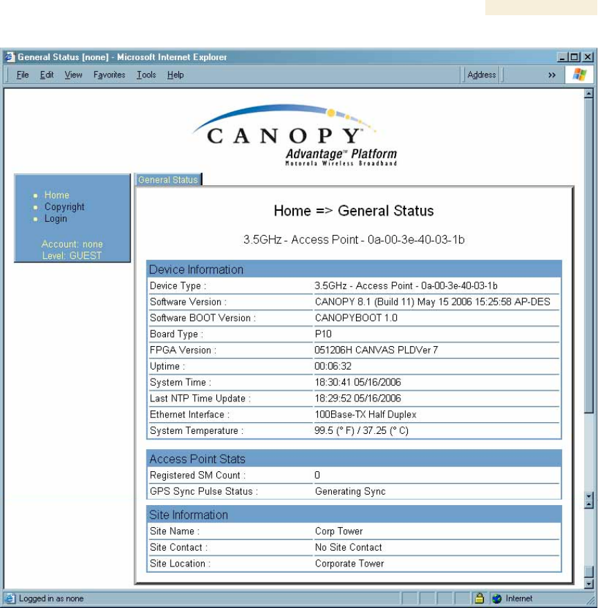
Release 8 Operations Guide
Issue 2, November 2007 Draft 5 for Regulatory Review 372
Figure 138: General Status tab view for GUEST-level account
An example of the Add User tab is displayed in Figure 139.
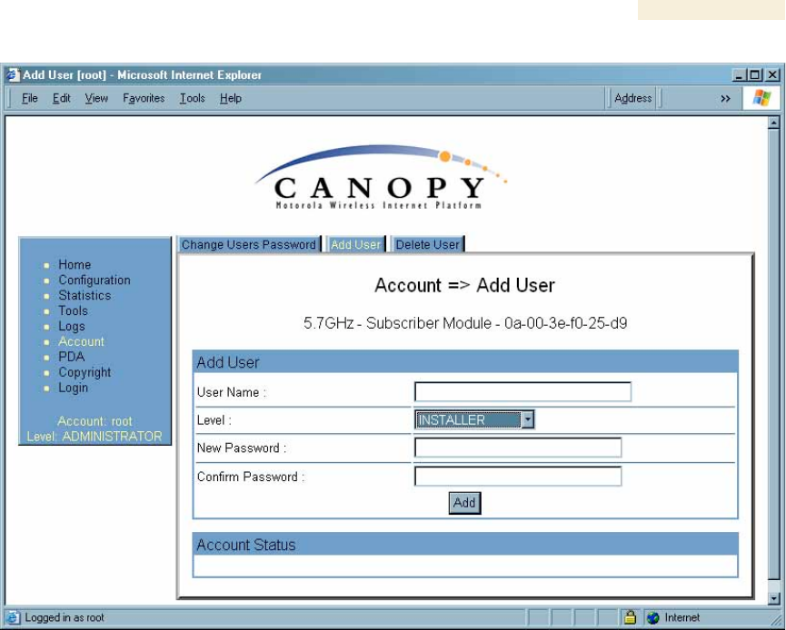
Release 8 Operations Guide
Issue 2, November 2007 Draft 5 for Regulatory Review 373
Figure 139: Add User tab of SM, example
After a password has been set for any ADMINISTRATOR-level account, initial access to
the module GUI opens the view of GUEST level (Figure 138).
Accounts that cannot be deleted are
◦ the current user's own account.
◦ the last remaining account of ADMINISTRATOR level.
22.3.2 Overriding Forgotten IP Addresses or Passwords on AP, SM, or BH
Canopy systems offer a plug that allows you to temporarily override some AP/SM/BH
settings and thereby regain control of the module. This plug is needed for access to the
module in any of the following cases:
◦ You have forgotten either
− the IP address assigned to the module.
− the password that provides access to the module.
◦ The module has been locked by the No Remote Access feature. (See Denying
All Remote Access on Page 451 and Reinstating Remote Access Capability on
Page 451.)
◦ You want local access to a module that has had the 802.3 link disabled in the
Configuration page.
You can configure the module such that, when it senses the override plug, it responds by
either
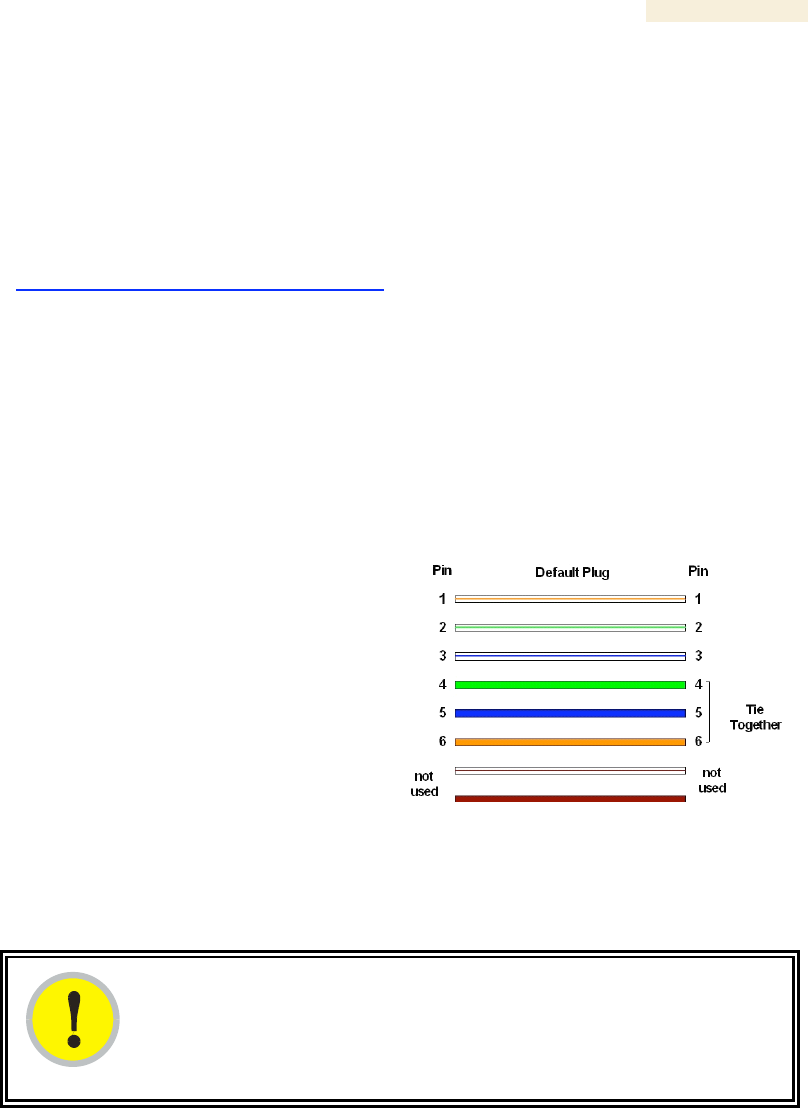
Release 8 Operations Guide
Issue 2, November 2007 Draft 5 for Regulatory Review 374
◦ resetting the LAN1 IP address to 169.254.1.1, allowing access through the
default configuration without changing the configuration, whereupon you will be
able to view and reset any non-default values as you wish.
◦ resetting all configurable parameters to their factory default values.
Acquiring the Override Plug
You can either purchase or fabricate an override plug as follows. To purchase an
override plug for a nominal fee, order the plug at
http://www.best-tronics.com/motorola.htm. To fabricate an override plug, perform the
following steps.
Procedure 36: Fabricating an override plug
1. Install an RJ-11 6-pin connector onto a 6-inch length of CAT 5 cable.
2. Pin out all 6-pins.
3. Short (solder together) Pins 4 and 6 on the other end. Do not connect any other
wires to anything. The result should be as shown in Figure 140.
=========================== end of procedure ===========================
Pin 1 → white / orange ← Pin 1
Pin 2 → white / green ← Pin 2
Pin 3 → white / blue ← Pin 3
Pin 4 → green ← Pin 6
Pin 5 → blue ← Pin 5
Pin 6 → orange ← Pin 4
Figure 140: RJ-11 pinout for the override plug
Using the Override Plug
IMPORTANT!
While the override plug is connected to a module, the module can neither
register nor allow registration of another module.
To regain access to the module, perform the following steps.
Procedure 37: Regaining access to a module
1. Insert the override plug into the RJ-11 GPS utility port of the module.
2. Power cycle by removing, then re-inserting, the Ethernet cable.
RESULT: The module boots with the default IP address of 169.254.1.1, password
fields blank, and all other configuration values as previously set.
3. Wait approximately 30 seconds for the boot to complete.
Release 8 Operations Guide
Issue 2, November 2007 Draft 5 for Regulatory Review 375
4. Remove the override plug.
5. Set passwords and IP address as desired.
6. Change configuration values if desired.
7. Click the Save Changes button.
8. Click the Reboot button.
=========================== end of procedure ===========================
22.3.3 Overriding Forgotten IP Addresses or Passwords on CMMmicro
By using an override toggle switch on the CMMmicro circuit board, you can temporarily
override a lost or unknown IP address or password as follows:
◦ Up is the override position in which a power cycle causes the CMMmicro to boot
with the default IP address (169.254.1.1) and no password required.
◦ Down is the normal position in which a power cycle causes the CMMmicro to
boot with your operator-set IP address and password(s).
To override a lost or unknown IP address or password, perform the following steps.
Procedure 38: Using the override switch to regain access to CMMmicro
IMPORTANT!
In override mode
◦ a CMMmicro provides no power on its ports.
◦ any APs or BHs connected to the CMMmicro are not powered.
◦ you cannot gain browser access to the CMMmicro through any
connected APs or BHs.
1. Gain physical access to the inside of the CMMmicro enclosure.
2. Establish direct Ethernet connectivity to the CMMmicro (not through an AP or
BH).
3. Flip the toggle switch up (toward you).
4. Power cycle the CMMmicro.
RESULT: The module reboots with the default IP address of 169.254.1.1,
password fields blank, and all other configuration values as previously set.
5. Set passwords as desired, or enter a blank space to set no password.
6. Change configuration values if desired.
7. Click the Save Changes button.
8. Flip the toggle switch down (away from you).
9. Click the Reboot button.
=========================== end of procedure ===========================
22.4 REQUIRING SM AUTHENTICATION
Through the use of Prizm Release 2.0 or later, or BAM Release 2.1, you can enhance
network security by requiring SMs to authenticate when they register. Three keys and a
random number are involved in authentication as follows:

Release 8 Operations Guide
Issue 2, November 2007 Draft 5 for Regulatory Review 376
◦ factory-set key in each SM. Neither the subscriber nor the network operator can
view or change this key.
◦ authentication key, also known as authorization key and skey. This key matches
in the SM and AP as the Authentication Key parameter, and in the Prizm
database.
◦ random number, generated by Prizm or BAM and used in each attempt by an SM
to register and authenticate. The network operator can view this number.
◦ session key, calculated separately by the SM and Prizm or BAM, based on both
the authentication key (or, by default, the factory-set key) and the random
number. Prizm or BAM sends the session key to the AP. The network operator
cannot view this key.
None of the above keys is ever sent in an over-the-air link during an SM registration
attempt. However, with the assumed security risk, the operator can create and configure
the Authentication Key parameter. See Authentication Key on Page 283.
22.5 FILTERING PROTOCOLS AND PORTS
You can filter (block) specified protocols and ports from leaving the SM and entering the
Canopy network. This protects the network from both intended and inadvertent packet
loading or probing by network users. By keeping the specified protocols or ports off the
network, this feature also provides a level of protection to users from each other.
Protocol and port filtering is set per SM. Except for filtering of SNMP ports, filtering occurs
as packets leave the SM. If an SM is configured to filter SNMP, then SNMP packets are
blocked from entering the SM and, thereby, from interacting with the SNMP portion of the
protocol stack on the SM.
22.5.1 Port Filtering with NAT Enabled
Where NAT is enabled, you can filter only the three user-defined ports. The following are
example situations in which you can configure port filtering where NAT is enabled.
◦ To block a subscriber from using FTP, you can filter Ports 20 and 21 (the FTP
ports) for both the TCP and UDP protocols.
◦ To block a subscriber from access to SNMP, you can filter Ports 161 and 162
(the SNMP ports) for both the TCP and UDP protocols.
NOTE: In only the SNMP case, filtering occurs before the packet interacts with
the protocol stack.
22.5.2 Protocol and Port Filtering with NAT Disabled
Where NAT is disabled, you can filter both protocols and the three user-defined ports.
Using the check boxes on the interface, you can either
◦ allow all protocols except those that you wish to block.
◦ block all protocols except those that you wish to allow.
You can allow or block any of the following protocols:
◦ PPPoE (Point to Point Protocol over Ethernet)
◦ Any or all of the following IPv4 (Internet Protocol version 4) protocols:
− SMB (Network Neighborhood)
− SNMP

Release 8 Operations Guide
Issue 2, November 2007 Draft 5 for Regulatory Review 377
− Up to 3 user-defined ports
− All other IPv4 traffic (see Figure 141)
◦ Uplink Broadcast
◦ ARP (Address Resolution Protocol)
◦ All others (see Figure 141)
PPPoE ARP
All Other IPv4
User
Defined
Port 1
IPv4
Multicast
BootP
Server
BootP
Client
SNMP
SMB
User
Defined
Port 3
User
Defined
Port 2
All Others
Figure 141: Categorical protocol filtering
The following are example situations in which you can configure protocol filtering where
NAT is disabled:
◦ If you block a subscriber from only PPoE and SNMP, then the subscriber retains
access to all other protocols and all ports.
◦ If you block PPoE, IPv4, and Uplink Broadcast, and you also check the
All others selection, then only Address Resolution Protocol is not filtered.
The ports that are filtered as a result of protocol selections in the Protocol Filtering tab of
the SM are listed in Table 55. Further information is provided under Protocol Filtering Tab
of the SM on Page 289.

Release 8 Operations Guide
Issue 2, November 2007 Draft 5 for Regulatory Review 378
Table 55: Ports filtered per protocol selections
Protocol
Selected
Port Filtered (Blocked)
SMB
Destination Ports 137 TCP and UDP,
138 UDP, 139 TCP, 445 TCP
SNMP
Destination Ports 161 TCP and UDP,
162 TCP and UDP
Bootp Client
Source Port 68 UDP
Bootp Server
Source Port 67 UDP
22.6 ENCRYPTING DOWNLINK BROADCASTS
An AP can be enabled to encrypt downlink broadcast packets such as the following:
◦ ARP
◦ NetBIOS
◦ broadcast packets containing video data on UDP.
The encryption used is DES for a DES module, and AES for an AES module. Before the
Encrypt Downlink Broadcast feature is enabled on the AP, air link security should be
enabled on the AP.
22.7 ISOLATING SMs
In the Release 8 or later AP, you can prevent SMs in the sector from directly
communicating with each other. In CMMmicro Release 2.2 or later, you can prevent
connected APs from directly communicating with each other, which prevents SMs that
are in different sectors of a cluster from communicating with each other.
In the AP, the SM Isolation parameter is available in the General tab of the Configuration
web page. In the drop-down menu for that parameter, you can configure the SM Isolation
feature by any of the following selections:
◦ Disable SM Isolation (the default selection). This allows full communication
between SMs.
◦ Block SM Packets from being forwarded. This prevents both
multicast/broadcast and unicast SM-to-SM communication.
◦ Block and Forward SM Packets to Backbone. This not only prevents
multicast/broadcast and unicast SM-to-SM communication but also sends the
packets, which otherwise would have been handled SM to SM, through the
Ethernet port of the AP.
In the CMMmicro, SM isolation treatment is the result of how you choose to manage the
port-based VLAN feature of the embedded switch, where you can switch all traffic from
any AP or BH to an uplink port that you specify. However, this is not packet level
switching. It is not based on VLAN IDs. See the VLAN Port Configuration parameter in
Figure 72: Configuration page of CMMmicro, example on Page 224.

Release 8 Operations Guide
Issue 2, November 2007 Draft 5 for Regulatory Review 379
22.8 FILTERING MANAGEMENT THROUGH ETHERNET
You can configure the SM to disallow any device that is connected to its Ethernet port
from accessing the IP address of the SM. If you set the Ethernet Access Control
parameter to Enabled, then
◦ no attempt to access the SM management interface (by http, SNMP, telnet, ftp,
or tftp) through Ethernet can succeed.
◦ any attempt to access the SM management interface over the air (by IP address,
presuming that LAN1 Network Interface Configuration, Network Accessibility
is set to Public, or by link from the Session Status or Remote Subscribers tab in
the AP) is unaffected.
22.9 ALLOWING MANAGEMENT FROM ONLY SPECIFIED IP
ADDRESSES
The Security tab of the Configuration web page in the AP, SM, and BH includes the IP
Access Control parameter. You can specify one, two, or three IP addresses that should
be allowed to access the management interface (by http, SNMP, telnet, ftp, or tftp).
If you select
◦ IP Access Filtering Disabled, then management access is allowed from any IP
address, even if the Allowed Source IP 1 to 3 parameters are populated.
◦ IP Access Filtering Enabled, and specify at least one address in the Allowed
Source IP 1 to 3 parameter, then management access is limited to the specified
address(es). If you intend to use Prizm to manage the element, then you must
ensure that the IP address of the Prizm server is listed here.
22.10 CONFIGURING MANAGEMENT IP BY DHCP
The IP tab in the Configuration web page of every Canopy radio contains a
LAN1 Network Interface Configuration, DHCP State parameter that, if enabled,
causes the IP configuration (IP address, subnet mask, and gateway IP address) to be
obtained through DHCP instead of the values of those individual parameters. The setting
of this DHCP state parameter is also viewable, but not settable, in the Network Interface
tab of the Home page.
In the SM, this parameter is settable
◦ in the NAT tab of the Configuration web page, but only if NAT is enabled.
◦ in the IP tab of the Configuration web page, but only if the
Network Accessibility parameter in the IP tab is set to Public.

Release 8 Operations Guide
Issue 2, November 2007 Draft 5 for Regulatory Review 381
23 MANAGING BANDWIDTH AND
AUTHENTICATION
This section provides a high-level description of bandwidth and authentication
management in a Canopy network. For more specific information, see Canopy Bandwidth
and Authentication Manager (BAM) User Guide or the Motorola Canopy Prizm User
Guide.
23.1 MANAGING BANDWIDTH WITHOUT BAM
Unless Prizm or BAM is deployed and is configured in the AP, bandwidth management is
limited to applying a single sustained data rate value (for uplink and for downlink) and a
single burst allocation value (for uplink and for downlink) to every SM that registers in
the AP.
23.2 BANDWIDTH AND AUTHENTICATION MANAGER (BAM)
SERVICES AND FEATURES
Prizm or BAM enables you to perform the following management operations on SMs:
◦ Change the key that the SMs need for authenticating.
◦ Temporarily suspend or reinstate a subscriber.
◦ Set burst size and data transfer rate caps for an SM or group of SMs.
◦ Use licensing to uncap an SM or group of SMs.
◦ List all ESNs that are associated with a specified VLAN ID.
◦ Associate or dissociate an SM or group of SMs with a specified VLAN ID.
◦ Set VLAN parameters.
◦ Toggle whether to send those VLAN parameters to the SMs.
◦ Set CIR parameters for low-priority and high-priority channel rates.
◦ Toggle whether to send those CIR parameters to the SMs.
◦ Toggle whether to enable the high-priority channel in the SMs.
23.2.1 Bandwidth Manager Capability
Prizm or BAM allows you to set bandwidth per SM for sustained rates and burst rates.
With this capability, the Canopy system allows both
◦ burst rates beyond those of many other broadband access solutions.
◦ control of average bandwidth allocation to prevent excessive bandwidth usage by
a subscriber.
All packet throttling occurs in the SMs and APs based on Quality of Service (QoS) data
that the Prizm or BAM server provides. No server processing power or network
messages are needed for packet throttling.
QoS management also supports marketing of broadband connections at various data
rates, for operator-defined groups of subscribers, and at various price points. This allows
you to meet customer needs at a price that the customer deems reasonable and
affordable.
When BAM is enabled in the AP Configuration page, bandwidth management is
expanded to apply uniquely specified sustained data rate and burst allocation values to
each registered SM. Thus, you can define differently priced tiers of subscriber service.
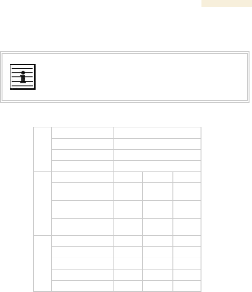
Release 8 Operations Guide
Issue 2, November 2007 Draft 5 for Regulatory Review 382
Designing Tiered Subscriber Service Levels
Examples of levels of service that vary by bandwidth capability are provided in Table 56
and Table 57.
NOTE:
The speeds that these tables correlate to service levels are comparative
examples. Actual download times may be greater due to use of the bandwidth
by other SMs, congestion on the local network, congestion on the Internet,
capacity of the serving computer, or other network limitations.
Table 56: Example times to download for typical tiers of service with Canopy AP
AP
Canopy
SM
Canopy
Operation
1X
Equipment
Max burst speed
4.4 Mbps
Service Type
Premium
Regular
Basic
Sustained Downlink
Data Rate
5250
Kbps
1000
Kbps
256
Kbps
Sustained Uplink
Data Rate
1750
Kbps
500
Kbps
128
Kbps
Example Settings
Downlink and Uplink
Burst Allocations
500000
Kb
80000
Kb
40000
Kb
Web page
<1
<1
<1
5 MB
9
9
9
20 MB
36
80
470
50 MB
91
320
1400
Download (sec)
300 MB
545
2320
9220

Release 8 Operations Guide
Issue 2, November 2007 Draft 5 for Regulatory Review 383
Table 57: Example times to download for typical tiers of service with Advantage AP
AP
Advantage
Advantage
SM
Canopy
Advantage
Operation
1X
2X
2X
Equipment
Max burst speed
5 Mbps
10 Mbps
10 Mbps
Service Type
Premium
Regular
Basic
Premium
Regular
Basic
Premium
Sustained
Downlink
Data Rate
5250
Kbps
1000
Kbps
256
Kbps
5250
Kbps
1000
Kbps
256
Kbps
2000
Kbps
Sustained Uplink
Data Rate
1750
Kbps
500
Kbps
128
Kbps
1750
Kbps
500
Kbps
128
Kbps
20000
Kbps
Example Settings
Downlink and
Uplink
Burst
Allocations
500000
Kb
80000
Kb
40000
Kb
500000
Kb
80000
Kb
40000
Kb
500000
Kb
Web page
<1
<1
<1
<1
<1
<1
<1
5 MB
8
8
8
4
4
4
4
20 MB
32
80
470
16
80
470
16
50 MB
80
320
1400
40
320
1400
40
Download (sec)
300 MB
480
2320
9220
362
2320
9220
240
23.2.2 Authentication Manager Capability
Prizm or BAM allows you to set per AP a requirement that each SM registering to the AP
must authenticate. When AP Authentication Server (APAS) is enabled in the AP, any SM
that attempts to register to the AP is denied service if authentication fails, such as (but
not limited to) when no Prizm or BAM server is operating or when the SM is not listed in
the database.
If a Prizm or BAM server drops out of service where no redundant server exists
◦ an SM that attempts to register is denied service.
◦ an SM that is already in session remains in session
In a typical Canopy network, some SMs re-register daily (when subscribers power down
the SMs, for example), and others do not re-register in a period of several weeks.
Whenever an authentication attempt fails, the SM locks out of any other attempt to
register itself to the same AP for the next 15 minutes.

Release 8 Operations Guide
Issue 2, November 2007 Draft 5 for Regulatory Review 385
24 MANAGING THE NETWORK FROM A
MANAGEMENT STATION (NMS)
SNMPv2 (Simple Network Management Protocol Version 2) can be used to manage and
monitor the Canopy modules under SMI (Structure of Management Information)
specifications. SMI specifies management information definitions in ASN.1 (Abstract
Syntax Notation One) language. SNMPv2 supports both 32-bit and 64-bit counters. The
SMI for SNMPv2 is defined in RFC 1902 at http://www.faqs.org/rfcs/rfc1902.html.
24.1 ROLES OF HARDWARE AND SOFTWARE ELEMENTS
24.1.1 Role of the Agent
In SNMP, software on each managed device acts as the agent. The agent collects and
stores management information in ASN.1 format, in a structure that a MIB (management
information base) defines. The agent responds to commands to
◦ send information about the managed device.
◦ modify specific data on the managed device.
24.1.2 Role of the Managed Device
In SNMP, the managed device is the network element that operates on the agent
software. In the Canopy network, this managed device is the module (AP, SM, or BH).
With the agent software, the managed device has the role of server in the context of
network management.
24.1.3 Role of the NMS
In SNMP, the NMS (network management station) has the role of client. An application
(manager software) operates on the NMS to manage and monitor the modules in the
network through interface with the agents.
24.1.4 Dual Roles for the NMS
The NMS can simultaneously act as an agent. In such an implementation, the NMS acts
as
◦ client to the agents in the modules, when polling for the agents for information
and sending modification data to the agents.
◦ server to another NMS, when being polled for information gathered from the
agents and receiving modification data to send to the agents.
24.1.5 Simple Network Management Protocol (SNMP) Commands
To manage a module, SNMPv2 supports the set command, which instructs the agent to
change the data that manages the module.

Release 8 Operations Guide
Issue 2, November 2007 Draft 5 for Regulatory Review 386
To monitor a network element (Canopy module), SNMPv2 supports
◦ the get command, which instructs the agent to send information about the
module to the manager in the NMS.
◦ traversal operations, which the manager uses to identify supported objects and to
format information about those objects into relational tables.
In a typical Canopy network, the manager issues these commands to the agents of more
than one module (to all SMs in the operator network, for example).
24.1.6 Traps from the Agent
When a specified event occurs in the module, the agent initiates a trap, for which the
agent sends an unsolicited asynchronous message to the manager.
24.1.7 AP SNMP Proxy to SMs
When the AP receives from Prizm or an NMS an SNMP request for an SM, it is capable
of sending that request via proxy to the SM. In this case, the SM responds directly to
Prizm or the NMS. (The AP performs no processing on the response.)
24.2 MANAGEMENT INFORMATION BASE (MIB)
The MIB, the SNMP-defined data structure, is a tree of standard branches that lead to
optional,
non-standard positions in the data hierarchy. The MIB contains both
◦ objects that SNMP is allowed to control (bandwidth allocation or access, for
example)
◦ objects that SNMP is allowed to monitor (packet transfer, bit rate, and error data,
for example).
The path to each object in the MIB is unique to the object. The endpoint of the path is the
object identifier.
24.2.1 Cascading Path to the MIB
The standard MIB hierarchy includes the following cascading branch structures:
◦ the top (standard body) level:
− ccitt (0)
− iso (1)
− iso-ccitt (2)
◦ under iso (1) above:
− standard (0)
− registration-authority (1)
− member-body (2)
− identified-organization (3)
◦ under identified-organization (3) above:
− dod (6)
− other branches
◦ under dod (6) above:

Release 8 Operations Guide
Issue 2, November 2007 Draft 5 for Regulatory Review 387
− internet (1)
− other branches
◦ under internet (1) above:
− mgmt (2)
− private (4)
− other branches
◦ under mgmt (2) above: mib-2 (1) and other branches. (See MIB-II below.)
under private (4) above: enterprise (1) and other branches. (See Canopy
Enterprise MIB below.)
Beneath this level are non-standard branches that the enterprise may define.
Thus, the path to an object that is managed under MIB-II begins with the decimal string
1.3.6.1.2.1 and ends with the object identifier and instance(s), and the path to an object
that is managed under the Canopy Enterprise MIB begins with 1.3.6.1.4.1, and ends with
the object identifier and instance(s).
24.2.2 Object Instances
An object in the MIB can have either only a single instance or multiple instances, as
follows:
◦ a scalar object has only a single instance. A reference to this instance is
designated by .0, following the object identifier.
◦ a tabular object has multiple instances that are related to each other. Tables in
the MIB associate these instances. References to these instances typically are
designated by .1, .2, and so forth, following the object identifier.
24.2.3 Management Information Base Systems and Interface (MIB-II)
The standard MIB-II (Management Information Base systems and interface) objects are
programmed into the Canopy modules. To read this MIB, see Management Information
Base for Network Management of TCP/IP-based Internets: MIB II, RFC 1213 at
http://www.faqs.org/rfcs/rfc1213.html.
The MIB-II standard categorizes each object as one of the types defined in Table 58.
Table 58: Categories of MIB-II objects
Objects in
category…
Control or identify the status of…
system
system operations in the module.
interfaces
the network interfaces for which the module is configured.
ip
Internet Protocol information in the module.
icmp
Internet Control Message Protocol information in the module.
(These messages flag IP problems and allow IP links to be tested.)
tcp
Transport Control Protocol information in the module (to control
and ensure the flow of data on the Internet).
udp
User Datagram Protocol information in the module (for checksum
and address).

Release 8 Operations Guide
Issue 2, November 2007 Draft 5 for Regulatory Review 388
24.2.4 Canopy Enterprise MIB
The Canopy Enterprise MIB provides additional reporting and control, extending the
objects for any NMS that uses SNMP interaction. This MIB comprises five text files that
are formatted in standard ASN.1 (Abstract Syntax Notation One) language.
To use this MIB, perform the following steps.
Procedure 39: Installing the Canopy Enterprise MIB files
1. On the NMS, immediately beneath the root directory, create directory
mibviewer.
2. Immediately beneath the mibviewer directory, create directory canopymibs.
3. Download the following three standard MIB files from the Internet Engineering
Task Force at http://www.simpleweb.org/ietf/mibs into the
mibviewer/canopymibs directory on the NMS:
◦ SNMPv2-SMI.txt, which defines the Structure of Management Information
specifications.
◦ SNMPv2-CONF.txt, which allows macros to be defined for object group,
notification group, module compliance, and agent capabilities.
◦ SNMPv2-TC.txt, which defines general textual conventions.
4. Move the following five files from your Canopy software package directory into
the mibviewer/canopymibs directory on the NMS (if necessary, first
download the software package from http://www.motorola.com/canopy):
◦ whisp-tcv2-mib.txt (Textual Conventions MIB), which defines Canopy
system-specific textual conventions
◦ WHISP-GLOBAL-REG-MIB.txt (Registrations MIB), which defines
registrations for global items such as product identities and product
components.
◦ WHISP-BOX-MIBV2-MIB.txt (Box MIB), which defines module-level (AP,
SM, and BH) objects.
◦ WHISP-APS-MIB.txt (APs MIB), which defines objects that are specific to
the AP or BH timing master.
◦ WHISP-SM-MIB.txt (SM MIB), which defines objects that are specific to
the SM or BH timing slave.
◦ CMM3-MIB.txt (CMM3 MIB), which defines objects that are specific to the
CMMmicro.
IMPORTANT!
Do not edit these MIB files in ASN.1. These files are intended for manipulation
by only the NMS. However, you can view these files through a commercially
available MIB viewer. Such viewers are listed under MIB Viewers on Page 405.
5. Download a selected MIB viewer into directory mibviewer.
6. As instructed by the user documentation that supports your NMS, import the
eight MIB files that are listed above.
=========================== end of procedure ===========================
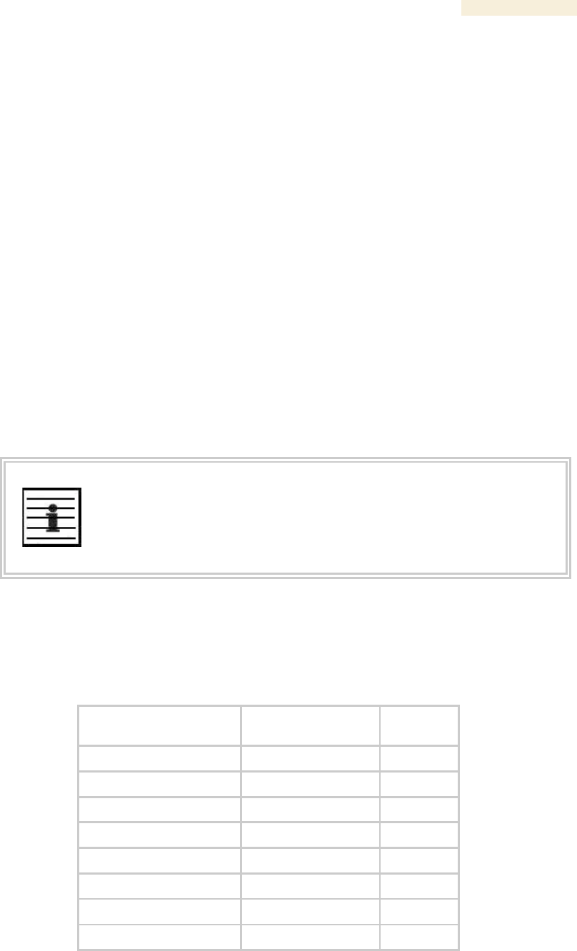
Release 8 Operations Guide
Issue 2, November 2007 Draft 5 for Regulatory Review 389
24.3 CONFIGURING MODULES FOR SNMP ACCESS
Canopy modules provide the following Configuration web page parameters in the SNMP
tab. These govern SNMP access from the manager to the agent:
◦ Community String, which specifies the password for security between
managers and the agent.
◦ Accessing Subnet, which specifies the subnet mask that allows managers to
poll the agents.
Canopy modules can also be configured to send traps to specified IP addresses, which
can be those of Prizm or NMS servers, for example. The parameter for this address is
named Trap Address.
24.4 OBJECTS DEFINED IN THE CANOPY ENTERPRISE MIB
The Canopy Enterprise MIB defines separate sets of objects for
◦ all radio modules
◦ APs and BH timing masters
◦ SMs and BH timing slaves
◦ CMMmicros
NOTE:
The PTP 400 and PTP 600 series bridges (previously known as 30/60 Mbps and
150/300 Mbps Backhauls) do not support these objects. The MIBs that they
support are listed under Objects Defined in the PTP 400 and PTP 600 series
Bridges MIB on Page 402.
24.4.1 AP, SM, and BH Objects
The objects that the Canopy Enterprise MIB defines for all APs, SMs, and BHs are listed
in Table 59.
Table 59: Canopy Enterprise MIB objects for APs, SMs, and BHs
AP, SM, BH
Object Name
Value Syntax
Operation
Allowed
addVlanMember
Integer
manage
agingTimeout
Integer
manage
allowVIDAccess
Integer
manage
antennaGain1
Integer
manage
bridgeEnable
Integer
manage
clearEventLog
Integer
manage
codePointn2
Integer
manage
commString
DisplayString
manage

Release 8 Operations Guide
Issue 2, November 2007 Draft 5 for Regulatory Review 390
AP, SM, BH
Object Name
Value Syntax
Operation
Allowed
deleteUser
DisplayString
manage
dynamicLearning
Integer
manage
eirp3
Integer
manage
extFilterDelay
Integer
manage
fecEnable
Integer
manage
lanDhcpState
Integer
manage
managementVID
Integer
manage
mngtIP
IpAddress
manage
powerControl
Integer
manage
reboot
Integer
manage
removeVlanMember
Integer
manage
scheduling
Integer
manage
sessionTimeout
Integer
manage
setDefaultPlug
Integer
manage
subnetMask
Integer
manage
taggedFrame4
Integer
manage
transmitterOP
Integer
manage
trapIPn5
IpAddress
manage
twoXRate
Integer
manage
userAccessLevel
Integer
manage
userName
DisplayString
manage
userPassword
DisplayString
manage
vlanMemberSource
Integer
manage
accessLevel
Integer
monitor
boxDeviceType
DisplayString
monitor
boxDeviceTypeID
DisplayString
monitor
boxEncryption
DisplayString
monitor
boxFrequency
DisplayString
monitor
boxTemperature6
DisplayString
monitor
dhcpLanIP
IpAddress
monitor
dhcpLanGateway
IpAddress
monitor
dhcpLanSubnetMask
IpAddress
monitor
dhcpRfPublicIP
IpAddress
monitor
dhcpRfPublicGateway
IpAddress
monitor

Release 8 Operations Guide
Issue 2, November 2007 Draft 5 for Regulatory Review 391
AP, SM, BH
Object Name
Value Syntax
Operation
Allowed
dhcpRfPublicSubnetMask
IpAddress
monitor
etherLinkStatus
DisplayString
monitor
inSyncCount
Integer
monitor
lanDhcpStatus
DisplayString
monitor
outSyncCount
Integer
monitor
platformType
Integer
monitor
platformVer
Integer
monitor
pllOutLockCount
Integer
monitor
rfPublicDhcpStatus
DisplayString
monitor
txCalFailure
Integer
monitor
userLoginName
DisplayString
monitor
userPswd
DisplayString
monitor
whispBoxBoot
DisplayString
monitor
whispBoxEsn
WhispMACAddress
monitor
whispBoxEvntLog
EventString
monitor
whispBoxFPGAVer
DisplayString
monitor
whispBridgeAge
Integer
monitor
whispBridgeDesLuid
WhispLUID
monitor
whispBridgeExt
Integer
monitor
whispBridgeHash
Integer
monitor
whispBridgeMacAddr
MacAddress
monitor
whispBridgeTbErr
Integer
monitor
whispBridgeTbFree
Integer
monitor
whispBridgeTbUsed
Integer
monitor
whispVAge
Integer
monitor

Release 8 Operations Guide
Issue 2, November 2007 Draft 5 for Regulatory Review 392
AP, SM, BH
Object Name
Value Syntax
Operation
Allowed
whispVID
Integer
monitor
whispVType
DisplayString
monitor
NOTES:
1. For only 5.7-GHz radios.
2. Where n is any number, 0 through 63. codePoint0,
codePoint48, and codePoint56 can be only monitored.
3. Deprecated.
4. Replaced by frameType.
5. Where n is any number, 1 through 10.
6. The value of this object does not accurately reflect the
temperature inside the module for comparison with the
operating range. However, it can be helpful as one of many
troubleshooting indicators. Although modules no longer
report the Temperature field in the GUI, the agent in the
modules continues to support this object.
24.4.2 AP and BH Timing Master Objects
The objects that the Canopy Enterprise MIB defines for each AP and BH Timing Master
are listed in Table 60. The traps provided in this set of objects are listed under Traps
Provided in the Canopy Enterprise MIB on Page 404.
Table 60: Canopy Enterprise MIB objects for APs and BH timing masters
AP, BHM
Object Name
Value Syntax
Operation
Allowed
allowedIPAccess1
IpAddress
manage
allowedIPAccess2
IpAddress
manage
allowedIPAccess3
IpAddress
manage
apBeaconInfo
Integer
manage
apTwoXRate
Integer
manage
asIP1
IpAddress
manage
asIP2
IpAddress
manage
asIP3
IpAddress
manage
authKey
DisplayString
manage
authMode
Integer
manage
configSource
Integer
manage
dAcksReservHigh
Integer
manage
defaultGw
IpAddress
manage
dfsConfig
Integer
manage
dwnLnkData
Integer
manage
dwnLnkDataRate
Integer
manage

Release 8 Operations Guide
Issue 2, November 2007 Draft 5 for Regulatory Review 393
AP, BHM
Object Name
Value Syntax
Operation
Allowed
dwnLnkLimit
Integer
manage
encryptDwBroadcast
Integer
manage
encryptionMode
Integer
manage
gpsInput
Integer
manage
gpsTrap
Integer
manage
highPriorityUpLnkPct
Integer
manage
ipAccessFilterEnable
Integer
manage
lanIp
IpAddress
manage
lanMask
IpAddress
manage
limitFreqBand900
Integer
manage
linkTestAction1
Integer
manage
linkTestDuration
Integer
manage
linkTestLUID
Integer
manage
maxRange
Integer
manage
ntpServerIP
IpAddress
manage
numCtlSlots
Integer
manage
numCtlSlotsHW
Integer
manage
numCtlSlotsReserveHigh
Integer
manage
numDAckSlots
Integer
manage
numUAckSlots
Integer
manage
privateIp
IpAddress
manage
regTrap
Integer
manage
rfFreqCarrier
Integer
manage
sectorID
Integer
manage
sesHiDownCIR
Integer
manage
sesHiUpCIR
Integer
manage
sesLoDownCIR
Integer
manage
sesHiDownCIR
Integer
manage
smIsolation
Integer
manage
tslBridging
Integer
manage
txSpreading
Integer
manage
uAcksReservHigh
Integer
manage
untranslatedArp
Integer
manage
updateAppAddress
IpAddress
manage

Release 8 Operations Guide
Issue 2, November 2007 Draft 5 for Regulatory Review 394
AP, BHM
Object Name
Value Syntax
Operation
Allowed
upLnkDataRate
Integer
manage
upLnkLimit
Integer
manage
vlanEnable
Integer
manage
actDwnFragCount
Gauge32
monitor
actDwnLinkIndex
Integer
monitor
actUpFragCount
Gauge32
monitor
adaptRate
DisplayString
monitor
avgPowerLevel
DisplayString
monitor
dataSlotDwn
Integer
monitor
dataSlotUp
Integer
monitor
dataSlotUpHi
Integer
monitor
dfsStatus
DisplayString
monitor
downLinkEff
Integer
monitor
downLinkRate
Integer
monitor
dwnLnkAckSlot
Integer
monitor
dwnLnkAckSlotHi
Integer
monitor
expDwnFragCount
Gauge32
monitor
expUpFragCount
Gauge32
monitor
fpgaVersion
DisplayString
monitor
gpsStatus
DisplayString
monitor
lastPowerLevel
DisplayString
monitor
linkAirDelay
Integer
monitor
linkAveJitter
Integer
monitor
linkDescr
DisplayString
monitor
linkESN
PhysAddress
monitor
linkInDiscards
Counter32
monitor
linkInError
Counter32
monitor
linkInNUcastPkts
Counter32
monitor
linkInOctets
Counter32
monitor
linkInUcastPkts
Counter32
monitor
linkInUnknownProtos
Counter32
monitor
linkLastJitter
Integer
monitor
linkLastRSSI
Integer
monitor
linkLUID
Integer
monitor

Release 8 Operations Guide
Issue 2, November 2007 Draft 5 for Regulatory Review 395
AP, BHM
Object Name
Value Syntax
Operation
Allowed
linkMtu
Integer
monitor
linkOutDiscards
Counter32
monitor
linkOutError
Counter32
monitor
linkOutNUcastPkts
Counter32
monitor
linkOutOctets
Counter32
monitor
linkOutQLen
Gauge32
monitor
linkOutUcastPkts
Counter32
monitor
linkRegCount
Integer
monitor
linkReRegCount
Integer
monitor
linkRSSI
Integer
monitor
linkSessState
Integer
monitor
linkSiteName
DisplayString
monitor
linkSpeed
Gauge32
monitor
linkTestError
DisplayString
monitor
linkTestStatus
DisplayString
monitor
linkTimeOut
Integer
monitor
maxDwnLinkIndex
Integer
monitor
numCtrSlot
Integer
monitor
numCtrSlotHi
Integer
monitor
PhysAddress
PhysAddress
monitor
radioSlicing
Integer
monitor
radioTxGain
Integer
monitor
regCount
Integer
monitor
sesDownlinkLimit
Integer
monitor
sesDownlinkRate
Integer
monitor
sesUplinkLimit
Integer
monitor
sesUplinkRate
Integer
monitor
sessionCount
Integer
monitor
softwareBootVersion
DisplayString
monitor
softwareVersion
DisplayString
monitor
testDuration
Integer
monitor
testLUID
Integer
monitor
upLinkEff
Integer
monitor
upLinkRate
Integer
monitor

Release 8 Operations Guide
Issue 2, November 2007 Draft 5 for Regulatory Review 396
AP, BHM
Object Name
Value Syntax
Operation
Allowed
upLnkAckSlot
Integer
monitor
upLnkAckSlotHi
Integer
monitor
whispGPSStats
Integer
monitor
NOTES:
1. You can set to 1 to initiate a link test, but not 0 to stop.
The value 0 is only an indication of the idle link test state.
24.4.3 SM and BH Timing Slave Objects
The objects that the Canopy Enterprise MIB defines for each SM and BH Timing Slave
are listed in Table 61.
Table 61: Canopy Enterprise MIB objects for SMs and BH timing slaves
SM, BHS
Object Name
Value Syntax
Operation
Allowed
allOtherIPFilter
Integer
manage
allOthersFilter
Integer
manage
allowedIPAccess1
IpAddress
manage
allowedIPAccess2
IpAddress
manage
allowedIPAccess3
IpAddress
manage
alternateDNSIP
IpAddress
manage
arpCacheTimeout
Integer
manage
arpFilter
Integer
manage
authKey
DisplayString
manage
authKeyOption
Integer
manage
bootpcFilter
Integer
manage
bootpsFilter
Integer
manage
defaultGw
IpAddress
manage
dhcpClientEnable
Integer
manage
dhcpIPStart
IpAddress
manage
dhcpNumIPsToLease
Integer
manage
dhcpServerEnable
Integer
manage
dhcpServerLeaseTime
Integer
manage
dmzEnable
Integer
manage
dmzIP
IpAddress
manage
dnsAutomatic
Integer
manage
enable8023link
Integer
manage

Release 8 Operations Guide
Issue 2, November 2007 Draft 5 for Regulatory Review 397
SM, BHS
Object Name
Value Syntax
Operation
Allowed
ethAccessFilterEnable
Integer
manage
hiPriorityChannel
Integer
manage
hiPriorityDownlinkCIR
Integer
manage
hiPriorityUplinkCIR
Integer
manage
ingressVID
Integer
manage
ip4MultFilter
Integer
manage
ipAccessFilterEnable
Integer
manage
lanIp
IpAddress
manage
lanMask
IpAddress
manage
localIP
IpAddress
manage
lowPriorityDownlinkCIR
Integer
manage
lowPriorityUplinkCIR
Integer
manage
naptEnable
Integer
manage
naptPrivateIP
IpAddress
manage
naptPrivateSubnetMask
IpAddress
manage
naptPublicGatewayIP
IpAddress
manage
naptPublicIP
IpAddress
manage
naptPublicSubnetMask
IpAddress
manage
naptRFPublicGateway
IpAddress
manage
naptRFPublicIP
IpAddress
manage
naptRFPublicSubnetMask
IpAddress
manage
networkAccess
Integer
manage
port
Integer
manage
port1TCPFilter
Integer
manage
port2TCPFilter
Integer
manage
port3TCPFilter
Integer
manage
port1UDPFilter
Integer
manage
port2UDPFilter
Integer
manage
port3UDPFilter
Integer
manage
powerUpMode
Integer
manage
pppoeFilter
Integer
manage
prefferedDNSIP
IpAddress
manage
protocol
Integer
manage
radioDbmInt
Integer
manage

Release 8 Operations Guide
Issue 2, November 2007 Draft 5 for Regulatory Review 398
SM, BHS
Object Name
Value Syntax
Operation
Allowed
rfDhcpState
Integer
manage
rfScanList
DisplayString
manage
smbFilter
Integer
manage
snmpFilter
Integer
manage
tcpGarbageCollectTmout
Integer
manage
timingPulseGated
Integer
manage
twoXRate
Integer
manage
udpGarbageCollectTmout
Integer
manage
uplinkBCastFilter
Integer
manage
userDefinedPort1
Integer
manage
userDefinedPort2
Integer
manage
userDefinedPort3
Integer
manage
userP1Filter
Integer
manage
userP2Filter
Integer
manage
userP3Filter
Integer
manage
adaptRate
DisplayString
monitor
airDelay
Integer
monitor
calibrationStatus
DisplayString
monitor
dhcpcdns1
IpAddress
monitor
dhcpcdns2
IpAddress
monitor
dhcpcdns3
IpAddress
monitor
dhcpCip
IpAddress
monitor
dhcpClientLease
TimeTicks
monitor
dhcpCSMask
IpAddress
monitor
dhcpDfltRterIP
IpAddress
monitor
dhcpDomName
DisplayString
monitor
dhcpServerTable
DhcpServerEntry
monitor
dhcpSip
IpAddress
monitor
hostIp
IpAddress
monitor
hostLease
TimeTicks
monitor
hostMacAddress
PhysAddress
monitor
jitter
Integer
monitor
radioDbm
DisplayString
monitor
radioSlicing
Integer
monitor

Release 8 Operations Guide
Issue 2, November 2007 Draft 5 for Regulatory Review 399
SM, BHS
Object Name
Value Syntax
Operation
Allowed
radioTxGain
Integer
monitor
registeredToAp
DisplayString
monitor
rssi
Integer
monitor
sessionStatus
DisplayString
monitor
24.4.4 CMMmicro Objects
The objects that the Canopy Enterprise MIB defines for each CMMmicro are listed in
Table 62.
Table 62: Canopy Enterprise MIB objects for CMMmicros
CMMmicro
Object Name
Value Syntax
Operation
Allowed
clearEventLog
Integer
manage
defaultGateWay
IpAddress
manage
displayOnlyAccess
DisplayString
manage
fullAccess
DisplayString
manage
gpsTimingPulse
Integer
manage
lan1Ip
IpAddress
manage
lan1SubnetMask
IpAddress
manage
port1Config
Integer
manage
port1Description
DisplayString
manage
port1PowerCtr
Integer
manage
port2Config
Integer
manage
port2Description
DisplayString
manage
port2PowerCtr
Integer
manage
port3Config
Integer
manage
port3Description
DisplayString
manage
port3PowerCtr
Integer
manage
port4Config
Integer
manage
port4Description
DisplayString
manage
port4PowerCtr
Integer
manage
port5Config
Integer
manage
port5Description
DisplayString
manage
port5PowerCtr
Integer
manage
port6Config
Integer
manage
port6Description
DisplayString
manage

Release 8 Operations Guide
Issue 2, November 2007 Draft 5 for Regulatory Review 400
CMMmicro
Object Name
Value Syntax
Operation
Allowed
port6PowerCtr
Integer
manage
port7Config
Integer
manage
port7Description
DisplayString
manage
port7PowerCtr
Integer
manage
port8Config
Integer
manage
port8Description
DisplayString
manage
port8PowerCtr
Integer
manage
reboot
Integer
manage
webAutoUpdate
Integer
manage
deviceType
DisplayString
monitor
displayOnlyStatus
DisplayString
monitor
duplexStatus
Integer
monitor
eventLog
EventString
monitor
fullAccessStatus
DisplayString
monitor
gpsAntennaConnection
DisplayString
monitor
gpsDate
DisplayString
monitor
gpsHeight
DisplayString
monitor
gpsInvalidMsg
DisplayString
monitor
gpsLatitude
DisplayString
monitor
gpsLongitude
DisplayString
monitor
gpsReceiverInfo
DisplayString
monitor
gpsRestartCount
Integer
monitor
gpsSatellitesTracked
DisplayString
monitor
gpsSatellitesVisible
DisplayString
monitor
gpsTime
DisplayString
monitor
gpsTrackingMode
DisplayString
monitor
height
DisplayString
monitor
latitude
DisplayString
monitor
linkSpeed
Integer
monitor
linkStatus
Integer
monitor
longitude
DisplayString
monitor
macAddress
DisplayString
monitor
pkts1024to1522Octets
Counter32
monitor
pkts128to255Octets
Counter32
monitor