Motorola Solutions 89FT7629 Access Point/CPE User Manual User Guide Part 2
Motorola Solutions, Inc. Access Point/CPE User Guide Part 2
Contents
- 1. User Guide Part 1
- 2. User Guide Part 2
- 3. User Guide Part 3
- 4. User Guide Part 4
- 5. User Guide Part 5
User Guide Part 2
Release 8 Overview of Canopy Networks
March 200 Through Software Release 6.
Issue 2, November 2007 Draft 5 for Regulatory Review 101
8.2 BH-BH LINKS
Canopy BHs communicate with each other using a point-to-point protocol. This point-to-
point protocol uses a 2.5-msec frame. A BH link has higher throughput and lower latency
(typically 5 msec, 2.5 msec in each direction) for two reasons:
◦ Only two endpoints are involved.
◦ No bandwidth request and reservation process is involved.
For 10-Mbps BHs, the aggregate throughput on the channel is 7.5 Mbps. For 20-Mbps
BHs, the aggregate throughput on the channel is 14 Mbps. If a BH is set to a downlink
ratio of 50%, then the bandwidth in each direction is half of the total BH link bandwidth.
Release 8 Overview of Canopy Networks
March 200 Through Software Release 6.
Issue 2, November 2007 Draft 5 for Regulatory Review 103
9 PREVIEWING NETWORK CONFIGURATIONS
The following are examples of network layouts. Customer experience case studies are
also available.
9.1 VIEWING TYPICAL LAYOUTS
The following layouts are typical of Canopy system implementations:
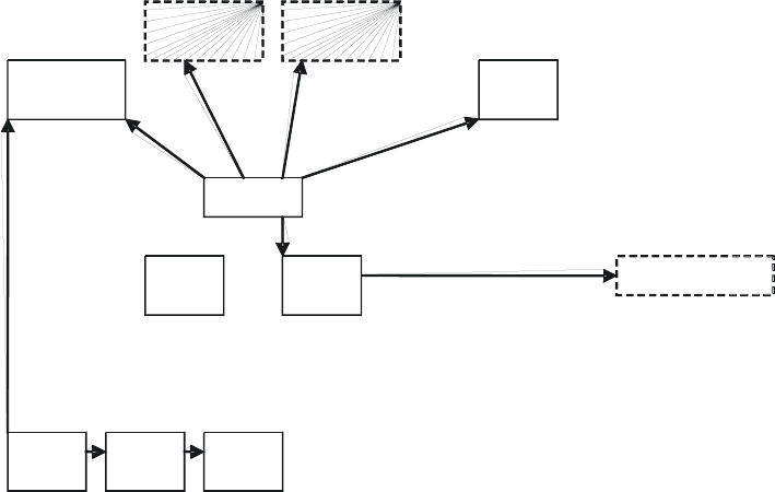
◦ Figure 28: Typical network layout with no BH
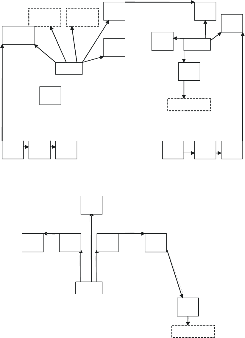
◦ Figure 29: Typical network layout with BH
◦ Figure 30: Typical multiple-BH network layout
PCRTRSM
WAN (Internet)
CMM
RTR
GPS
BAM
AP
Cluster 2
AP
Cluster 1
AP
Cluster 3
Figure 28: Typical network layout with no BH
Release 8 Overview of Canopy Networks
March 200 Through Software Release 6.
Issue 2, November 2007 Draft 5 for Regulatory Review 104
Figure 29: Typical network layout with BH
BHS
RTR
WAN (Internet)
CMM
GPS
BHM BHM BHS
Figure 30: Typical multiple-BH network layout
P
C
R
T
R
S
M
B
H
S
B
H
M
C
M
M
G
P
S
B
A
M
A
P
C
l
u
s
t
e
r
2
A
P
C
l
u
s
t
e
r
1
A
P
C
l
u
s
t
e
r
3
C
M
M
R
T
R
A
P
S
M
R
T
R
P
C
W
A
N
(
I
n
t
e
r
n
e
t
)
G
P
S

Release 8 Overview of Canopy Networks
March 200 Through Software Release 6.
Issue 2, November 2007 Draft 5 for Regulatory Review 105
9.2 VIEWING CASE STUDIES
Case studies of Canopy implementations are available as “Feature Articles” for download
from http://www.connectwithcanopy.com/index.cfm?canopy=menu.case.

Release 8 Overview of Canopy Networks
March 200 Through Software Release 6.
Issue 2, November 2007 Draft 5 for Regulatory Review 107
10 ACCESSING FEATURES
Canopy Release 8 networks support the features that are indicated in Table 26.
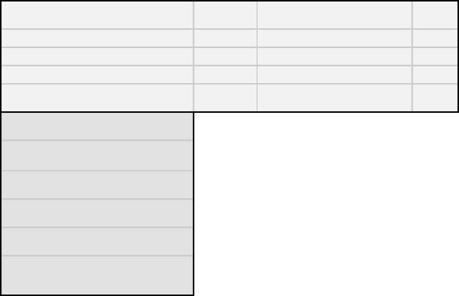
Table 26: Canopy features
Regulatory Features
Module
Type(s)
Controlled in GUI Page/Tab
SNMP
Control
RoHS compliant (EU “green” mandate)
All modules
no
no
WEEE compliant
All modules
no
no
Complies with Human RF exposure limits
(ETSI)
All radios
no
no
Radio Features
Module
Type(s)
Controlled in GUI Page/Tab
SNMP
Control
Time Division Duplex
All radios
no
no
Scalable up to 6 sectors per cell.
AP SM
no
no
200 registered subscribers supported per AP
AP SM
no
no
Fixed /nomadic operation
All radios
no
no
20 ms or less round trip latency (OTA with
Canopy MAC, under normal conditions)
All radios
no
no
Transmit frame spreading for geographical
area co-existence
AP BHM
Configuration/Radio
yes
Radio statistics (scheduler)
All radios
Statistics/Scheduler
yes
2X rate, enabled per link (requires
Advantage AP or 20 Mbps BH)
SM BHS
Configuration/General
yes
2X rate, enabled per sector (requires
Advantage AP or 20 Mbps BH )
AP BHM
Configuration/General
yes
Manual transmit power control - normal and
low (-18 dB)
All radios
Configuration/Radio
yes
Manual transmit power control, 1 dB
increments over 25 dB at the AP
AP BHM
Configuration/Radio
yes

Release 8 Overview of Canopy Networks
March 200 Through Software Release 6.
Issue 2, November 2007 Draft 5 for Regulatory Review 108
RF Configuration Features
Module
Type(s)
Controlled in GUI Page/Tab
SNMP
Control
Configurable center-channel carrier
frequency
AP BHM
Configuration/Radio
yes
255 configurable "color codes" to manage
SM to AP (or (BHS to BHM) registration
All radios
Configuration/Radio
yes
16 configurable "sector IDs" for
administrative convenience
AP BHM
Configuration/Radio
yes
Configurable range settings (determines air
turn-around time)
AP
Configuration/Radio
yes
Configurable downlink data % (determines
transmit/receive ratio)
AP BHM
Configuration/Radio
yes
Configurable number of reserved control
slots (manages contention for uplink
requests)
AP
Configuration/Radio
yes
Configurable frequency scan list at SM
SM BHS
Configuration/Radio
yes
Packet stats - RF interface
All radios
Statistics/Radio
yes
Timing Features
Module
Type(s)
Controlled in GUI Page/Tab
SNMP
Control
Configurable AP/BHM sync source - Sync
over Power over Ethernet, self-sync, or sync
cable
AP BHM
Configuration/General
yes
"Remote AP" support, including timing pulse
propagation through SM/BHS
SM BHS
Configuration/General
yes
Ethernet Interface Features
Module
Type(s)
Controlled in GUI Page/Tab
SNMP
Control
Selectable link speeds - 10/100 Base T, half,
full-duplex
All modules
Configuration/General
yes
Ethernet link auto-negotiation
All modules
Configuration/General
no
Accepts straight-through or crossover
Ethernet cable wiring (Auto-MDX)
All modules
no
no
Wire line Interface: Ethernet cable with
proprietary PoE
All modules
no
no
Disable SM Ethernet link
SM
Configuration/General
yes
Packet stats - Ethernet interface
All radios
Statistics/Ethernet
yes

Release 8 Overview of Canopy Networks
March 200 Through Software Release 6.
Issue 2, November 2007 Draft 5 for Regulatory Review 109
IP Interface Features
Module
Type(s)
Controlled in GUI Page/Tab
SNMP
Control
Configurable LAN settings (IP address,
mask, gateway)
All radios
Configuration/IP
yes
Module's management IP address
assignable via DHCP
All radios
Configuration/IP
yes
Private LAN to support AP to SM (or BHM to
BHS) communications
All radios
Configuration/IP
yes
Configurable SM mgmt accessibility
(Local/Ethernet only, or Public/RF and
Local/Ethernet)
SM
Configuration/IP
yes
Security Features (Authentication,
Encryption, and Access Control)
Module
Type(s)
Controlled in GUI Page/Tab
SNMP
Control
Configurable SM authentication using
BAM/PrizmEMS
AP SM
Configuration/Security
yes
Configurable BH authentication, standalone
BHM BHS
Configuration/Security
no
DES encryption on standard product
All radios
no
yes
AES encryption on AES product
All radios
no
yes
Configurable whether SM/BHS displays
AP/BHM beacon information
AP BHM
Configuration/Security
yes
Configurable web, telnet, and ftp session
timeout
All radios
Configuration/Security
yes
Configurable access to radio management -
up to 3 source IP addresses
All radios
Configuration/Security
yes
User/account names (up to 4) and
passwords on modules
All radios
Account
yes
Permission levels control ability to add/delete
users/passwords
All radios
Account
yes
Override plug to override lost IP address or
user/password
All radios
no
no
Override plug configurable as a default plug -
reset to factory defaults
AP SM
BHM BHS
Configuration/Unit Settings
yes
Override switch to override lost IP address or
user/password on CMM
CMMmicro
no
no

Release 8 Overview of Canopy Networks
March 200 Through Software Release 6.
Issue 2, November 2007 Draft 5 for Regulatory Review 110
Monitoring Features
Module
Type(s)
Controlled in GUI Page/Tab
SNMP
Control
List of registered SMs/BHSs with full data,
with hot links to SMs/BHSs
AP BHM
Configuration/General
multiple
objects
Abbreviated list of SMs/BHSs, with hot links
to SMs/BHSs
AP BHM
Configuration/General
multiple
objects
Received power level indication
All radios
Configuration/General
yes
LEDs on modules to display states and
activity
All modules
no
no
Received interference level indication (jitter)
All radios
Configuration/General
yes
Configurable web-page auto-refresh
All modules
Configuration/General
yes
SM registration failures
AP BHM
Statistics/Reg Failures
yes
Event log
All modules
Home/Event Log
no
Operator can use own logo on GUI pages
All modules
no
yes
Operator can use own style sheets for GUI
All modules
no
yes
Bridge Management Features
Module
Type(s)
Controlled in GUI Page/Tab
SNMP
Control
Configurable bridge entry timeout
All radios
Configuration/General
yes
Bridging table statistics (up to 4096 entries)
All radios
Statistics/Bridging Table
yes
Disable bridging on BHs
BHM BHS
Configuration/General
yes
SM Isolation Features (preventing
communication between SMs)
Module
Type(s)
Controlled in GUI Page/Tab
SNMP
Control
SM isolation at AP
AP
Configuration/General
yes
SM isolation at CMM
CMMmicro
Configuration/General
yes
SM Isolation Features
Module
Type(s)
Controlled in GUI Page/Tab
SNMP
Control
Translation bridging (replace customer MAC
with SM MAC address)
AP
Configuration/General
yes
With Translation bridging, choice of sending
untranslated ARP
AP
Configuration/General
yes
Translation table statistics
All radios
Statistics/Translation Table
yes
Quick Start Feature
Module
Type(s)
Controlled in GUI Page/Tab
SNMP
Control
AP configuration quick-start wizard
AP BHM
Quick Start

Release 8 Overview of Canopy Networks
March 200 Through Software Release 6.
Issue 2, November 2007 Draft 5 for Regulatory Review 111
Bandwidth Management Features
Module
Type(s)
Controlled in GUI Page/Tab
SNMP
Control
AP Maximum Information Rate (MIR) default
settings
AP
Configuration/QoS
yes
Per SM Maximum Information Rate (MIR)
SM
Configuration/QoS
yes
Per SM Committed Information Rate (CIR)
for high and low channels
SM
Configuration/QoS
yes
"Configuration Source" for
MIR/CIR/HP/VLAN can be either SM or
BAM/Prizm
AP
Configuration/General
yes
CIR for low priority channel on BH
BHS
Configuration/QoS
yes
Configurable priority for TCP Acks, to
optimize bandwidth use
AP BHM
Configuration/General
yes
Bandwidth Management Features
Module
Type(s)
Controlled in GUI Page/Tab
SNMP
Control
Configurable High Priority channel with
configurable DiffServ mappings on AP, SM
(2 classes of service)
AP SM
Configuration/DiffServe
yes
Permanent BH High Priority Channel with
configurable DiffServ mappings on BH
(2 classes of service)
BHM BHS
Configuration/DiffServe
yes
Virtual channel (high/low priority) statistics
All radios
Statistics/Data VC
yes
Network Address Translation (NAT)
Features
Module
Type(s)
Controlled in GUI Page/Tab
SNMP
Control
NAT
SM
Configuration/NAT
yes
NAT DMZ
SM
Configuration/NAT
yes
NAT DHCP server on LAN with up to 254 IP
addresses in pool
SM
Configuration/NAT
yes
NAT DHCP client on WAN (obtains NAT
address from a DHCP server)
SM
Configuration/NAT
yes
NAT port mapping
SM
Configuration/NAT
yes
VPN "pass through" for L2TP over IPSec
(but not PPTP)
no
no
NAT statistics
SM
Statistics/NAT Stats
yes
NAT DHCP statistics
SM
Statistics/NAT DHCP Statistics
yes
NAT table
SM
Logs/NAT Table
no
Filtering Features
Module
Type(s)
Controlled in GUI Page/Tab
SNMP
Control
Protocol filtering based on protocol
SM
Configuration/Protocol Filtering
yes
Operator-defined port filtering (3 ports)
SM
Configuration/Protocol Filtering
yes
Packet filter statistics
All radios
Statistics/Filter
yes

Release 8 Overview of Canopy Networks
March 200 Through Software Release 6.
Issue 2, November 2007 Draft 5 for Regulatory Review 112
VLAN Management Features
Module
Type(s)
Controlled in GUI Page/Tab
SNMP
Control
Configurable VLAN
AP SM
CMMmicro
Configuration/VLAN
yes
Highly configurable VLAN (802.1Q)
AP SM
Configuration/VLAN
yes
Use of VLAN priorities (802.1p) with high
priority channel
AP SM
no
yes
Port-based VLAN switching on CMM
CMMmicro
Configuration
yes
VLAN statistics
AP SM
Statistics/VLAN
yes
Dynamic Frequency Selection (DFS)
Feature
Module
Type(s)
Controlled in GUI Page/Tab
SNMP
Control
DFS v1.2.3
All radios
no
yes
Time Features
Module
Type(s)
Controlled in GUI Page/Tab
SNMP
Control
Time and Date from CMM via Network Time
Protocol (NTP) server
AP BHM
Configuration/Time
yes
Time and Date manually settable
AP BHM
Configuration/Time
yes
CMM provides NTP server
CMMmicro
no
no
Spectrum Analyzer Features
Module
Type(s)
Controlled in GUI Page/Tab
SNMP
Control
Spectrum analyzer
SM BHS
Tools/Spectrum Analyzer
no
Ability to switch an AP to an SM (or BHS to
BHM)
AP BHM
Configuration/General
yes
Aim/Link Quality Features
Module
Type(s)
Controlled in GUI Page/Tab
SNMP
Control
Alignment tone for using during
aiming/alignment
SM BHS
no
no
Aiming support page when not using
alignment tone
SM BHS
Tools/Alignment
multiple
objects
LED for alignment
SM BHS
no
no
Configure SM power-up state - aiming or
operational
SM BHS
Configuration/General
yes
Link capacity test, with configurable packet
length
All radios
Tools/Link Capacity Test
yes
Display of SM configuration information at
AP
AP BHM
Home/Session Status
yes
Display/evaluation of AP beacon data from
all receivable APs
SM BHS
Tools/AP Evaluation
yes
Over-the-air radio Bit Error Rate (BER)
indicator
All radios
Tools/BER Results
yes

Release 8 Overview of Canopy Networks
March 200 Through Software Release 6.
Issue 2, November 2007 Draft 5 for Regulatory Review 113
Frame Tool Feature
Module
Type(s)
Controlled in GUI Page/Tab
SNMP
Control
Frame calculator for supporting collocation
All radios
Tools/Frame Calculator
no
Personal Digital Assistant (PDA)
Interface Features
Module
Type(s)
Controlled in GUI Page/Tab
SNMP
Control
GUI automatically sized/styled for PDA when
displayed on a PDA
All radios
all
no
Spectrum analyzer display for PDA
All radios
PDA/Spectrum Results (PDA)
no
Specific pages for PDA display
All radios
PDA
no
SNMP Interface Features
Module
Type(s)
Controlled in GUI Page/Tab
SNMP
Control
Support of SNMP v2
All modules
no
no
Canopy Enterprise MIB
All modules
no
no
Configurable SNMP community string
All radios
Configuration/SNMP
yes
Configurable SNMP accessing subnet
All radios
Configuration/SNMP
yes
10 configurable SNMP trap addresses
All radios
Configuration/SNMP
yes
Configurable traps (sync and session)
All radios
Configuration/SNMP
yes
Configurable SNMP permissions (read,
read/write)
All radios
Configuration/SNMP
yes
Configurable site information, including site
name
All modules
Configuration/SNMP
yes
Upgrade Process Features
Module
Type(s)
Controlled in GUI Page/Tab
SNMP
Control
Upgrading using CNUT and SM Auto-update
for SMs
All modules
no
no
Configurable update address to support
distributed software upgrades
AP
Configuration/General
yes
AP Cluster Management Features
Module
Type(s)
Controlled in GUI Page/Tab
SNMP
Control
CMM port power control
CMMmicro
Configuration
yes
CMM port reset
CMMmicro
Configuration
yes
CMM: Sufficient ports for at least 4 AP, 2
BH, plus management
CMMmicro
no
no
CMM: Sufficient power for at least 4 AP plus
2 BH
CMMmicro
no
no
Powered from 90-264 VAC, 50/60 Hz; 55 V
DC power output
AP BH
no
no
Release 8 Overview of Canopy Networks
March 200 Through Software Release 6.
Issue 2, November 2007 Draft 5 for Regulatory Review 114
Physical Features
Module
Type(s)
Controlled in GUI Page/Tab
SNMP
Control
MTBF > 45 years (~400 000 hours)
All modules
no
no
neg 40 C to + 55 C (Ambient) operation
All modules
no
no
Temperature indication
All radios
Home/General
no
Non-condensing (Indoor/outdoor), weather
protected form factor/packaging
All modules
no
no
Element Management System (Prizm)
Features
Current Prizm to manage all elements of the
system (including Mot Backhaul)
Up to 1000 APs, plus 100 devices/AP);
minimal storage / minimal polling
Redundant configuration for additional
storage/reporting capability
Commercial Off the Shelf (COTS) Platform
and OS support (e.g. Intel, Linux, Windows)
COTS Database support (e.g. MySQL,
PostgreSQL, MS SQL Server, etc..); Oracle
optional
10.1 ACTIVATING FEATURES
A Canopy feature is active if the software that allows the feature to be turned on or off
(enabled or disabled) is present.
10.1.1 Fixed License Keys
Some features are activated by loading a fixed license key into the radio. Such a key
arrives from Motorola as a filename.url file. When you double-click on this file, your
browser opens and the location bar is populated by a lengthy string. This URL string
begins with http://<ModuleIPAddress>/. If you need to load a key into a module
whose IP address has changed since Motorola issued the key, perform the following
steps.
Procedure 1: Modifying a fixed license key for a module IP address
1. Right-click on the license key filename.
2. Select Properties.
3. Select the Web Document tab.
4. At URL, substitute the current IP address for the original IP address in the URL.
5. Click OK.
6. Double-click on the license key filename.
RESULT: The key loads into the module.
Release 8 Overview of Canopy Networks
March 200 Through Software Release 6.
Issue 2, November 2007 Draft 5 for Regulatory Review 115
7. Open the Configuration web page of the module.
8. Review parameter settings and enable the feature if you wish to do so at this
time (see next section).
=========================== end of procedure ===========================
10.2 ENABLING FEATURES
A Canopy feature is enabled (functioning) if the feature is both active and enabled. For
example, Transmit Frame Spreading is active (can be enabled) in any AP or BHM that
operates on Release 8. However, Transmit Frame Spreading functions only if the Enable
selection for the Transmit Frame Spreading parameter is checked in the Radio tab of
the Configuration web page in the module.

Release 8 Overview of Canopy Networks
March 200 Through Software Release 6.
Issue 2, November 2007 Draft 5 for Regulatory Review 117
11 ACQUIRING PROFICIENCIES
Designing and operating a Canopy network requires fundamental knowledge of radio
frequency transmission and reception, Internet Protocol addressing schemes,
experimentation with Canopy equipment, and for most operators participation in some
forms of Canopy training.
11.1 UNDERSTANDING RF FUNDAMENTALS
Canopy training and user interfaces presume an understanding of RF fundamentals.
Excellent written sources for these fundamentals are available. One such source is
Deploying License-Free Wireless Wide-Area Networks by Jack Unger (ISBN 1-58705-
069-2), published by Cisco Press.
11.2 UNDERSTANDING IP FUNDAMENTALS
Canopy training and user interfaces also presume an understanding of Internet Protocol
(IP) fundamentals. Excellent written sources for these fundamentals are available. One
such source is Sams Teach Yourself TCP/IP in 24 Hours by Joe Casad
(ISBN 0-672-32085-1), published by Sams Publishing.
NOTE:
The default IP address of each Canopy component is 169.254.1.1.
11.3 ACQUIRING A CANOPY DEMONSTRATION KIT
Canopy Demonstration Kits are available through your Canopy representative.
11.3.1 900-MHz with Integrated Antenna and Band-pass Filter Demonstration Kit
Each 900-MHz with integrated antenna and band-pass filter Demonstration Kit contains
◦ 2 9000SM SMs
◦ 1 9000APF AP
◦ 1 300SS Surge Suppressor
◦ 3 ACPSSW-02 90- to 230-V AC 50- to 60-Hz Power Supplies
◦ 3 CBL-0562 Straight-through Category 5 Cables
◦ 1 UGTK-0002 Trial Kit Quick Start Guide
◦ 1 CPT001-CD02EN Sales Overview on CD
◦ 1 CPT002-CD03EN Technical Overview on CD
◦ 1 CPT003-CD03EN Canopy User Guides on CD
Part numbers for Demonstration Kits are provided in Table 27.
11.3.2 900-MHz with Connectorized Antenna Demonstration Kit
Each 900-MHz with connectorized (external) antenna Demonstration Kit contains
◦ 2 9000SMC SMs
Release 8 Overview of Canopy Networks
March 200 Through Software Release 6.
Issue 2, November 2007 Draft 5 for Regulatory Review 118
◦ 1 9000APC AP
◦ 3 AN900 60° 9-dBi Antennas
◦ 1 300SS Surge Suppressor
◦ 1 SMMB2 Universal Heavy Duty Mounting Bracket
◦ 3 ACPSSW-02 90- to 230-V AC 50- to 60-Hz Power Supplies
◦ 3 CBL-0562 Straight-through Category 5 Cables
◦ 1 UGTK-0002 Trial Kit Quick Start Guide
◦ 1 CPT001-CD02EN Sales Overview on CD
◦ 1 CPT002-CD03EN Technical Overview on CD
◦ 1 CPT003-CD03EN Canopy User Guides on CD
Part numbers for Demonstration Kits are provided in Table 27.
11.3.3 2.4-GHz with Adjustable Power Set to Low Demonstration Kit
Each 2.4-GHz with adjustable power set to low Demonstration Kit contains
◦ 1 2400SMWL SM
◦ 1 2450SMWL Advantage SM
◦ 1 2450APWL Advantage AP
◦ 1 300SS Surge Suppressor
◦ 1 SMMB1 Universal Mounting Bracket
◦ 3 ACPSSW-02 90- to 230-V AC 50- to 60-Hz Power Supplies
◦ 3 CBL-0562 Straight-through Category 5 Cables
◦ 1 UGTK-0002 Trial Kit Quick Start Guide
◦ 1 CPT001-CD02EN Sales Overview on CD
◦ 1 CPT002-CD03EN Technical Overview on CD
◦ 1 CPT003-CD03EN Canopy User Guides on CD
Part numbers for Demonstration Kits are provided in Table 27.
11.3.4 2.4-GHz with Adjustable Power Set to High Demonstration Kit
Each 2.4-GHz with adjustable power set to high Demonstration Kit contains
◦ 1 2400SM SM
◦ 1 2450SM Advantage SM
◦ 1 2450AP Advantage AP
◦ 1 300SS Surge Suppressor
◦ 1 SMMB1 Universal Mounting Bracket
◦ 3 ACPSSW-02 90- to 230-V AC 50- to 60-Hz Power Supplies
◦ 3 CBL-0562 Straight-through Category 5 Cables
◦ 1 UGTK-0002 Trial Kit Quick Start Guide
◦ 1 CPT001-CD02EN Sales Overview on CD
◦ 1 CPT002-CD03EN Technical Overview on CD
◦ 1 CPT003-CD03EN Canopy User Guides on CD
Part numbers for Demonstration Kits are provided in Table 27.
Release 8 Overview of Canopy Networks
March 200 Through Software Release 6.
Issue 2, November 2007 Draft 5 for Regulatory Review 119
11.3.5 5.1-GHz Demonstration Kit
Each 5.1-GHz Demonstration Kit contains
◦ 1 5202SM SM
◦ 1 5252SM Advantage SM
◦ 1 5252AP Advantage AP
◦ 1 300SS Surge Suppressor
◦ 1 SMMB1 Universal Mounting Bracket
◦ 3 ACPSSW-02 90- to 230-V AC 50- to 60-Hz Power Supplies
◦ 3 CBL-0562 Straight-through Category 5 Cables
◦ 1 UGTK-0002 Trial Kit Quick Start Guide
◦ 1 CPT001-CD02EN Sales Overview on CD
◦ 1 CPT002-CD03EN Technical Overview on CD
◦ 1 CPT003-CD03EN Canopy User Guides on CD
Part numbers for Demonstration Kits are provided in Table 27.
11.3.6 5.2-GHz Demonstration Kit
Each 5.2-GHz Demonstration Kit contains
◦ 1 5200SM SM
◦ 1 5250SM Advantage SM
◦ 1 5250AP Advantage AP
◦ 1 300SS Surge Suppressor
◦ 1 SMMB1 Universal Mounting Bracket
◦ 3 ACPSSW-02 90- to 230-V AC 50- to 60-Hz Power Supplies
◦ 3 CBL-0562 Straight-through Category 5 Cables
◦ 1 UGTK-0002 Trial Kit Quick Start Guide
◦ 1 CPT001-CD02EN Sales Overview on CD
◦ 1 CPT002-CD03EN Technical Overview on CD
◦ 1 CPT003-CD03EN Canopy User Guides on CD
Part numbers for Demonstration Kits are provided in Table 27.
11.3.7 5.4-GHz Demonstration Kit
Each 5.4-GHz Demonstration Kit contains
◦ 1 5400SM SM
◦ 1 5450SM Advantage SM
◦ 1 5450AP Advantage AP
◦ 1 300SS Surge Suppressor
◦ 1 SMMB1 Universal Mounting Bracket
◦ 3 ACPSSW-02 90- to 230-V AC 50- to 60-Hz Power Supplies
◦ 3 CBL-0562 Straight-through Category 5 Cables
◦ 1 UGTK-0002 Trial Kit Quick Start Guide
◦ 1 CPT001-CD02EN Sales Overview on CD
Release 8 Overview of Canopy Networks
March 200 Through Software Release 6.
Issue 2, November 2007 Draft 5 for Regulatory Review 120
◦ 1 CPT002-CD03EN Technical Overview on CD
◦ 1 CPT003-CD03EN Canopy User Guides on CD
Part numbers for Demonstration Kits are provided in Table 27.
11.3.8 5.7-GHz with Integrated Antenna Demonstration Kit
Each 5.7-GHz with integrated antenna Demonstration Kit contains
◦ 1 5700SM SM
◦ 1 5750SM Advantage SM
◦ 1 5750AP Advantage AP
◦ 1 300SS Surge Suppressor
◦ 1 SMMB1 Universal Mounting Bracket
◦ 3 ACPSSW-02 90- to 230-V AC 50- to 60-Hz Power Supplies
◦ 3 CBL-0562 Straight-through Category 5 Cables
◦ 1 UGTK-0002 Trial Kit Quick Start Guide
◦ 1 CPT001-CD02EN Sales Overview on CD
◦ 1 CPT002-CD03EN Technical Overview on CD
◦ 1 CPT003-CD03EN Canopy User Guides on CD
Part numbers for Demonstration Kits are provided in Table 27.
11.3.9 5.7-GHz with Connectorized Antenna and Adjustable Power Set to Low
Each 5.7-GHz with connectorized antenna and adjustable power set to low
Demonstration Kit contains
◦ 1 5700SMC SM
◦ 1 5750SMC Advantage SM
◦ 1 5750APC Advantage AP
◦ 1 300SS Surge Suppressor
◦ 1 SMMB2 Universal Heavy Duty Mounting Bracket
◦ 3 ACPSSW-02 90- to 230-V AC 50- to 60-Hz Power Supplies
◦ 3 CBL-0562 Straight-through Category 5 Cables
◦ 1 UGTK-0002 Trial Kit Quick Start Guide
◦ 1 CPT001-CD02EN Sales Overview on CD
◦ 1 CPT002-CD03EN Technical Overview on CD
◦ 1 CPT003-CD03EN Canopy User Guides on CD
Part numbers for Demonstration Kits are provided in Table 27.
11.3.10 Demonstration Kit Part Numbers
The part numbers for ordering Canopy demonstration kits are provided in Table 27.

Release 8 Overview of Canopy Networks
March 200 Through Software Release 6.
Issue 2, November 2007 Draft 5 for Regulatory Review 121
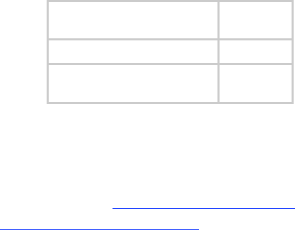
Table 27: Demonstration Kit part numbers
Frequency
Band Range
Part
Number
900 MHz integrated antenna
with band-pass filter
TK10290
900 MHz connectorized
antenna
TK10290C
2.4 GHz adjustable power
set to low
TK10250
2.4 GHz adjustable power
set to high
TK10251
5.1 GHz
TK10253
5.2 GHz
TK10252
5.4 GHz
TK10254
5.7 GHz
TK10257
5.7 GHz connectorized
adjustable power set to low
TK10257C
11.4 ACQUIRING A CANOPY STARTER KIT
Canopy Starter Kits are also available through your Canopy representative.
11.4.1 900-MHz with Integrated Antenna and Band-pass Filter Starter Kit
Each 900-MHz with integrated antenna and band-pass filters Starter Kit contains
◦ 20 9000SM SMs
◦ 3 9000APF Advantage APs
◦ 1 1070CK CMMmicro
◦ 21 300SS Surge Suppressors
◦ 1 UGSK-0003 Quick Start Guide
◦ 1 CPT003-CD03EN Canopy User Guides on CD
Power supplies and SM mounting brackets are not included in this kit. Part numbers for
Starter Kits are provided in Table 28.
Release 8 Overview of Canopy Networks
March 200 Through Software Release 6.
Issue 2, November 2007 Draft 5 for Regulatory Review 122
11.4.2 900-MHz with Connectorized Antenna Starter Kit
Each 900-MHz with connectorized (external) antenna Starter Kit contains
◦ 20 9000SMC SMs
◦ 3 9000APC Advantage APs
◦ 23 AN900 60° 9-dBi Antennas
◦ 1 1070CK CMMmicro
◦ 21 300SS Surge Suppressors
◦ 20 SMMB2 Universal Heavy Duty Mounting Brackets
◦ 1 UGSK-0003 Quick Start Guide
◦ 1 CPT003-CD03EN Canopy User Guides on CD
Power supplies are not included in this kit. Part numbers for Starter Kits are provided in
Table 28.
11.4.3 2.4-GHz with Adjustable Power Set to Low Starter Kit
Each 2.4-GHz with adjustable power set to low Starter Kit contains
◦ 30 2400SMWL SMs
◦ 6 2450APWL Advantage APs
◦ 1 1070CK CMMmicro
◦ 31 300SS Surge Suppressors
◦ 30 SMMB1 Universal Mounting Brackets
◦ 1 UGSK-0003 Quick Start Guide
◦ 1 CPT003-CD03EN Canopy User Guides on CD
Power supplies are not included in this kit. Part numbers for Starter Kits are provided in
Table 28.
11.4.4 2.4-GHz with Adjustable Power Set to High Starter Kit
Each 2.4-GHz adjustable power set to high Starter Kit contains
◦ 30 2400SM SMs
◦ 6 2450AP Advantage APs
◦ 1 1070CK CMMmicro
◦ 31 300SS Surge Suppressors
◦ 30 SMMB1 Universal Mounting Brackets
◦ 1 UGSK-0003 Quick Start Guide
◦ 1 CPT003-CD03EN Canopy User Guides on CD
Power supplies are not included in this kit. Part numbers for Starter Kits are provided in
Table 28.
Release 8 Overview of Canopy Networks
March 200 Through Software Release 6.
Issue 2, November 2007 Draft 5 for Regulatory Review 123
11.4.5 5.1-GHz Starter Kit
Each 5.1-GHz adjustable power set to high Starter Kit contains
◦ 30 5202SM SMs
◦ 6 5252AP Advantage APs
◦ 1 1070CK CMMmicro
◦ 31 300SS Surge Suppressors
◦ 30 SMMB1 Universal Mounting Brackets
◦ 1 UGSK-0003 Quick Start Guide
◦ 1 CPT003-CD03EN Canopy User Guides on CD
Power supplies are not included in this kit. Part numbers for Starter Kits are provided in
Table 28.
11.4.6 5.2-GHz Starter Kit
Each 5.2-GHz Starter Kit contains
◦ 30 5200SM SMs
◦ 6 5250AP Advantage APs
◦ 1 1070CK CMMmicro
◦ 31 300SS Surge Suppressors
◦ 30 SMMB1 Universal Mounting Brackets
◦ 1 UGSK-0003 Quick Start Guide
◦ 1 CPT003-CD03EN Canopy User Guides on CD
Power supplies are not included in this kit. Part numbers for Starter Kits are provided in
Table 28.
11.4.7 5.4-GHz Starter Kit
Each 5.4-GHz Starter Kit contains
◦ 30 5400SM SMs
◦ 6 5450AP Advantage APs
◦ 1 1070CK CMMmicro
◦ 31 300SS Surge Suppressors
◦ 30 SMMB1 Universal Mounting Brackets
◦ 1 UGSK-0003 Quick Start Guide
◦ 1 CPT003-CD02EN Canopy System User Guide on CD
Power supplies are not included in this kit. Part numbers for Starter Kits are provided in
Table 28.

Release 8 Overview of Canopy Networks
March 200 Through Software Release 6.
Issue 2, November 2007 Draft 5 for Regulatory Review 124
11.4.8 5.7-GHz with Integrated Antenna Starter Kit
Each 5.7-GHz with integrated antenna Starter Kit contains
◦ 30 5700SM SMs
◦ 6 5750AP Advantage APs
◦ 1 1070CK CMMmicro
◦ 31 300SS Surge Suppressors
◦ 30 SMMB1 Universal Mounting Brackets
◦ 1 UGSK-0003 Quick Start Guide
◦ 1 CPT003-CD03EN Canopy User Guides on CD
Power supplies are not included in this kit. Part numbers for Starter Kits are provided in
Table 28.
11.4.9 5.7-GHz with Connectorized Antenna and Adjustable Power Set to Low
Each 5.7-GHz with connectorized antenna and adjustable power set to low Starter Kit
contains
◦ 30 5700SMC SMs
◦ 6 5750APC Advantage APs
◦ 1 1070CK CMMmicro
◦ 31 300SS Surge Suppressors
◦ 30 SMMB1 Universal Mounting Brackets
◦ 1 UGSK-0003 Quick Start Guide
◦ 1 CPT003-CD03EN Canopy User Guides on CD
Power supplies are not included in this kit. Part numbers for Starter Kits are provided in
Table 28.
11.4.10 Starter Kit Part Numbers
The part numbers for ordering Canopy Starter kits are provided in Table 28.
Table 28: Starter Kit part numbers
Frequency
Band Range
Part
Number
900 MHz integrated antenna
with band-pass filter
TK10190
900 MHz connectorized
TK10190C
2.4 GHz adjustable power
set to low
TK10150
2.4 GHz adjustable power
set to high
TK10151
5.1 GHz
TK10153
5.2 GHz
TK10152
5.4 GHz
TK10154
Release 8 Overview of Canopy Networks
March 200 Through Software Release 6.
Issue 2, November 2007 Draft 5 for Regulatory Review 125
Frequency
Band Range
Part
Number
5.7 GHz
TK10157
5.7 GHz connectorized
adjustable power set to low
TK10157C
11.5 EVALUATING CANOPY TRAINING OPTIONS
Canopy and its distributors make technical training available to customers. For
information on this training, either
◦ send email inquiries to training@canopywireless.com.
◦ visit http://www.motorola.com/canopy. Under Contact Us, select
Request Product Info, select Product Info, then under Support, select
Training.
11.6 ATTENDING ON-LINE KNOWLEDGE SESSIONS
Irregularly but often, Canopy presents a knowledge session over the Internet about a new
product offering. Some of these knowledge sessions provide the opportunity for
participants to interact in real time with the leader of the session.
The knowledge session
◦ provides a high-level understanding of the technology that the new product
introduces.
◦ announces any subtleties and caveats.
◦ typically includes a demonstration of the product.
◦ is usually recorded for later viewing by those who could not attend in real time.
To participate in upcoming knowledge sessions, ask your Canopy representative to
ensure that you receive email notifications.

Release 8 Planning Guide
March 200 Through Software Release 6.
Issue 2, November 2007 Draft 5 for Regulatory Review 127
P
P
PL
L
LA
A
AN
N
NN
N
NI
I
IN
N
NG
G
G
G
G
GU
U
UI
I
ID
D
DE
E
E

Release 8 Planning Guide
March 200 Through Software Release 6.
Issue 2, November 2007 Draft 5 for Regulatory Review 129
12 ENGINEERING YOUR RF COMMUNICATIONS
Before diagramming network layouts, the wise course is to
◦ anticipate the correct amount of signal loss for your fade margin calculation
(as defined below).
◦ recognize all permanent and transient RF signals in the environment.
◦ identify obstructions to line of sight reception.
12.1 ANTICIPATING RF SIGNAL LOSS
The C/I (Carrier-to-Interference) ratio defines the strength of the intended signal relative
to the collective strength of all other signals. Canopy modules typically do not require a
C/I ratio greater than
◦ 3 dB or less at 10-Mbps modulation and −65 dBm for 1X operation. The C/I ratio
that you achieve must be even greater as the received power approaches the
nominal sensitivity (−85 dBm for 1X operation).
◦ 10 dB or less at 10-Mbps modulation and −65 dBm for 2X operation. The C/I ratio
that you achieve must be even greater as the received power approaches the
nominal sensitivity (−79 dBm for 2X operation).
◦ 10 dB or less at 20-Mbps modulation.
12.1.1 Understanding Attenuation
An RF signal in space is attenuated by atmospheric and other effects as a function of the
distance from the initial transmission point. The further a reception point is placed from
the transmission point, the weaker is the received RF signal.
12.1.2 Calculating Free Space Path Loss
The attenuation that distance imposes on a signal is the free space path loss.
PathLossCalcPage.xls calculates free space path loss.
12.1.3 Calculating Rx Signal Level
The Rx sensitivity of each module is provided at
http://motorola.canopywireless.com/prod_specs.php. The determinants in Rx signal level
are illustrated in Figure 31.
Release 8 Planning Guide
March 200 Through Software Release 6.
Issue 2, November 2007 Draft 5 for Regulatory Review 130
Tx
power
Tx antenna
gain
Tx
cable
loss
Rx antenna
gain
Rx
cable
loss
Rx
signal
level
Transmitter
or Amplifier
receiver
or amplifier
distance
free space signal
transmitter
or amplifier
Figure 31: Determinants in Rx signal level
Rx signal level is calculated as follows:
Rx signal level dB =
Tx power
−
Tx cable loss
+
Tx antenna gain
−
free space path loss
+
Rx antenna gain
−
Rx cable loss
NOTE:
This Rx signal level calculation presumes that a clear line of sight is established
between the transmitter and receiver and that no objects encroach in the
Fresnel zone.
12.1.4 Calculating Fade Margin
Free space path loss is a major determinant in Rx (received) signal level. Rx signal level,
in turn, is a major factor in the system operating margin (fade margin), which is calculated
as follows:
system operating margin (fade margin)
dB =
Rx signal level
dB −
Rx sensitivity
dB
Thus, fade margin is the difference between strength of the received signal and the
strength that the receiver requires for maintaining a reliable link. A higher fade margin is
characteristic of a more reliable link.

Release 8 Planning Guide
March 200 Through Software Release 6.
Issue 2, November 2007 Draft 5 for Regulatory Review 131
12.2 ANALYZING THE RF ENVIRONMENT
An essential element in RF network planning is the analysis of spectrum usage and the
strength of the signals that occupy the spectrum you are planning to use. Regardless of
how you measure and log or chart the results you find (through the Spectrum Analyzer in
SM and BHS feature or by using a spectrum analyzer), you should do so
◦ at various times of day.
◦ on various days of the week.
◦ periodically into the future.
As new RF neighbors move in or consumer devices in your spectrum proliferate, this will
keep you aware of the dynamic possibilities for interference with your network.
12.2.1 Mapping RF Neighbor Frequencies
Canopy modules allow you to
◦ use an SM or BHS (or a BHM reset to a BHS), or an AP that is temporarily
transformed into an SM, as a spectrum analyzer.
◦ view a graphical display that shows power level in RSSI and dBm at 5-MHz
increments throughout the frequency band range, regardless of limited selections
in the Custom Radio Frequency Scan Selection List parameter of the SM.
◦ select an AP channel that minimizes interference from other RF equipment.
The SM measures only the spectrum of its manufacture. So if, for example, you wish to
analyze an area for both 2.4- and 5.7-GHz activity, take both a 2.4- and 5.7-GHz SM to
the area. To enable this functionality, perform the following steps:
CAUTION!
The following procedure causes the SM to drop any active RF link. If a link is
dropped when the spectrum analysis begins, the link can be re-established
when either a 15-minute interval has elapsed or the spectrum analyzer feature is
disabled.
Procedure 2: Analyzing the spectrum
1. Predetermine a power source and interface that will work for the SM or BHS in
the area you want to analyze.
2. Take the SM or BHS, power source, and interface device to the area.
3. Access the Tools web page of the SM or BHS.
RESULT: The Tools page opens to its Spectrum Analyzer tab. An example of this
tab is shown in Figure 137.
4. Click Enable.
RESULT: The feature is enabled.
5. Click Enable again.
RESULT: The system measures RSSI and dBm for each frequency in the
spectrum.

Release 8 Planning Guide
March 200 Through Software Release 6.
Issue 2, November 2007 Draft 5 for Regulatory Review 132
6. Travel to another location in the area.
7. Click Enable again.
RESULT: The system provides a new measurement of RSSI and dBm for each
frequency in the spectrum.
NOTE: Spectrum analysis mode times out 15 minutes after the mode was
invoked.
8. Repeat Steps 6 and 7 until the area has been adequately scanned and logged.
=========================== end of procedure ======================
As with any other data that pertains to your business, a decision today to put the data into
a retrievable database may grow in value to you over time.
RECOMMENDATION:
Wherever you find the measured noise level is greater than the sensitivity of the
radio that you plan to deploy, use the noise level (rather than the link budget) for
your link feasibility calculations.
12.2.2 Anticipating Reflection of Radio Waves
In the signal path, any object that is larger than the wavelength of the signal can reflect
the signal. Such an object can even be the surface of the earth or of a river, bay, or lake.
The wavelength of the signal is approximately
◦ 2 inches for 5.2- and 5.7-GHz signals.
◦ 5 inches for 2.4-GHz signals.
◦ 12 inches for 900-MHz signals.
A reflected signal can arrive at the antenna of the receiver later than the non-reflected
signal arrives. These two or more signals cause the condition known as multipath. When
multipath occurs, the reflected signal cancels part of the effect of the non-reflected signal
so, overall, attenuation beyond that caused by link distance occurs. This is problematic at
the margin of the link budget, where the standard operating margin (fade margin) may be
compromised.
12.2.3 Noting Possible Obstructions in the Fresnel Zone
The Fresnel (pronounced fre·NEL) Zone is a theoretical three-dimensional area around
the line of sight of an antenna transmission. Objects that penetrate this area can cause
the received strength of the transmitted signal to fade. Out-of-phase reflections and
absorption of the signal result in signal cancellation.
The foliage of trees and plants in the Fresnel Zone can cause signal loss. Seasonal
density, moisture content of the foliage, and other factors such as wind may change the
amount of loss. Plan to perform frequent and regular link tests if you must transmit
though foliage.
12.2.4 Radar Signature Detection and Shutdown
With Release 8.1, Canopy meets ETSI EN 301 893 v1.2.3 for Dynamic Frequency
Selection (DFS). DFS is a requirement in certain countries of the EU for systems like
Canopy to detect interference from other systems, notably radar systems, and to avoid
co-channel operation with these systems. All 5.4 GHz modules and all 5.7 GHz
Release 8 Planning Guide
March 200 Through Software Release 6.
Issue 2, November 2007 Draft 5 for Regulatory Review 133
Connectorized modules running Release 8.1 have DFS. Other modules running Release
8.1 do not. With Release 8.1, Canopy SMs and BHSs as well as Canopy APs and BHMs
will detect radar systems.
When an AP or BHM enabled for DFS boots, it receives for 1 minute, watching for the
radar signature, without transmitting. If no radar pulse is detected during this minute, the
module then proceeds to normal beacon transmit mode. If it does detect radar, it waits for
30 minutes without transmitting, then watches the 1 minute, and will wait again if it
detects radar. If while in operation, the AP or BHM detects the radar signature, it will
cease transmitting for 30 minutes and then begin the 1 minute watch routine. Since an
SM or BHS only transmits if it is receiving beacon from an AP or BHM, the SMs in the
sector or BHS are also not transmitting when the AP or BHM is not transmitting.
When an SM or BHS with DFS boots, it scans to see if an AP or BHM is present (if it can
detect a Canopy beacon). If an AP or BHM is found, the SM or BHS receives on that
frequency for 1 minute to see if the radar signature is present. For an SM, if no radar
pulse is detected during this 1 minute, the SM proceeds through normal steps to register
to an AP. For a BHS, if no radar pulse is detected during this 1 minute, it registers, and
as part of registering and ranging watches for the radar signature for another 1 minute. If
the SM or BH does detect radar, it locks out that frequency for 30 minutes and continues
scanning other frequencies in its scan list.
Note, after an SM or BHS has seen a radar signature on a frequency and locked out that
frequency, it may connect to a different AP or BHM, if color codes, transmitting
frequencies, and scanned frequencies support that connection.
For all modules, the module displays its DFS state on its General Status page. You can
read the DFS status of the radio in the General Status tab of the Home page as one of
the following:
◦ Normal Transmit
◦ Radar Detected Stop Transmitting for n minutes, where n counts
down from 30 to 1.
◦ Checking Channel Availability Remaining time n seconds, where
n counts down from 60 to 1. This indicates that a 30-minute shutdown has
expired and the one-minute re-scan that follows is in progress.
DFS can be enabled or disabled on a module’s Radio page: Configuration > Radio >
DFS.
Operators in countries with regulatory requirements for DFS must not disable the feature
and must ensure it is enabled after a module is reset to factory defaults.
Operators in countries without regulatory requirements for DFS will most likely not want
to use the feature, as it adds no value if not required, and adds an additional 1 minute to
the connection process for APs, BHMs, and SMs, and 2 minutess for BHSs.
−
Release 8 Planning Guide
March 200 Through Software Release 6.
Issue 2, November 2007 Draft 5 for Regulatory Review 134
RECOMMENDATION:
Where regulations require that radar sensing and radio shutdown is enabled, you
can most effectively share the spectrum with satellite services if you perform
spectrum analysis and select channels that are distributed evenly across the
frequency band range.
A connectorized 5.7-GHz module provides an Antenna Gain parameter. When you
indicate the gain of your antenna in this field, the algorithm calculates the appropriate
sensitivity to radar signals, and this reduces the occurrence of false positives (wherever
the antenna gain is less than the maximum).
12.3 USING JITTER TO CHECK RECEIVED SIGNAL QUALITY (CANOPY
FSK ONLY)
The General Status tab in the Home page of the Canopy SM and BHS displays current
values for Jitter, which is essentially a measure of interference. Interpret the jitter value
as indicated in Table 29.
Table 29: Signal quality levels indicated by jitter
Correlation of Highest Seen
Jitter to Signal Quality
Signal
Modulation
High
Quality
Questionable
Quality
Poor
Quality
1X operation
(2-level FSK)
0 to 4
5 to 14
15
2X operation
(4-level FSK)
0 to 9
10 to 14
15
In your lab, an SM whose jitter value is constant at 14 may have an incoming packet
efficiency of 100%. However, a deployed SM whose jitter value is 14 is likely to have
even higher jitter values as interfering signals fluctuate in strength over time. So, do not
consider 14 to be acceptable. Avoiding a jitter value of 15 should be the highest priority in
establishing a link. At 15, jitter causes fragments to be dropped and link efficiency to
suffer.
Canopy modules calculate jitter based on both interference and the modulation scheme.
For this reason, values on the low end of the jitter range that are significantly higher in 2X
operation can still be indications of a high quality signal. For example, where the amount
of interference remains constant, an SM with a jitter value of 3 in 1X operation can
display a jitter value of 7 when enabled for 2X operation.
However, on the high end of the jitter range, do not consider the higher values in 2X
operation to be acceptable. This is because 2X operation is much more susceptible to
problems from interference than is 1X. For example, where the amount of interference
remains constant, an SM with a jitter value of 6 in 1X operation can display a jitter value
of 14 when enabled for 2X operation. As indicated in Table 29, these values are
unacceptable.
Canopy OFDM uses a different modulation scheme and does not display a jitter value.

Release 8 Planning Guide
March 200 Through Software Release 6.
Issue 2, November 2007 Draft 5 for Regulatory Review 135
12.4 USING LINK EFFICIENCY TO CHECK RECEIVED SIGNAL QUALITY
A link test, available in the Link Capacity Test tab of the Tools web page in an AP or BH,
provides a more reliable indication of received signal quality, particularly if you launch
tests of varying duration. However, a link test interrupts traffic and consumes system
capacity, so do not routinely launch link tests across your networks.
12.4.1 Comparing Efficiency in 1X Operation to Efficiency in 2X Operation
Efficiency of at least 98 to 100% indicates a high quality signal. Check the signal quality
numerous times, at various times of day and on various days of the week (as you
checked the RF environment a variety of times by spectrum analysis before placing
radios in the area). Efficiency less than 90% in 1X operation or less than 60% in 2X
operation indicates a link with problems that require action.
12.4.2 When to Switch from 2X to 1X Operation Based on 60% Link Efficiency
In the above latter case (60% in 2X operation), the link experiences worse latency (from
packet resends) than it would in 1X operation, but still greater capacity, if the link remains
stable at 60% Efficiency. Downlink Efficiency and Uplink Efficiency are measurements
produced by running a link test from either the SM or the AP. Examples of what action
should be taken based on Efficiency in 2X operation are provided in Table 30.
Table 30: Recommended courses of action based on Efficiency in 2X operation
Module Types
Further Investigation
Result
Recommended Action
Check the General Status tab
of the Advantage SM.1 See
Checking the Status of 2X
Operation on Page 91.
Uplink and
downlink are both
≥60% Efficiency.2
Rerun link tests.
Advantage AP
with
Advantage SM
Rerun link tests.
Uplink and
downlink are both
≥60% Efficiency.
Optionally, re-aim SM, add a
reflector, or otherwise mitigate
interference. In any case, continue
2X operation up and down.
Release 8 Planning Guide
March 200 Through Software Release 6.
Issue 2, November 2007 Draft 5 for Regulatory Review 136
Module Types
Further Investigation
Result
Recommended Action
Check the General Status tab
of the Canopy SM.1 See
Checking the Status of 2X
Operation on Page 91.
Uplink and
downlink are both
≥60% Efficiency.2
Rerun link tests.
Uplink and
downlink are both
≥60% Efficiency.
Optionally, re-aim SM, add a
reflector, or otherwise mitigate
interference. In any case, continue
2X operation up and down.
Rerun link tests.
Results are
inconsistent and
range from 20% to
80% Efficiency.
Monitor the Session Status tab in
the Advantage AP.
Monitor the Session Status tab
in the Advantage AP.
Link fluctuates
between 2X and
1X operation.3
Optionally, re-aim SM, add a
reflector, or otherwise mitigate
interference. Then rerun link tests.
Rerun link tests.
No substantial
improvement with
consistency is
seen.
On the General tab of the SM,
disable 2X operation. Then rerun
link tests.
Advantage AP
with
Canopy SM
Rerun link tests.
Uplink and
downlink are both
≥90% Efficiency.
Continue 1X operation up and
down.
NOTES:
1. Or check Session Status page of the Advantage AP, where a sum of greater than 7,000,000 bps for the
up- and downlink indicates 2X operation up and down (for 2.4- or 5.x-GHz modules.
2. For throughput to the SM, this is equivalent to 120% Efficiency in 1X operation, with less capacity used at
the AP.
3. This link is problematic.
12.5 CONSIDERING FREQUENCY BAND ALTERNATIVES
For 5.2-, 5.4-, and 5.7-GHz modules, 20-MHz wide channels are centered every 5 MHz.
For 2.4-GHz modules, 20-MHz wide channels are centered every 2.5 MHz. For Canopy
OFDM, the operator can configure center channel frequencies of the 10 MHz channels
with a granularity of 0.5 MHz.This allows the operator to customize the channel layout for
interoperability where other Canopy equipment is collocated.
Cross-band deployment of APs and BH is the recommended alternative (for example,
a 5.2-GHz AP collocated with 5.7-GHz BH).
IMPORTANT!
In all cases, channel center separation between collocated Canopy FSK
modules should be at least 20 MHz for 1X operation and 25 MHz for 2X. For
Canopy OFDM, channel center separation between collocated modules should
be at least XX MHz for 1X operation, XX for 2 X operation, and XX for 3X
operation.
Release 8 Planning Guide
March 200 Through Software Release 6.
Issue 2, November 2007 Draft 5 for Regulatory Review 137
12.5.1 900-MHz Channels
900-MHz AP Available Channels
A 900-MHz AP can operate with its 8-MHz wide channel centered on any of the following
frequencies:
(All Frequencies in MHz)
906
909
912
915
918
922
907
910
913
916
919
923
908
911
914
917
920
924
900-MHz AP Cluster Recommended Channels
Three non-overlapping channels are recommended for use in a 900-MHz AP cluster:
(All Frequencies in MHz)
906
915
924
This recommendation allows 9 MHz of separation between channel centers. You can use
the Spectrum Analysis feature in an SM, or use a standalone spectrum analyzer, to
evaluate the RF environment. In any case, ensure that the 8-MHz wide channels you
select do not overlap.
12.5.2 2.4-GHz Channels
2.4-GHz BHM and AP Available Channels
A 2.4-GHz BHM or AP can operate with its 20-MHz wide channel centered on any of the
following channels, which are separated by only 2.5-MHz increments.
(All Frequencies in GHz)
2.4150
2.4275
2.4400
2.4525
2.4175
2.4300
2.4425
2.4550
2.4200
2.4325
2.4450
2.4575
2.4225
2.4350
2.4475
2.4250
2.4375
2.4500
The center channels of adjacent 2.4-GHz APs should be separated by at least 20 MHz.
2.4-GHz AP Cluster Recommended Channels
Three non-overlapping channels are recommended for use in a 2.4-GHz AP cluster:
(All Frequencies in GHz)
2.4150
2.4350
2.4575
This recommendation allows 20 MHz of separation between one pair of channels and
22.5 MHz between the other pair. You can use the Spectrum Analysis feature in an SM
or BHS, or use a standalone spectrum analyzer, to evaluate the RF environment. Where
spectrum analysis identifies risk of interference for any of these channels, you can
compromise this recommendation as follows:
◦ Select 2.4375 GHz for the middle channel
◦ Select 2.455 GHz for the top channel
◦ Select 2.4175 GHz for the bottom channel
Release 8 Planning Guide
March 200 Through Software Release 6.
Issue 2, November 2007 Draft 5 for Regulatory Review 138
In any case, ensure that your plan allows at least 20 MHz of separation between
channels.
12.5.3 5.2-GHz Channels
Channel selections for the AP in the 5.2-GHz frequency band range depend on whether
the AP is deployed in cluster.
5.2-GHz BH and Single AP Available Channels
A BH or a single 5.2-GHz AP can operate in the following channels, which are separated
by 5-MHz increments.
(All Frequencies in GHz)
5.275
5.290
5.305
5.320
5.280
5.295
5.310
5.325
5.285
5.300
5.315
The center channels of adjacent APs should be separated by at least 20 MHz. However,
25 MHz of separation is advised, especially for Advantage APs to take advantage of 2X
operation.
5.2-GHz AP Cluster Recommended Channels
Three non-overlapping channels are recommended for use in a 5.2-GHz AP cluster:
(All Frequencies in GHz)
5.275
5.300
5.325
12.5.4 5.4-GHz Channels
Channel selections for the AP in the 5.4-GHz frequency band range depend on whether
the AP is deployed in cluster.
5.4-GHz BH and Single AP Available
A BH or single 5.4-GHz AP can operate in the following channels, which are separated
by 5-MHz.
(All Frequencies in GHz)
5495
5515
5535
5555
5575
5595
5615
5635
5655
5675
5695
5500
5520
5540
5560
5580
5600
5620
5640
5660
5680
5700
5505
5525
5545
5565
5585
5605
5625
5645
5665
5685
5705
5510
5530
5550
5570
5590
5610
5630
5650
5670
5690
The channels of adjacent APs should be separated by at least 20 MHz, especially for
Advantage APs to take advantage of 2X operation.
5.4-GHz AP Cluster Recommended Channels
The fully populated cluster requires only three channels, each reused by the module that
is mounted 180° opposed. In this frequency band range, the possible sets of three non-
overlapping channels are numerous. As many as 11 non-overlapping 20-MHz wide
channels are available for 1X operation. Fewer 25-MHz wide channels are available for
2X operation, where this greater separation is recommended for interference avoidance.

Release 8 Planning Guide
March 200 Through Software Release 6.
Issue 2, November 2007 Draft 5 for Regulatory Review 139
5.4-GHz AP Cluster Limit Case
In the limit, the 11 channels could support all of the following, vertically stacked on the
same mast:
◦ 3 full clusters, each cluster using 3 channels
◦ a set of 4 APs, the set using the 2 channels that no AP in any of the 3 full
clusters is using
IMPORTANT!
Where regulations require you to have Dynamic Frequency Selection (DFS)
enabled, analyze the spectrum, then spread your channel selections as evenly
as possible throughout this frequency band range, appropriately sharing it with
satellite services.
12.5.5 5.4-GHz OFDM Channels
Channel selections for the Canopy OFDM AP in the 5.4-GHz frequency band range
depend on whether the AP is deployed in cluster.
5.4-GHz BH and Single AP Available
OFDM modules are configured by the operator for channels, using the Configuration =>
Custom Frequencies page.
The channels of adjacent APs should be separated by at least XX MHz, especially for
APs to take advantage of 3X operation.
5.4-GHz AP Cluster Recommended Channels
The fully populated cluster may be configured for two or four channels. If configured for
two channels, each channel is reused by the module that is mounted 180° opposed.
The modules are pre-configured with channels which can be used as a starting point for
selecting the two or four for use in a full 4 AP cluster.
12.5.6 5.7-GHz Channels
Channel selections for the AP in the 5.7-GHz frequency band range depend on whether
the AP is deployed in cluster.
5.7-GHz BH and Single AP Available Channels
A BH or a single 5.7-GHz AP enabled for frequencies can operate in the following
channels, which are separated by 5-MHz increments.
(All Frequencies in GHz)
5.735
5.765
5.795
5.825
5.740
5.770
5.800
5.830
5.745
5.775
5.805
5.835
5.750
5.780
5.810
5.840
5.755
5.785
5.815
5.760
5.790
5.820
Release 8 Planning Guide
March 200 Through Software Release 6.
Issue 2, November 2007 Draft 5 for Regulatory Review 140
The channels of adjacent APs should be separated by at least 20 MHz. However,
25 MHz of separation is advised, especially for Advantage APs to take advantage of 2X
operation.
5.7-GHz AP Cluster Recommended Channels
Six non-overlapping channels are recommended for use in 5.7-GHz AP clusters:
(All Frequencies in GHz)
5.735
5.775
5.815
5.755
5.795
5.835
The fully populated cluster requires only three channels, each reused by the module that
is mounted 180° offset. The six channels above are also used for backhaul point-to-point
links.
As noted above, a 5.7-GHz AP can operate on a frequency as high as 5.840 GHz. Where
engineering plans allow, this frequency can be used to provide an additional 5-MHz
separation between AP and BH channels.
12.5.7 Channels Available for PTP 400 and PTP 600 radios
Channel selections for radios in the PTP400 and PTP 600 series are quoted in the user
guides that are dedicated to those products. However, these units dynamically change
channels when the signal substantially degrades. Since the available channels are in the
5.4- and 5.7-GHz frequency band ranges, carefully consider the potential effects of
deploying these products into an environment where traffic in this range pre-exists.
12.5.8 Example Channel Plans for AP Clusters
Examples for assignment of frequency channels and sector IDs are provided in the
following tables. Each frequency is reused on the sector that is at a 180° offset. The entry
in the Symbol column of each table refers to the layout in Figure 32 on Page 142.
NOTE:
The operator specifies the sector ID for the module as described under Sector
ID on Page 437.
Table 31: Example 900-MHz channel assignment by sector
Direction of Access
Point Sector
Frequency
Sector ID
Symbol
North (0°)
906 MHz
0
A
Northeast (60°)
915 MHz
1
B
Southeast (120°)
924 MHz
2
C
South (180°)
906 MHz
3
A
Southwest (240°)
915 MHz
4
B
Northwest (300°)
924 MHz
5
C

Release 8 Planning Guide
March 200 Through Software Release 6.
Issue 2, November 2007 Draft 5 for Regulatory Review 141
Table 32: Example 2.4-GHz channel assignment by sector
Direction of Access
Point Sector
Frequency
Sector ID
Symbol
North (0°)
2.4150 GHz
0
A
Northeast (60°)
2.4350 GHz
1
B
Southeast (120°)
2.4575 GHz
2
C
South (180°)
2.4150 GHz
3
A
Southwest (240°)
2.4350 GHz
4
B
Northwest (300°)
2.4575 GHz
5
C
Table 33: Example 5.2-GHz channel assignment by sector
Direction of Access
Point Sector
Frequency
Sector ID
Symbol
North (0°)
5.275 GHz
0
A
Northeast (60°)
5.300 GHz
1
B
Southeast (120°)
5.325 GHz
2
C
South (180°)
5.275 GHz
3
A
Southwest (240°)
5.300 GHz
4
B
Northwest (300°)
5.325 GHz
5
C
Table 34: Example 5.4-GHz channel assignment by sector
Direction of Access
Point Sector
Frequency
Sector ID
Symbol
North (0°)
5.580 GHz
0
A
Northeast (60°)
5.620 GHz
1
B
Southeast (120°)
5.660 GHz
2
C
South (180°)
5.580 GHz
3
A
Southwest (240°)
5.620 GHz
4
B
Northwest (300°)
5.660 GHz
5
C
Release 8 Planning Guide
March 200 Through Software Release 6.
Issue 2, November 2007 Draft 5 for Regulatory Review 142
Table 35: Example 5.7-GHz channel assignment by sector
Direction of Access
Point Sector
Frequency
Sector ID
Symbol
North (0°)
5.735 GHz
0
A
Northeast (60°)
5.755 GHz
1
B
Southeast (120°)
5.775 GHz
2
C
South (180°)
5.735 GHz
3
A
Southwest (240°)
5.755 GHz
4
B
Northwest (300°)
5.775 GHz
5
C
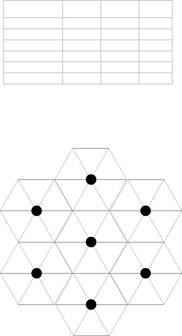
12.5.9 Multiple Access Points Clusters
When deploying multiple AP clusters in a dense area, consider aligning the clusters as
shown in Figure 32. However, this is only a recommendation. An installation may dictate
a different pattern of channel assignments.
A
B
C
A
B
C
A
B
C
A
B
C
A
B
C
A
B
C
A
B
C
A
B
C
A
B
C
A
B
C
A
B
C
A
B
C
A
B
C
A
B
C
Figure 32: Example layout of 7 Access Point clusters
12.6 SELECTING SITES FOR NETWORK ELEMENTS
The Canopy APs must be positioned
Release 8 Planning Guide
March 200 Through Software Release 6.
Issue 2, November 2007 Draft 5 for Regulatory Review 143
◦ with hardware that the wind and ambient vibrations cannot flex or move.
◦ where a tower or rooftop is available or can be erected.
◦ where a grounding system is available.
◦ with lightning arrestors to transport lightning strikes away from equipment.
◦ at a proper height:
− higher than the tallest points of objects immediately around them (such as
trees, buildings, and tower legs).
− at least 2 feet (0.6 meters) below the tallest point on the tower, pole, or roof
(for lightning protection).
◦ away from high-RF energy sites (such as AM or FM stations, high-powered
antennas, and live AM radio towers).
◦ in line-of-sight paths
− to the SMs and BH.
− that will not be obstructed by trees as they grow or structures that are later
built.
NOTE:
Visual line of sight does not guarantee radio line of sight.
12.6.1 Resources for Maps and Topographic Images
Mapping software is available from sources such as the following:
◦ http://www.microsoft.com/streets/default.asp
− Microsoft Streets & Trips (with Pocket Streets)
◦ http://www.delorme.com/software.htm
− DeLorme Street Atlas USA
− DeLorme Street Atlas USA Plus
− DeLorme Street Atlas Handheld
Topographic maps are available from sources such as the following:
◦ http://www.delorme.com/software.htm
− DeLorme Topo USA
− DeLorme 3-D TopoQuads
◦ http://www.usgstopomaps.com
− Timely Discount Topos, Inc. authorized maps
Topographic maps with waypoints are available from sources such as the following:
◦ http://www.topografix.com
− TopoGrafix EasyGPS
− TopoGrafix Panterra
Release 8 Planning Guide
March 200 Through Software Release 6.
Issue 2, November 2007 Draft 5 for Regulatory Review 144
− TopoGrafix ExpertGPS
Topographic images are available from sources such as the following:
◦ http://www.keyhole.com/body.php?h=products&t=keyholePro
− keyhole PRO
◦ http://www.digitalglobe.com
− various imagery
12.6.2 Surveying Sites
Factors to survey at potential sites include
◦ what pre-existing wireless equipment exists at the site. (Perform spectrum
analysis.)
◦ whether available mounting positions exist near the lowest elevation that satisfies
line of site, coverage, and other link criteria.
◦ whether you will always have the right to decide who climbs the tower to install
and maintain your equipment, and whether that person or company can climb at
any hour of any day.
◦ whether you will have collaborative rights and veto power to prevent interference
to your equipment from wireless equipment that is installed at the site in the
future.
◦ whether a pre-existing grounding system (path to Protective Earth
) exists, and
what is required to establish a path to it.
◦ who is permitted to run any indoor lengths of cable.
12.6.3 Assuring the Essentials
In the 2.4-, 5.2-, 5.4-, and 5.7-GHz frequency band ranges, an unobstructed line of sight
(LOS) must exist and be maintainable between the radios that are involved in each link.
Line of Sight (LOS) Link
In these ranges, a line of sight link is both
◦ an unobstructed straight line from radio to radio.
◦ an unobstructed zone surrounding that straight line.
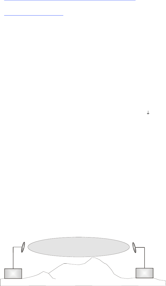
Fresnel Zone Clearance
An unobstructed line of sight is important, but is not the only determinant of adequate
placement. Even where the path has a clear line of sight, obstructions such as terrain,
vegetation, metal roofs, or cars may penetrate the Fresnel zone and cause signal loss.
Figure 33 illustrates an ideal Fresnel zone.
Transmitter
or Amplifier receiver
transmitter
Fresnel zone

Release 8 Planning Guide
March 200 Through Software Release 6.
Issue 2, November 2007 Draft 5 for Regulatory Review 145
Figure 33: Fresnel zone
FresnelZoneCalcPage.xls calculates the Fresnel zone clearance that is required between
the visual line of sight and the top of an obstruction that would protrude into the link path.
Non-Line of Sight (NLOS) Link
The Canopy 900-MHz modules have a line of sight (LOS) range of 40 miles (more than
64 km) and greater non-line of sight (NLOS) range than Canopy modules of other
frequency bands. NLOS range depends on RF considerations such as foliage,
topography, obstructions.
12.6.4 Finding the Expected Coverage Area
The transmitted beam in the vertical dimension covers more area beyond than in front of
the beam center. BeamwidthRadiiCalcPage.xls calculates the radii of the beam coverage
area.
12.6.5 Clearing the Radio Horizon
Because the surface of the earth is curved, higher module elevations are required for
greater link distances. This effect can be critical to link connectivity in link spans that are
greater than 8 miles (12 km). AntennaElevationCalcPage.xls calculates the minimum
antenna elevation for these cases, presuming no landscape elevation difference from one
end of the link to the other.
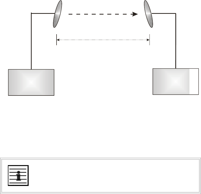
12.6.6 Calculating the Aim Angles
The appropriate angle of AP downward tilt is derived from both the distance between
transmitter and receiver and the difference in their elevations. DowntiltCalcPage.xls
calculates this angle.
The proper angle of tilt can be calculated as a factor of both the difference in elevation
and the distance that the link spans. Even in this case, a plumb line and a protractor can
be helpful to ensure the proper tilt. This tilt is typically minimal.
The number of degrees to offset (from vertical) the mounting hardware leg of the support
tube is equal to the angle of elevation from the lower module to the higher module (<B in
the example provided in Figure 34).
LEGEND
b Angle of elevation.
B Vertical difference in elevation.
A Horizontal distance between modules.
Figure 34: Variables for calculating angle of elevation (and depression)

Release 8 Planning Guide
March 200 Through Software Release 6.
Issue 2, November 2007 Draft 5 for Regulatory Review 146
Calculating the Angle of Elevation
To use metric units to find the angle of elevation, use the following formula:
tan b =
B
1000A
where
B is expressed in meters
A is expressed in kilometers.
To use English standard units to find the angle of elevation, use the following formula:
tan b =
B
5280A
where
B is expressed in feet
A is expressed in miles.
The angle of depression from the higher module is identical to the angle of elevation from
the lower module.
12.7 COLLOCATING CANOPY MODULES
A BH and an AP or AP cluster on the same tower require a CMM. The CMM properly
synchronizes the transmit start times of all Canopy modules to prevent interference and
desensing of the modules. At closer distances without sync from a CMM, the frame
structures cause self interference.
Furthermore, a BH and an AP on the same tower require that the effects of their differing
receive start times be mitigated by either
◦ 100 vertical feet (30 meters) or more and as much spectral separation as
possible within the same frequency band range.
◦ the use of the frame calculator to tune the Downlink Data parameter in each,
so that the receive start time in each is the same. See Using the Frame
Calculator Tool (All) on Page 438.
Canopy APs and a BHS can be collocated at the same site only if they operate in
different frequency band ranges.
Where a single BH air link is insufficient to cover the distance from an AP cluster to your
point of presence (POP), you can deploy two BHSs, connected to one another by
Ethernet, on a tower that is between a BHM collocated with the AP cluster and another
BHM collocated with the POP. This deployment is illustrated in Figure 35.
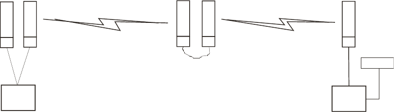
Release 8 Planning Guide
March 200 Through Software Release 6.
Issue 2, November 2007 Draft 5 for Regulatory Review 147
CMM
BH
-M-
AP BH
-S-
CMM
BH
-S-
CMM
BH
-M-
CMM
POP
Figure 35: Double-hop backhaul links
However, the BHSs can be collocated at the same site only if one is on a different
frequency band range from that of the other or one of the following conditions applies:
◦ They are vertically separated on a structure by at least 100 feet (30 m).
◦ They are vertically separated on a structure by less distance, but either
− an RF shield isolates them from each other.
− the uplink and downlink data parameters and control channels match (the
Downlink Data parameter is set to 50%).
The constraints for collocated modules in the same frequency band range are to avoid
self-interference that would occur between them. Specifically, unless the uplink and
downlink data percentages match, intervals exist when one is transmitting while the other
is receiving, such that the receiving module cannot receive the signal from the far end.
The interference is less a problem during low throughput periods and intolerable during
high. Typically, during low throughput periods, sufficient time exists for the far end to
retransmit packets lost because of interference from the collocated module.
12.8 DEPLOYING A REMOTE AP
In cases where the subscriber population is widely distributed, or conditions such as
geography restrict network deployment, you can add a Remote AP to
◦ provide high-throughput service to near LoS business subscribers.
◦ reach around obstructions or penetrate foliage with non-LoS throughput.
◦ reach new, especially widely distributed, residential subscribers with broadband
service.
◦ pass sync to an additional RF hop.
In the remote AP configuration, a Canopy AP is collocated with a Canopy SM. The
remote AP distributes the signal over the last mile to SMs that are logically behind the
collocated SM. A remote AP deployment is illustrated in Figure 36.
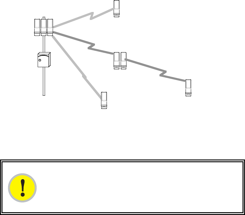
Release 8 Planning Guide
March 200 Through Software Release 6.
Issue 2, November 2007 Draft 5 for Regulatory Review 148
C A N O P Y
C A N O P Y
C A N O P Y
C A N O P Y
Canopy
SM
Canopy
SM with
Remote AP
Canopy
SM
C A N O P Y
AP
C A N O P Y C A N O P Y C A N O P Y
C A N O P Y
Canopy
SM
C A N O P YC A N O P YC A N O P YC A N O P Y
C A N O P YC A N O P Y
C A N O P YC A N O P Y
C A N O P YC A N O P Y
Canopy
SM
Canopy
SM with
Remote AP
Canopy
SM
C A N O P YC A N O P Y
AP
C A N O P Y C A N O P Y C A N O P YC A N O P YC A N O P Y C A N O P YC A N O P Y C A N O P YC A N O P Y
C A N O P YC A N O P Y
Canopy
SM
Figure 36: Remote AP deployment
The collocated SM receives data in one frequency band, and the remote AP must
redistribute the data in a different frequency band. Base your selection of frequency band
ranges on regulatory restrictions, environmental conditions, and throughput requirements.
IMPORTANT!
Each relay hop (additional daisy-chained remote AP) adds latency to the link as
follows:
◦ approximately 6 msec where hardware scheduling is enabled.
◦ approximately 15 msec where software scheduling is enabled.
12.8.1 Remote AP Performance
The performance of a remote AP is identical to the AP performance in cluster.
Throughputs, ranges, and patch antenna coverage are identical. Canopy Advantage and
Canopy modules can be deployed in tandem in the same sector to meet customer
bandwidth demands.
As with all equipment operating in the unlicensed spectrum, Motorola strongly
recommends that you perform site surveys before you add network elements. These will
indicate that spectrum is available in the area where you want to grow. Keep in mind that
◦ non-LoS ranges heavily depend on environmental conditions.
◦ in most regions, not all frequencies are available.
◦ your deployments must be consistent with local regulatory restrictions.
12.8.2 Example Use Case for RF Obstructions
A remote AP can be used to provide last-mile access to a community where RF
obstructions prevent SMs from communicating with the higher-level AP in cluster. For
example, you may be able to use 900 MHz for the last mile between a remote AP and the
outlying SMs where these subscribers cannot form good links to a higher-level 2.4-GHz
AP. In this case, the short range of the 900-MHz remote AP is sufficient, and the ability of
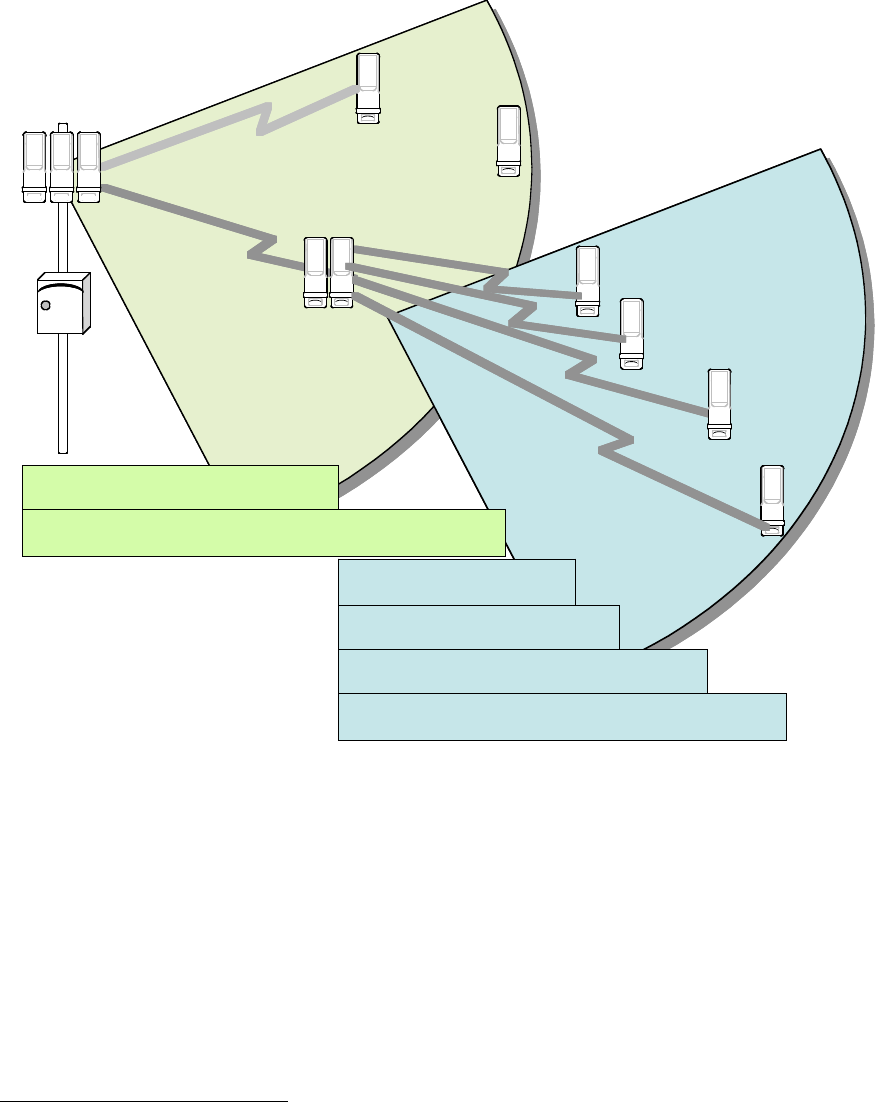
Release 8 Planning Guide
March 200 Through Software Release 6.
Issue 2, November 2007 Draft 5 for Regulatory Review 149
the 900-MHz wavelength to be effective around foliage at short range solves the foliage
penetration problem.
An example of this use case is shown in Figure 37.
C A N O P Y
C A N O P Y
2.4 GHz SM
2.4 GHz SM
with
Remote 900 MHz AP
C A N O P Y
2.4 GHz AP
C A N O P Y
C A N O P Y
C A N O P Y
C A N O P Y
900 MHz SM
4 Mbps Maximum Throughput
NLoS
Range ~2 miles
14 Mbps Maximum Aggregate Throughput
LoS
Range 2.5 miles
7 Mbps Maximum Aggregate Throughput
LoS
Range 5 miles
C A N O P Y
C A N O P Y
C A N O P Y
900 MHz SM
2 Mbps Maximum Throughput
NLoS
Range ~4 miles
C A N O P Y
900 MHz SM
4 Mbps Maximum Throughput
LoS
Range 20 miles
C A N O P Y
900 MHz SM
2 Mbps Maximum Throughput
LoS
Range 40 miles
C A N O P Y C A N O P Y C A N O P Y C A N O P Y
C A N O P Y C A N O P Y
2.4 GHz SM
2.4 GHz SM
with
Remote 900 MHz AP
C A N O P Y C A N O P Y
2.4 GHz AP
C A N O P Y
C A N O P Y
C A N O P Y
C A N O P Y C A N O P Y
C A N O P Y C A N O P Y
C A N O P Y C A N O P Y
C A N O P Y C A N O P Y
900 MHz SM
4 Mbps Maximum Throughput
NLoS
Range ~2 miles
14 Mbps Maximum Aggregate Throughput
LoS
Range 2.5 miles
7 Mbps Maximum Aggregate Throughput
LoS
Range 5 miles
C A N O P Y C A N O P Y
C A N O P Y C A N O P Y
C A N O P Y C A N O P Y
900 MHz SM
2 Mbps Maximum Throughput
NLoS
Range ~4 miles
C A N O P Y C A N O P Y
900 MHz SM
4 Mbps Maximum Throughput
LoS
Range 20 miles
C A N O P Y C A N O P Y
900 MHz SM
2 Mbps Maximum Throughput
LoS
Range 40 miles
Figure 37: Example 900-MHz remote AP behind 2.4-GHz SM
The 2.4 GHz modules provide a sustained aggregate throughput of up to 14 Mbps to the
sector. One of the SMs in the sector is wired to a 900-MHz remote AP, which provides
NLoS sustained aggregate throughput4 of
◦ 4 Mbps to 900-MHz SMs up to 2 miles away in the sector.
◦ 2 Mbps to 900-MHz SMs between 2 and 4 miles away in the sector.
12.8.3 Example Use Case for Passing Sync
All Canopy radios support the remote AP functionality. The BHS and the SM can reliably
pass the sync pulse, and the BHM and AP can reliably receive it. Examples of passing
4 NLoS ranges depend on environmental conditions. Your results may vary from these.
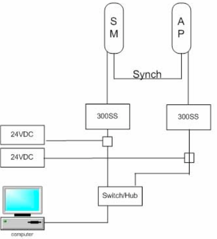
Release 8 Planning Guide
March 200 Through Software Release 6.
Issue 2, November 2007 Draft 5 for Regulatory Review 150
sync over cable are shown under Passing Sync in an Additional Hop on Page 95. The
sync cable is described under Cables on Page 57.
The sync is passed in a cable that connects Pins 1 and 6 of the RJ-11 timing ports of the
two modules. When you connect modules in this way, you must also adjust configuration
parameters to ensure that
◦ the AP is set to properly receive sync.
◦ the SM will not propagate sync to the AP if the SM itself ceases to receive sync.
Perform Procedure 35: Extending network sync on Page 367.
12.8.4 Physical Connections Involving the Remote AP
The SM to which you wire a remote AP can be either an SM that serves a customer or an
SM that simply serves as a relay. Where the SM serves a customer, wire the remote AP
to the SM as shown in Figure 38.
Figure 38: Remote AP wired to SM that also serves a customer
Where the SM simply serves as a relay, you must use a straight-through RJ-45
female-to-female coupler, and wire the SM to the remote AP as shown in Figure 39.
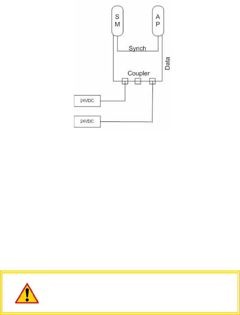
Release 8 Planning Guide
March 200 Through Software Release 6.
Issue 2, November 2007 Draft 5 for Regulatory Review 151
Figure 39: Remote AP wired to SM that serves as a relay
12.9 DIAGRAMMING NETWORK LAYOUTS
12.9.1 Accounting for Link Ranges and Data Handling Requirements
For aggregate throughput correlation to link distance in both point-to-multipoint and
point-to-point links, see
◦ Link Performance and Encryption Comparisons on Page 61.
◦ all regulations that apply in your region and nation(s).
12.9.2 Avoiding Self Interference
For 5.2-, 5.4-, and 5.7-GHz modules, 20-MHz wide channels are centered every 5 MHz.
For 2.4-GHz modules, 20-MHz wide channels are centered every 2.5 MHz. For 5.4-GHz
OFDM modules, 10-MHz wide channels can be centered every 0.5 MHz. This allows you
to customize the channel layout for interoperability where other Canopy equipment is
collocated, as well as select channels with the least background interference level.
CAUTION!
Regardless of whether 2.4-, 5.2-, 5.4-, or 5.7-GHz modules are deployed,
channel separation between modules should be at least 20 MHz for 1X
operation or 25 MHz for 2X.
Physical Proximity
A BH and an AP on the same tower require a CMM. The CMM properly synchronizes the
transmit start times of all Canopy modules to prevent interference and desensing of the
modules. At closer distances without sync from a CMM, the frame structures cause self
interference.

Release 8 Planning Guide
March 200 Through Software Release 6.
Issue 2, November 2007 Draft 5 for Regulatory Review 152
Furthermore, a BH and an AP on the same tower require that the effects of their differing
receive start times be mitigated by either
◦ 100 vertical feet (30 meters) or more and as much spectral separation as
possible within the same frequency band range.
◦ the use of the frame calculator to tune the Downlink Data % parameter in each,
so that the receive start time in each is the same. See Using the Frame
Calculator Tool (All) on Page 438.
Spectrum Analysis (Not available on Canopy OFDM modules)
You can use an SM or BHS as a spectrum analyzer. See Mapping RF Neighbor
Frequencies on Page 131. Through a toggle of the Device Type parameter, you can
temporarily transform an AP into an SM to use it as a spectrum analyzer.
Power Reduction to Mitigate Interference
Where any module (SM, AP, BH timing master, or BH timing slave) is close enough to
another module that self-interference is possible, you can set the SM to operate at less
than full power. To do so, perform the following steps.
CAUTION!
Too low a setting of the Transmitter Output Power parameter can cause a link
to a distant module to drop. A link that drops for this reason requires Ethernet
access to the GUI to re-establish the link.
Procedure 3: Reducing transmitter output power
1. Access the Radio tab of the module.
2. In the Transmitter Output Power parameter, reduce the setting.
3. Click Save Changes.
4. Click Reboot.
5. Access the Session Status tab in the Home web page of the SM.
6. Assess whether the link achieves good Power Level and Jitter values.
NOTE: The received Power Level is shown in dBm and should be maximized.
Jitter should be minimized. However, better/lower jitter should be favored over
better/higher dBm. For historical reasons, RSSI is also shown and is the unitless
measure of power. The best practice is to use Power Level and ignore RSSI,
which implies more accuracy and precision than is inherent in its measurement.
7. Access the Link Capacity Test tab in the Tools web page of the module.
8. Assess whether the desired links for this module achieve
◦ uplink efficiency greater than 90%.
◦ downlink efficiency greater than 90%.
9. If the desired links fail to achieve any of the above measurement thresholds, then
a. access the module by direct Ethernet connection.
b. access the Radio tab in the Configuration web page of the module.
c. in the Transmitter Output Power parameter, increase the setting.
Release 8 Planning Guide
March 200 Through Software Release 6.
Issue 2, November 2007 Draft 5 for Regulatory Review 153
d. click Save Changes.
e. click Reboot.
=========================== end of procedure ======================
12.9.3 Avoiding Other Interference
Where signal strength cannot dominate noise levels, the network experiences
◦ bit error corrections.
◦ packet errors and retransmissions.
◦ lower throughput (because bandwidth is consumed by retransmissions) and high
latency (due to resends).
Be especially cognitive of these symptoms for 900-MHz links. Where you see these
symptoms, attempt the following remedies:
◦ Adjust the position of the SM.
◦ Deploy a band-pass filter at the AP.
◦ Consider adding a remote AP closer to the affected SMs. (See Deploying a
Remote AP on Page 147.)
Certain other actions, which may seem to be potential remedies, do not resolve high
noise level problems:
◦ Do not deploy an omnidirectional antenna.
◦ Do not set the antenna gain above the regulated level.
◦ Do not deploy a band-pass filter in the expectation that this can mitigate co-
channel interference.

Release 8 Planning Guide
March 200 Through Software Release 6.
Issue 2, November 2007 Draft 5 for Regulatory Review 155
13 ENGINEERING YOUR IP COMMUNICATIONS
13.1 UNDERSTANDING ADDRESSES
A basic understanding of Internet Protocol (IP) address and subnet mask concepts is
required for engineering your IP network.
13.1.1 IP Address
The IP address is a 32-bit binary number that has four parts (octets). This set of four
octets has two segments, depending on the class of IP address. The first segment
identifies the network. The second identifies the hosts or devices on the network. The
subnet mask marks a boundary between these two sub-addresses.
13.2 DYNAMIC OR STATIC ADDRESSING
For any computer to communicate with a Canopy module, the computer must be
configured to either
◦ use DHCP (Dynamic Host Configuration Protocol). In this case, when not
connected to the network, the computer derives an IP address on the 169.254
network within two minutes.
◦ have an assigned static IP address (for example, 169.254.1.5) on the 169.254
network.
IMPORTANT!
If an IP address that is set in the module is not the 169.254.x.x network address,
then the network operator must assign the computer a static IP address in the
same subnet.
13.2.1 When a DHCP Server is Not Found
To operate on a network, a computer requires an IP address, a subnet mask, and
possibly a gateway address. Either a DHCP server automatically assigns this
configuration information to a computer on a network or an operator must input these
items.
When a computer is brought on line and a DHCP server is not accessible (such as when
the server is down or the computer is not plugged into the network), Microsoft and Apple
operating systems default to an IP address of 169.254.x.x and a subnet mask of
255.255.0.0 (169.254/16, where /16 indicates that the first 16 bits of the address range
are identical among all members of the subnet).
Release 8 Planning Guide
March 200 Through Software Release 6.
Issue 2, November 2007 Draft 5 for Regulatory Review 156
13.3 NETWORK ADDRESS TRANSLATION (NAT)
13.3.1 NAT, DHCP Server, DHCP Client, and DMZ in SM
The Canopy system provides NAT (network address translation) for SMs in the following
combinations of NAT and DHCP (Dynamic Host Configuration Protocol):
◦ NAT Disabled (as in earlier releases)
◦ NAT with DHCP Client and DHCP Server
◦ NAT with DHCP Client
◦ NAT with DHCP Server
◦ NAT without DHCP
NAT
NAT isolates devices connected to the Ethernet/wired side of an SM from being seen
directly from the wireless side of the SM. With NAT enabled, the SM has an IP address
for transport traffic (separate from its address for management), terminates transport
traffic, and allows you to assign a range of IP addresses to devices that are connected
to the Ethernet/wired side of the SM.
In the Canopy system, NAT supports many protocols, including HTTP, ICMP (Internet
Control Message Protocols), and FTP (File Transfer Protocol). For virtual private network
(VPN) implementation, L2TP over IPSec (Level 2 Tunneling Protocol over IP Security) is
supported, but PPTP (Point to Point Tunneling Protocol) is not supported. See NAT and
VPNs on Page 161.
DHCP
DHCP enables a device to be assigned a new IP address and TCP/IP parameters,
including a default gateway, whenever the device reboots. Thus DHCP reduces
configuration time, conserves IP addresses, and allows modules to be moved to a
different network within the Canopy system.
In conjunction with the NAT features, each SM provides
◦ a DHCP server that assigns IP addresses to computers connected to the SM by
Ethernet protocol.
◦ a DHCP client that receives an IP address for the SM from a network DHCP
server.
DMZ
In conjunction with the NAT features, a DMZ (demilitarized zone) allows the assignment
of one IP address behind the SM for a device to logically exist outside the firewall and
receive network traffic. The first three octets of this IP address must be identical to the
first three octets of the NAT private IP address.
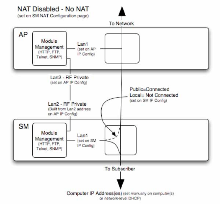
Release 8 Planning Guide
March 200 Through Software Release 6.
Issue 2, November 2007 Draft 5 for Regulatory Review 157
NAT Disabled
The NAT Disabled implementation is illustrated in Figure 40.
Figure 40: NAT Disabled implementation
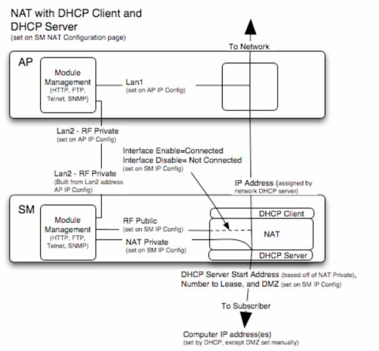
Release 8 Planning Guide
March 200 Through Software Release 6.
Issue 2, November 2007 Draft 5 for Regulatory Review 158
NAT with DHCP Client and DHCP Server
The NAT with DHCP Client and DHCP Server implementation is illustrated in Figure 41.
Figure 41: NAT with DHCP Client and DHCP Server implementation
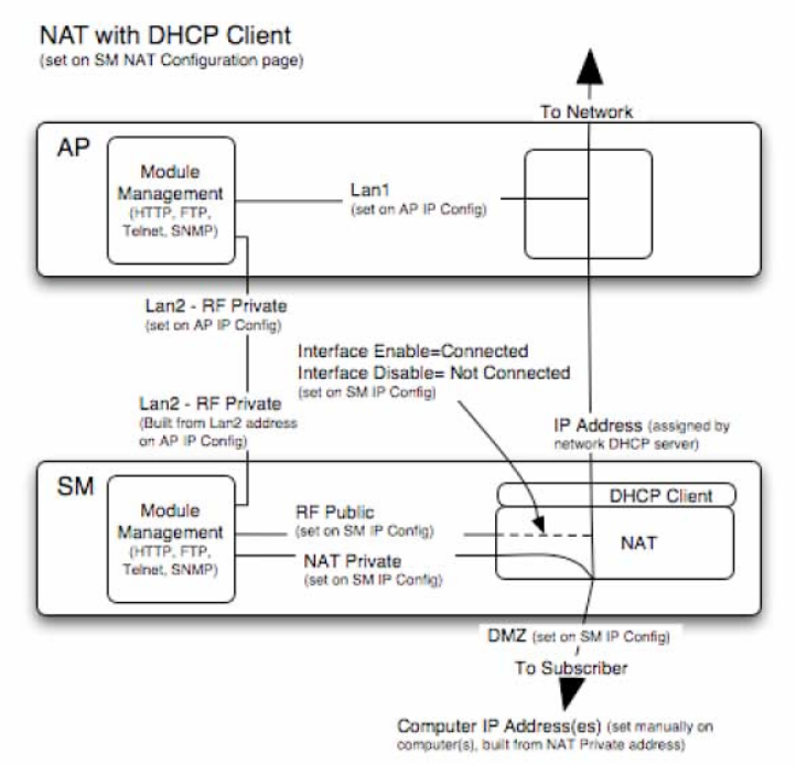
Release 8 Planning Guide
March 200 Through Software Release 6.
Issue 2, November 2007 Draft 5 for Regulatory Review 159
NAT with DHCP Client
The NAT with DHCP Client implementation is illustrated in Figure 42.
Figure 42: NAT with DHCP Client implementation
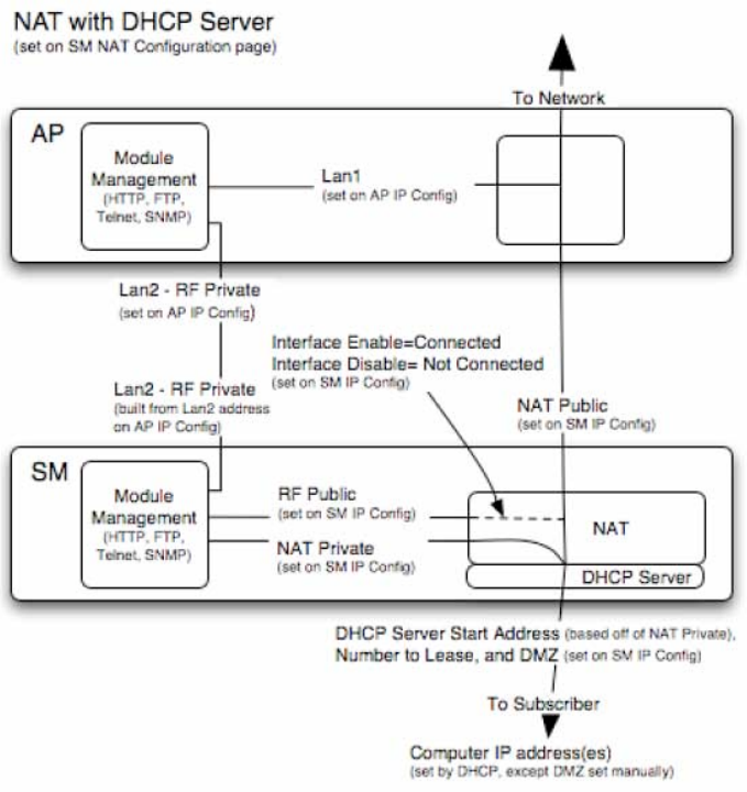
Release 8 Planning Guide
March 200 Through Software Release 6.
Issue 2, November 2007 Draft 5 for Regulatory Review 160
NAT with DHCP Server
The NAT with DHCP Server implementation is illustrated in Figure 43.
Figure 43: NAT with DHCP Server implementation
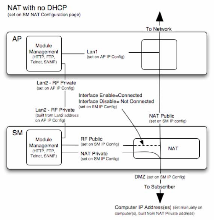
Release 8 Planning Guide
March 200 Through Software Release 6.
Issue 2, November 2007 Draft 5 for Regulatory Review 161
NAT without DHCP
The NAT without DHCP implementation is illustrated in Figure 44.
Figure 44: NAT without DHCP implementation
13.3.2 NAT and VPNs
VPN technology provides the benefits of a private network during communication over a
public network. One typical use of a VPN is to connect remote employees, who are at
home or in a different city, to their corporate network over the public Internet. Any of
several VPN implementation schemes is possible. By design, NAT translates or changes
addresses, and thus interferes with a VPN that is not specifically supported by a given
NAT implementation.
With NAT enabled, SMs support L2TP over IPSec (Level 2 Tunneling Protocol over IP
Security) VPNs, but do not support PPTP (Point to Point Tunneling Protocol) VPNs.
With NAT disabled, SMs support all types of VPNs.
13.4 DEVELOPING AN IP ADDRESSING SCHEME
Canopy network elements are accessed through IP Version 4 (IPv4) addressing.
A proper IP addressing method is critical to the operation and security of a Canopy
network.
Release 8 Planning Guide
March 200 Through Software Release 6.
Issue 2, November 2007 Draft 5 for Regulatory Review 162
Each Canopy module requires an IP address on the network. This IP address is for only
management purposes. For security, you should either
◦ assign an unroutable IP address.
◦ assign a routable IP address only if a firewall is present to protect the module.
You will assign IP addresses to computers and network components by either static or
dynamic IP addressing. You will also assign the appropriate subnet mask and network
gateway to each module.
13.4.1 Address Resolution Protocol
As previously stated, the MAC address identifies a Canopy module in
◦ communications between modules.
◦ the data that modules store about each other.
◦ the data that BAM or Prizm applies to manage authentication and bandwidth.
The IP address is essential for data delivery through a router interface. Address
Resolution Protocol (ARP) correlates MAC addresses to IP addresses.
For communications to outside the network segment, ARP reads the network gateway
address of the router and translates it into the MAC address of the router. Then the
communication is sent to MAC address (physical network interface card) of the router.
For each router between the sending module and the destination, this sequence applies.
The ARP correlation is stored until the ARP cache times out.
13.4.2 Allocating Subnets
The subnet mask is a 32-bit binary number that filters the IP address. Where a subnet
mask contains a bit set to 1, the corresponding bit in the IP address is part of the network
address.
Example IP Address and Subnet Mask
In Figure 45, the first 16 bits of the 32-bit IP address identify the network:
Octet 1
Octet 2
Octet 3
Octet 4
IP address 169.254.1.1
10101001
11111110
00000001
00000001
Subnet mask 255.255.0.0
11111111
11111111
00000000
00000000
Figure 45: Example of IP address in Class B subnet
In this example, the network address is 169.254, and 216 (65,536) hosts are addressable.
13.4.3 Selecting Non-routable IP Addresses
The factory default assignments for Canopy network elements are
◦ unique MAC address
◦ IP address of 169.254.1.1, except for an OFDM series BHM, whose IP address
is 169.254.1.2 by default
◦ subnet mask of 255.255.0.0
Release 8 Planning Guide
March 200 Through Software Release 6.
Issue 2, November 2007 Draft 5 for Regulatory Review 163
◦ network gateway address of 169.254.0.0
For each Canopy radio and CMMmicro, assign an IP address that is both consistent
with the IP addressing plan for your network and cannot be accessed from the Internet.
IP addresses within the following ranges are not routable from the Internet, regardless of
whether a firewall is configured:
◦ 10.0.0.0 – 10.255.255.255
◦ 172.16.0.0 – 172.31.255.255
◦ 192.168.0.0 – 192.168.255.255
You can also assign a subnet mask and network gateway for each CMMmicro.
Release 8 Planning Guide
March 200 Through Software Release 6.
Issue 2, November 2007 Draft 5 for Regulatory Review 165
14 ENGINEERING VLANS
Canopy radios support VLAN functionality as defined in the 802.1Q (Virtual LANs)
specification, except for the following aspects of that specification:
◦ the following protocols:
− Generic Attribute Registration Protocol (GARP) GARV
− Spanning Tree Protocol (STP)
− Multiple Spanning Tree Protocol (MSTP)
− GARP Multicast Registration Protocol (GMRP)
◦ priority encoding (802.1P) before Release 7.0
◦ embedded source routing (ERIF) in the 802.1Q header
◦ multicast pruning
◦ flooding unknown unicast frames in the downlink
As an additional exception, the Canopy AP does not flood downward the unknown
unicast frames to the Canopy SM.
A VLAN configuration in Layer 2 establishes a logical group within the network. Each
computer in the VLAN, regardless of initial or eventual physical location, has access to
the same data. For the network operator, this provides flexibility in network segmentation,
simpler management, and enhanced security.
14.1 SM MEMBERSHIP IN VLANS
With the supported VLAN functionality, Canopy radios determine bridge forwarding on
the basis of not only the destination MAC address, but also the VLAN ID of the
destination. This provides flexibility in how SMs are used:
◦ Each SM can be a member in its own VLAN.
◦ Each SM can be in its own broadcast domain, such that only the radios that are
members of the VLAN can see broadcast and multicast traffic to and from the
SM.
◦ The network operator can define a work group of SMs, regardless of the AP(s)
to which they register.
Canopy point-to-multipoint modules provide the VLAN frame filters that are described in
Table 36.

Release 8 Planning Guide
March 200 Through Software Release 6.
Issue 2, November 2007 Draft 5 for Regulatory Review 166
Table 36: VLAN filters in point-to-multipoint modules
then a frame is discarded if…
entering the bridge/
NAT switch through…
Where VLAN is active,
if this parameter value
is selected …
Ethernet…
TCP/IP…
because of this VLAN
filter in the Canopy
software:
any combination of VLAN
parameter settings
with a VID not in the
membership table
Ingress
any combination of VLAN
parameter settings
with a VID not in the
membership table
Local Ingress
Allow Frame Types:
Tagged Frames Only
with no 802.1Q tag
Only Tagged
Allow Frame Types:
Untagged Frames Only
with an 802.1Q tag,
regardless of VID
Only Untagged
Local SM Management:
Disable in the SM, or
All Local SM Management:
Disable in the AP
with an 802.1Q tag
and a VID in the
membership table
Local SM Management
leaving the bridge/
NAT switch through…
Ethernet…
TCP/IP…
any combination of VLAN
parameter settings
with a VID not in the
membership table
Egress
any combination of VLAN
parameter settings
with a VID not in the
membership table
Local Egress
14.2 PRIORITY ON VLANS (802.1p)
Canopy radios can prioritize traffic based on the eight priorities described in the IEEE
802.1p specification. When the high-priority channel is enabled on an SM, regardless of
whether VLAN is enabled on the AP for the sector, packets received with a priority of
4 through 7 in the 802.1p field are forwarded onto the high-priority channel.
VLAN settings in a Canopy module can also cause the module to convert received non-
VLAN packets into VLAN packets. In this case, the 802.1p priority in packets leaving the
module is set to the priority established by the DiffServ configuration.
If you enable VLAN, immediately monitor traffic to ensure that the results are as desired.
For example, high-priority traffic may block low-priority.
For more information on the Canopy high priority channel, see High-priority Bandwidth on
Page 86.

Release 8 Installation and Configuration Guide
Issue 2, November 2007 Draft 5 for Regulatory Review 167
I
I
IN
N
NS
S
ST
T
TA
A
AL
L
LL
L
LA
A
AT
T
TI
I
IO
O
ON
N
N
A
A
AN
N
ND
D
D
C
C
CO
O
ON
N
NF
F
FI
I
IG
G
GU
U
UR
R
RA
A
AT
T
TI
I
IO
O
ON
N
N
G
G
GU
U
UI
I
ID
D
DE
E
E
Release 8 Installation and Configuration Guide
Issue 2, November 2007 Draft 5 for Regulatory Review 169
15 AVOIDING HAZARDS
Use simple precautions to protect staff and equipment. Hazards include exposure to RF
waves, lightning strikes, and power surges. This section specifically recommends actions
to abate these hazards.
15.1 EXPOSURE SEPARATION DISTANCES
To protect from overexposure to RF energy, install Canopy radios so as to provide and
maintain the minimum separation distances from all persons shown in Table 37.
Table 37: Exposure separation distances
Module Type
Separation Distance from Persons
Canopy Module, FSK or OFDM
At least 20 cm (approx 8 in)
Canopy Module with Reflector Dish
At least 1.5 m (approx 60 in or 5 ft)
Canopy Module with LENS
At least 0.5 m (approx 20 in)
Antenna of connectorized 5.7 GHz AP
At least 30 cm (approx 12 in)
Antenna of connectorized or integrated 900
MHz module
At least 60 sm (24 in)
Indoor 900 MHz SM
At least 10 cm (4 in)
Section 15.1.1 and Table 38 give details and discussion of the associated calculations.
15.1.1 Details of Exposure Separation Distances Calculations and Power
Compliance Margins
Limits and guidelines for RF exposure come from:
◦ US FCC limits for the general population. See the FCC web site at
http://www.fcc.gov, and the policies, guidelines, and requirements in Part 1 of Title 47
of the Code of Federal Regulations, as well as the guidelines and suggestions for
evaluating compliance in FCC OET Bulletin 65.
◦ Health Canada limits for the general population. See the Health Canada web site at
http://www.hc-sc.gc.ca/rpb and Safety Code 6.
◦ ICNIRP (International Commission on Non-Ionizing Radiation Protection) guidelines
for the general public. See the ICNIRP web site at http://www.icnirp.de/ and
Guidelines for Limiting Exposure to Time-Varying Electric, Magnetic, and
Electromagnetic Fields.
The applicable power density exposure limits from the documents referenced above are
◦ 6 W/m2 for RF energy in the 900-MHz frequency band in the US and Canada.
◦ 10 W/m2 for RF energy in the 2.4-, 5.2-, 5.4-, and 5.7-GHz frequency bands.
Peak power density in the far field of a radio frequency point source is calculated as
follows:

Release 8 Installation and Configuration Guide
Issue 2, November 2007 Draft 5 for Regulatory Review 170
!
S=P"G
4
#
d2
where
S = power density in W/m2
P = RMS transmit power capability of the radio, in W
G = total Tx gain as a factor, converted from dB
d = distance from point source, in m
Rearranging terms to solve for distance yields
!
d=P"G
4
#
S
Table 38 shows calculated minimum separation distances d, recommended distances
and resulting power compliance margins for each frequency band and antenna
combination.
Table 38: Calculated exposure distances and power compliance margins
Variable
Fre-
quency
Band
Antenna
P
G
S
d
(calcu-
lated)
Recom-
mended
Separation
Distance
Power
Compliance
Margin
external
0.4 W
(26 dBm)
10.0
(10 dB)
6 W/m2
23 cm
60 cm
(24 in)
7
integrated
0.25 W
(24 dBm)
15.8
(12 dB)
6 W/m2
23 cm
60 cm
(24 in)
7
900 MHz
indoor,
integrated
Simulation model used to estimate Specific
Absorption Rate (SAR) levels
10 cm
(4 in)
2
integrated
0.34 W
(25 dBm)
6.3
(8 dB)
10
W/m2
13 cm
20 cm
(8 in)
2.3
2.4 GHz
integrated
plus
reflector
0.34 W
(25 dBm)
79.4
(19 dB)
10
W/m2
46 cm
1.5 m
(5 ft)
10
integrated
0.2 W
(23 dBm)
5.0
(7 dB)
10
W/m2
9 cm
20 cm
(8 in)
5
integrated
plus
reflector
0.0032 W
(5 dBm)
316
(25 dB)
10
W/m2
9 cm
1.5 m
(5 ft)
279
5.2 GHz
integrated
plus LENS
0.025 W
(14 dBm)
40
(16 dB)
10
W/m2
9 cm
50 cm
(12 in)
31
integrated
0.2 W
(23 dBm)
5.0
(7 dB)
10
W/m2
9 cm
20 cm
(8 in)
5
integrated
plus
reflector
0.0032 W
(5 dBm)
316
(25 dB)
10
W/m2
9 cm
1.5 m
(5 ft)
279
5.4 GHz
integrated
plus LENS
0.020 W
(13 dBm)
50
(17 dB)
10
W/m2
9 cm
50 cm
(12 in)
31
5.4 GHz
OFDM
integrated
0.01 W
(10 dBm)
50
(17 db)
10
W/m2
6 cm
20 cm
(8 in)
10
Release 8 Installation and Configuration Guide
Issue 2, November 2007 Draft 5 for Regulatory Review 171
Variable
Fre-
quency
Band
Antenna
P
G
S
d
(calcu-
lated)
Recom-
mended
Separation
Distance
Power
Compliance
Margin
integrated
0.2 W
(23 dBm)
5.0
(7 dB)
10
W/m2
9 cm
20 cm
(8 in)
5
integrated
plus
reflector
0.2 W
(23 dBm)
316
(25 dB)
10
W/m2
71 cm
1.5 m
(5 ft)
4.5
5.7 GHz
Integrated
plus LENS
0.2 W
(23 dBm)
50
(17 dB)
1
W/m2
28 cm
50 cm
(12 in)
3.13
The “Recommended Distances” are chosen to give significant compliance margin in all
cases. They are also chosen so that a given item (bare module, reflector, or LENS)
always has the same distance, regardless of frequency band, to simplify following
exposure distances in the field.
These are conservative distances:
◦ They are along the beam direction (the direction of greatest energy). Exposure to the
sides and back of the module will be significantly less.
◦ They meet sustained exposure limits for the general population (not just short term
occupational exposure limits), with considerable margin.
◦ In the reflector cases, the calculated compliance distance d is greatly overestimated
because the far-field equation models the reflector as a point source and neglects the
physical dimension of the reflector.
15.2 GROUNDING CANOPY EQUIPMENT
Effective lightning protection diverts lightning current safely to ground, Protective Earth
(PE)
. It neither attracts nor prevents lightning strikes.
WARNING!
Lightning damage is not covered under the Canopy warranty. The
recommendations in Canopy guides give the installer the knowledge to
protect the installation from the harmful effects of ESD and lightning.
These recommendation must be thoroughly and correctly performed.
However, complete protection is neither implied or possible.
15.2.1 Grounding Infrastructure Equipment
To protect both your staff and your infrastructure equipment, implement lightning
protection as follows:
◦ Observe all local and national codes that apply to grounding for lightning
protection.
◦ Before you install your Canopy modules, perform the following steps:
− Engage a grounding professional if you need to do so.

Release 8 Installation and Configuration Guide
Issue 2, November 2007 Draft 5 for Regulatory Review 172
− Install lightning arrestors to transport lightning strikes away from equipment.
For example, install a lightning rod on a tower leg other than the leg to which
you mount your module.
− Connect your lightning rod to ground.
− Use a Canopy 600SS Surge Suppressor on the Ethernet cable where the
cable enters any structure. (Instructions for installing a Canopy 600SS Surge
Suppressor are provided in Procedure 28 on Page 344.)
◦ Install your modules at least 2 feet (0.6 meters) below the tallest point on the
tower, pole, or roof.
15.2.2 Grounding SMs
This section provides lightning protection guidelines for SMs to satisfy the National
Electrical Code (NEC) of the United States. The requirements of the NEC focus on the
safety aspects of electrical shock to personnel and on minimizing the risk of fire at a
dwelling. The NEC does not address the survivability of electronic products that are
exposed to lightning surges.
The statistical incidence of current levels from lightning strikes is summarized in
Table 39.
Table 39: Statistical incidence of current from lightning strikes
Percentage
of all strikes
Peak Current
(amps)
<2
>140,000
25
>35,000
>50
>20,000
>80
>8,500
At peak, more than one-half of all surges due to direct lightning strikes exceed 20,000
amps. However, only one-quarter exceed 35,000 amps, and less than two percent
exceed 140,000 amps. Thus, the recommended Surge Suppressor (300SS) provides
a degree of lightning protection to electronic devices inside a dwelling.
Summary of Grounding Recommendations
Motorola recommends that you ground each SM as follows:
◦ Extend the SM mounting bracket extend to the top of the SM or higher.
◦ Ground the SM mounting bracket via a 10-AWG (6 mm2) copper wire connected
by the most direct path either to an eight foot-deep ground rod or to the ground
bonding point of the AC power service utility entry. This provides the best
assurance that
− lightning takes the ground wire route
− the ground wire does not fuse open
− your grounding system complies with NEC 810-15.
◦ Ground the Canopy Surge Suppressor 300SS or 600SS ground lug to the same
ground bonding point as above, using at least a 10-AWG (6 mm2) copper wire.
This provides the best assurance that your grounding system complies with
NEC 810-21.

Release 8 Installation and Configuration Guide
Issue 2, November 2007 Draft 5 for Regulatory Review 173
Grounding Scheme
The proper overall antenna grounding scheme per the NEC is illustrated in Figure 128 on
Page 345. In most television antenna or dish installations, a coaxial cable connects the
outdoor electronics with the indoor electronics. To meet NEC 810-20, one typically uses
a coaxial cable feed-through block that connects the outdoor coax to the indoor coax and
also has a screw for attaching a ground wire. This effectively grounds the outer shield of
the coax. The block should be mounted on the outside of the building near the AC main
panel such that the ground wire of the block can be bonded to the primary grounding
electrode system of the structure.
For residential installs, in most cases an outdoor rated unshielded twisted pair (UTP)
cable is sufficient. To comply with the NEC, Motorola provides the antenna discharge
unit, 300SS or 600SS, for each conductor of the cable. The surge suppressor must be
◦ positioned
− outside the building.
− as near as practicable to the power service entry panel of the building and
attached to the AC main power ground electrode, or attached to a grounded
water pipe.5
− far from combustible material.
◦ grounded in accordance with NEC 810-21, with the grounding wire attached to
the screw terminal.
The metal structural elements of the antenna mast also require a separate grounding
conductor. Section 810-15 of the NEC states:
Masts and metal structures supporting antennas shall be grounded in
accordance with Section 810-21.
As shown in Figure 128 on Page 345, the Motorola recommendation for grounding the
metal structural element of the Canopy mounting bracket (SMMB1) is to route the
grounding wire from the SMMB1 down to the same ground attachment point as is used
for the 300SS discharge unit.
Use 10-AWG (6 mm2) Copper Grounding Wire
According to NEC 810-21 3(h), either a 16-AWG copper clad steel wire or a 10-AWG
copper wire may be used. This specification appears to be based on mechanical strength
considerations and not on lightning current handling capabilities.
For example, analysis shows that the two wire types are not equivalent when carrying
a lightning surge that has a 1-microsecond rise by 65-microsecond fall:
◦ The 16-AWG copper clad steel wire has a peak fusing current of 35,000 amps
and can carry 21,000 amps peak, at a temperature just below the ignition point
for paper (454° F or 234° C).
◦ The 10-AWG copper wire has a peak fusing current of 220,000 amps and can
carry 133,000 amps peak, at the same temperature.
5 It is insufficient to merely use the green wire ground in a duplex electrical outlet box for grounding
of the antenna discharge unit.

Release 8 Installation and Configuration Guide
Issue 2, November 2007 Draft 5 for Regulatory Review 174
Based on the electrical/thermal analysis of these wires, Motorola recommends 10-AWG
copper wire for all grounding conductors. Although roughly double the cost of 16-AWG
copper clad steel wire, 10-AWG copper wire handles six times the surge current from
lightning.
Shielding is not Grounding
In part, NEC 810-21 states:
A lightning arrester is not required if the lead-in conductors are enclosed in a
continuous metal shield, such as rigid or intermediate metal conduit, electrical
metallic tubing, or any metal raceway or metal-shielded cable that is effectively
grounded. A lightning discharge will take the path of lower impedance and jump
from the lead-in conductors to the metal raceway or shield rather than take the
path through the antenna coil of the receiver.
However, Motorola does not recommend relying on shielded twisted pair cable for
lightning protection for the following reasons:
◦ Braid-shielded 10Base-T cable is uncommon, if existent, and may be unsuitable
anyway.
◦ At a cost of about two-thirds more than 10-AWG copper UTP, CAT 5
100Base-TX foil-shielded twisted pair (FTP) cable provides a 24-AWG drain wire.
If this wire melts open during a lightning surge, then the current may follow the
twisted pair into the building.
More than 80 percent of all direct lightning strikes have current that exceeds
8,500 amps (see Table 39 on Page 172). A 24-AWG copper wire melts open at
8,500 amps from a surge that has a 1-microsecond by 70-microsecond
waveform. Hence, reliance on 24-AWG drain wire to comply with the intent of
NEC 810-21 is questionable.
Shielded twisted pair cable may be useful for mitigation of interference in some
circumstances, but installing surge suppressors and implementing the ground
recommendations constitute the most effective mitigation against lightning damage.
NEC Reference
NEC Article 810, Radio and Television Equipment, and associated documents and
discussions are available from http://www.neccode.com/index.php?id=homegeneral,
http://www.constructionbook.com/xq/ASP/national-electrical-code-2005/id.370/subID.746/qx/default2.htm,
and other sources.
15.3 CONFORMING TO REGULATIONS
For all electrical purposes, ensure that your network conforms to applicable country and
local codes, such as the NEC (National Electrical Code) in the US. If you are uncertain of
code requirements, engage the services of a licensed electrician.
15.4 PROTECTING CABLES AND CONNECTIONS
Cables that move in the wind can be damaged, impart vibrations to the connected device,
or both. At installation time, prevent these problems by securing all cables with cable ties,
cleats, or PVC tape.

Release 8 Installation and Configuration Guide
Issue 2, November 2007 Draft 5 for Regulatory Review 175
Over time, moisture can cause a cable connector to fail. You can prevent this problem by
◦ using cables that are filled with a dielectric gel or grease.
◦ including a drip loop where the cable approach to the module (typically a CMM2
or CMMmicro) is from above.
◦ wrapping the cable with weather-resistant tape.
On a module with an external antenna, use accepted industry practices to wrap the
connector to prevent water ingress. Although the male and female N-type connectors
form a gas-tight seal with each other, the point where the cable enters each connector
can allow water ingress and eventual corrosion. Wrapping and sealing is critical to long-
term reliability of the connection.
Possible sources of material to seal that point include
◦ the antenna manufacturer (material may have been provided in the package with
the antenna).
◦ Universal Electronics (whose web site is http://www.coaxseal.com), who markets
a weather-tight wrap named Coax-Seal.
Perform the following steps to wrap the cable.
Procedure 4: Wrapping the cable
1. Start the wrap on the cable 0.5 to 2 inches (about 1.5 to 5 cm) from the
connection.
2. Wrap the cable to a point 0.5 to 2 inches (about 1.5 to 5 cm) above the
connection.
3. Squeeze the wrap to compress and remove any trapped air.
4. Wrap premium vinyl electrical tape over the first wrap where desired for abrasion
resistance or appearance.
5. Tie the cable to minimize sway from wind.
=========================== end of procedure ======================
Release 8 Installation and Configuration Guide
Issue 2, November 2007 Draft 5 for Regulatory Review 177
16 TESTING THE COMPONENTS
The best practice is to connect all components—BHs, APs, GPS antenna, and CMM2 or
CMMmicro—in a test setting and initially configure and verify them before deploying them
to an installation. In this way, any configuration issues are worked out before going on-
site, on a tower, in the weather, where the discovery of configuration issues or marginal
hardware is more problematic and work-flow affecting.
16.1 UNPACKING COMPONENTS
When you receive Canopy products, carefully inspect all shipping boxes for signs of
damage. If you find damage, immediately notify the transportation company.
As you unpack the equipment, verify that all the components that you ordered have
arrived. Save all the packing materials to use later, as you transport the equipment to and
from installation sites.
16.2 CONFIGURING FOR TEST
You can use either of two methods to configure an AP or BHM:
◦ Use the Quick Start feature of the product. For more information on Quick Start,
see Quick Start Page of the AP on Page 185.
◦ Manually set each parameter.
After you change configuration parameters on a GUI web page:
1. Before you leave a web page, click the Save button to save the change(s).
2. After making change(s) on multiple web pages, click the Reboot button to reboot
the module and implement the change(s).
16.2.1 Configuring the Computing Device for Test
If your computer is configured for Dynamic Host Configuration Protocol (DHCP),
disconnect the computer from the network. If your computer is instead configured for
static IP addressing
◦ set the static address in the 169.254 network
◦ set the subnet mask to 255.255.0.0.
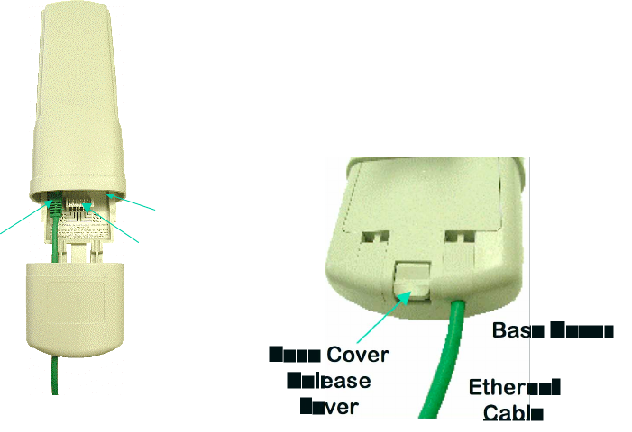
Release 8 Installation and Configuration Guide
Issue 2, November 2007 Draft 5 for Regulatory Review 178
16.2.2 Default Module Configuration
From the factory, the Canopy AP, SM, and BH are all configured to not transmit on any
frequency. This configuration ensures that you do not accidentally turn on an
unsynchronized module. Site synchronization of modules is required because
◦ Canopy modules
− cannot transmit and receive signals at the same time.
− use TDD (Time Division Duplexing) to distribute signal access of the
downlink and uplink frames.
◦ when one module transmits while an unintended module nearby receives signal,
the transmitting module may interfere with or desense the receiving module. In
this context, interference is self-interference (within the same Canopy network).
16.2.3 Component Layout
As shown in Figure 46, the base cover of the module snaps off when you depress a lever
on the back of the base cover. This exposes the Ethernet and GPS sync connectors and
diagnostic LEDs.
Figure 46: Canopy base cover, attached and detached
Ethernet
Cable
RJ45
Connector
Connection
LEDs
Base Cover
RJ11
Connector
Release 8 Installation and Configuration Guide
Issue 2, November 2007 Draft 5 for Regulatory Review 179
16.2.4 Diagnostic LEDs
The diagnostic LEDs report the following information about the status of the module.
Table 40 and Table 41 identify the LEDs in order of their left-to-right position as the cable
connections face downward.
NOTE:
The LED color helps you distinguish position of the LED. The LED color does
not indicate any status.
Table 40: LEDs in AP and BHM
Label
Color
when
Active
Status Information
Provided
Notes
LNK/5
green
Ethernet link
Continuously lit when link is present.
ACT/4
orange
Presence of data activity
on the Ethernet link
Flashes during data transfer. Frequency of flash is not a
diagnostic indication.
GPS/3
red
Pulse of sync
Continuously lit as pulse as AP receives pulse.
SES/2
green
Unused on the AP
SES is the session indicator on the CMM.
SYN/1
orange
Presence of sync
Always lit on the AP.
PWR
red
DC power
Always lit when power is correctly supplied.
Table 41: LEDs in SM and BHS
Notes
Label
Color
when
Active
Status if
Registered
Operating Mode
Aiming Mode
LNK/5
green
Ethernet link
Continuously lit when link is
present.
ACT/4
orange
Presence of data
activity on the
Ethernet link
Flashes during data transfer.
Frequency of flash is not a
diagnostic indication.
GPS/3
red
Unused
SES/2
green
Unused
SYN/1
orange
Presence of sync
If this module is not registered
to another, then these three
LEDs cycle on and off from left
to right.
These five LEDs act as a bar
graph to indicate the relative
quality of alignment. As power
level and jitter improve during
alignment, more of these
LEDs are lit.
PWR
red
DC power
Always lit when power is
correctly supplied.
Always lit when power is
correctly supplied.
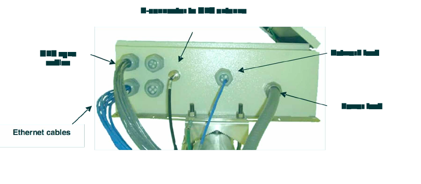
Release 8 Installation and Configuration Guide
Issue 2, November 2007 Draft 5 for Regulatory Review 180
16.2.5 CMM2 Component Layout
As shown in Figure 125 on Page 339, the CMM2 comprises four assemblies:
◦ Ethernet switch
◦ Power transformer
◦ Interconnect board
◦ GPS receiver.
Some CMM2s that were sold earlier had four openings in the bottom plate, as shown in
Figure 47. Currently available CMM2s have two additional Ethernet cable and GPS sync
cable openings to allow use of thicker, shielded cables.
Figure 47: Canopy CMM2, bottom view
16.2.6 CMMmicro Component Layout
The layout of the CMMmicro is shown in Figure 48.
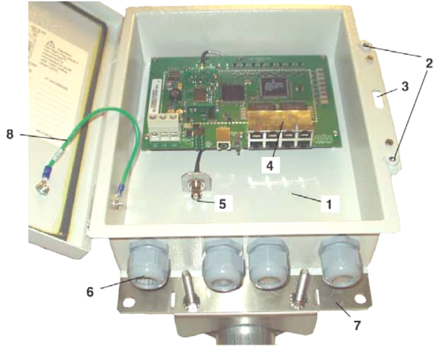
Release 8 Installation and Configuration Guide
Issue 2, November 2007 Draft 5 for Regulatory Review 181
LEGEND
1. Weatherized enclosure
2. Thumb-screw/slot-screwdriver door fasteners
3. Punch-out for padlock
4. Ethernet switch and power module
5. Female BNC connector
6. Water-tight bulkhead connectors
7. Flange for attachment (stainless steel for
grounding to tower or building) using U bolts
(provided) or other hardware such as screws, lag
bolts, or attachment straps (not provided)
8. Ground strap (for grounding door to enclosure)
9. 100-W 115/230-V AC to 24-V DC power
converter, with 10 ft (3 m) of DC power cable
(not shown)
10. 6-ft (1.8-m) AC power cord for 24 V power
converter (not shown)
Figure 48: Cluster Management Module micro
Release 8 Installation and Configuration Guide
Issue 2, November 2007 Draft 5 for Regulatory Review 182
16.2.7 Standards for Wiring
Canopy modules automatically sense whether the Ethernet cable in a connection is wired
as straight-through or crossover. You may use either straight-through or crossover cable
to connect a network interface card (NIC), hub, router, or switch to these modules. For a
straight-through cable, use the EIA/TIA-568B wire color-code standard on both ends. For
a crossover cable, use the EIA/TIA-568B wire color-code standard on one end, and the
EIA/TIA-568A wire color-code standard on the other end.
Where you use the Canopy AC wall adapter
◦ the power supply output is +24 VDC.
◦ the power input to the SM is +11.5 VDC to +30 VDC.
◦ the maximum Ethernet cable run is 328 feet (100 meters).
16.2.8 Best Practices for Cabling
The following practices are essential to the reliability and longevity of cabled connections:
◦ Use only shielded cables to resist interference.
◦ For vertical runs, provide cable support and strain relief.
◦ Include a 2-ft (0.6-m) service loop on each end of the cable to allow for thermal
expansion and contraction and to facilitate terminating the cable again when
needed.
◦ Include a drip loop to shed water so that most of the water does not reach the
connector at the device.
◦ Properly crimp all connectors.
◦ Use dielectric grease on all connectors to resist corrosion.
◦ Use only shielded connectors to resist interference and corrosion.
16.2.9 Recommended Tools for Wiring Connectors
The following tools may be needed for cabling the AP:
◦ RJ-11 crimping tool
◦ RJ-45 crimping tool
◦ electrician scissors
◦ wire cutters
◦ cable testing device.
16.2.10 Wiring Connectors
The following diagrams correlate pins to wire colors and illustrate crossovers where
applicable.
Location of Pin 1
Pin 1, relative to the lock tab on the connector of a straight-through cable is located as
shown below.
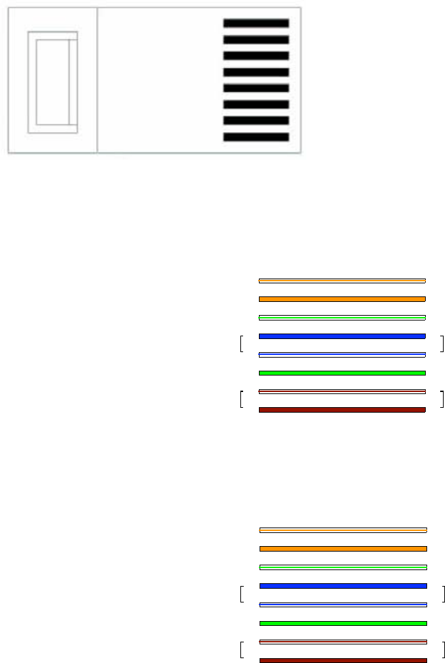
Release 8 Installation and Configuration Guide
Issue 2, November 2007 Draft 5 for Regulatory Review 183
Lock tab ↑ underneath
← Pin 1
RJ-45 Pinout for Straight-through Ethernet Cable
Pin 1 → white / orange ← Pin 1
Pin 2 → orange ← Pin 2
Pin 3 → white / green ← Pin 3
Pin 4 → blue ← Pin 4
Pin 5 → white / blue ← Pin 5
Pin 6 → green ← Pin 6
Pin 7 → white / brown ← Pin 7
Pin 8 → brown ← Pin 8
Pins 7 and 8 carry power to the
modules.
1
2
3
4
5
6
7
8
1
2
3
4
5
6
7
8
TX+
TX-
RX+
RX-
TX-
TX-
RX+
RX-
+V return
+V
Pin PinRJ-45 Straight-thru
+V return
+V
Figure 49: RJ-45 pinout for straight-through Ethernet cable
RJ-45 Pinout for Crossover Ethernet Cable
Pin 1 → white / orange ← Pin 3
Pin 2 → orange ← Pin 6
Pin 3 → white / green ← Pin 1
Pin 4 → blue ← Pin 4
Pin 5 → white / blue ← Pin 5
Pin 6 → green ← Pin 2
Pin 7 → white / brown ← Pin 7
Pin 8 → brown ← Pin 8
Pins 7 and 8 carry power to the modules.
7
8
TX+
TX-
RX+
RX-
3
6
1
4
5
2
7
8
RX+
RX-
TX+
TX-
1
2
3
4
5
6
+V
return
+V +V
+V
return
Pin PinRJ-45 Crossover
Figure 50: RJ-45 pinout for crossover Ethernet cable
RJ-11 Pinout for Straight-through Sync Cable
The Canopy system uses a utility cable with RJ-11 connectors between the AP or BH
and synchronization pulse. Presuming CAT 5 cable and 6-pin RJ-11 connectors, the
following diagram shows the wiring of the cable for sync.
Release 8 Installation and Configuration Guide
Issue 2, November 2007 Draft 5 for Regulatory Review 184
Pin 1 → white / orange ← Pin 1
Pin 2 → white / green ← Pin 2
Pin 3 → white / blue ← Pin 3
Pin 4 → green ← Pin 4
Pin 5 → blue ← Pin 5
Pin 6 → orange ← Pin 6
NOTE: The fourth pair is not
used.
Figure 51: RJ-11 pinout for straight-through sync cable
16.2.11 Alignment Tone—Technical Details
The alignment tone output from a Canopy module is available on Pin 5 of the RJ-11
connector, and ground is available on Pin 6. Thus the load at the listening device should
be between Pins 5 and 6. The listening device may be a headset, earpiece, or battery-
powered speaker.
16.3 CONFIGURING A POINT-TO-MULTIPOINT LINK FOR TEST
Perform the following steps to begin the test setup.
Procedure 5: Setting up the AP for Quick Start
1. In one hand, securely hold the top (larger shell) of the AP. With the other hand,
depress the lever in the back of the base cover (smaller shell). Remove the base
cover.
2. Plug one end of a CAT 5 Ethernet cable into the AP.
3. Plug the Ethernet cable connector labeled To Radio into the jack in the pig tail
that hangs from the power supply.
WARNING!
From this point until you remove power from the AP, stay at least as far from the
AP as the minimum separation distance specified in Table 37 on Page 169.
4. Plug the other connector of the pig tail (this connector labeled To Computer) into
the Ethernet jack of the computing device.
5. Plug the power supply into an electrical outlet.
6. Power up the computing device.
7. Start the browser in the computing device.
=========================== end of procedure ===========================
1
2
3
4
5
6
1
2
3
4
5
6
sync pulse
serial transmit
serial receive
sync pulse
serial receive
serial transmit
override plug
alignment tone
override plug
alignment tone
not
used
not
used
Pin
Pin
RJ-11 Straight-Thru
Protective Earth (PE)
(ground)
Protective Earth (PE)
(ground)

Release 8 Installation and Configuration Guide
Issue 2, November 2007 Draft 5 for Regulatory Review 185
The Canopy AP interface provides a series of web pages to configure and monitor the
unit. You can access the web-based interface through a computing device that is either
directly connected or connected through a network to the AP. If the computing device is
not connected to a network when you are configuring the module in your test
environment, and if the computer has used a proxy server address and port to configure
a Canopy module, then you may need to first disable the proxy setting in the computer.
Perform the following procedure to toggle the computer to not use the proxy setting.
Procedure 6: Bypassing proxy settings to access module web pages
1. Launch Microsoft Internet Explorer.
2. Select ToolsInternet OptionsConnectionsLAN Settings.
3. Uncheck the Use a proxy server… box.
NOTE: If you use an alternate web browser, the menu selections differ from the
above.
=========================== end of procedure ===========================
In the address bar of your browser, enter the IP address of the AP. (For example, enter
http://169.254.1.1 to access the AP through its default IP address). The AP
responds by opening the General Status tab of its Home page.
16.3.1 Quick Start Page of the AP
To proceed with the test setup, click the Quick Start button on the left side of the
General Status tab. The AP responds by opening the Quick Start page. The Quick Start
tab of that page is displayed in Figure 52.
NOTE:
If you cannot find the IP address of the AP, see Override Plug on Page 58.
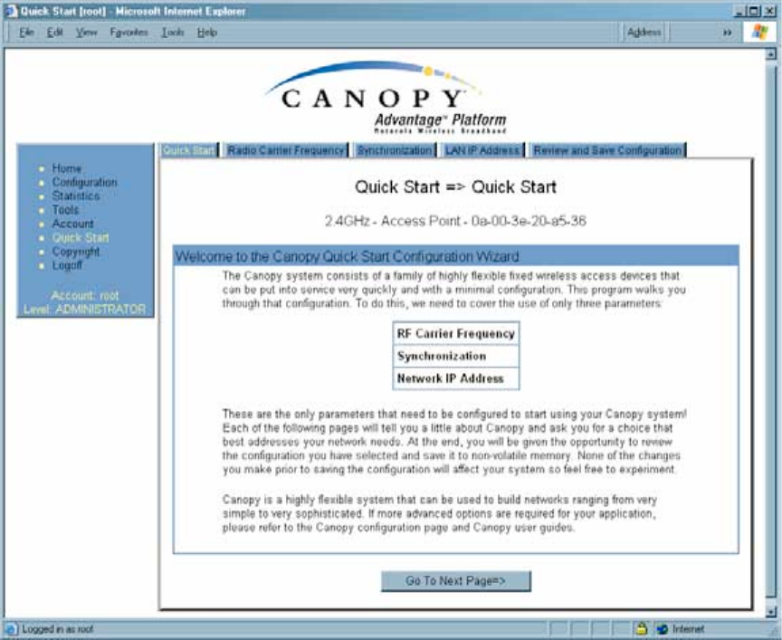
Release 8 Installation and Configuration Guide
Issue 2, November 2007 Draft 5 for Regulatory Review 186
Figure 52: Quick Start tab of AP, example
Quick Start is a wizard that helps you to perform a basic configuration that places an AP
into service. Only the following parameters must be configured:
◦ RF Carrier Frequency
◦ Synchronization
◦ Network IP Address
In each Quick Start tab, you can
◦ specify the settings to satisfy the requirements of the network.
◦ review the configuration selected.
◦ save the configuration to non-volatile memory.
Proceed with the test setup as follows.
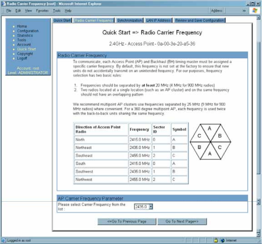
Release 8 Installation and Configuration Guide
Issue 2, November 2007 Draft 5 for Regulatory Review 187
Procedure 7: Using Quick Start to configure a standalone AP for test
1. At the bottom of the Quick Start tab, click the Go To Next Page => button.
RESULT: The AP responds by opening the RF Carrier Frequency tab.
An example of this tab is shown in Figure 53.
Figure 53: Radio Frequency Carrier tab of AP, example
2. From the pull-down menu in the lower left corner of this tab, select a frequency
for the test.
3. Click the Go To Next Page => button.
RESULT: The AP responds by opening the Synchronization tab. An example of
this tab is shown in Figure 54.
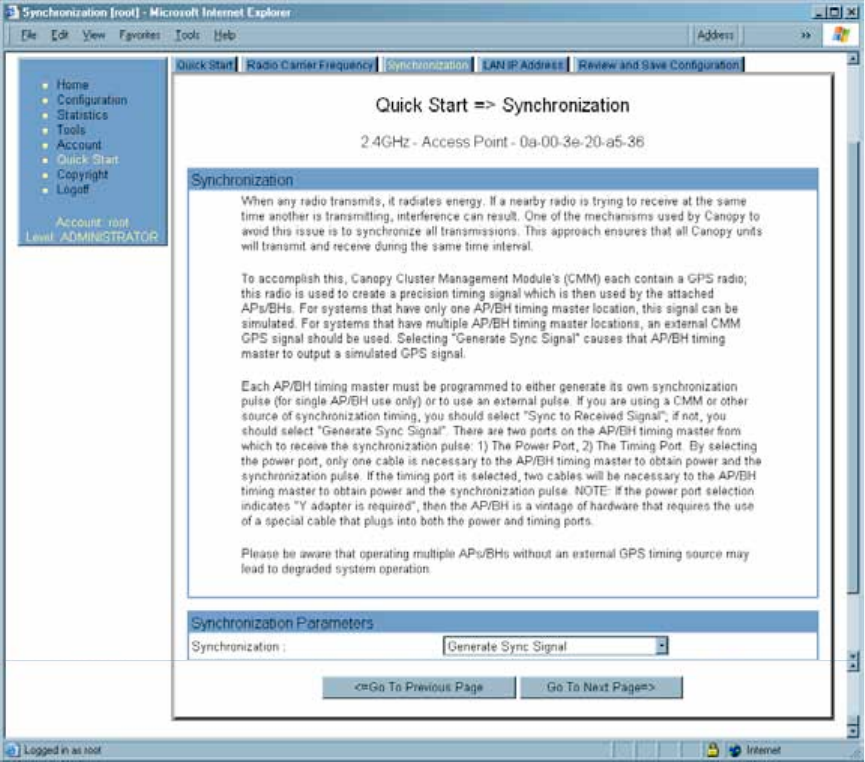
Release 8 Installation and Configuration Guide
Issue 2, November 2007 Draft 5 for Regulatory Review 188
Figure 54: Synchronization tab of AP, example
4. At the bottom of this tab, select Generate Sync Signal.
5. Click the Go To Next Page => button.
RESULT: The AP responds by opening the LAN IP Address tab. An example of
this tab is shown in Figure 55.
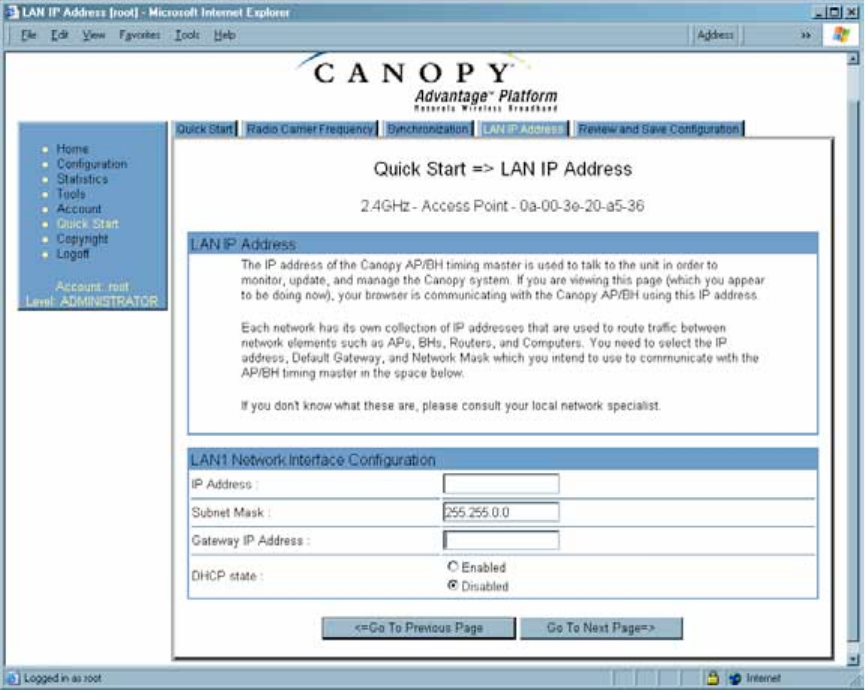
Release 8 Installation and Configuration Guide
Issue 2, November 2007 Draft 5 for Regulatory Review 189
Figure 55: LAN IP Address tab of AP, example
6. At the bottom of this tab, either
◦ specify an IP Address, a Subnet Mask, and a Gateway IP Address for
management of the AP and leave the DHCP state set to Disabled.
◦ set the DHCP state to Enabled to have the IP address, subnet mask, and
gateway IP address automatically configured by a domain name server
(DNS).
7. Click the Go To Next Page => button.
RESULT: The AP responds by opening the Review and Save Configuration tab.
An example of this tab is shown in Figure 56.
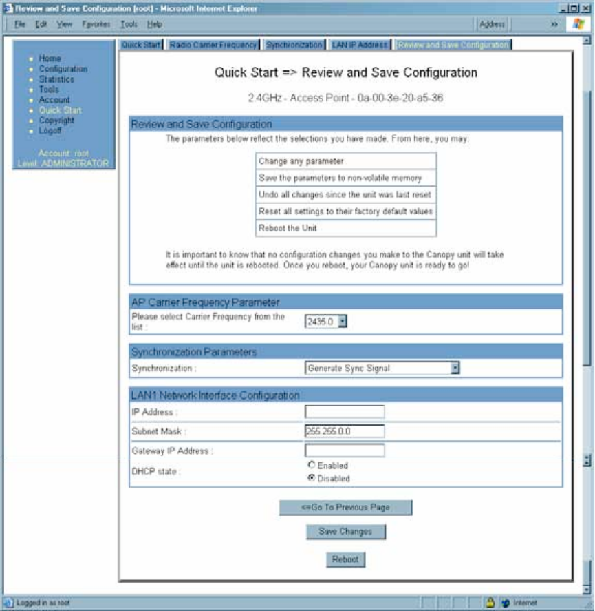
Release 8 Installation and Configuration Guide
Issue 2, November 2007 Draft 5 for Regulatory Review 190
Figure 56: Review and Save Configuration tab of AP, example
8. Ensure that the initial parameters for the AP are set as you intended.
9. Click the Save Changes button.
10. Click the Reboot button.
RESULT: The AP responds with the message Reboot Has Been Initiated…
11. Wait until the indicator LEDs are not red.
12. Trigger your browser to refresh the page until the AP redisplays the General
Status tab.
13. Wait until the red indicator LEDs are not lit.
=========================== end of procedure ===========================
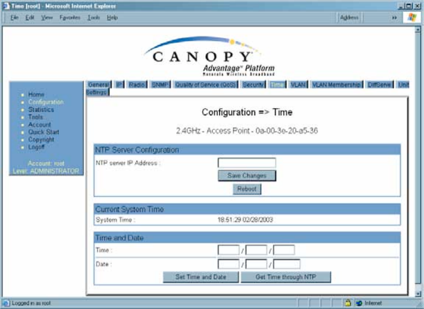
Release 8 Installation and Configuration Guide
Issue 2, November 2007 Draft 5 for Regulatory Review 191
Canopy encourages you to experiment with the interface. Unless you save a
configuration and reboot the AP after you save the configuration, none of the changes
are effected.
16.3.2 Time Tab of the AP
To proceed with the test setup, click the Configuration link on the left side of the General
Status tab. When the AP responds by opening the Configuration page to the General tab,
click the Time tab. An example of this tab is displayed in Figure 57.
Figure 57: Time tab of AP, example
To have each log in the AP correlated to a meaningful time and date, either a reliable
network element must pass time and date to the AP or you must set the time and date
whenever a power cycle of the AP has occurred. A network element passes time and
date in any of the following scenarios:
◦ A connected CMM2 passes time and date (GPS time and date, if received).
◦ A connected CMMmicro passes the time and date (GPS time and date, if
received), but only if both the CMMmicro is operating on CMMmicro Release 2.1
or later release. (These releases include an NTP server functionality.)
◦ A separate NTP server is addressable from the AP.
If the AP should obtain time and date from either a CMMmicro or a separate NTP server,
enter the IP address of the CMMmicro or NTP server on this tab. To force the AP to
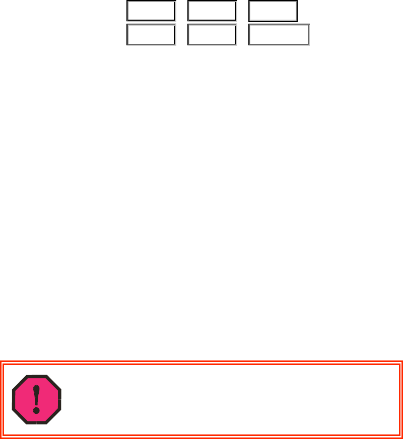
Release 8 Installation and Configuration Guide
Issue 2, November 2007 Draft 5 for Regulatory Review 192
obtain time and date before the first (or next) 15-minute interval query of the NTP server,
click Get Time through NTP.
If you enter a time and date, the format for entry is
Time :
hh
/
mm
/
ss
Date :
MM
/
dd
/
yyyy
where
hh
represents the two-digit hour in the range 00 to 24
mm
represents the two-digit minute
ss
represents the two-digit second
MM
represents the two-digit month
dd
represents the two-digit day
yyyy
represents the four-digit year
Proceed with the test setup as follows.
◦ Enter the appropriate information in the format shown above.
◦ Then click the Set Time and Date button.
NOTE: The time displayed at the top of this page is static unless your browser is
set to automatically refresh.
Procedure 8: Setting up the SM for test
1. In one hand, securely hold the top (larger shell) of the SM. With the other hand,
depress the lever in the back of the base cover (smaller shell). Remove the base
cover.
2. Plug one end of a CAT 5 Ethernet cable into the SM RJ-45 jack.
3. Plug the other end of the Ethernet cable into the jack in the pig tail that hangs
from the power supply.
4. Roughly aim the SM toward the AP.
WARNING!
From this point until you remove power from the SM, stay at least as far from the
SM as the minimum separation distance specified in Table 37 on Page 169.
5. Plug the power supply into an electrical outlet.
6. Repeat the foregoing steps for each SM that you wish to include in the test.
7. Back at the computing device, on the left side of the Time & Date tab, click
Home.
8. Click the Session Status tab.
=========================== end of procedure ===========================
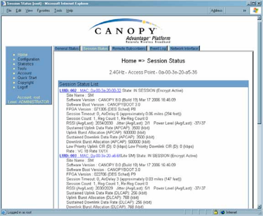
Release 8 Installation and Configuration Guide
Issue 2, November 2007 Draft 5 for Regulatory Review 193
16.3.3 Session Status Tab of the AP
An example of the AP Session Status tab is displayed in Figure 58.
Figure 58: Session Status tab data from AP, example
If no SMs are registered to this AP, then the Session Status tab displays the simple
message No sessions. In this case, try the following steps.
Procedure 9: Retrying to establish a point-to-multipoint link
1. More finely aim the SM or SMs toward the AP.
2. Recheck the Session Status tab of the AP for the presence of LUIDs.
3. If still no LUIDs are reported on the Session Status tab, click the Configuration
button on the left side of the Home page.
RESULT: The AP responds by opening the AP Configuration page.
4. Click the Radio tab.
5. Find the Color Code parameter and note the setting.
6. In the same sequence as you did for the AP directly under Configuring a Point-to-
Multipoint Link for Test on Page 184, connect the SM to a computing device and
to power.
7. On the left side of the SM Home page, click the Configuration button.
RESULT: The Configuration page of the SM opens.

Release 8 Installation and Configuration Guide
Issue 2, November 2007 Draft 5 for Regulatory Review 194
8. Click the Radio tab.
9. If the transmit frequency of the AP is not selected in the Custom Radio
Frequency Scan Selection List parameter, select the frequency that matches.
10. If the Color Code parameter on this page is not identical to the Color Code
parameter you noted from the AP, change one of them so that they match.
11. At the bottom of the Radio tab for the SM, click the Save Changes button.
12. Click the Reboot button.
13. Allow several minutes for the SM to reboot and register to the AP.
14. Return to the computing device that is connected to the AP.
15. Recheck the Session Status tab of the AP for the presence of LUIDs.
=========================== end of procedure ===========================
The Session Status tab provides information about each SM that has registered to
the AP. This information is useful for managing and troubleshooting a Canopy system.
All information that you have entered in the Site Name field of the SM displays in the
Session Status tab of the linked AP.
The Session Status tab also includes the current active values on each SM (LUID) for
MIR, CIR, and VLAN, as well as the source of these values (representing the SM itself,
BAM, or the AP and cap, if any—for example, APCAP as shown in Figure 58 above).
L indicates a Canopy Lite SM, and D indicates from the device. As an SM registers to
the AP, the configuration source that this page displays for the associated LUID may
change. After registration, however, the displayed source is stable and can be trusted.
The Session Status tab of the AP provides the following parameters.
LUID
This field displays the LUID (logical unit ID) of the SM. As each SM registers to the AP,
the system assigns an LUID of 2 or a higher unique number to the SM. If an SM loses
registration with the AP and then regains registration, the SM will retain the same LUID.
NOTE:
The LUID association is lost when a power cycle of the AP occurs.
MAC
This field displays the MAC address (or electronic serial number) of the SM.
State
This field displays the current status of the SM as either
◦ IN SESSION to indicate that the SM is currently registered to the AP.
◦ IDLE to indicate that the SM was registered to the AP at one time, but now is not.
This field also indicates whether the encryption scheme in the module is enabled.
Release 8 Installation and Configuration Guide
Issue 2, November 2007 Draft 5 for Regulatory Review 195
Site Name
This field indicates the name of the SM. You can assign or change this name on the
Configuration web page of the SM. This information is also set into the sysName SNMP
MIB-II object and can be polled by an SNMP management server.
Software Version
This field displays the software release that operates on the SM, the release date and
time of the software.
Software Boot Version
This field indicates the CANOPYBOOT version number.
FPGA Version
This field displays the version of FPGA that runs on the SM.
Session Timeout
This field displays the timeout in seconds for management sessions via HTTP, telnet, or
ftp access to the SM. 0 indicates that no limit is imposed.
AirDelay
This field displays the distance of the SM from the AP. To derive the distance in meters,
multiply the displayed number by 0.3048. At close distances, the value in this field is
unreliable.
Session Count
This field displays how many sessions the SM has had with the AP. Typically, this is the
sum of Reg Count and Re-Reg Count. However, the result of internal calculation may
display here as a value that slightly differs from the sum.
If the number of sessions is significantly greater than the number for other SMs, then this
may indicate a link problem or an interference problem.
Reg Count
When an SM makes a registration request, the AP checks its local data to see whether it
considers the SM to be already registered. If the AP concludes that the SM is not, then
the request increments the value of this field.
Re-Reg Count
When an SM makes a registration request, the AP checks its local data to see whether it
considers the SM to be already registered. If the AP concludes that the SM is not, then
the request increments the value of this field. Typically, a Re-Reg is the case where both
◦ an SM attempts to reregister for having lost communication with the AP.
◦ the AP has not yet observed the link to the SM as being down.
A high number in this field is often an indication of link instability or interference problems.
RSSI, Jitter, and Power Level (Avg/Last)
The Session Status tab shows the received Power Level in dBm and Jitter. Proper
alignment maximizes Power Level and minimizes Jitter. As you refine alignment, you
should favor lower jitter over higher dBm. For example, if coarse alignment gives an SM
a power level of −75 dBm and a jitter measurement of 5, and further refining
Release 8 Installation and Configuration Guide
Issue 2, November 2007 Draft 5 for Regulatory Review 196
the alignment drops the power level to −78 dBm and the jitter to 2 or 3, use the refined
alignment, with the following caveats:
◦ When the receiving link is operating at 1X, the Jitter scale is 0 to 15 with desired
jitter between 0 and 4.
◦ When the receiving link is operating at 2X, the Jitter scale is 0 to 15 with desired
jitter between 0 and 9.
The Session Status tab also shows a historical RSSI, a unitless measure of power. Use
Power Level and ignore RSSI. RSSI implies more accuracy and precision than is
inherent in its measurement.
Sustained Uplink Data Rate
This field displays the value that is currently in effect for the SM, with the source of that
value in parentheses. This is the specified rate at which each SM registered to this AP is
replenished with credits for transmission. The configuration source of the value is
indicated in parentheses. See
◦ Maximum Information Rate (MIR) Parameters on Page 84
◦ Interaction of Burst Allocation and Sustained Data Rate Settings on Page 86
◦ Setting the Configuration Source on Page 292.
Uplink Burst Allocation
This field displays the value that is currently in effect for the SM, with the source of that
value in parentheses. This is the specified maximum amount of data that each SM is
allowed to transmit before being recharged at the Sustained Uplink Data Rate with
credits to transmit more. The configuration source of the value is indicated in
parentheses. See
◦ Maximum Information Rate (MIR) Parameters on Page 84
◦ Interaction of Burst Allocation and Sustained Data Rate Settings on Page 86
◦ Setting the Configuration Source on Page 292.
Sustained Downlink Data Rate
This field displays the value that is currently in effect for the SM, with the source of that
value in parentheses. This is the specified the rate at which the AP should be replenished
with credits (tokens) for transmission to each of the SMs in its sector. The configuration
source of the value is indicated in parentheses. See
◦ Maximum Information Rate (MIR) Parameters on Page 84
◦ Interaction of Burst Allocation and Sustained Data Rate Settings on Page 86
◦ Setting the Configuration Source on Page 292.
Downlink Burst Allocation
This field displays the value that is currently in effect for the SM, with the source of that
value in parentheses. This is the maximum amount of data to allow the AP to transmit to
any registered SM before the AP is replenished with transmission credits at the
Sustained Downlink Data Rate. The configuration source of the value is indicated in
parentheses. See
◦ Maximum Information Rate (MIR) Parameters on Page 84
◦ Interaction of Burst Allocation and Sustained Data Rate Settings on Page 86
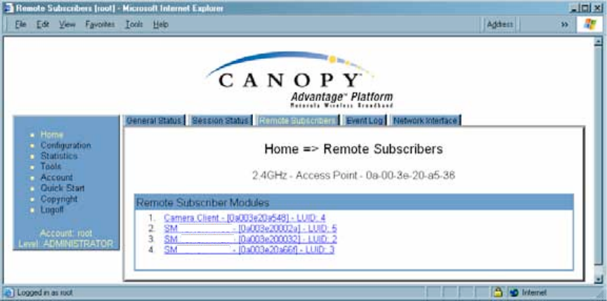
Release 8 Installation and Configuration Guide
Issue 2, November 2007 Draft 5 for Regulatory Review 197
◦ Setting the Configuration Source on Page 292.
Low Priority Uplink CIR
This field displays the value that is currently in effect for the SM, with the source of that
value in parentheses. The configuration source of the value is indicated in parentheses.
See
◦ Committed Information Rate on Page 86
◦ Setting the Configuration Source on Page 292.
Low Priority Downlink CIR
This field displays the value that is currently in effect for the SM, with the source of that
value in parentheses. The configuration source of the value is indicated in parentheses.
See
◦ Committed Information Rate on Page 86
◦ Setting the Configuration Source on Page 292.
Rate
This field displays whether the high-priority channel is enabled in the SM and the status
of 1X or 2X operation in the SM. See Checking the Status of 2X Operation on Page 91.
16.3.4 Beginning the Test of Point-to-Multipoint Links
To begin the test of links, perform the following steps:
1. In the Session Status tab of the AP, note the LUID associated with the MAC
address of any SM you wish to involve in the test.
2. Click the Remote Subscribers tab.
16.3.5 Remote Subscribers Tab of the AP
An example of a Remote Subscribers tab is displayed in Figure 59.
Figure 59: Remote Subscribers tab of AP, example
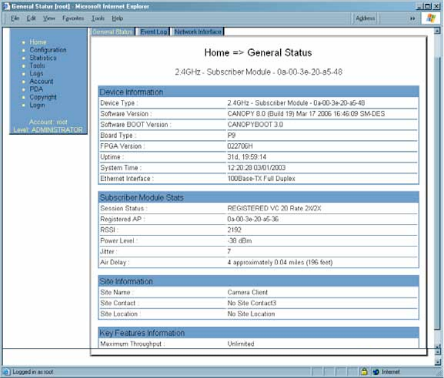
Release 8 Installation and Configuration Guide
Issue 2, November 2007 Draft 5 for Regulatory Review 198
This tab allows you to view the web pages of registered SMs over the RF link. To view
the pages for a selected SM, click its link. The General Status tab of the SM opens.
16.3.6 General Status Tab of the SM
An example of the General Status tab of an SM is displayed in Figure 60.
Figure 60: General Status tab of SM, example
The General Status tab provides information on the operation of this SM. This is the tab
that opens by default when you access the GUI of the SM. The General Status tab
provides the following read-only fields.
Device Type
This field indicates the type of the Canopy module. Values include the frequency band of
the SM, its module type, and its MAC address.
Software Version
This field indicates the Canopy system release, the time and date of the release, and
whether communications involving the module are secured by DES or AES encryption
(see Encrypting Canopy Radio Transmissions on Page 369). If you request technical
support, provide the information from this field.
Release 8 Installation and Configuration Guide
Issue 2, November 2007 Draft 5 for Regulatory Review 199
Software BOOT Version
This field indicates the version of the CANOPYBOOT file. If you request technical
support, provide the information from this field.
Board Type
This field indicates the series of hardware. See Designations for Hardware in Radios on
Page 365.
FPGA Version
This field indicates the version of the field-programmable gate array (FPGA) on the
module. When you request technical support, provide the information from this field.
Uptime
This field indicates how long the module has operated since power was applied.
System Time
This field provides the current time. Any SM that registers to an AP inherits the system
time, which is displayed in this field as GMT (Greenwich Mean Time).
Ethernet Interface
This field indicates the speed and duplex state of the Ethernet interface to the SM.
Session Status
This field displays the following information about the current session:
◦ Scanning indicates that this SM currently cycles through the radio frequencies
that are selected in the Radio tab of the Configuration page.
◦ Syncing indicates that this SM currently attempts to receive sync.
◦ Registering indicates that this SM has sent a registration request message to
the AP and has not yet received a response.
◦ Registered indicates that this SM is both
− registered to an AP.
− ready to transmit and receive data packets.
◦ Alignment indicates that this SM is in an aiming mode. See Table 41 on
Page 179.
Registered AP
This field displays the MAC address of the AP to which this SM is registered.
RSSI, Power Level, and Jitter
The General Status tab shows the received Power Level in dBm and Jitter. Proper
alignment maximizes Power Level and minimizes Jitter. As you refine alignment, you
should favor lower jitter over higher dBm. For example, if coarse alignment gives an SM
a power level of −75 dBm and a jitter measurement of 5, and further refining
the alignment drops the power level to −78 dBm and the jitter to 2 or 3, use the refined
alignment, with the following caveats:
◦ When the receiving link is operating at 1X, the Jitter scale is 0 to 15 with desired
jitter between 0 and 4.

Release 8 Installation and Configuration Guide
Issue 2, November 2007 Draft 5 for Regulatory Review 200
◦ When the receiving link is operating at 2X, the Jitter scale is 0 to 15 with desired
jitter between 0 and 9.
For historical relevance, the General Status tab also shows the RSSI, the unitless
measure of power. Use Power Level and ignore RSSI. RSSI implies more accuracy and
precision than is inherent in its measurement.
NOTE:
Unless the page is set to auto-refresh, the values displayed are from the instant
the General Status tab was selected. To keep a current view of the values,
refresh the browser screen or set to auto-refresh.
Air Delay
This field displays the distance in feet between this SM and the AP. To derive the
distance in meters, multiply the value of this parameter by 0.3048. Distances reported as
less than 200 feet (61 meters) are unreliable.
Site Name
This field indicates the name of the physical module. You can assign or change this
name in the SNMP tab of the SM Configuration page. This information is also set into the
sysName SNMP MIB-II object and can be polled by an SNMP management server.
Site Contact
This field indicates contact information for the physical module. You can provide or
change this information in the SNMP tab of the SM Configuration page. This information
is also set into the sysName SNMP MIB-II object and can be polled by an SNMP
management server.
Site Location
This field indicates site information for the physical module. You can provide or change
this information in the SNMP tab of the SM Configuration page.
Maximum Throughput
This field indicates the limit of aggregate throughput for the SM and is based on the
default (factory) limit of the SM and any floating license that is currently assigned to it.
16.3.7 Continuing the Test of Point-to-Multipoint Links
To resume the test of links, perform the following steps.
Procedure 10: Verifying and recording information from SMs
1. Verify that the Session Status field of the General Status tab in the SM
indicates REGISTERED.
2. While you view the General Status tab in the SM, note (or print) the values of the
following fields:
◦ Device type
◦ Software Version
◦ Software BOOT Version