Motorola Solutions 92FT4887 RPX SERIES REPEATER User Manual 24019 A PORS en
Motorola Solutions, Inc. RPX SERIES REPEATER 24019 A PORS en
UserManual.wiki
>
Motorola Solutions
>
92FT4887 User Manual
>
Users Manual
Contents
1.
Users Manual
2.
Safety Booklet
Users Manual
Navigation menu
Upload a User Manual
Namespaces
Wiki Guide
HTML
PDF
Info
Views
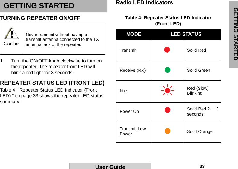
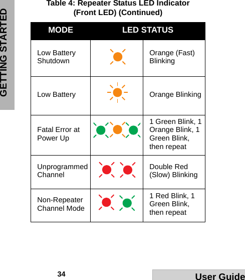
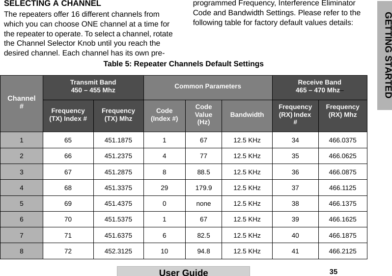
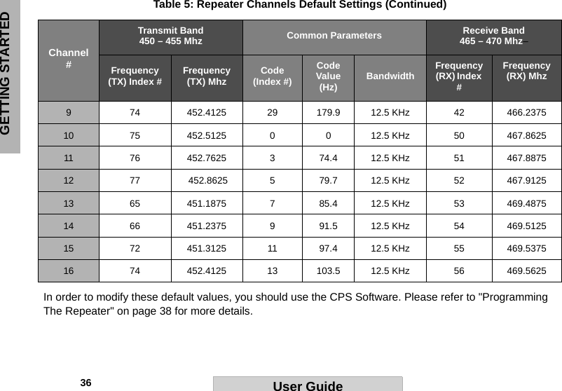
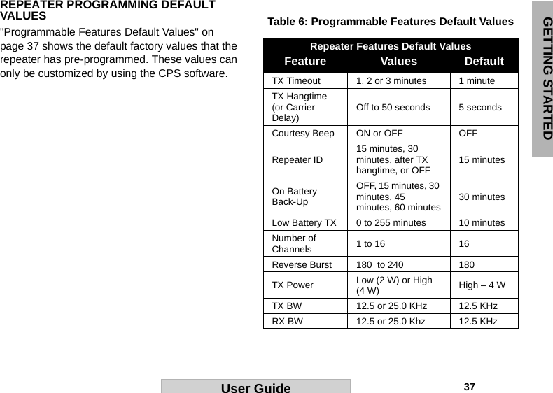
User Manual
Discussion / Help
Navigation