Motorola Solutions 92FT4887 RPX SERIES REPEATER User Manual 24019 A PORS en
Motorola Solutions, Inc. RPX SERIES REPEATER 24019 A PORS en
Contents
- 1. Users Manual
- 2. Safety Booklet
Users Manual
Installation and User Guide
Models RPU2160/RPU4160
Document Copyrights
No duplication or distribution of this document or any portion thereof shall take place without the express
written permission of Motorola. No part of this manual may be reproduced, distributed, or transmitted in
any form or by any means, electronic or mechanical, for any purpose without the express written
permission of Motorola.
Disclaimer
The information in this document is carefully examined, and is believed to be entirely reliable. However,
no responsibility is assumed for inaccuracies. Furthermore, Motorola reserves the right to make changes
to any products herein to improve readability, function, or design. Motorola does not assume any liability
arising out of the applications or use of any product or circuit described herein; nor does it cover any
license under its patent rights nor the rights of others.

CONTENTS
i
CONTENTS
Contents. . . . . . . . . . . . . . . . . . . . . . . . . . . . . i
Computer Software
Copyrights . . . . . . . . . . . . . . . . . . . . . . . . . . iv
Radio Frequency (RF)
Exposure Safety Standards . . . . . . . . . . . . .v
Operational Safety
Guidelines . . . . . . . . . . . . . . . . . . . . . . . . . . . vi
FCC Licensing
Information. . . . . . . . . . . . . . . . . . . . . . . . . viii
Interference Information . . . . . . . . . . . . . . . viii
Introduction . . . . . . . . . . . . . . . . . . . . . . . . . .1
Package Contents. . . . . . . . . . . . . . . . . . . . . .1
About This Manual . . . . . . . . . . . . . . . . . . . . .2
Service Support. . . . . . . . . . . . . . . . . . . . . . . .2
Product Safety. . . . . . . . . . . . . . . . . . . . . . . . .2
Manual Revisions . . . . . . . . . . . . . . . . . . . . . .2
Acronyms . . . . . . . . . . . . . . . . . . . . . . . . . . . .2
Repeater Overview . . . . . . . . . . . . . . . . . . . .3
Parts of the Repeater. . . . . . . . . . . . . . . . . . . 3
Repeater Accessories . . . . . . . . . . . . . . . 5
How the Repeater Works. . . . . . . . . . . . . 8
Pre-Installation Considerations . . . . . . . . 10
RF Coverage Field Test. . . . . . . . . . . . . 10
Choosing a Tentative
Location . . . . . . . . . . . . . . . . . . . . . . . . . 11
Conducting the RF
Coverage Field Test . . . . . . . . . . . . . . . 12
Multiple Repeaters In A Single
Location (Multiple User Groups) . . . . . . . . . 13
Environmental Conditions at
Intended Installation Site(*) . . . . . . . . . . 14
Temperature Ranges. . . . . . . . . . . . . . . 15
Ventilation . . . . . . . . . . . . . . . . . . . . . . . 15
Electrical Requirements . . . . . . . . . . . . . . . . 16
AC/DC Power
Requirements . . . . . . . . . . . . . . . . . . . . 16
Site Grounding and
Lightning Protection. . . . . . . . . . . . . . . . 16
Electrical Ground . . . . . . . . . . . . . . . . . . 16
RF Ground . . . . . . . . . . . . . . . . . . . . . . . 17
Lightning Ground . . . . . . . . . . . . . . . . . . 17

CONTENTS
ii
Repeater Installation. . . . . . . . . . . . . . . . . .18
Repeater Positioning
and Orientation . . . . . . . . . . . . . . . . . . . .18
Antenna Installation
Instructions . . . . . . . . . . . . . . . . . . . . . . .20
Installing External Antenna Using
the Antenna/Magnetic Mount /RF
Cable Kit Accessory . . . . . . . . . . . . . . . .22
RF Cable Installation. . . . . . . . . . . . . . . .24
Installing Exterior Antenna . . . . . . . . . . .25
Uninstalling Exterior Antenna . . . . . . . . .25
Wall Mount Installation
Instructions . . . . . . . . . . . . . . . . . . . . . . .25
AC/DC Power Supply
Connection . . . . . . . . . . . . . . . . . . . . . . .27
Outdoor Installations
Considerations . . . . . . . . . . . . . . . . . . . .28
Outdoors Repeater Temporary
Installation – Example. . . . . . . . . . . . . . .28
Vehicle Adaptor. . . . . . . . . . . . . . . . . . . .29
Alkaline Battery Frame . . . . . . . . . . . . . . . .30
About Alkaline Batteries . . . . . . . . . . . . . . . .30
Alkaline Batteries
Frame Solution . . . . . . . . . . . . . . . . . . . 30
Alkaline Battery
Life Estimation . . . . . . . . . . . . . . . . . . . . 30
Alkaline Battery Power
LED (Side LED) . . . . . . . . . . . . . . . . . . . 31
Installing/Removing the
Alkaline Battery Frame . . . . . . . . . . . . . 31
Li-Ion Battery Frame
(Optional Accessory) . . . . . . . . . . . . . . . . . . 32
Getting Started . . . . . . . . . . . . . . . . . . . . . . 33
Turning Repeater On/Off . . . . . . . . . . . . . . . 33
Repeater Status Led
(Front LED) . . . . . . . . . . . . . . . . . . . . . . . . . 33
Radio LED Indicators. . . . . . . . . . . . . . . 33
Selecting A Channel. . . . . . . . . . . . . . . . . . . 35
Repeater Programming
Default Values . . . . . . . . . . . . . . . . . . . . . . . 37
Programming The Repeater . . . . . . . . . . . 38
Programming Features Overview . . . . . . . . 38
Programming the Repeater
Using the CPS . . . . . . . . . . . . . . . . . . . . 40
How to Read and

CONTENTS
iii
Modify Your Repeater’s
Features . . . . . . . . . . . . . . . . . . . . . . . . .41
Programming Your
Radios . . . . . . . . . . . . . . . . . . . . . . . . . . . . .43
Programming Your RDX
4 W Radios To Work With
The Repeaters. . . . . . . . . . . . . . . . . . . . . . . .43
Repeater Cloning. . . . . . . . . . . . . . . . . . . . .46
RDX Radio to Repeater
Cloning . . . . . . . . . . . . . . . . . . . . . . . . . . . . .46
Operating Instructions . . . . . . . . . . . . . . . . . .47
Cloning Instructions. . . . . . . . . . . . . . . . . . . .47
Troubleshooting . . . . . . . . . . . . . . . . . . . . .50
Use and Care . . . . . . . . . . . . . . . . . . . . . . . .53
Motorola Limited Warranty
for the United States
and Canada . . . . . . . . . . . . . . . . . . . . . . . . .54
Accessories . . . . . . . . . . . . . . . . . . . . . . . . .59
RPX Repeater
Series Accessories . . . . . . . . . . . . . . . . . . . .59
Antenna Accessories . . . . . . . . . . . . . . . . . 59
Batteries Accessories. . . . . . . . . . . . . . . . . . 59
Power Supplies
Accessories . . . . . . . . . . . . . . . . . . . . . . . . . 59
Battery Accessories . . . . . . . . . . . . . . . . . . . 59
RDX Pick-Up Radios and
Accessories . . . . . . . . . . . . . . . . . . . . . . . . . 60
Cables Accessories . . . . . . . . . . . . . . . . . . . 60
Charger Accessories . . . . . . . . . . . . . . . . . . 60
2-Way RDX Repeater
Capable UHFRadios . . . . . . . . . . . . . . . . . . 60
Appendix A: Repeater
Specifications. . . . . . . . . . . . . . . . . . . . . . . 61
Appendix B: Repeater
Lightning Protection . . . . . . . . . . . . . . . . . 69
How To Minimize Lightning
Damage for RPX Repeater
Series™ System. . . . . . . . . . . . . . . . . . . 69
AC Line
Requirements: . . . . . . . . . . . . . . . . . . . . 69
RF Protection
Instructions: . . . . . . . . . . . . . . . . . . . . . . 69

COMPUTER SOFTWARE
COPYRIGHTS
iv
COMPUTER SOFTWARE
COPYRIGHTS
The Motorola products described in this
manual may include copyrighted Motorola
computer programs stored in semiconductor
memories or other media. Laws in the United
States and other countries preserve for
Motorola certain exclusive rights for
copyrighted computer programs, including, but
not limited to, the exclusive right to copy or
reproduce in any form the copyrighted
computer program. Accordingly, any
copyrighted Motorola computer programs
contained in the Motorola products described in
this manual may not be copied, reproduced,
modified, reverse-engineered, or distributed in
any manner without the express written
permission of Motorola.
Furthermore, the purchase of Motorola
products shall not be deemed to grant either
directly or by implication, estoppels, or
otherwise, any license under the copyrights,
patents or patent applications of Motorola,
except for the normal non-exclusive license to
use that arises by operation of law in the sale of
a product.

SAFETY STANDARDS
v
RADIO FREQUENCY (RF)
EXPOSURE SAFETY
STANDARD
!
To ensure compliance to RF Energy Safety
Standards:
• Install only Motorola approved antennas and
accessories
• Be sure that Product Safety and RF Safety
Booklet (P/N 68007024074) enclosed with this
radio is available to the end user upon
completion of the installation of this radio
For a list of Motorola-approved antennas and other
accessories, visit the following web site which lists
approved accessories for your radio model:
http://www.motorola.com/RPX
Before using this product, read
the operating instructions and
RF energy awareness
information contained in the
Product Safety and RF
Exposure booklet (Motorola
P/N 68007024074) enclosed
with your radio.
!
C a u t i o n

vi
SAFETY STANDARDS
OPERATIONAL SAFETY GUIDELINES
1. Read these instructions.
2. Keep these instructions.
3. Heed all warnings.
4. Follow all instructions.
5. Do not use this apparatus near water.
6. Clean only with a damp cloth.
7. Do not block any of the ventilation openings.
Install in accordance with the manufacturer’s
instructions.
8. Do not install near any heat sources such as
radiators, heat registers, stoves, or other
apparatus (including amplifiers) that produce
heat.
9. Do not defeat the safety purpose of the
polarized or grounding-type plug. A polarized
plug has two blades with one wider than the
other. A grounding type plug has two blades and
a third grounding prong. The wide blade or the
third prong are provided for your safety. When
the provided plug does not fit into your outlet,
consult an electrician for replacement of the
obsolete outlet.
10. Protect the power cord from being walked on or
pinched particularly at plugs, convenience
receptacles, and the point where they exit from
the apparatus.
11. Use only the attachments/accessories specified
by the manufacturer.
12. Use only on a stable, flat surface or install using
the wall mount holster that comes with this
product. When a cart is used for transporting
this device, use caution when moving the cart/
apparatus combination in order to avoid injury
from tip-over.
13. Unplug this apparatus during lightning storms or
when unused for long periods of time.
14. Refer all servicing to qualified service
personnel. Servicing is required when the
apparatus has been damaged in any way, such
as power-supply cord or plug is damaged, liquid
has been spilled or objects have fallen into the
apparatus, the apparatus has been exposed to
rain or moisture, does not operate normally, or
has been dropped.
15. The power supply is not suitable for outdoor
use. Use only in dry locations/conditions.
16. Connect the power supply only to an
appropriately fused and wired supply of the
correct voltage (as specified on the product).

SAFETY STANDARDS
vii
17. Disconnect the power supply from the line
voltage by removing the main plug. The outlet
to which this equipment is connected should be
nearby and easily accessible.
18. Maximum ambient temperature around the
power supply equipment must not exceed 40°C
(104°F).
19. Make sure that the cord is located where it will
not be stepped on, tripped over, or subjected to
water, damage or stress.

viii
FCC LICENSING
INFORMATION
FCC LICENSING
INFORMATION
INTERFERENCE INFORMATION
This device complies with Part 15 of the FCC Rules.
Operation is subject to the condition that this device
does not cause harmful interference.
The RPX Repeater Series™ operate on radio
frequencies that are regulated by the Federal
Communications Commission (FCC). To transmit on
these frequencies, you are required to have a license
issued by the FCC. Application is made available on
FCC Form 601 and Schedules D, H, and Remittance
Form 159.
When using portable hand held units with this
repeater, please note that there is an output power
limitation according to FCC's rule part 90.267. This
regulation limits the maximum output power of
portable units to 2 W when used with a repeater
operating on frequencies in the 450 – 470 MHz band
allocated for Industrial/Business use.
To obtain these FCC forms, request document
000601 which includes all forms and instructions. If
you wish to have the document faxed, mailed or have
questions, use the following contact information.
Faxed contact the
Fax-On-Demand
system at:
Mailed call the FCC forms hotline
at: For questions regarding FCC
license, contact the FCC at:
1-202-418-0177 1-800-418-FORM
1-800-418-3676 1-888-CALL-FCC
1-888-225-5322
Or: http://www.fcc.gov

FCC LICENSING
INFORMATION
ix
Before filling out your application, you must decide
which frequency(ies) you can operate on: “Appendix
A: Repeater Specifications” on page 61. For questions
on determining the radio frequency, call Motorola
Product Services at: 1-800-448-6686.
Changes or modifications not expressly approved by
Motorola may void the user’s authority granted by the
FCC to operate this radio and should not be made. To
comply with FCC requirements, transmitter
adjustments should be made only by or under the
supervision of a person certified as technically
qualified to perform transmitter maintenance and
repairs in the private land mobile and fixed services as
certified by an organization representative of the user
of those services.
Replacement of any transmitter component (crystal,
semiconductor, etc.) not authorized by the FCC
equipment authorization for this radio could violate
FCC rules.
Use of this radio outside the country where it was
intended to be distributed is subject to government
regulations and may be prohibited.

x
FCC LICENSING
INFORMATION
Notes

INTRODUCTION
1
INTRODUCTION
Congratulations on your Motorola® RPX Repeater
Series™ purchase!
This repeater is a product of Motorola's 80 plus years
of experience as a world leader in the designing and
manufacturing of communications equipment. The
RPX Repeater Series™ provide cost-effective
communications for businesses such as retail stores,
restaurants, schools, construction sites,
manufacturing, property and hotel management and
more. Motorola Business Radios and Repeater
devices are the perfect communications solution for
all of today's fast-paced industries.
Note: Read this user guide carefully to ensure
you know how to properly operate the
repeater before use.
PACKAGE CONTENTS
Your product package contains the following products
and manuals:
• Repeater (includes the Alkaline Battery Frame)
• Antenna
• Power Supply
• Wall holster mount
• User Guide, CD and Quick Reference Leaflet
• Warranty Card
• Product Safety & RF Exposure Booklet
For product information, visit us at:
www.motorola.com/radios/business
or visit our micro-site at: www.motorola.com/RPX
For User Guide or product-related questions, contact:
1-800-448- 6686 in the USA
1-800-461-4575 in Canada
1-866-522-5210 on your TTY (Text Telephone)
You can also send mail to us at:
Business Radios,
RPSD 1C15, Motorola
8000 West Sunrise Boulevard
Plantation, Florida 33322

2
INTRODUCTION
ABOUT THIS MANUAL
This manual contains installation information required
for the RPX Repeater Series™ repeaters.
SERVICE SUPPORT
For information related to the service support
(including software, replacement parts and
accessories for the RPX Repeater Series™), contact
your Motorola Authorized Distributors and Resellers
via MOL (Motorola On-Line Tool).
For all other inquiries about service information,
please call your Motorola Point of Contact or call:
1-800-448-6686 in the USA
1-800-461-4575 in Canada
1-866-522-5210 on your TTY (Text Telephone)
PRODUCT SAFETY
For information related to RF Exposure compliance
and Batteries and Chargers Safety, please refer to
“Radio Frequency (RF) Exposure Safety Standards”
on page v.
MANUAL REVISIONS
Changes may occur after this manual is printed. To
obtain an updated or latest version of this manual,
please go to: http://www.motorola.com/RPX
ACRONYMS
The explanations in this manual will be using the
following acronyms:
AC: Alternate Current
DC: Direct Current
RX: Receiving Frequency
TX: Transmitting Frequency
CX: Connected
DX: Disconnected
RF: Radio Frequency
P/N: Part Number
Table 1: RPX Repeater Series™ Models
Label
Model Frequency
Band Output
Power Number of
Channels
Battery
Default
Type
RPU2160 UHF 2 W 16 Alkaline
RPU4160 UHF 4 W 16 Alkaline
3
REPEATER OVERVIEW
REPEATER OVERVIEW
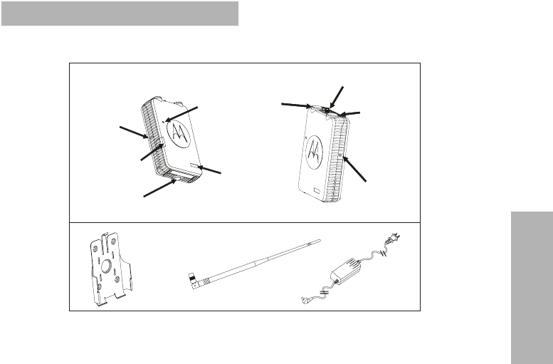
PARTS OF THE REPEATER
Dipole UHF Antenna
Channel
Knob
ON/OFF
Knob
Power LED
Indicator
Antenna
Connector
Status LED
Indicator
Programming
Connector
DC/AC
Connector
Battery Frame (*)
Model Label
Wall Mount
AC/DC Power Supply
(*) RPU4160 repeater model comes with standard Alkaline Battery Frame
Figure 1. Repeater Parts

English 4
REPEATER OVERVIEW
Repeater Parts
The repeaters are compatible with 2 - way
repeater capable business radios. Please refer
to "Programming Your Radios” on page 43 for
more information on how to program the RDX
radios to work with the repeater. For RDX radio
model information details, please contact your
Motorola Point of Sale.
1. On/Off Knob
Use to turn the repeater ON or OFF.
2. Channel Selector Knob
Use to switch the repeater for up to 16
different channels. Please refer to "Getting
Started” on page 33 for more information.
3. Model Label
Indicates the model of the repeater.
4. Antenna
Removable UHF 450 – 470 dipole antenna.
Please refer to "Repeater Installation” on
page 18 for more information.
5. Status LED Indicator
Use to indicate, among others, repeater’s
power up and transmission status. Please
refer to the "Getting Started” on page 33 for
more information.
6. Power LED Indicator
One side LED indicator gives repeater AC/
DC connection status whenever the repeater
is working on alkaline Battery Frame
(standard repeater model). Two LED side
indicators give AC/DC connection and
charging status whenever the repeater is
working on Li-Ion Battery Frame. Please
refer to "Alkaline Batteries Frame Solution”
on page 30 for more information.
7. AC/DC Connector
Use to connect the AC/DC power supply.
8. Programming Connector
Use to connect the repeater to a PC in order
to program. (CPS Programming Cable
(P/N RKN4155) required). Please refer to the
"Programming The Repeater” on page 38 for
more information.

5
REPEATER OVERVIEW
9. Alkaline Battery Frame
The repeaters’ standard package includes
the Alkaline Battery frame. Refer to "Alkaline
Battery Frame” on page 30 for more
information.
10. Repeater Power Supply
The repeaters are equipped with AC/DC
power supply to connect the repeaters to AC
or DC power sources.
Repeater Accessories
The repeaters include different types of
accessories that are sold separately. Please
refer to the "Accessories” on page 59 for more
information.
1. Lithium-Ion (Li-Ion) Battery Frame
Li-Ion Battery Frame (P/N HKHN4004A)
allows the use of high capacity Li-Ion
batteries in giving up to 16 hours of battery
back up operation.
2. Antenna, Magnetic Mount and RF Cable
Kit
The repeaters’ accessories offers an
Antenna/Magnetic Mount/RF Cable Kit (P/N
HKKN4022). This external antenna
accessory is strongly recommended in order
to allow the repeater antenna to have a
better coverage. Please refer to "Repeater
Installation” on page 18 for more information.
3. Vehicle Car Power Supply Adaptor
For your convenience, the repeaters’
portfolio includes a Vehicle Adaptor (also
known as “Cigarette Lighter Adaptor” P/N
HKPN4003). Please refer to "Outdoor
Installations Considerations” on page 28 for
more information.
4. Repeater Software (CPS)
The repeaters offer the convenient capability
of customizing your repeater features by
using the CPS (Computer Programming
Software). Please refer to the "Programming
The Repeater” on page 38 for more
information. For Software download
information, contact your Motorola Distributor
or Reseller.

English 6
REPEATER OVERVIEW
Repeater General Applications
The repeaters are ideal as a range extender, that
can help reach other users in areas that are
normally not covered by a 2-way radio’s range.
They are also very useful to help resolve the
common problem of the “dead spots” that are
created when there are terrain obstructions (like
hills or trees), concrete building structures or
architectural designs that interfere with the radio
signal(1).
The repeaters are designed to satisfy both 810 Mil
spec as well IP55 (*) level water and dust ingress
protection. This rugged device can stand harsh
environments(2) making it ideal for outdoors
operations. Its light weight and various back-up
power options (like alkaline/Li-Ion Batteries
Frames and Vehicle Adaptor) make this repeater a
perfect portable solution for temporary outdoor
applications.
The repeaters operate in the UHF 450 – 470 MHz
band providing 16 channels(3) with different pre-
programmed settings. This particular feature
allows easy and quick in field repeater deployment
whenever there is need to setup more than one
repeater for different users’ groups.
Fully and easily programmable, the repeaters give
the flexibility to customize frequencies, codes and
other features according to specific needs(4).
A key advantage for the repeaters is that the
radios have been designed to be compatible with
the UHF RDX 2-way, repeater capable radios.
Enjoy the convenience of picking up RDX
accessories (high capacity batteries, chargers and
programming cables) and re-use them with your
repeaters. This clever inter operability feature will
allow you also to get the most out of your complete
radios and repeater system solution by offering
cloning and programming among radios and
repeaters.

7
REPEATER OVERVIEW
.Note: (1) The repeaters work best when located in
an ideal place that can have good reception
for re-transmitting the signal without any
problems. Refer to "Pre-Installation
Considerations” on page 10 for more
information.
(2) The repeaters are not submersible
devices (Refer to "Appendix A: Repeater
Specifications” on page 61 for more
information) and it is NOT an FM (Factory
Mutual) certified device.
(3) Out of the 16 pre-programmed channels
that are available out of the box, you can
select only ONE channel each time you TX/
RX with the repeater. The repeaters are NOT
multi-channel repeaters.
(4) The repeaters’ CPS software is required.
Refer to "Programming The Repeater” on
page 38 for more information.
Figure 2a. Repeater Application Example –
Indoors
Figure 2b. Repeater Application Example –
Outdoors
English 8
REPEATER OVERVIEW
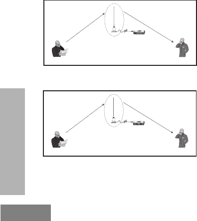
How the Repeater Works
The repeater allows 2-way radios, base stations
or call boxes to communicate through the
repeater in order to extend the coverage range
and/or overcome dead communication spots.
In the Figure 3a, the repeater will get the signal “X”
that Paul transmits from his radio and will convert
it into a “Y” frequency that will re-transmit to Tom.
In Figure 3b, when Tom answers back to Paul, his
radio will also use the “X” frequency to transmit.
The repeater will do the same frequency
conversion (“X” to “Y”) and will re-transmit it to
Paul using frequency “Y”.
Not only Paul and Tom will be able to
communicate using “X” and “Y” frequencies, but
so will all other 2-way, repeater capable radios that
may be in the area* working on those same
frequencies settings.
Note: The repeater needs to re-transmit in a
different frequency from what it received in
order to avoid interferences.
The following are estimations of the repeaters’ talk
coverage range with the repeater located indoors.
Refer to Table 3 "Repeater Alkaline Frame Power
LED (Side) " on page 31 and "Figure 4. Estimated
Outdoors Coverage Range” on page 9 for more
information.
TX in an “X” frequency
RX in the “Y” frequency
Repeater RX the “X” frequency from Paul
and re-TX it to Tom using “Y” frequency
Paul Tom
Figure 3a. How the Repeater Works (TX)
RX in an “Y” frequency
TX in the “X” frequency
Repeater RX the “X” frequency from Tom
and re-TX it to Paul using “Y” frequency
Paul Tom
Figure 3b. How the Repeater Works (RX)

9
REPEATER OVERVIEW
As seen in Figure 4, the maximum antenna
height for low power fixed stations is limited to
23 meters (75 feet) above ground. For stations
operating at fixed locations for temporary
periods, the antenna height is limited to 7
meters (20 feet) above ground.
Note: Proper programming of the repeater (Refer
to "Programming The Repeater” on page 38
section for more information) and optimal
repeater antenna location are the most
important factors that will determine the
coverage and quality of your repeater
communications. It is highly recommended
to refer to "Pre-Installation Considerations”
on page 10 before proceeding to install the
repeater. Make sure your 2-way radios are
repeater capable (able to manage separate
TX and RX frequencies for the same
channel). Refer to "Programming The
Repeater” on page 38 for more information.
Table 2: Estimated Talk Range
Model Industrial Outdoors
Inside steel/concrete
industrial buildings Line of sight/No
obstructions
UHF 2 W Up to 420,000 square
feet 14 miles
UHF 4 W Up to 600,000 square
feet 9 miles
Note: These are estimated maximum ranges that
assume ideal location, environmental and
terrain conditions for the repeater operation.
6 Miles Max.
15 Miles Max. for a 4W repeater.
75 Ft
Repeater Antenna
Figure 4. Estimated Outdoors Coverage Range

10
PRE-INSTALLATION
CONSIDERATIONS
Installation Guide
PRE-INSTALLATION
CONSIDERATIONS
Proper repeater installation ensures the best
possible performance and reliability of the
repeaters. Pre-installation planning is required to
make sure you take into account.
• RF coverage field test to decide mounting
location of the repeater in relation to input
power and antennas
• Site Environmental Conditions
• Electrical Requirements
• Proper programming of the repeater’s
parameters (in order to assure interoperability
with other radio devices).'Programming The
Repeater' on page 38 for more information.
Note: You must read the entire pre-installation
chapter in order to assure proper repeater
operation.
RF Coverage Field Test
The following instructions* are quick and easy tips
to test the RF coverage area and decide the best
position for the Repeater Antenna (either with the
antenna directly installed into the repeater device
or using the antenna/magnetic mount/ RF cable
accessory kit (P/N HKKN4022).
This field coverage test will need to be performed
by at least two people, each one with a fully
charged 2-way radio. Before the test, make sure
the radios are programmed exactly on the same
parameters (frequencies, codes, bandwidth, etc.)
and are operating in talk around mode.
Note: (*) These instructions are not intended to
replace a professional RF field test.

PRE-INSTALLATION
CONSIDERATIONS
11
Installation Guide
Choosing a Tentative Location
Prior to the RF coverage field test, you must first
decide which would be the tentative locations for
the repeater. You should have different options
that will be evaluated according to the following
aspects:
• Location should be as centered as possible to
the area that is being intended for coverage
so the signal strength is at the same level as
possible for all points.
• If the repeater is to be located inside a
building, for example, try to look for a height
vertically centered location as well.
• Location should meet minimum environmental
requirements. (Please refer to 'Environmental
Conditions at Intended Installation Site(*)' on
page 14 for more information).
• If you are planning to use the repeater to
cover a large area with different buildings, it is
strongly recommended that you use the
antenna/magnetic mount and RF Cable
Accessory Kit to install the repeater antenna
in a high point that allows as much as possible
line of sight (**) to most of the area to be
covered. Bear in mind that most of the times,
increasing the repeater’s antenna height will
improve the coverage, but is not necessarily
always the case.
• If you are planning to have an indoors
installation for the repeater, double check that
the environmental and electrical installation
requirements described in the following
sections are feasible.
Note: (**) Means sight from the repeater free of
obstructions at the naked eye.

12
PRE-INSTALLATION
CONSIDERATIONS
Installation Guide
Conducting the RF Coverage Field Test
The objective of the field test is to “simulate” the
transmission quality and coverage that the
repeater may have based upon a chosen location.
This type of testing and planning becomes very
useful as it can save you extra work and money as
a poor location and/or adverse environmental
conditions can affect the repeater’s performance.
To do so, one person should remain in the
tentative repeater location and the second person
should start walking around the area intended to
be covered, while transmitting with the radio.
If the quality communication between the two way
radios is good, this will mean that the repeater
transmissions should be OK.
The test can be conducted by more than two
people, as long as the first one remains fixed on
the repeater location under evaluation.
Note: If you’re planning to have an external
antenna installation, you should try to mimic,
as much as possible, the antenna
positioning to replicate the antenna’s height.
Figure 5: Conducting the RF Coverage
Field Test

PRE-INSTALLATION
CONSIDERATIONS
13
Installation Guide
During this RF test coverage, one of the key field
conditions to test are those spots that will be the
most likely to be used for most of the people
(indoors and/or outdoors) and those that may
appear particularly challenging due to concrete/
steel walls, building architecture, obstructions (like
trees or vertical fire panels in ceilings or walls) and
terrain shape. Make sure you walk around all
those places in order to test reception and
transmission signal strength.
Conduct the test transmitting preferably on those
settings that you will plan to have your radios and
repeater programmed(*). If possible, repeat the
test using different frequencies and codes.
Note: (*) Remember TX range for the repeater is
450 – 455 MHz and RX range is 465 – 470
MHz.
If the reception coverage is below expectations, try
changing the height of the antenna or the repeater
location (do one change at a time so you can track
what is really affecting the coverage) and repeat
the field test coverage.
MULTIPLE REPEATERS IN A SINGLE
LOCATION (MULTIPLE USER
GROUPS)
As the repeaters have 16 different programmable
channels to choose from for setting up the TX/RX
frequency pairs, it is possible to configure multiple
repeaters in the same location or around the same
area.
30 ft min.
30 ft min.
30 ft min.
Figure 6. Multiple Repeaters installations (One
User Group)

14
PRE-INSTALLATION
CONSIDERATIONS
Installation Guide
Whenever you need to expand the 2-way radios’
coverage in the same area but for different user’s
groups, you can use multiple repeaters located at
the same site. For ensuring that the different
groups will not be interfering with each other and
that each one will have their private
communications, each repeater and the radios set
must have different channel settings (please refer
to 'Antenna Installation Instructions' on page 20
and 'Programming The Repeater' on page 38 for
more information). Additionally, for this case,
make sure the channel TX/RX frequency
separations between the different repeaters is at
least 1 MHz.
Note: For other requirements (environmental,
electrical and mechanical), make sure you
read sections ahead, especially information
related to equipment ventilation.
Environmental Conditions at Intended
Installation Site(*)
A key factor for repeater performance is to
accurately evaluate the site environment where
the repeater will be installed. Plan the installation,
paying particular attention to environmental
conditions at the site like temperature, humidity,
dust and ventilation.
The repeater may be installed in any indoors
location suitable for electronic communications
equipment or outdoors temporary/semi-permanent
installations, provided that the environmental
conditions do not exceed the equipment
specifications for temperature, humidity, and air
quality according to Mil 810 and IP55 ruggedness
specifications (For specification details, please
refer to 'Appendix A: Repeater Specifications' on
page 61).

PRE-INSTALLATION
CONSIDERATIONS
15
Installation Guide
Temperature Ranges
This is the temperature measured in close
proximity to the repeater. For example, if the
repeater is mounted in a cabinet, the temperature
that is measured is within the cabinet.
This temperature threshold applies both for
outdoors and indoors repeater operation.
Operating Temperature Range
-30°C (-22°F) to +60°C (+140°F)
Storage Temperature Range
-40°C (-40°F) to +85°C (+185°F)
Humidity & Water(*)
Do not to exceed 95% relative humidity (RH) @
(-30°C (-22°F) to +60°C (+140°F)).
Note: The Repeaters are IP55 water resistant
devices, able to withstand water exposure
for certain periods of time. Bear in mind that
the repeaters are NOT submersible.
Ventilation
Also important is to make sure that there is
adequate ventilation i.e. cabinets with ventilation
slots (for air circulation), especially if multiple
equipments are installed in the same room. In
which case, a minimum distance of open space
between the devices is recommended.
Note: (*) Please refer to 'Appendix A: Repeater
Specifications' on page 61 for specification
details.

16
PRE-INSTALLATION
CONSIDERATIONS
Installation Guide
ELECTRICAL REQUIREMENTS
AC/DC Power Requirements
The repeater comes equipped with a AC/DC
power supply, that operates from 110 Vac to 240
Vac at 50 Hz to 60 Hz.
The outlet must be connected to an AC source
capable of supplying a maximum of 280 W. For a
nominal 110/120 Vac input, the AC source must be
able to supply 5 A and should be protected by
circuit breaker rated at 15 A. For a nominal 220/
240 Vac input, the AC source must be able to
supply 3 A and should be protected by a circuit
breaker rated at 10 A.
The DC power requirement is 12 V (+/- 10%).
Note: The AC socket must be installed near the
equipment and must be easily accessible.
Consideration should be given to the
connection of the equipment to the supply
circuit and the effect that overloading of the
circuits might have on over current
protection and supply wiring. Appropriate
consideration of equipment ratings should
be used when addressing this concern.
Site Grounding and Lightning
Protection
One of the most important considerations when
designing a communications site is the ground
and lightning protection system. Make sure
installations meet all local and state building codes
in you area.
Electrical Ground
Ground wires carrying electrical current from
circuitry or equipment at the site is included in the
category of electrical ground. Examples include
the AC or DC electrical power used to source
equipment located at the site, and wires or cables
connected to alarms or sensors located at the site.
Proper site grounding and lightning
protection are vitally important
consideration, Failure to provide
proper lighting protection may result
in permanent damage to the
repeater equipment. Please refer to
'Appendix B: Repeater Lightning
Protection' on page 69 for basic
instruction.
!
C
a u t i o
n

PRE-INSTALLATION
CONSIDERATIONS
17
Installation Guide
RF Ground
This type of ground is related to the transmission
of the radio frequency energy to earth ground. An
example of RF grounding is the use of shielding to
prevent or at least minimize the leakage of
unwanted RF transmissions from communications
equipment and cables.
Lightning Ground
Providing adequate lightning protection is critical
to a safe reliable communications site. RF
transmission cables, and AC and DC power lines
must all be protected to prevent lightning energy
from entering the site building.
Although a comprehensive coverage of the site
grounding technique and lightning protection is not
within the scope of this instruction manual, there
are several excellent industry sources for rules
and guidelines on ground and lightning protection
at communications site.
Note: Motorola recommends the following
reference source: “Motorola Quality
Standards Fixed Network Equipment
Installation Manual R56” P/N 6881089E50.

18
REPEATER
INSTALLATION
Installation Guide
REPEATER INSTALLATION
For the explanations in this chapter, please refer to
the “Parts of the Repeater” on page 3 under
“Repeater Overview” for more information.
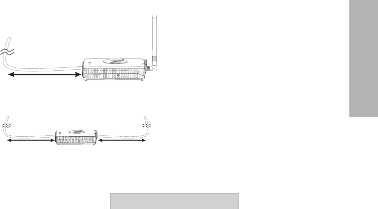
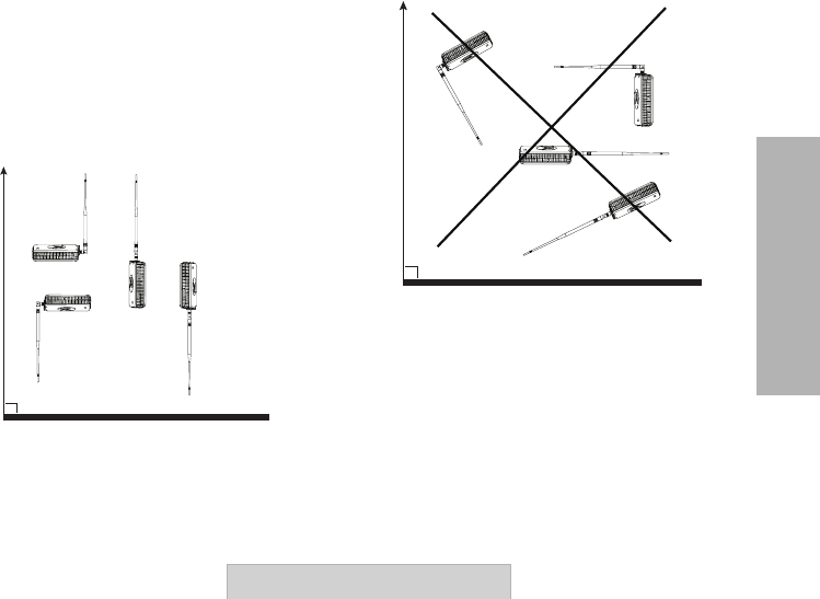
Repeater Positioning and Orientation
Once you have decided the repeater’s location,
make sure you place it either on a flat and stable
surface (outdoors or indoors), lying horizontal as
shown in “Figure 7a. Repeater Orientation on a
Flat Surface” on page 18 and “Figure 7b.
Repeater Orientation Outdoors” on page 18 or
mount it on a flat wall/ceiling surface. The actual orientation of the repeater device itself
shouldn’t have any impact on the repeater’s
performance (given a non-obstructed antenna).
However, when using the dipole antenna (P/N
HKAE4000), make sure the antenna and power
supply are in a straight line (2 to 3 feet minimum)
as shown in “Figure 8a. Repeater Cable Layout
Using Dipole Antenna P/N HKAE4000” on
page 19. When using an external antenna
(Antenna/Magnetic Mount Kit – P/N HKKN4022),
make sure there is a minimum of 2 to 3 feet
distance for both the power cable and RF cable to
Figure 7a. Repeater Orientation on a Flat Surface
Figure 7b. Repeater Orientation Outdoors
REPEATER
INSTALLATION
19
Installation Guide
run straight from the repeater in order to assure
that performance is not deteriorated as shown in
“Figure 8b. Repeater Cable Layout Using External
Antenna P/N HKKN4022” on page 19.
Note: Double check that the Antenna’s cable
doesn’t tangle either around the repeater
device or the power supply. The power
supply cord also shouldn’t tangle around the
repeater device or antenna.
When positioning the repeater, make sure the
repeater antenna is placed away from
obstructions, metal structures or any objects or
enclosures (like elevators) that can cause any
type of shielding.
Power Supply
Cable
2 ft
Figure 8a. Repeater Cable Layout Using Dipole
Antenna P/N HKAE4000
Power Supply
Cable
2 ft
External Antenna
Cable
2 ft
Figure 8b. Repeater Cable Layout Using
External Antenna P/N HKKN4022

20
REPEATER
INSTALLATION
Installation Guide
Antenna Installation Instructions
Repeater antenna installation is critical to the
system performance. The approved Motorola
antenna for the RPU4160 is the UHF Dipole
Antenna P/N HKAE4000, (50 Ohm).
Attaching the Dipole Antenna to
the Repeater
(Installing the dipole antenna directly onto the
repeater is recommended whenever coverage
range or obstructions are not an issue or/and the
repeater is likely to be moved around to other
sites).
1. Align the threaded end of the antenna with
the repeater’s antenna connector and turn
the antenna bushing clockwise to fasten it.
“Figure 9. Attaching Dipole Antenna to the
Repeater (clockwise)” on page 20.
Figure 9. Attaching Dipole Antenna to the
Repeater (clockwise)
REPEATER
INSTALLATION
21
Installation Guide
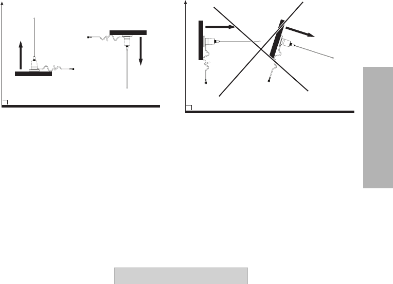
2. Make sure the dipole antenna is mounted
vertically (90 degrees) in reference to earth
ground (either up or down). Please refer to
“Figure 10a. Examples of Correct Dipole
Antenna Orientation” on page 21 and “Figure
10b. Examples of Incorrect Dipole Antenna
Orientation” on page 21 for examples of
incorrect antenna positioning.
Removing the Dipole Antenna
from the Repeater
Turn the antenna bushing counterclockwise until
you can remove it.
Ground
90º
Figure 10a. Examples of Correct Dipole
Antenna Orientation
Ground
90º
Figure 10b. Examples of Incorrect Dipole
Antenna Orientation

22
REPEATER
INSTALLATION
Installation Guide
Installing External Antenna Using the
Antenna/Magnetic Mount /RF Cable Kit
Accessory
If as an outcome of the RF Coverage Test Field,
(please refer to “Pre-Installation Considerations”
on page 10) you decide that you will place the
repeater antenna somewhere else (outdoors or
indoors) away from the repeater device, you
should then use the Antenna/Magnetic Mount and
RF Cable accessory P/N HKKN4022.
Note: Always use Motorola approved accessories
in order to assure performance and safety.
Please refer to “Accessories” on page 59 for
details.
Magnetic Mount Kit Installation
• Ideally the external antenna magnetic mount
should be mounted on a metal surface or
other area with similar material that allows the
mount magnet to stick securely.
• When installing the exterior antenna into the
magnetic mount, make sure the antenna is
always in a vertical orientation (either straight
up or straight down, 90° to ground). Avoid side
or skewed antenna orientations as these
positions can affect repeater performance
(See examples in “Figure 11a. Examples of
Correct Exterior Magnetic Mount Antenna
Orientation” on page 23 and “Figure 11b.
Examples of Incorrect Exterior Magnetic
Mount Antenna Orientation” on page 23).
• Make sure the exterior antenna magnetic
mount is installed and positioned away from
obstructions like metal structures, concrete
walls or any other objects that may cause
signal shielding.
REPEATER
INSTALLATION
23
Installation Guide
Ground
90º
Figure 11a. Examples of Correct Exterior
Magnetic Mount Antenna Orientation
Ground
90º
Figure 11b. Examples of Incorrect Exterior
Magnetic Mount Antenna Orientation
24
REPEATER
INSTALLATION
Installation Guide
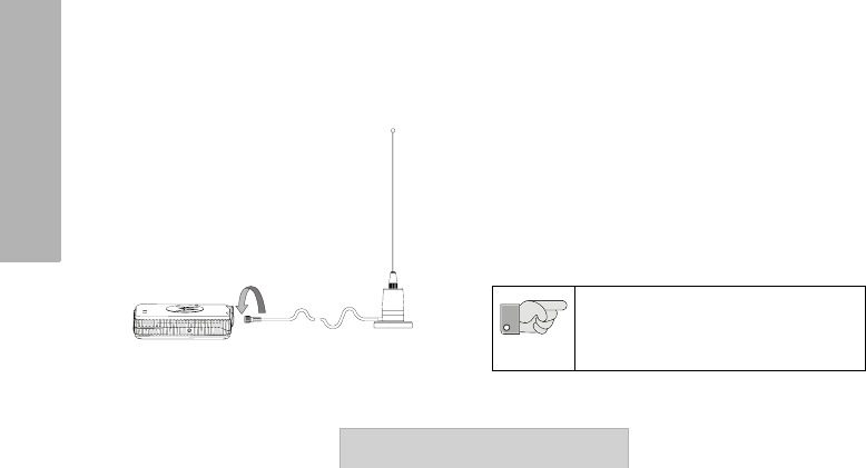
RF Cable Installation
Note: The RF cable is 12 feet long. Keep this in
mind when locating the repeater.
In order to attach the RF Cable to the Repeater
(please refer to “Figure 12. Connecting RF Cable
to Repeater” on page 24), simply:
1. Align the end of the RF Cable antenna
bushing with the repeater’s RF antenna
connector.
2. Turn the RF Cable bushing clockwise to
fasten it.
When installing the RF cable make sure that:
• The RF Cable is taut.
• The RF Cable doesn’t go around the magnetic
mount antenna, antenna, the repeater device
or the power supply cable as all these can
cause electromagnetic interference (please
refer to “Figure 11a. Examples of Correct
Exterior Magnetic Mount Antenna Orientation”
on page 23 and “Figure 11b. Examples of
Incorrect Exterior Magnetic Mount Antenna
Orientation” on page 23 for examples of
wrong positioning).
• If the cable is routed through a ceiling or wall
that connects outdoors, make sure there is an
appropriate sealing around the cable to
prevent water or other material from coming
permanently into the repeater.
Figure 12. Connecting RF Cable to Repeater
Do not attempt to modify the RF cable
from its original design in any way.
Important
REPEATER
INSTALLATION
25
Installation Guide
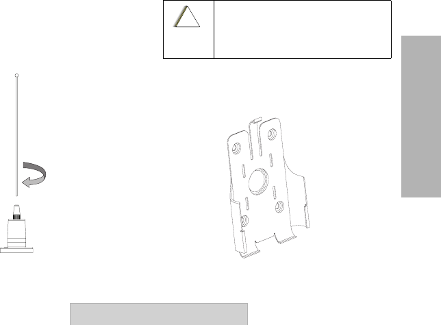
Installing Exterior Antenna
In order to install the exterior antenna into the
magnetic mount, simply:
1. Align the threaded end of the antenna with
the magnetic mount’s mini UHF connector as
shown on “Figure 13. Attaching Exterior
Antenna into Magnetic Mount” on page 25.
2. Turn the antenna clockwise to fasten it.
Uninstalling Exterior Antenna
1. Turn counterclockwise in order to remove
antenna from magnetic mount.
Wall Mount Installation Instructions
The wall mount is recommended for permanent or
semi-permanent indoors repeater installation.
Figure 13. Attaching Exterior Antenna into
Magnetic Mount
It is important that all antenna cables
are grounded at the point they enter
the building.
!
C
a u t i o
n
Figure 14a. Wall Mount Holster
26
REPEATER
INSTALLATION
Installation Guide
To install the wall mount:
1. The wall mount holster is designed to be
capable of mounting to a wall or any other
similar flat surface via screws, straps or
single bolt. (If you choose to use screws,
make sure you secure them tightly on each
one of the wall mount corners).
2. Once the wall mount is firmly secured to a
surface, slide the repeater device from top to
bottom of the holster (“Figure 14b. Installing
the Wall Mount Holster” on page 26) until the
repeater clicks in place into the wall mount
rails.
3. Proceed to connect antenna and power
supply cables.
Remember not to install the repeater on
or near conductive or shielding
surfaces.
Important
Figure 14b. Installing the Wall Mount Holster

REPEATER
INSTALLATION
27
Installation Guide
AC/DC Power Supply Connection
Each repeater ships standard with an AC/DC
Power supply cord (P/N PMPN4002A)(9 feet
long) that connects the repeater to a (110/120)/
(220/240) Vac source.
Nominal Input: (110/120)/(220/240) Vac at
60/50 Hz.
Average output voltage: 12 Vdc with 2.5 Amp (at
maximum load).
To connect AC/DC power supply:
1. Plug the AC/DC power supply into an AC
power source of 110/220 V or a 12 V DC
power and route it to the Repeater Jack
labeled “AC/DC IN”.
Note: The cable from the power supply should be
routed in a straight line and should not
tangle, go around or wrap around the
repeater device, the antenna or the RF
Cable. See “Figure 8a. Repeater Cable
Layout Using Dipole Antenna P/N
HKAE4000” on page 19 (Notice in this
picture that the cable must be laid down
straight for at least 2 feet).
When operating the power supply,
make sure that the maximum input
current never exceeds 0.8 Amp at 100
Vac and ambient temperature is
between -30°C to 60°C.
Provide over voltage/current protection
in order to avoid unsafe operating
conditions.
Important

28
REPEATER
INSTALLATION
Installation Guide
Outdoor Installations Considerations
• The RPX repeaters are suitable for temporary
outdoors operations under environmental
conditions that meet the Mil Specifications 810
and IP55 (designed to meet level of water
ingress and dust protection). For details,
please refer to “Appendix A: Repeater
Specifications” on page 61.
Outdoors Repeater Temporary
Installation – Example
•The repeater outdoors installation example in
“Figure 15a. Outdoors Temporary Repeater
Installation Example” on page 28 shows the
magnetic mount and RF cable installed on top
of the car’s roof in order to secure the antenna
against wind and allow repeater to be placed
inside the car. This is a convenient
configuration as the repeater can be protected
against harsh weather as well as re-charged
directly from the car battery * using vehicle
adaptor P/N HKPN4003, without interrupting
or reducing the repeater power output.
Note: The ideal repeater outdoors usage features
the repeater working on back-up batteries.
(The power supply is not designed for
outdoor use).
Figure 15a. Outdoors Temporary
Repeater Installation Example

REPEATER
INSTALLATION
29
Installation Guide
Vehicle Adaptor
The repeaters offer the convenience of a
Vehicle Adaptor accessory (P/N HKPN4003,
sold separately) for the repeaters.
Figure 15b. Vehicle Adaptor
30
ALKALINE BATTERY
FRAME
Installation Guide
ALKALINE BATTERY FRAME
ABOUT ALKALINE BATTERIES
Please visit your Alkaline batteries’
manufacturer website for information and
guidelines regarding handling and disposal of
Alkaline batteries.
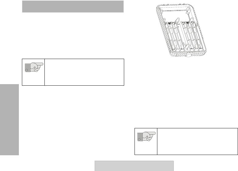
Alkaline Batteries Frame Solution
The repeaters’ standard package comes equipped
with an Alkaline Battery Frame Solution, (“Figure 16a.
Alkaline Battery Frame” on page 30 – alkaline
batteries are not included).
When the repeater is using the Alkaline batteries as
the backup power in the event of an AC/DC power
absence or failure and there is an AC/DC power
failure or absence, the repeater automatically
switches to back-up mode from the alkaline batteries.
Alkaline Battery Life Estimation
When the repeater is working on back-up alkaline
batteries, the estimated battery life time (assumed
fully charged) is 16 hours for both 2 W and 4 W
models.
Whenever the 4 W repeater is switched to work
on battery back-up, the system will only
transmit at 2 W.
Do not store alkaline batteries in a non-
operating equipment for longer than 30
days.
Important
The 4 W repeater will automatically
switch to 2 W output power whenever it
detects that there is no AC/DC input. It
will then operate on back-up battery.
Important
Figure 16a. Alkaline Battery Frame
ALKALINE BATTERY
FRAME
31
Installation Guide
Alkaline Battery Power LED (Side LED)
Note: Alkaline Battery Frame is also available as a
stand-alone accessory (P/N HKHN4003).
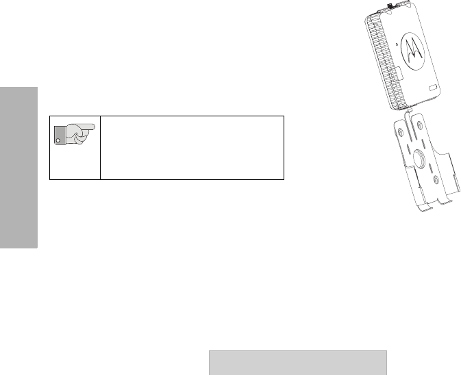
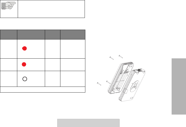
Installing/Removing the Alkaline
Battery Frame
1. Turn OFF the repeater if it is turned ON.
2. Disconnect AC/DC Power.
3. Use a Phillips screwdriver to remove the four
corner screws located at each corner on the
back of the repeater, disconnect power
harness and lift away the repeater back
battery frame. “Figure 16b: Installing the
Alkaline Battery Frame into/from the
Repeater” on page 31.
Do not attempt to recharge alkaline
batteries. They are non-rechargable.
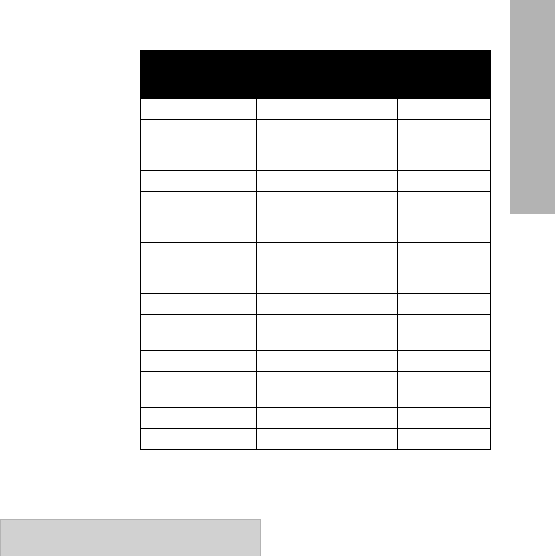
Table 3: Repeater Alkaline Frame Power LED (Side)
Status LED Status AC/DC
Status Comments
No
Batteries
Detected CX
When the
battery frame is
empty or the
batteries are
dead
Batteries
Detected CX Batteries are
good and in
place
OFF DX
When AC/DC is
disconnected,
the LEDs will
be OFF
CX: Connected to AC/DC DX: Disconnected from AC/DC
Important
R
e
d
(Slow)
Blinking
Steady
Red
OFF
Figure 16b: Installing the Alkaline Battery
Frame into/from the Repeater
32
ALKALINE BATTERY
FRAME
Installation Guide
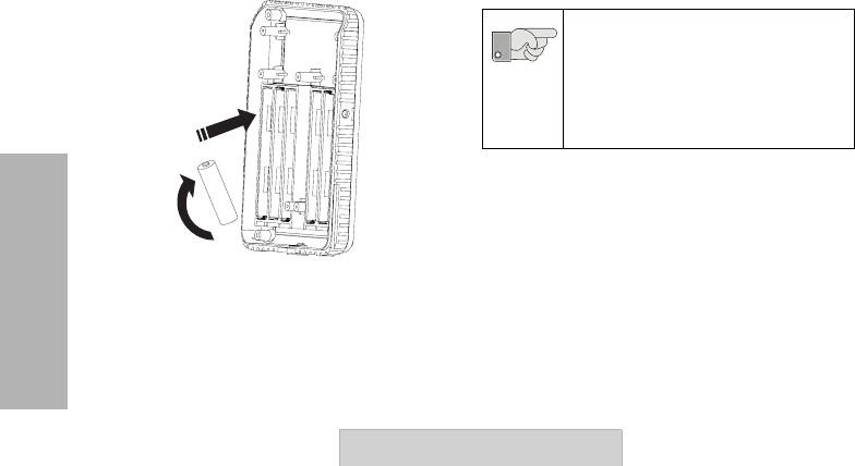
4. Arrange alkaline batteries to match each of
the alkaline frame batteries’ polarity (+ or -)
markings and slide them into each one of the
alkaline battery frame compartments. Repeat
until 12 batteries have been properly placed.
Plug in the power harness. “Figure 16c:
Installing the Alkaline Batteries” on page 32.
5. Make sure the repeater’s internal cable is
connected between the repeater and the
battery frame.
6. Assemble the alkaline battery frame (loaded
with the alkaline batteries) into the back of
the repeater by tightening securely the four
screws on each of the four corners on the
back of the repeater. Please refer to “Figure
16b: Installing the Alkaline Battery Frame
into/from the Repeater” on page 31.
LI-ION BATTERY FRAME (OPTIONAL
ACCESSORY)
The repeaters are capable of operating with Li-Ion
batteries. The Li-Ion Battery Frame, P/N
HKHN4004 is sold separately as an accessory.
1
2
Figure 16c: Installing the Alkaline Batteries
When securing back the alkaline frame
lid into the repeater, it is very important
to make sure the screws are tightened
firmly to preserve the sealing of your
repeater. Failing to do so can negatively
impact the repeater’s IP55 water and
dust resistant feature.
Important
33
GETTING STARTED
User Guide
GETTING STARTED
TURNING REPEATER ON/OFF
1. Turn the ON/OFF knob clockwise to turn on
the repeater. The repeater front LED will
blink a red light for 3 seconds.
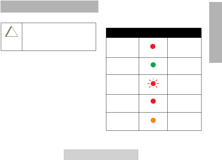
REPEATER STATUS LED (FRONT LED)
Table 4 "Repeater Status LED Indicator (Front
LED) " on page 33 shows the repeater LED status
summary:
Radio LED Indicators
Never transmit without having a
transmit antenna connected to the TX
antenna jack of the repeater.
!
C
a u t i o
n
Table 4: Repeater Status LED Indicator
(Front LED)
MODE LED STATUS
Transmit Solid Red
Receive (RX) Solid Green
Idle Red (Slow)
Blinking
Power Up Solid Red 2 – 3
seconds
Transmit Low
Power Solid Orange

GETTING STARTED
34 User Guide
Low Battery
Shutdown Orange (Fast)
Blinking
Low Battery Orange Blinking
Fatal Error at
Power Up
1 Green Blink, 1
Orange Blink, 1
Green Blink,
then repeat
Unprogrammed
Channel Double Red
(Slow) Blinking
Non-Repeater
Channel Mode
1 Red Blink, 1
Green Blink,
then repeat
Table 4: Repeater Status LED Indicator
(Front LED) (Continued)
MODE LED STATUS

35
GETTING STARTED
User Guide
SELECTING A CHANNEL
The repeaters offer 16 different channels from
which you can choose ONE channel at a time for
the repeater to operate. To select a channel, rotate
the Channel Selector Knob until you reach the
desired channel. Each channel has its own pre-
programmed Frequency, Interference Eliminator
Code and Bandwidth Settings. Please refer to the
following table for factory default values details:
Table 5: Repeater Channels Default Settings
Channel
#
Transmit Band
450 – 455 Mhz Common Parameters Receive Band
465 – 470 Mhz–
Frequency
(TX) Index # Frequency
(TX) Mhz Code
(Index #)
Code
Value
(Hz) Bandwidth Frequency
(RX) Index
#
Frequency
(RX) Mhz
1 65 451.1875 167 12.5 KHz 34 466.0375
2 66 451.2375 477 12.5 KHz 35 466.0625
3 67 451.2875 888.5 12.5 KHz 36 466.0875
4 68 451.3375 29 179.9 12.5 KHz 37 466.1125
5 69 451.4375 0none 12.5 KHz 38 466.1375
6 70 451.5375 167 12.5 KHz 39 466.1625
7 71 451.6375 682.5 12.5 KHz 40 466.1875
8 72 452.3125 10 94.8 12.5 KHz 41 466.2125

GETTING STARTED
36 User Guide
In order to modify these default values, you should use the CPS Software. Please refer to "Programming
The Repeater" on page 38 for more details.
9 74 452.4125 29 179.9 12.5 KHz 42 466.2375
10 75 452.5125 0 0 12.5 KHz 50 467.8625
11 76 452.7625 374.4 12.5 KHz 51 467.8875
12 77 452.8625 579.7 12.5 KHz 52 467.9125
13 65 451.1875 785.4 12.5 KHz 53 469.4875
14 66 451.2375 991.5 12.5 KHz 54 469.5125
15 72 451.3125 11 97.4 12.5 KHz 55 469.5375
16 74 452.4125 13 103.5 12.5 KHz 56 469.5625
Table 5: Repeater Channels Default Settings (Continued)
Channel
#
Transmit Band
450 – 455 Mhz Common Parameters Receive Band
465 – 470 Mhz–
Frequency
(TX) Index # Frequency
(TX) Mhz Code
(Index #)
Code
Value
(Hz) Bandwidth Frequency
(RX) Index
#
Frequency
(RX) Mhz
37
GETTING STARTED
User Guide
REPEATER PROGRAMMING DEFAULT
VALUES
"Programmable Features Default Values" on
page 37 shows the default factory values that the
repeater has pre-programmed. These values can
only be customized by using the CPS software.
Table 6: Programmable Features Default Values
Repeater Features Default Values
Feature Values Default
TX Timeout 1, 2 or 3 minutes 1 minute
TX Hangtime
(or Carrier
Delay) Off to 50 seconds 5 seconds
Courtesy Beep ON or OFF OFF
Repeater ID 15 minutes, 30
minutes, after TX
hangtime, or OFF 15 minutes
On Battery
Back-Up
OFF, 15 minutes, 30
minutes, 45
minutes, 60 minutes 30 minutes
Low Battery TX 0 to 255 minutes 10 minutes
Number of
Channels 1 to 16 16
Reverse Burst 180 to 240 180
TX Power Low (2 W) or High
(4 W) High – 4 W
TX BW 12.5 or 25.0 KHz 12.5 KHz
RX BW 12.5 or 25.0 Khz 12.5 KHz

PROGRAMMING THE
REPEATER
38 User Guide
PROGRAMMING THE
REPEATER
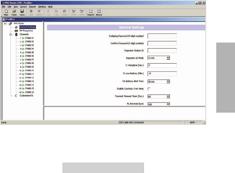
PROGRAMMING FEATURES
OVERVIEW
The repeaters are fully programmable devices that
provide features customization by using the CPS*
(Computer Programming Software).
The CPS allows to program frequencies and
Codes (either from a pre-loaded frequency default
list table or allowing to enter directly any
customized value) as well as other features such
as Bandwidth, Hang Time-out, Repeater ID Timer,
Courtesy Beep timer, Transmit Time Out Timer,
Reverse Burst, among others.
One of the key advantages of the CPS is the
flexibility to quickly and easily program and clone
several repeaters using a customized profile. The
CPS also provides security by giving the option to
set up a codeplug password for profile repeater's
management (CPS Manager Lock).
Please refer to the CPS software HELP File
(under “Content and Index”) where you will find
the details and explanations for each one of the
repeater’s programmable features.
PROGRAMMING THE
REPEATER
39
User Guide
Note: Contact your Motorola distributor or reseller in order to get information on how to get a copy of the CPS software.
Figure 17. Example of the CPS Repeater Interface
PROGRAMMING THE
REPEATER
40 User Guide
Programming the Repeater Using the
CPS
Before you begin programming the repeater make
sure you have available:
• A PC ( Windows® XP, Windows 2000 compatible,
Vista)
• CPS Programming Cable (sold separately as an
accessory P/N RKN4155),
• CPS* Software installed
• Repeater batteries are charged or repeater is
connected to a AC/DC power line.
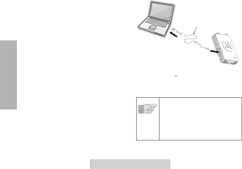
Please notice that this CPS
Programming cable’s mini-
connector should not be used for
connecting devices other than the
RDX Series chargers (RLN6304/
RLN6375) and the repeaters.
RPX
CPS Software
To computer
USB Port
To repeater
programming
connector
CPS Programming
Cable
Figure 18. Programming the Repeater
Using the CPS
Important

PROGRAMMING THE
REPEATER
41
User Guide
How to Read and Modify Your
Repeater’s Features
1. Ensure you have installed the latest CPS in
your computer.
2. Turn the repeater OFF.
3. Plug the CPS Programming Cable P/N
RKN4155 into the Repeater’s programming
connector. “Figure 18. Programming the
Repeater Using the CPS” on page 40.
4. Connect the other end of the CPS cable into
your computer ‘s USB port.
5. Open your CPS software and turn your
repeater ON.
6. Click “read” icon in the upper bar menu.
Note: The “read” icon is grayed-out until the
computer detects the CPS Programming
Cable.
7. When the CPS reads the repeater
successfully, you will see a window pop up
showing a bar progress icon indicating the
repeater’s profile is being read.
Note: You will now be able to read and modify all
your repeater features with the options
available in the left side menu in your profile
window . For more details on how to read,
write or modify radio features, please refer
to the CPS Help Menu –> Content and
Index. Detailed information about how to
clone the repeater’s profile is also available
in the CPS Help Menu –> Content and
Index –> Cloning Repeaters.

PROGRAMMING THE
REPEATER
42 User Guide
CPS Connection Trouble Shooting
Table 7: Programming Mode: Trouble Shooting
Symptom Try This
CPS doesn’t read the
repeater or write to the
repeater
Make sure the CPS cable is securely connected on both ends
(programming port in the repeater and USB port in the computer)/Make sure
your repeater hasn’t run out completely of battery power or is connected to
an AC/DC supply/Make sure the CPS cable is not damaged.
CPS displays “Error:
Communication Error”
when trying to read or
write to the repeater
Make sure your repeater is ON/Double check that the repeater model
matches your CPS version and region as they should be compatible in order
to read and write. For checking your CPS version, click in the “about” icon in
the upper tool bar.
CPS displays “your
repeater doesn’t match
your region”
Double check that the radio model matches your CPS version and region as
they should be compatible in order to read or write. For checking your CPS
version, click on the “about” icon in the upper tool bar.
When trying to clone
the repeater, the CPS
displays an error or the
cloning fails
Please refer to “Cloning Repeaters” in the CPS Help File for details on
cloning details.

PROGRAMMING YOUR
RADIOS
43
User Guide
PROGRAMMING YOUR
RADIOS
PROGRAMMING YOUR RDX 4 W
RADIOS TO WORK WITH THE
REPEATERS
RDX 4 W series radios are fully compatible with
your repeaters as they are of the same UHF band
and they support repeater capability features.
However, in order to configure the radios to
communicate with the repeater, there are basic
tips that you should take into account:
PROGRAMMING YOUR
RADIOS
44 User Guide
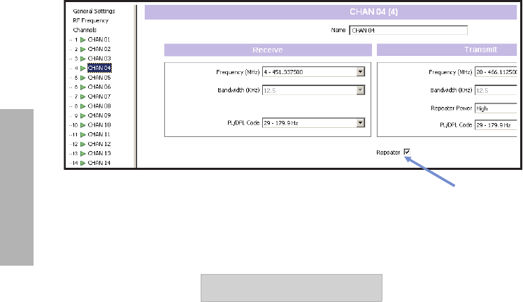
• Make sure the channels in both the RDX radios and the repeaters that you want to use with the
repeater capability are actually enabled in the CPS with a “check” box looking as follows:
Figure 19. Enabling Repeater capability settings

PROGRAMMING YOUR
RADIOS
45
User Guide
• Make sure the TX frequency and PL Code in
the radio channel that has been chosen for
repeater, is the same as the RX frequency in
the repeaters. Same for the RX frequency in
your RDX radio: make sure it matches the TX
frequency and PL code in the repeaters
channel.
• The repeaters have 16 channels available,
each one with two TX/RX frequency pairs.
You can either use the repeater default
programmed frequencies and customize the
RDX channels to match the repeater’s or you
can customize the repeater frequencies to
different frequencies pairs to match frequency
in the RDX radios.
Note: Take into account that when matching
channel frequencies between the repeater
and the radios, you must also need to make
sure all other channel parameters (i.e.
codes, bandwidth and reverse burst) are at
the same correspondent values in order for
the radios-repeater communications to take
place properly.
REPEATER CLONING
46 User Guide
REPEATER CLONING
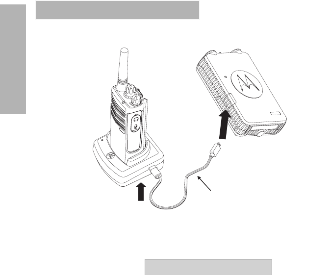
RDX RADIO TO REPEATER CLONING
To repeater
programming connector
To RDX radio
charger mini-port
R2R Cloning Cable
Figure 20. Cloning from an RDX radio into the Repeater

REPEATER CLONING
47
User Guide
OPERATING INSTRUCTIONS
Below are instructions on how to clone your RDX
2 W / 4 W radio into one of the repeaters.
Note: It is NOT possible to clone the repeaters into
the RDX radio.
The only parameters that can be cloned into the
Repeater are:
• channel frequency,
• code,
• bandwidth,
•power,
• reverse burst,
• scan list
• the number of channels.
Before you start the cloning process, make sure
you have the following components:
• Fully charged batteries on both the RDX radio
and one of the repeaters
• One Single Unit Chargers (SUC) for the RDX
Radio (either P/N RLN6304 or RLN6175)
• An RDX Radio to Radio (R2R) Cloning Cable
P/N RLN6303
• An RDX Radio, repeater capable
CLONING INSTRUCTIONS
1. Turn OFF both the radio and the repeater.
2. Unplug any cables (power supply or USB
cables) from the Single Unit Charger.
3. Plug one side of the cloning cable mini
connector to the Single Unit Charger. Plug
the other end to the Repeater programming
port connector.
Note: During the cloning process, no power is
being applied to the Single Unit Charger.
The batteries will not be charged. A data
communication is being established
between the repeater and the radio.
4. Turn ON the repeater.
5. Power up the RDX radio following the
sequence below:
• Long press the PTT button and SB2
simultaneously while turning the radio ON.
• Wait for 3 seconds before releasing the buttons
until a distinctive audible tone is heard.
REPEATER CLONING
48 User Guide
Note: After cloning is completed, the RDX radio
will sound either a “pass” tone (cloning was
successful) or a “fail” tone (cloning process
has failed). The “pass” tone sounds like a
good key “chirp” whereas the “fail” tone
sounds similar to a “bonk” tone. If the RDX
radio is a display model, it will either show
“Pass” or “Fail” on the display (a tone will be
heard within 5 seconds).
6. Once you have completed the cloning
process, turn the RDX radio OFF and ON to
exit ‘clone’ mode.
7. Turn the repeater OFF and ON to exit “clone”
mode.
- If the RDX channels contains
frequencies that are not
within the repeater TX or RX
frequency range, the
repeater will not work on
these channels.
- In the RDX radio, make sure
that in each one of the TX/
RX frequency pairs, the
bandwidth setting has
exactly the same value. For
example, if in Channel 7 the
TX bandwidth separation is
12.5 KHz, then the
corresponding RX
bandwidth separation in this
same channel 7 should be
also 12.5 KHz.
Important

REPEATER CLONING
49
User Guide
WHAT TO DO IF CLONING FAILS
The radio will emit an audible “bonk” indicating
that the cloning process has failed. In the event
that cloning fails, try performing each of the
following tests before trying to start the cloning
process again:
1. Ensure that the batteries on both radio and
repeater are fully charged.
2. Check the cloning cable connection on both
ends.
3. Ensure that the battery is engaged properly
on to the RDX radio.
4. Ensure that the RDX radio is in cloning
mode.
5. Ensure that the repeater is turned ON.

TROUBLESHOOTING
50 User Guide
TROUBLESHOOTING
Symptom Try This...
No Power
Recharge or replace the Li-Ion battery. Replace AA batteries.
Reposition or replace AA batteries. Extreme operating
temperatures may affect battery life.
Verify repeater is connected to AC/DC.
Limited Talk Range
Steel and/or concrete structures, heavy foliage, buildings or
vehicles decrease range. Check for clear line of sight to improve
transmission. Verify repeaters and radios are correctly programed.
Transmissions are noisy
and not clear
Make sure the radios are set up to 12.5 KHz bandwidth. Repeater
is not fully compatible with radios using companding or set up at 25
KHz bandwidth.

TROUBLESHOOTING
51
User Guide
Message Are Not Received
Confirm that the radios have the same Channel, Frequency,
Interference Eliminator Code and Scramble Code settings and are
consistent with the Repeater’s settings. Verify the range coverage
is appropriate and there are no obstacles or shielding.
Heavy Static or
Interference
Radios are too close to repeater; they must be at least five feet
apart. Radios are too far apart from the repeater’s antenna. Double
check to make sure there are no obstacles interfering with
Low Batteries Recharge or replace Li-Ion battery. Replace AA batteries. Extreme
operating temperatures affect battery life.
Li-On Power LED Light
Does Not Come On
Check if repeater’s batteries are properly inserted and/or check
battery/charger contacts to be sure they are clean and charging pin
is inserted correctly.
Low Battery LED Blinking
Although New Batteries
Are Installed
Verify that the radio is set to the correct battery type and is well
positioned into the battery frame according to instructions.
Symptom Try This... (Continued)

TROUBLESHOOTING
52 User Guide
Repeater Can’t Receive or
Can’t Re-transmit/Radio
Can Transmit But Can’t
Receive
Check repeater’s programming settings versus radio’s settings.
Battery Does Not Charge
Although It Has Been
Placed in the Li-On Battery
Frame For A While
Check if the repeater is connected to the AC/DC power and is
getting appropriate power. Check the charger LED indicators.
Change the Li-ON batteries using an external charger to see if the
batteries are damaged. Make sure the operating temperatures are
within specific ranges.
Note:
The RPX Repeater Series™ are designed with a companding feature that is compatible with Motorola 2-
way Business Radios. If you're working with a different radio and you experience static or noise in your
communications, double check that the radios are capable of companding.
Symptom Try This... (Continued)
USE AND CARE
53
User Guide
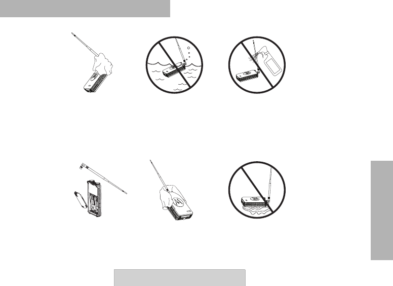
USE AND CARE
Use a soft damp cloth
to clean the exterior Do not immerse
in water Do not use alcohol or
cleaning solutions
Turn repeater OFF
and remove batteries
and antenna
Dry with soft cloth Do not use repeater
until completely dry
If the repeater is submerged in water...

WARRANTY
54 User Guide
MOTOROLA LIMITED
WARRANTY FOR THE
UNITED STATES AND
CANADA
What Does this Warranty Cover?
Subject to the exclusions contained below,
Motorola, Inc. warrants its telephones, pagers, and
consumer and business two-way radios (excluding
commercial, government or industrial radios) that
operate via Family Radio Service or General
Mobile Radio Service, Motorola-branded or
certified accessories sold for use with these
Products (“Accessories”) and Motorola software
contained on CD-ROMs or other tangible media
and sold for use with these Products (“Software”)
to be free from defects in materials and
workmanship under normal consumer usage for
the period(s) outlined below.
This limited warranty is a consumer's exclusive
remedy, and applies as follows to new Motorola
Products, Accessories and Software purchased by
consumers in the United States, which are
accompanied by this written warranty.
Products and Accessories
Products Covered Length of Coverage
Products and
Accessories as
defined above, unless
otherwise provided for
below.
One (1) year from the date
of purchase by the first
consumer purchaser of the
product unless otherwise
provided for below.
Decorative
Accessories and
Cases.
Decorative covers,
bezels, PhoneWrap™
covers and cases.
Limited lifetime warranty
for the lifetime of
ownership by the first
consumer purchaser of the
product.
Business Two-way
Radio Accessories
One (1) year from the date
of purchase by the first
consumer purchaser of the
product.
Products and
Accessories that are
Repaired or
Replaced.
The balance of the
original warranty or for
ninety (90) days from the
date returned to the
consumer, whichever is
longer.

WARRANTY
55
User Guide
Exclusions
Normal Wear and Tear. Periodic maintenance,
repair and replacement of parts due to normal
wear and tear are excluded from coverage.
Batteries. Only batteries whose fully charged
capacity falls below 80% of their rated capacity
and batteries that leak are covered by this limited
warranty.
Abuse & Misuse. Defects or damage that result
from: (a) improper operation, storage, misuse or
abuse, accident or neglect, such as physical
damage (cracks, scratches, etc.) to the surface of
the product resulting from misuse; (b) contact with
liquid, water, rain, extreme humidity or heavy
perspiration, sand, dirt or the like, extreme heat, or
food; (c) use of the Products or Accessories for
commercial purposes or subjecting the Product or
Accessory to abnormal usage or conditions; or (d)
other acts which are not the fault of Motorola, are
excluded from coverage.
Use of Non-Motorola Products and
Accessories. Defects or damage that result from
the use of Non-Motorola branded or certified
Products, Accessories, Software or other
peripheral equipment are excluded from coverage.
Unauthorized Service or Modification. Defects
or damages resulting from service, testing,
adjustment, installation, maintenance, alteration,
or modification in any way by someone other than
Motorola, or its authorized service centers, are
excluded from coverage.
Altered Products. Products or Accessories with
(a) serial numbers or date tags that have been
removed, altered or obliterated; (b) broken seals
or that show evidence of tampering; (c)
mismatched board serial numbers; or (d)
nonconforming or non-Motorola housings, or
parts, are excluded form coverage.

WARRANTY
56 User Guide
Communication Services. Defects, damages, or
the failure of Products, Accessories or Software
due to any communication service or signal you
may subscribe to or use with the Products
Accessories or Software is excluded from
coverage.
Software
Exclusions
Software Embodied in Physical Media. No
warranty is made that the software will meet your
requirements or will work in combination with any
hardware or software applications provided by
third parties, that the operation of the software
products will be uninterrupted or error free, or that
all defects in the software products will be
corrected.
Software NOT Embodied in Physical Media.
Software that is not embodied in physical media
(e.g. software that is downloaded from the
internet), is provided “as is” and without warranty.
WHO IS COVERED?
This warranty extends only to the first consumer
purchaser, and is not transferable.
WHAT WE WILL DO TO CORRECT
WARRANTY PROBLEMS
At no charge to you, we have the option to repair
or replace the Products or software that do not
conform to the warranty, or to refund the Products’
purchase price. We may use functionally
equivalent reconditioned/refurbished/pre-owned or
new Products or parts. No software updates are
provided.
HOW TO OBTAIN WARRANTY SERVICE OR
OTHER INFORMATION?
Contact your Motorola point of purchase.
Please call:
1-800-448- 6686 in the USA
1-800-461-4575 in Canada
1-866-522-5210 on your TTY (Text Telephone)
Products Covered Length of Coverage
Software. Applies only
to physical defects in
the media that
embodies the copy of
the software (e.g. CD-
ROM, or floppy disk).
Ninety (90) days from the
date of purchase.

WARRANTY
57
User Guide
You will receive instructions on how to ship the
Products to Motorola. You must ship the Products
to us with freight, duties and insurance prepaid.
Along with the Products you must include:
(a) a copy of your receipt, bill of sale or other
comparable proof of purchase;
(b) a written description of the problem;
(c) the name of your service provider (if this
Product requires subscription service);
(d) the name and location of the installation facility
(if applicable) and, most importantly;
(e) your address and telephone number. If
requested, you must also return all detachable
parts such as antennas, batteries and chargers.
RETAIN YOUR ORIGINAL PROOF OF
PURCHASE.
We will ship repaired or replacement Products at
our expense for the freight and insurance, but at
your expense for any duties. If additional
information is needed, please contact us at the
telephone number listed above.
SOFTWARE COPYRIGHT NOTICE
The Motorola products described in this manual
may include copyrighted Motorola and third party
software stored in semiconductor memories or
other media. Laws in the United States and other
countries preserve for Motorola and third party
software providers certain exclusive rights for
copyrighted software, such as the exclusive rights
to distribute or reproduce the copyrighted
software. Accordingly, any copyrighted software
contained in the Motorola products may not be
modified, reverse-engineered, distributed, or
reproduced in any manner to the extent allowed by
law.
Furthermore, the purchase of the Motorola
products shall not be deemed to grant either
directly or by implication, estoppel, or otherwise,
any license under the copyrights, patents, or
patent applications of Motorola or any third party
software provider, except for the normal, non-
exclusive, royalty-free license to use that arises by
operation of law in the sale of a product.

WARRANTY
58 User Guide
PATENT NOTICE
This product is covered by one or more of the
following United States patents.
5896277 5894292 5864752 5699006 5742484
D408396 D399821 D387758 D389158 5894592
5893027 5789098 5734975 5861850 D395882
D383745 D389827 D389139 5929825 5926514
5953640 6071640 D413022 D416252 D416893
D433001
EXPORT LAW ASSURANCES
This product is controlled under the export
regulations of the United States of America. The
Governments of the United States of America may
restrict the exportation or re-exportation of this
product to certain destinations. For further
information contact the U.S. Department of
Commerce.
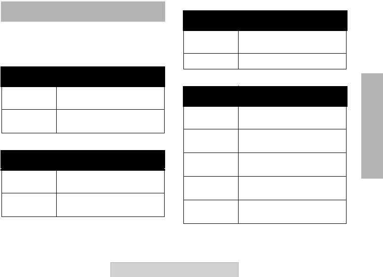
ACCESSORIES
59
User Guide
ACCESSORIES
RPX REPEATER SERIES
ACCESSORIES
ANTENNA ACCESSORIES
BATTERIES ACCESSORIES
POWER SUPPLIES ACCESSORIES
BATTERY ACCESSORIES
Part No. Description
HKKN4022A Antenna with MAG Mount & 12
foot RF Cable Kit
HKAE4000A Dipole Antenna 438 – 470 MHz
Kit
Part No. Description
HKHN4003A RPX Repeater Series™
Alkaline Battery Frame
HKHM4004A RPX Repeater Series™ Li-On
Battery Frame
Part No. Description
HKPN4003A Cigarette Lighter Vehicle
Adaptor
TBD AC/DC Repeater Power Supply
Part No. Description
RLN6305 High Capacity Li-Ion Battery
2200 mAh
RLN6308 Ultra High Capacity Li-Ion
Battery 2400 mAh
RLN6351 Standard Li-Ion Battery
1100 mAh
HKNN4010A Ultra High Capacity Li-Ion
Battery CR Kit
HKKN4011A High Capacity Li-Ion Battery CR
Kit

ACCESSORIES
60 User Guide
RDX PICK-UP RADIOS AND
ACCESSORIES
CABLES ACCESSORIES
CHARGER ACCESSORIES
2-WAY RDX REPEATER CAPABLE UHF
RADIOS
Part No. Description
RLN6303 Radio to Radio Cloning Cable
RKN4155 CPS USB Programming Cable
Part No. Description
RLN6304 Rapid Charger Kit
RLN6309 Multi-Unit Charger (MUC) Kit
RLN6175 Standard Drop-in Tray Charger
Note: For charging RDX radios and
stand-alone Li-Ion batteries only.
Part No. Description
RDU4160d RDX UHF 4 W CH 2-Way Radio
RDU4100 RDX UHF 4 W CH 2-Way Radio

61
APPENDIX A: REPEATER
SPECIFICATIONS
User Guide
APPENDIX A: REPEATER
SPECIFICATIONS
Product Specifications UHF 25 KHz UHF 12.5 KHz
FCC Id TBD TBD
IC Id TBD TBD
FCC Parts Place Holder TBD
Emission Designators 14K8F3E 11K1F3E
Operating RF Band (MHz) 450 – 470 450 – 470
Frequency Separation 10 – 20 MHz
(Programmable) 10 – 20 MHz
(Programmable)
TX Frequency Band 450 – 455 Mhz 450 – 455 Mhz
RX Frequency Band 465 – 470 Mhz 465 – 470 Mhz
Channel Spacing (narrow and wide band) 25 KHz 12.5 KHz
Mode of Operation Duplex Duplex
Code Signalling Morse Code Morse Code
Number of Operating Channels 1 (TX/RX) Channel 1 (TX/RX) Channel
Number of Software Programmable Channels/
Knob Channels 16 16
Synthesized Steps 1 Hz 1 Hz
Tone/Code Signalling Morse Code Morse Code
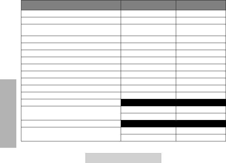
APPENDIX A: REPEATER
SPECIFICATIONS
62 User Guide
Carrier Power Output (AC/DC) (Model Dependant) 2 W/4 W 2 W/4 W
Carrier Power Output on Batteries 2 W 2 W
Hang-Time Timer From 0 (OFF) to 50
seconds programmed From 0 (OFF) to 50
seconds programmed
Time-Out Timer 1, 2 or 3 minutes 1, 2 or 3 minutes
RF Connector MIni UHF MIni UHF
Cigarette Lighter Connector (Vehicle Adaptor) Yes Yes
Antenna Impedance 50 Ohms 50 Ohms
Duty Cycle 100% 100%
PL Codes 39+ Programmable 39+ Programmable
DPL Codes 84 84
Input Voltage -– Repeater 110/220 Vac +/- 10% 110/220 Vac +/- 10%
Input Voltage -– Transceiver 12 Vdc +/- 10% 12 Vdc +/- 10%
Input Current Repeater (@100 Vac)
TX/RX
Standby 230 mA 230 mA
30 mA 30 mA
Input Current Transceiver (@ 12 Vdc)
TX/RX
Standby 1.6 A 1.6 A
200 mA 200 mA
Product Specifications UHF 25 KHz UHF 12.5 KHz
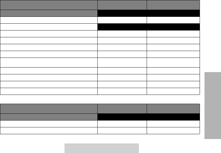
63
APPENDIX A: REPEATER
SPECIFICATIONS
User Guide
Product Specifications UHF 25 KHz UHF 12.5 KHz
Transmitter
Frequency Range (MHz) 450 – 455 Mhz 450 – 455 Mhz
Carrier RF Output
High 4.0 W 4.0 W
Low 2.0 W 2.0 W
Frequency Stability +/- 1.0 PPM (-300°C – 600°C) +/- 1.0 PPM (-300°C – 600°C)
Modulation Direct FM Direct FM
Deviation (Modulation Limiting) ± 5.0 kHz ± 5.0 kHz
Spurs & Harmonies (dBm) < - 20 dBm < -13 dBm
FM Hum & Noise - 50 dB - 50 dB
Adjacent Channel Power 60 dBc 60 dBc
Radiated Spurious Emissions < - 20 dBm < -13 dBm
Product Specifications UHF 25 KHz UHF 12.5 KHz
Receiver
Frequency Range (MHz) 465 – 470 Mhz 465 – 470 Mhz
Receiving System Programable Programable
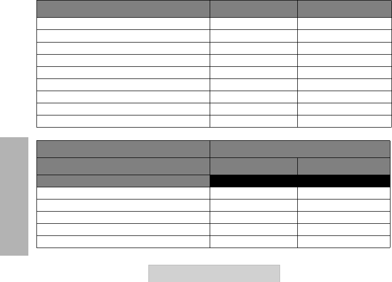
APPENDIX A: REPEATER
SPECIFICATIONS
64 User Guide
Frequency Stability +/- 1.0 PPM (-300°C – 600°C) +/- 1.0 PPM (-300°C – 600°C)
Audio Frequency 300 Hz to 3 Khz 300 Hz to 3 Khz
Sensitivity (12 dB SINAD) - 119 dBm (0.25 uV) - 119 dBm (0.25 uV)
Selectivity (Adjacent Channel Selectivity) - 75 dB - 70 dB
Intermodulation Rejection - 70 dB - 70 dB
Spurious Response Rejection (blocking 1 Mhz) - 90 dB - 90 dB
Radiated Spurious Emissions (< 1 GHz) - 54 dBm - 54 dBm
Radiated Spurious Emissions (< 1 GHz) - 52 dBm - 52 dBm
Input impedance 50 Ohms 50 Ohms
Product Specifications UHF 25 KHz UHF 12.5 KHz
810 Military Standards (1) RPX Repeater 4 W –UHF 450 – 470 MHz
METHOD PROCEDURE
810 - C
Low Pressure 500.1 1
High Temperature 501.1 1, 2
Low Temperature 502.1 1
Temperature Shock 503.1 1
Solar Radiation 505.1 1
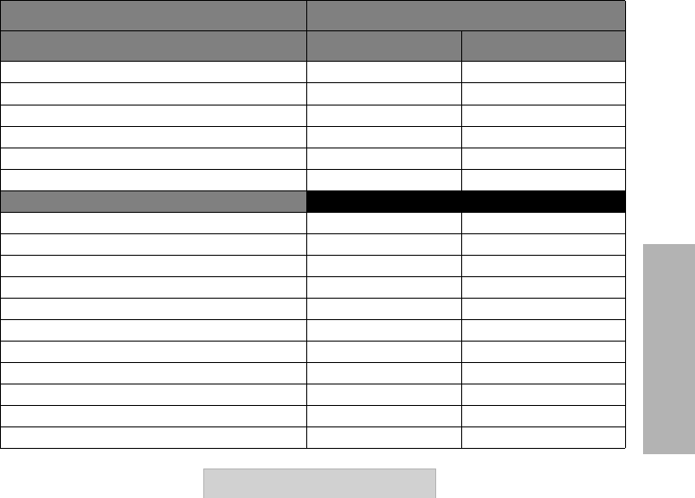
65
APPENDIX A: REPEATER
SPECIFICATIONS
User Guide
Rain 506.1 1, 2
Humidity 507.1 2
Salt Fog 509.1 1
Dust 510.1 1
Vibration 514.1 8, 10
Shock 516.1 1, 2, 5
810 - D
Low Pressure 500.2 2
High Temperature 501.2 1, 2
Low Temperature 502.2 1, 2
Temperature Shock 503.2 1
Solar Radiation 505.2 1
Rain 506.2 1, 2
Humidity 507.2 2, 3
Salt Fog 509.2 1
Dust 510.2 1
Vibration 514.3 1
Shock 516.3 1, 4
810 Military Standards (1) RPX Repeater 4 W –UHF 450 – 470 MHz
METHOD PROCEDURE
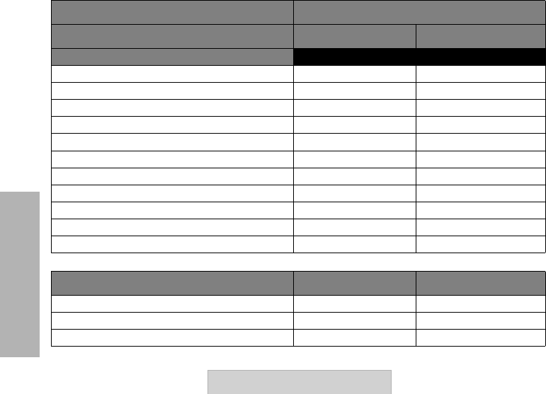
APPENDIX A: REPEATER
SPECIFICATIONS
66 User Guide
810 - E
Low Pressure 500.3 2
High Temperature 501.3 1, 2
Low Temperature 502.3 1, 2
Temperature Shock 503.3 1
Solar Radiation 505.3 1
Rain 506.3 1, 2
Humidity 507.3 2, 3
Salt Fog 509.3 1
Dust 510.3 1
Vibration 514.4 1
Shock 516.4 1, 4
810 Military Standards (1) RPX Repeater 4 W –UHF 450 – 470 MHz
METHOD PROCEDURE
Other Product Specifications UHF 25 KHz UHF 12.5 KHz
Li-On Battery Solution Available as an accessory Available as an accessory
Alkaline Battery Frame Solution Yes Yes
Dimensions ( x W X D) (inches): 4.7 H x 7.4 W x 2.0 D 4.7 H x 7.4 W x 2.0 D
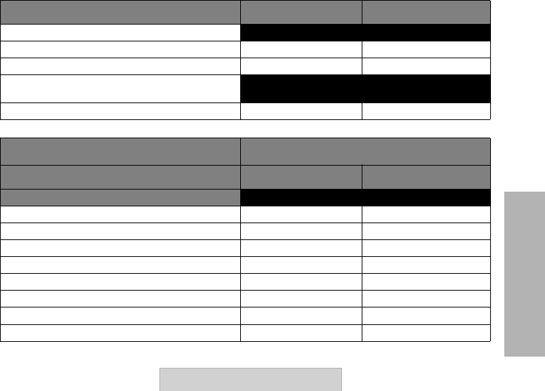
67
APPENDIX A: REPEATER
SPECIFICATIONS
User Guide
Weight
Repeater with Alkaline Frame 2.1 lbs 2.1 lbs
Repeater with Li-On Frame 2.0 lbs 2.0 lbs
Average Battery Life @ 100% duty
(20%/80% operation):
With Alkaline Frame 16 Hours 16 Hours
Other Product Specifications UHF 25 KHz UHF 12.5 KHz
810 Military Standards (1) RPX Repeater 4 W –UHF 450 – 470 MHz
METHOD PROCEDURE
810 - C
Low Pressure 500.4 1
High Temperature 501.4 1, 2
Low Temperature 501.4 1, 2
Temperature Shock 503.4 1
Solar Radiation 505.4 1
Rain 506.4 1
Humidity 507.4 3
Salt Fog 509.4 1
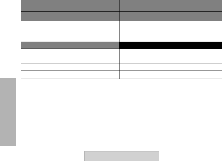
APPENDIX A: REPEATER
SPECIFICATIONS
68 User Guide
Dust 510.4 1
Vibration 514.5 1
Shock 516.5 1
Environmental Specifications
Operating Temperature -30°C to + 60°C (Radio) -30°C to + 60°C (Radio)
Sealing(2) IP55 IP55
Shock & Vibration Polycarbonate Housing passes EIA 603
Dust & Humidity (3) Satisfied EIA 603
(1) MIL STD 810 C, D, E, and F, have blowing rain of sections that call out the device shall survive subjection to 30
minutes of a 4 inch/hour in a 40 mph wind. Dust section calls out blowing dust around 11ug/m3 for 6 hours.
(2) IP55 means the enclosure is dust protected. It also means it is water protected as if jet of water were sprayed
by a hose ( 3 gal/min for at least 3 minutes).
(3) Relative Humidity (RH) is 95% at a -30°C to 60°C.
810 Military Standards (1) RPX Repeater 4 W –UHF 450 – 470 MHz
METHOD PROCEDURE