Motorola Solutions 92FT7118 Mobile 2-Way Radio with WiFi User Manual Installation Manual 1 of 2
Motorola Solutions, Inc. Mobile 2-Way Radio with WiFi Installation Manual 1 of 2
Contents
- 1. Users Guide
- 2. Quick Reference Guide
- 3. Installation Manual 1 of 2
- 4. Installation Manual 2 of 2
- 5. RF Safety Manual
- 6. Manual
Installation Manual 1 of 2

-i
Page
APX™ TWO-WAY RADIOS
APX 8500 MOBILE
RADIO
INSTALLATION MANUAL
Draft

0
Draft

i
Foreword
This manual covers the O2, O3, O5, O7 and O9 models of the ASTRO® APX™ mobile radios. It includes all the information
necessary to install high and mid power radios and configure radio installation inside vehicles.
For details on radio operation or component-level troubleshooting, refer to the applicable manuals available separately. A
list of related publications is provided in the section “Related Publications”
RF Energy Exposure and Product Safety Guide for Mobile Two-way Radios
See “Installation Requirements for Compliance with Radio Frequency (RF) Energy Exposure Safety Standards,”.
Manual Revisions
Changes which occur after this manual is printed are described in PMRs (Publication Manual Revisions). These PMRs
provide complete replacement pages for all added, changed, and deleted items.
To obtain PMRs, go to https://businessonline.motorolasolutions.com.
Parts Ordering
See Appendix A: Replacement Parts Ordering for information on how to obtain replacement parts. For part numbers, refer
to the ASTRO APX Mobile Radio Basic Service Manual (Motorola Solutions publication).
Computer Software Copyrights
The Motorola Solutions products described in this manual may include copyrighted Motorola Solutions computer programs
stored in semiconductor memories or other media. Laws in the United States and other countries preserve for Motorola
Solutions certain exclusive rights for copyrighted computer programs, including, but not limited to, the exclusive right to
copy or reproduce in any form the copyrighted computer program. Accordingly, any copyrighted Motorola Solutions
computer programs contained in the Motorola Solutions products described in this manual may not be copied, reproduced,
modified, reverse-engineered, or distributed in any manner without the express written permission of Motorola Solutions.
Furthermore, the purchase of Motorola Solutions products shall not be deemed to grant either directly or by implication,
estoppel, or otherwise, any license under the copyrights, patents or patent applications of Motorola Solutions, except for the
normal non-exclusive license to use that arises by operation of law in the sale of a product.
Document Copyrights
No duplication or distribution of this document or any portion thereof shall take place without the express written permission
of Motorola Solutions. No part of this manual may be reproduced, distributed, or transmitted in any form or by any means,
electronic or mechanical, for any purpose without the express written permission of Motorola Solutions.
Disclaimer
The information in this document is carefully examined, and is believed to be entirely reliable. However, no responsibility is
assumed for inaccuracies. Furthermore, Motorola Solutions reserves the right to make changes to any products herein to
improve readability, function, or design. Motorola Solutions does not assume any liability arising out of the applications or
use of any product or circuit described herein; nor does it cover any license under its patent rights nor the rights of others.
Trademarks
MOTOROLA, MOTO, MOTOROLA SOLUTIONS and the Stylized M logo are trademarks or registered trademarks of
Motorola Trademark Holdings, LLC and are used under license. All other trademarks are the property of their respective
owners.
© 2018 by Motorola Solutions, Inc.
All rights reserved.
Draft

ii
Installation Requirements for Compliance with
Radio Frequency (RF) Energy Exposure Safety
Standards
ATTENTION!
This radio is intended for use in occupational/controlled conditions, where users have full knowledge
of their exposure and can exercise control over their exposure to meet FCC limits. This radio device is
NOT authorized for general population, consumer, or any other use.
To ensure compliance to RF Energy Exposure Regulations:
• Install only Motorola Solutions approved antennas and accessories
• Be sure that antenna installation is per “Antenna Installation” of this manual
• Be sure that Product Safety and RF Safety Booklet enclosed with this radio is available to the end user
upon completion of the installation of this radio
Before using this product, read the guide enclosed with your radio which contains important operating
instructions for safe usage and RF energy awareness and control for compliance with applicable standards
and regulations.
For a list of Motorola Solutions-approved antennas and other accessories, visit the following web site
which lists approved accessories for your radio model: http://www.motorolasolutions.com.
Draft

Table of Contents iii
MN003109A01
Table of Contents
Foreword..........................................................................................................i
RF Energy Exposure and Product Safety Guide for Mobile Two-way Radios..............................................i
Manual Revisions .........................................................................................................................................i
Parts Ordering ..............................................................................................................................................i
Computer Software Copyrights ....................................................................................................................i
Document Copyrights ...................................................................................................................................i
Disclaimer.....................................................................................................................................................i
Trademarks ..................................................................................................................................................i
Installation Requirements for Compliance with
Radio Frequency (RF) Energy Exposure Safety Standards.......................ii
Mobile Radio Model Numbering Scheme..................................................xiii
Commercial Warranty ..................................................................................xv
Limited Warranty .......................................................................................................................................xv
MOTOROLA SOLUTIONS COMMUNICATION PRODUCTS .........................................................xv
I. What This Warranty Covers And For How Long ....................................................................xv
II. General Provisions ............................................................................................................... xvi
III. State Law Rights ................................................................................................................. xvi
IV. How To Get Warranty Service ............................................................................................ xvi
V. What This Warranty Does Not Cover................................................................................... xvi
VI. Patent And Software Provisions ........................................................................................ xvii
VII. Governing Law.................................................................................................................. xvii
Chapter 1 Introduction ......................................................................... 1-1
1.1 Mobile Radio Description............................................................................................................... 1-1
1.1.1 Dimensions ....................................................................................................................... 1-1
1.2 Standard Configurations ................................................................................................................ 1-6
1.2.1 Dash Mount Configuration ................................................................................................ 1-6
1.2.2 Remote Mount Configuration............................................................................................ 1-8
1.2.3 Multi Control Head .......................................................................................................... 1-11
1.3 Motorcycle Configurations ........................................................................................................... 1-11
1.4 Base/Control Stations .................................................................................................................. 1-11
1.5 Tools Required for APX Mobile Installations ............................................................................... 1-11
Chapter 2 Standard Configurations .................................................... 2-1
2.1 Planning the Installation................................................................................................................. 2-1
2.1.3 Radio Operation Wiring for Dash and Remote Configurations ....................................... 2-12
2.1.3.1 Dash Mount: Power, Ignition, and Emergency Cable Installation.......................... 2-12
2.1.3.2 Remote Mount: Power, Ignition, and Emergency Cable Installation...................... 2-13
2.1.4 Ignition Sense Switch (Radio Wide Advance) ................................................................ 2-15
2.1.5 Motorola Branded SB9600 Siren/PA Configuration/Programming ................................. 2-17
Draft

iv Table of Contents
MN003109A01
2.2 Radio Mounting ........................................................................................................................... 2-18
2.2.2 Remote Mount with Trunnion.......................................................................................... 2-21
2.2.2.1 Remote Mount Control Head Installation............................................................... 2-21
2.2.2.2 Multiple Control Head Installation.......................................................................... 2-24
2.2.2.3 Cable Installation ................................................................................................... 2-26
2.2.2.4 Setting the Initial Control Head ID ......................................................................... 2-26
2.2.2.5 O3 Control Head and Remote Mount Cabling....................................................... 2-27
2.2.3 Locking Kit (Optional) .....................................................................................................2-29
2.2.3.1 All Radios .............................................................................................................. 2-29
2.3 Power Cables (Transceiver and Control Head) ........................................................................... 2-30
2.3.1 O2, O5, O7 or O9 Control Head Power Cables.............................................................. 2-30
2.3.2 Battery Selector Switch................................................................................................... 2-31
2.4 Antenna Installation ..................................................................................................................... 2-32
2.4.1 Selecting an Antenna Site/Location on a Metal Body Vehicle ........................................ 2-32
2.4.2 Multiplexers and Vehicle Installation............................................................................... 2-34
2.4.3 QMA Connection (APX8500 Only) ................................................................................. 2-34
2.4.4 GPS/GLONASS/Wi-Fi/Antenna Placement (APX8500 Only) ......................................... 2-34
2.5 Speaker ....................................................................................................................................... 2-35
2.5.1 Internal Speaker Disassembly ........................................................................................ 2-36
2.6 Microphone Hang-Up Clip ........................................................................................................... 2-38
2.6.1 Standard or O3 Control Head Hang-Up Clip .................................................................. 2-38
2.7 RFID (Option) .............................................................................................................................. 2-38
2.7.1 RFID Reading ................................................................................................................. 2-39
2.7.2 Programming RFID (If Equipped) ................................................................................... 2-41
2.8 Completing the Installation .......................................................................................................... 2-42
Chapter 3 Universal Relay Controller Installation ............................. 3-1
3.1 Universal Relay Controller Mounting ............................................................................................. 3-1
3.2 O7/O9 Universal Relay Controller Cable Assembly ...................................................................... 3-3
3.2.1 Power Cable ..................................................................................................................... 3-3
3.2.2 Ground Cable ................................................................................................................... 3-3
3.2.3 Wires ................................................................................................................................ 3-4
3.2.4 O7/O9 to URC Cable ........................................................................................................ 3-5
Chapter 4 Options and Accessories Installation ............................... 4-1
4.1 Dash-Mount Accessory Installation ............................................................................................... 4-1
4.1.1 Dash-Mount Emergency Pushbutton or Footswitch Installation ....................................... 4-1
4.1.2 Dash-Mount Horn and Lights (External Alarms) Relays ................................................... 4-2
4.2 Remote-Mount Accessory Installation ........................................................................................... 4-2
4.2.1 Emergency Pushbutton or Footswitch Installation............................................................ 4-3
4.2.2 Horn (External Alarm) Relay Installation........................................................................... 4-3
4.2.3 Lights (External Alarm) Relay Installation......................................................................... 4-3
4.2.4 Gunlock Installation .......................................................................................................... 4-3
4.2.5 Horn-Ring Transfer ........................................................................................................... 4-5
4.2.6 Record Audio Out Jack of Transmit and Receive Audio................................................... 4-5
4.2.7 Earphone Jack.................................................................................................................. 4-5
4.2.8 USB Data Cables.............................................................................................................. 4-6
4.2.9 RS232 Cables .................................................................................................................. 4-6
4.3 Vehicle Interface Port Overview .................................................................................................... 4-6
4.3.1 VIP Output Connections ................................................................................................... 4-7
4.3.2 VIP Input Connections ......................................................................................................4-8
Draft

Table of Contents v
MN003109A01
4.4 Accessory Connector Assembly Details (P2) ................................................................................ 4-9
4.4.1 Disassembly and Assembly .............................................................................................. 4-9
4.4.1.1 Disassembly ............................................................................................................ 4-9
4.4.1.2 Assembly ............................................................................................................... 4-10
4.5 Motorola Branded SB9600 Siren Connection to APX 8500......................................................... 4-11
4.6 Compatibility of Emergency when Attaching a Motorola Branded SB9600 Siren........................ 4-13
Chapter 5 Motorcycle Radio Installation ............................................ 5-1
5.1 Motorcycle Radio Description ........................................................................................................ 5-1
5.1.1 Transceiver Enclosure ......................................................................................................5-1
5.1.2 Control/Display Unit .......................................................................................................... 5-1
5.1.3 Control Head Cable .......................................................................................................... 5-1
5.1.4 Microphone ....................................................................................................................... 5-2
5.1.5 External Speaker .............................................................................................................. 5-2
5.1.6 Headset Capability............................................................................................................ 5-2
5.1.7 Antenna ............................................................................................................................ 5-2
5.1.8 Ignition Sense (ACC) Wire................................................................................................ 5-2
5.2 Installation Overview...................................................................................................................... 5-3
5.2.1 General ............................................................................................................................. 5-3
5.2.2 Important Motorcycle Installation Hints ............................................................................. 5-4
5.2.3 Parts Identification ............................................................................................................ 5-5
5.2.4 Order of Installation .......................................................................................................... 5-5
5.3 Installing the Universal Mounting Plate.......................................................................................... 5-6
5.4 Installing the Speaker and Control Head ....................................................................................... 5-7
5.4.1 Handlebar Installation with Speaker and Control Head Mounted Together...................... 5-8
5.4.2 Fuel Tank Console Installation with Speaker and Control Head Mounted Together ........ 5-9
5.4.3 Handlebar Installation with Speaker and Control Head Mounted Separately ................. 5-11
5.4.4 Fuel Tank Console Installation with Speaker and Control Head Mounted Separately ... 5-12
5.5 Installing the Speaker .................................................................................................................. 5-14
5.6 Installing the Microphone Hang-Up Clip ...................................................................................... 5-14
5.6.1 Extension Bracket Mounting ........................................................................................... 5-14
5.6.2 Speaker/Control Head Bracket Side Mounting ............................................................... 5-14
5.6.3 Other Hang-Up Clip Mounting ........................................................................................ 5-15
5.7 Installing Antenna Base, Cables and Multiplexer ........................................................................ 5-15
5.8 Installing the Antenna .................................................................................................................. 5-21
5.9 Cable Routing .............................................................................................................................. 5-21
5.10 Installing the Weather-Resistant Enclosure................................................................................. 5-23
5.11 Transceiver, Cabling and Multiplexer Installation ....................................................................... 5-24
5.11.1 Installing Cabling in the Enclosure.................................................................................. 5-24
5.11.2 Installing the Transceiver................................................................................................5-25
5.12 Installing the Emergency Switch Option ......................................................................................5-27
5.13 Installing the External Alarm Relay Option ..................................................................................5-27
5.14 Installing the Headset Accessory................................................................................................. 5-27
5.15 Installing the O5 Control Head Sunshield....................................................................................5-29
5.16 Horn/Lights Wiring ....................................................................................................................... 5-31
5.17 Emergency Switch Wiring............................................................................................................ 5-31
Chapter 6 Finishing the Installation.................................................... 6-1
6.1 Cable Connection .......................................................................................................................... 6-1
6.1.1 O2 Control Head............................................................................................................... 6-1
6.1.2 O3 Control Head............................................................................................................... 6-1
Draft

vi Table of Contents
MN003109A01
6.1.3 O5 Control Head............................................................................................................... 6-1
6.1.4 O7 Control Head............................................................................................................... 6-2
6.1.5 O9 Control Head............................................................................................................... 6-2
6.2 Dust Cover Installation .................................................................................................................. 6-3
Chapter 7 Best Practices: Installation & Troubleshooting ............... 7-1
7.1 Check Wiring of Ignition and Radio Ignition Sensing..................................................................... 7-1
7.2 Check Physical Installation of Radio Ground and Radio Accessory Wiring .................................. 7-2
7.3 Improve the Electrical Quality of the Power and Ignition Lines ..................................................... 7-2
7.4 Minimize the Effect of Poorly Grounded Antennas........................................................................ 7-3
7.5 Jump-Start the Vehicle .................................................................................................................. 7-3
7.6 Eliminate Noise/Howling from PA Speaker ................................................................................... 7-3
Appendix A Replacement Parts Ordering..............................................A-1
A.1 Basic Ordering Information ............................................................................................................ A-1
A.2 Motorola Online Service and Support............................................................................................ A-1
A.3 Accessories Aftermarket Division (AAD) .......................................................................................A-2
Index .....................................................................................................Index-1
Glossary .........................................................................................Glossary-1
Related Publications
ASTRO APX Mobile Radio O2 Control Head User Guide.......................................................... 68012006035
ASTRO APX Mobile Radio O3 Control Head User Guide .......................................................... 6875946M01
ASTRO APX Mobile Radio O5 Control Head User Guide .......................................................... 6875947M01
ASTRO APX Mobile Radio O7 Control Head User Guide.......................................................... 68012006034
ASTRO APX Mobile Radio O9 Control Head User Guide ......................................................... 68007024014
ASTRO APX Mobile Radio Basic Service Manual .................................................................. MN003076A01
ASTRO APX Mobile Radio O2 Quick Reference Card ................................................................. PMLN6193
ASTRO APX Mobile Radio O3 Quick Reference Card ................................................................. PMLN5591
ASTRO APX Mobile Radio O5 Quick Reference Card ................................................................. PMLN5592
ASTRO APX Mobile Radio O7 Quick Reference Card ................................................................. PMLN6194
ASTRO APX Mobile Radio O9 Quick Reference Card ................................................................. PMLN5711
ASTRO APX Mobile Safety Manual ......................................................................... 6881095C99/NNTN7851
ASTRO APX Wi-Fi Provisioning Leaflet ................................................................ MN001435A01/PMLN7688
Draft

List of Figures vii
MN003109A01
List of Figures
Figure 1-1. Front View of O2 Control Head Attached to APX 8500
Mid Power Dash Mount Transceiver and Trunnion .............................................................. 1-1
Figure 1-2. Side View of O2 Control Head Attached to APX 8500
Mid Power Dash Mount Transceiver and Trunnion ............................................................... 1-1
Figure 1-3. Front View of O3 Control Head with Coiled Cable................................................................ 1-1
Figure 1-4. Side View of O3 Control Head with Coiled Cable ................................................................. 1-1
Figure 1-5. Front View of O5 Control Head Attached to APX 8500
Mid Power Dash Mount Transceiver and Trunnion ............................................................... 1-2
Figure 1-6. Side View of O5 Control Head Attached to APX 8500 Mid Power
Dash Mount Transceiver and Trunnion ................................................................................. 1-2
Figure 1-7. Front View of O7 Control Head Attached to APX 8500 Mid Power Dash Mount Transceiver
and Trunnion ......................................................................................................................... 1-2
Figure 1-8. Side View of O7 Control Head Attached to APX 8500 Mid Power Dash Mount Transceiver and
Trunnion................................................................................................................................ 1-2
Figure 1-9. Front View of Remote Mount and Trunnion .......................................................................... 1-2
Figure 1-10. Side View of Remote Mount and Trunnion ........................................................................... 1-2
Figure 1-11. Front View of O2 Control Head with Remote Mount and Trunnion....................................... 1-3
Figure 1-12. Side View of O2 Control Head with Remote Mount and Trunnion ........................................ 1-3
Figure 1-13. Front View of O5 Control Head with Remote Mount and Trunnion....................................... 1-3
Figure 1-14. Side View of O5 Control Head with Remote Mount and Trunnion ........................................ 1-3
Figure 1-15. Front View of O7 Control Head with Remote Mount and Trunnion....................................... 1-3
Figure 1-16. Side View of O7 Control Head with Remote Mount and Trunnion ........................................ 1-3
Figure 1-17. Front View of O9 Control Head with Trunnion ...................................................................... 1-4
Figure 1-18. Side View of O9 Control Head with Trunnion........................................................................ 1-4
Figure 1-19. Top View of O9 Universal Relay Controller with Trunnion (URC is an orderable accessory) 1-4
Figure 1-20. Side View of O9 UniversalRelay Controller with Trunnion(URC is an orderable accessory) 1-4
Figure 1-21. Siren and Lights Interface Module (SLIM) ............................................................................1-4
Figure 1-22. Front View of SB9600 Whelen Siren .................................................................................... 1-5
Figure 1-23. Siren/PA Cable Connections................................................................................................. 1-5
Figure 1-24. Dash Mount Configuration for O2 Control Head ................................................................... 1-6
Figure 1-25. Dash Mount Configuration for O3 Control Head ................................................................... 1-6
Figure 1-26. Dash Mount Configuration for O5 Control Head ................................................................... 1-7
Figure 1-27. Dash Mount Configuration for O7 Control Head ................................................................... 1-7
Figure 1-28. Remote Mount Configuration with Mid Power Transceiver, Transceiver Interface Board,
CHIB Rear Assembly and O2 Control Head ........................................................................ 1-8
Figure 1-29. Remote Mount Configuration with Mid Power Transceiver, Transceiver Interface Board and
O3 Control Head ................................................................................................................... 1-8
Figure 1-30. Remote Mount Configuration with Mid Power Transceiver, Transceiver Interface Board,
CHIB Rear Assembly and O5 Control Head ......................................................................... 1-9
Figure 1-31. Remote Mount Configuration with Mid Power Transceiver, Transceiver Interface Board, CHIB
Rear Assembly and O7 Control Head................................................................................... 1-9
Figure 1-32. Remote Mount Configuration with Mid Power Transceiver, Transceiver Interface Board and
O9 Control Head ................................................................................................................... 1-9
Figure 1-33. Remote Mount Configuration with Mid Power Radio Transceiver, Universal Relay Controller
and O7 Control Head (URC is optional).............................................................................. 1-10
Figure 1-34. Remote Mount Configuration with Mid Power Radio Transceiver, Universal Relay Controller
and O9 Control Head (URC is optional).............................................................................. 1-10
Figure 2-1. Dash Mount Radios Can Be Located in the Middle Console, on the Transmission Hump, or
Under the Dash..................................................................................................................... 2-2
Draft

viii List of Figures
Figure 2-2. Remote Mount Radio Control Heads Can Be Located in the Middle Console, on the Transmis-
sion Hump, or Under the Dash ............................................................................................. 2-2
Figure 2-3. Remote Mount of the Radio, O9 Control Head and Universal Relay Controller (URC is
optional) ................................................................................................................................ 2-2
Figure 2-4. Radio Installation (O2 Mid Power Dash Mount).................................................................... 2-3
Figure 2-5. Radio Installation (O3 Mid Power Dash Mount).................................................................... 2-3
Figure 2-6. Radio Installation (O5 Mid Power Dash Mount).................................................................... 2-4
Figure 2-7. Radio Installation (O7 Mid Power Dash Mount).................................................................... 2-4
Figure 2-8. Radio Installation (O2 Mid Power Remote Mount) ............................................................... 2-5
Figure 2-9. Radio Installation (O3 Mid Power Remote Mount) ............................................................... 2-6
Figure 2-10. Radio Installation (O5 Mid Power Remote Mount) ............................................................... 2-6
Figure 2-11. Radio Installation (O7 Mid Power Remote Mount) ............................................................... 2-7
Figure 2-12. Radio Installation of O9 Remote Mount with Transceiver (URC is optional) ........................ 2-7
Figure 2-13. Radio Installation (O9 Remote Mount with Pinouts) ............................................................. 2-8
Figure 2-14. Remote Control Head Pinouts .............................................................................................. 2-8
Figure 2-15. Cabling Interconnect Diagram for Dash Mount..................................................................... 2-9
Figure 2-16. Cabling Interconnect Diagram for Remote Mount .............................................................. 2-10
Figure 2-17. Cabling Interconnect Diagram for 09 Remote Mount (URC is optional) ..............................2-11
Figure 2-18. APX8500 Mid Power Trunnion Orientation ......................................................................... 2-18
Figure 2-19. Transmission Hump Trunnion Mounting ............................................................................. 2-20
Figure 2-20. Below Dash Trunnion Mounting.......................................................................................... 2-20
Figure 2-21. O5 Control Head Installation Exploded View (Also applicable for O2 and O7
Control Heads) ........................................................................................................................................ 2-22
Figure 2-22. O9 Control Head Installation Exploded View...................................................................... 2-23
Figure 2-23. O5 and O9 Control Head Rear View .................................................................................. 2-23
Figure 2-24. Multiple Control Heads Parallel Configurations .................................................................. 2-24
Figure 2-25. Multiple Control Heads Series Configurations .................................................................... 2-25
Figure 2-26. APX Mobile O5 Control Head Front View........................................................................... 2-26
Figure 2-27. Radio Display with Current Control Head ID ...................................................................... 2-26
Figure 2-28. APX Mobile O5 Control Head Front View – Mode Knob .................................................... 2-26
Figure 2-29. O3 Control Head................................................................................................................. 2-27
Figure 2-30. O3 Control Head Rear View ............................................................................................... 2-28
Figure 2-31. Hang-Up Clip Installation Exploded View ........................................................................... 2-28
Figure 2-32. Locking Kit (Optional) ........................................................................................................ 2-29
Figure 2-33. HKN6188_ Power Cable with External Speaker Connector ............................................... 2-30
Figure 2-34. HKN6187_ Power Cable with External Speaker Connector, Record
Audio Output Jack (2.5 mm) and Earphone Jack (2.5 mm)................................................ 2-31
Figure 2-35. Battery Selector Switch....................................................................................................... 2-31
Figure 2-36. Multiple Antennas Separation for locations 1-10 ................................................................ 2-33
Figure 2-37. Multiplexer Views................................................................................................................ 2-34
Figure 2-38. GPS/GLONASS and Wi-Fi Antenna Connector on the Back of the Mid Power Radio ....... 2-34
Figure 2-39. Speaker Mounting............................................................................................................... 2-35
Figure 2-40. Removing the screws on the Control Head ........................................................................ 2-36
Figure 2-41. Removing the Control Head ............................................................................................... 2-36
Figure 2-42. Disconnecting the Speaker Connector ............................................................................... 2-37
Figure 2-43. Reattaching the Control Head ............................................................................................ 2-37
Figure 2-44. RFID Location on Mid Power Radio ................................................................................... 2-38
Figure 2-45. Read Angle for Mid Power Radio........................................................................................ 2-39
Figure 2-46. Tag Angle for Mid Power Radio .......................................................................................... 2-39
Figure 2-47. Examples of Reader and Tag Aligned (Reader Orientation)............................................... 2-40
Figure 2-48. Example of Reader and Tag Misaligned (Reader Orientation) ........................................... 2-40
Figure 3-1. Universal Relay Controller Orientation ................................................................................. 3-1
Figure 3-2. Universal Relay Controller Installation Exploded View ......................................................... 3-2
Figure 3-3. Power and Ground Cable Glands......................................................................................... 3-3
Draft

List of Figures ix
MN003109A01
Figure 3-4. Cable Gland Assembly with Gasket...................................................................................... 3-4
Figure 3-5. Wires Installation................................................................................................................... 3-4
Figure 3-6. Wire Installation with Black Stick .......................................................................................... 3-5
Figure 3-7. O7/O9 to URC Cable Installation .......................................................................................... 3-5
Figure 4-1. Emergency Switch Wiring Diagram ......................................................................................4-1
Figure 4-2. Horn/Light Wiring Diagram.................................................................................................... 4-2
Figure 4-3. Radio MAP Connector .......................................................................................................... 4-2
Figure 4-4. Gunlock Switch Redundancy Diagram ................................................................................. 4-4
Figure 4-5. Siren/PA Horn-Ring Connections.......................................................................................... 4-5
Figure 4-6. Remote Control Head Pinouts .............................................................................................. 4-6
Figure 4-7. HKN6196_ VIP Connector Detail.......................................................................................... 4-6
Figure 4-8. Relay Coil.............................................................................................................................. 4-7
Figure 4-9. Exploded View of Accessory Connector Assembly (HLN6863_) ........................................ 4-10
Figure 4-10. J600 Accessory Connector Y-Cable KT000247A01............................................................ 4-11
Figure 4-11. Pinout for cable KT000247A01 ........................................................................................... 4-11
Figure 4-12. Interfacing the Y-cable to the Motorola Branded SB9600 Siren and External Accessories 4-12
Figure 4-13. Field adjustment for Emergency Operation with Siren Accessory ...................................... 4-13
Figure 4-14. Location for Pin 8 ................................................................................................................ 4-13
Figure 5-1. Identification of a Motorcycle Radio by Using a Label .......................................................... 5-1
Figure 5-2. Universal Mounting Plate Installation (Part of Radio Enclosure Kit) ..................................... 5-6
Figure 5-3. Motorcycle Control Head Cabling (3075217A01) ................................................................. 5-7
Figure 5-4. Handlebar Installation with Speaker and Control Head Mounted Together .......................... 5-8
Figure 5-5. Fuel Tank Console Installation with Speaker and Control Head Mounted Together ........... 5-10
Figure 5-6. Handlebar Installation with Speaker and Control Head Mounted Separately ..................... 5-12
Figure 5-7. Fuel Tank Console Installation with Speaker and Control Head Mounted Separately........ 5-13
Figure 5-8. Antenna Band Identification ................................................................................................ 5-15
Figure 5-9. Antenna Port Locations....................................................................................................... 5-16
Figure 5-10. Routing the GPS/Wi-Fi Cable ............................................................................................. 5-17
Figure 5-11. Routing the VHF Antenna Cable......................................................................................... 5-18
Figure 5-12. Routing the 700/800 Antenna Cable...................................................................................5-18
Figure 5-13. Routing the UHF Antenna Cable......................................................................................... 5-19
Figure 5-14. Multiplexer and Trunnion Mounting..................................................................................... 5-19
Figure 5-15. Cable Routing ..................................................................................................................... 5-20
Figure 5-16. Cable from Radio to Multiplexer.......................................................................................... 5-20
Figure 5-17. Cable Routing ..................................................................................................................... 5-21
Figure 5-18. Weather-Resistant Enclosure Installation ........................................................................... 5-23
Figure 5-19. Installing Cables.................................................................................................................. 5-25
Figure 5-20. Installing the Transceiver .................................................................................................... 5-26
Figure 5-21. Motorcycle Wiring Harness Rework....................................................................................5-28
Figure 5-22. Remote Mount Trunnion with Sunshield ............................................................................. 5-29
Figure 5-23. Position the Sunshield ........................................................................................................ 5-29
Figure 5-24. Slide the Control Head onto Trunnion................................................................................. 5-30
Figure 5-25. Position Control Head as Desired....................................................................................... 5-30
Figure 5-26. Horn/Lights Wiring Diagram................................................................................................ 5-31
Figure 5-27. Emergency Switch Wiring Diagram .................................................................................... 5-31
Figure 6-1. Dust Cover Installation Locations ......................................................................................... 6-3
Draft

xList of Tables
MN003109A01_aa
List of Tables
Table 2-1. Dash and Remote O2, O3, O5, O7 or O9 Radio Power ON @ J2 ................................ 2-14
Table 2-2. Remote O2, O5, O7 or O9 Radio Power ON @ J200.................................................... 2-14
Table 2-3. Ignition Interface Cables ................................................................................................ 2-14
Table 2-4. Ignition Sense Switch Settings in CPS........................................................................... 2-15
Table 2-5. Power Level Configurations ........................................................................................... 2-17
Table 2-6. Mid Power Trunnion Kit.................................................................................................. 2-19
Table 2-7. Available CAN Cables.................................................................................................... 2-25
Table 2-8. Power Cables................................................................................................................. 2-30
Table 2-1. Model Number Chart in 12-Digit ASCII Format .............................................................. 2-41
Table 2-2. Serial Number with Radio Band/Tier/Power................................................................... 2-41
Table 4-1. VIP Output Connections................................................................................................... 4-7
Table 4-2. VIP Input Connections ..................................................................................................... 4-8
Table 5-1. Transceiver Installation Parts List .................................................................................. 5-27
Draft

List of Tables xi
MN003109A01_aa
Notes
Draft

xii List of Tables
MN003109A01_aa
Draft

MN003109A01_aa
Mobile Radio Model Numbering Scheme xiii
Mobile Radio Model Numbering Scheme
Position 1 - Type of Unit
M = Mobile
L = Table Top Station
Positions 2 & 3 - Model Series
Position 4 - Frequency Band
Less than 29.7MHz
29.7 to 35.99MHz
36 to 41MHz
42 to 50MHz
300 to 345MHz
66 to 80MHz
74 to 90MHz
Product Specific
VHF Range
136 to 162MHz
146 to 178MHz
174 to 210MHz
190 to 235MHz
330 to 370MHz
366 to 410MHz
403 to 437MHz
438 to 482MHz
470 to 620MHz
Product Specific
806 to 870MHz*
825 to 870MHz
896 to 941MHz
403-470MHz
1.0 to 1.6GHz
1.5 to 2.0GHz
Position 5 - Power Level
0 to 0.7 Watts
0.7 to 0.9 Watts
1.0 to 3.9 Watts
4.0 to 5.0 Watts
5.1 to 6.0 Watts
6.1 to 10 Watts
10.1 to 15 Watts
16 to 25 Watts
26 to 35 Watts
Position 6 - Physical Packages
RF Modem Operation
Receiver Only
Standard Control; No Display
Standard Control; With Display
Limited Keypad; No Display
Limited Keypad; With Display
Full Keypad; No Display
Full Keypad; With Display
Limited Controls; No Display
Limited Controls; Basic Display
Limited Controls; Limited Display
Rotary Controls; Standard Display
Enhanced Controls; Enhanced Display
Low Profile; No Display
Low Profile; Basic Display
Low Profile; Basic Display, Full Keypad
Tranceiver with Selectable Control Head
VDV Control Head
Control Head #2
Position 7 - Channel Spacing
0 =
1 = 5KHz
2 = 6.25KHz
3 = 10KHz
4 = 12.5KHz
5 = 15KHz
6 = 20/25KHz
7 = 30KHz
8 = 12.5/25KHz
9 = Variable/Programmable
Typical Model Number:
Position:
Position 8 - Primary Operation
Conventional/Simplex
Conventional/Duplex
Trunked Twin Type
Dual Mode Trunked
Dual Mode Trunked/Duplex
Trunked Type I
Trunked Type II
FDMA* Digital Dual Mode
TDMA** Digital Dual Mode
Single Sideband
Global Positioning Satellite Capable
Amplitude Companded Sideband (ACSB)
Digital Dispatch
Programmable
Digital Interconnect
Digital Multi-Service
9600 Capable
TDMA
* FDMA = Frequency Division Multiple Access
** TDMA = Time Division Multiple Access
Position 9 - Primary System Type
Conventional
Privacy Plus
Clear SMARTNET
Advanced Conventional Stat-Alert
Enhanced Privacy Plus
Nauganet 888 Series
Japan Specialized Mobile Radio (JSMR)
Multi-Channel Access (MCA)
CoveragePLUS
MPT1327* - Public
MPT1327* - Private
Radiocom
Tone Signalling
Binary Signalling
Phonenet
IDEN Basic
IDEN Advanced Feature
JSMR Digital
LTR Protocol
Single Sideband
Programmable
Secure Conventional
Secure SMARTNET
TETRA
SmartZone
* MPT = Ministry of Posts and Telecommunications
Position 10 - Feature Level
1 = Basic
2 = Limited Package
3 = Limited Plus
4 = Intermediate
5 = Standard Package
6 = Standard Plus
7 = Expanded Package
8 = Expanded Plus
9 = Full Feature/
Programmable
Position 11 - Version
Version Letter (Alpha) - Major Change
Position 12 -
Unique Model Variations
C = Cenelec
N = Standard Package
Positions 13 - 16
SP Model Suffix
1 23 4 5 6 7 8 9 10 11 1213141516
M37 T S S 9 P W 1 A N S P 0 1
30 = APX 7500 24 = APX 2500
25 = APX 6500 22 = APX 4500
36 = APX1500 37 = APX 8500
A
B
C
D
E
F
G
H
J
K
L
M
=
=
=
=
=
=
=
=
=
=
=
=
N
P
Q
R
S
T
U
V
W
X
Y
Z
=
=
=
=
=
=
=
=
=
=
=
=
A
B
C
D
E
F
G
H
J
=
=
=
=
=
=
=
=
=
36 to 60 Watts
61 to 110 Watts
Up to 125 Watts
1 to 25 Watts
25 to 40 Watts
25 to 45 Watts
10 to 35 Watts
10 to 50 Watts
25 to 110 Watts
K
L
M
N
P
Q
R
S
T
=
=
=
=
=
=
=
=
=
A
B
C
D
E
F
G
H
J
K
L
M
N
P
Q
R
S
T
U
V
W
=
=
=
=
=
=
=
=
=
=
=
=
=
=
=
=
=
=
=
=
=
A
B
C
D
E
F
G
H
J
K
L
M
N
P
Q
R
S
T
=
=
=
=
=
=
=
=
=
=
=
=
=
=
=
=
=
=
A
B
C
D
E
F
G
H
J
K
L
M
N
P
Q
R
S
T
U
V
W
X
Y
Z
2
=
=
=
=
=
=
=
=
=
=
=
=
=
=
=
=
=
=
=
=
=
=
=
=
=
* For APX 7500 "K" in Position 4 represents
136-174MHz.
* For APX 7500 "Q" in Position 4 represents
380-470MHz.
* For APX 7500 "S" in Position 4 represent
470-520MHz.
* For APX 7500 "U" in Position 4 represent
762-870MHz.
Note: Values represented are not absolute,
and are given to indicate range only.
Note: Values represented are not absolute,
and are given to indicate range only.
Model Series
UHF Range
Draft

MN003109A01_aa
Notes
xiv Mobile Radio Model Numbering Scheme
Draft

MN003109A01_aa
Commercial Warranty xv
Commercial Warranty
Limited Warranty
MOTOROLA SOLUTIONS COMMUNICATION PRODUCTS
I. What This Warranty Covers And For How Long
MOTOROLA SOLUTIONS INC. (“MOTOROLA”) warrants the MOTOROLA SOLUTIONS
manufactured Communication Products listed below (“Product”) against defects in material and
workmanship under normal use and service for a period of time from the date of purchase as
scheduled below:
Motorola Solutions, at its option, will at no charge either repair the Product (with new or
reconditioned parts), replace it (with a new or reconditioned Product), or refund the purchase price of
the Product during the warranty period provided it is returned in accordance with the terms of this
warranty. Replaced parts or boards are warranted for the balance of the original applicable warranty
period. All replaced parts of Product shall become the property of MOTOROLA SOLUTIONS.
This express limited warranty is extended by MOTOROLA SOLUTIONS to the original end user
purchaser only and is not assignable or transferable to any other party. This is the complete warranty
for the Product manufactured by MOTOROLA SOLUTIONS. MOTOROLA SOLUTIONS assumes no
obligations or liability for additions or modifications to this warranty unless made in writing and
signed by an officer of MOTOROLA SOLUTIONS. Unless made in a separate agreement between
MOTOROLA SOLUTIONS and the original end user purchaser, MOTOROLA SOLUTIONS does not
warrant the installation, maintenance or service of the Product.
MOTOROLA SOLUTIONS cannot be responsible in any way for any ancillary equipment not
furnished by MOTOROLA SOLUTIONS which is attached to or used in connection with the Product,
or for operation of the Product with any ancillary equipment, and all such equipment is expressly
excluded from this warranty. Because each system which may use the Product is unique,
MOTOROLA SOLUTIONS disclaims liability for range, coverage, or operation of the system as a
whole under this warranty.
ASTRO APX Mobile Radio One (1) Year
Product Accessories One (1) Year
Draft

MN003109A01_aa
xvi Commercial Warranty
II. General Provisions
This warranty sets forth the full extent of MOTOROLA SOLUTIONS'S responsibilities regarding the
Product. Repair, replacement or refund of the purchase price, at MOTOROLA SOLUTIONS's option,
is the exclusive remedy. THIS WARRANTY IS GIVEN IN LIEU OF ALL OTHER EXPRESS
WARRANTIES. IMPLIED WARRANTIES, INCLUDING WITHOUT LIMITATION, IMPLIED
WARRANTIES OF MERCHANTABILITY AND FITNESS FOR A PARTICULAR PURPOSE, ARE
LIMITED TO THE DURATION OF THIS LIMITED WARRANTY. IN NO EVENT SHALL MOTOROLA
SOLUTIONS BE LIABLE FOR DAMAGES IN EXCESS OF THE PURCHASE PRICE OF THE
PRODUCT, FOR ANY LOSS OF USE, LOSS OF TIME, INCONVENIENCE, COMMERCIAL LOSS,
LOST PROFITS OR SAVINGS OR OTHER INCIDENTAL, SPECIAL OR CONSEQUENTIAL
DAMAGES ARISING OUT OF THE USE OR INABILITY TO USE SUCH PRODUCT, TO THE FULL
EXTENT SUCH MAY BE DISCLAIMED BY LAW.
III. State Law Rights
SOME STATES DO NOT ALLOW THE EXCLUSION OR LIMITATION OF INCIDENTAL OR
CONSEQUENTIAL DAMAGES OR LIMITATION ON HOW LONG AN IMPLIED WARRANTY
LASTS, SO THE ABOVE LIMITATION OR EXCLUSIONS MAY NOT APPLY.
This warranty gives specific legal rights, and there may be other rights which may vary from state to
state.
IV. How To Get Warranty Service
You must provide proof of purchase (bearing the date of purchase and Product item serial number)
in order to receive warranty service and, also, deliver or send the Product item, transportation and
insurance prepaid, to an authorized warranty service location. Warranty service will be provided by
Motorola Solutions through one of its authorized warranty service locations. If you first contact the
company which sold you the Product, it can facilitate your obtaining warranty service. You can also
call Motorola Solutions at 1-888-567-7347 US/Canada.
V. What This Warranty Does Not Cover
A. Defects or damage resulting from use of the Product in other than its normal and customary
manner.
B. Defects or damage from misuse, accident, water, or neglect.
C. Defects or damage from improper testing, operation, maintenance, installation, alteration,
modification, or adjustment.
D. Breakage or damage to antennas unless caused directly by defects in material workmanship.
E. A Product subjected to unauthorized Product modifications, disassemblies or repairs
(including, without limitation, the addition to the Product of non-Motorola Solutions supplied
equipment) which adversely affect performance of the Product or interfere with Motorola
Solutions's normal warranty inspection and testing of the Product to verify any warranty
claim.
F. Product which has had the serial number removed or made illegible.
G. Rechargeable batteries if:
- any of the seals on the battery enclosure of cells are broken or show evidence of
tampering.
- the damage or defect is caused by charging or using the battery in equipment or service
other than the Product for which it is specified.
H. Freight costs to the repair depot.
Draft

MN003109A01_aa
Commercial Warranty xvii
I. A Product which, due to illegal or unauthorized alteration of the software/firmware in the
Product, does not function in accordance with MOTOROLA SOLUTIONS’s published
specifications or the FCC certification labeling in effect for the Product at the time the Product
was initially distributed from MOTOROLA SOLUTIONS.
J. Scratches or other cosmetic damage to Product surfaces that does not affect the operation of
the Product.
K. Normal and customary wear and tear.
VI. Patent And Software Provisions
MOTOROLA SOLUTIONS will defend, at its own expense, any suit brought against the end user
purchaser to the extent that it is based on a claim that the Product or parts infringe a United States
patent, and MOTOROLA SOLUTIONS will pay those costs and damages finally awarded against the
end user purchaser in any such suit which are attributable to any such claim, but such defense and
payments are conditioned on the following:
A. that MOTOROLA SOLUTIONS will be notified promptly in writing by such purchaser of any
notice of such claim;
B. that MOTOROLA SOLUTIONS will have sole control of the defense of such suit and all
negotiations for its settlement or compromise; and
C. should the Product or parts become, or in MOTOROLA SOLUTIONS's opinion be likely to
become, the subject of a claim of infringement of a United States patent, that such purchaser
will permit MOTOROLA SOLUTIONS, at its option and expense, either to procure for such
purchaser the right to continue using the Product or parts or to replace or modify the same so
that it becomes noninfringing or to grant such purchaser a credit for the Product or parts as
depreciated and accept its return. The depreciation will be an equal amount per year over the
lifetime of the Product or parts as established by MOTOROLA SOLUTIONS.
MOTOROLA SOLUTIONS will have no liability with respect to any claim of patent infringement which
is based upon the combination of the Product or parts furnished hereunder with software, apparatus
or devices not furnished by MOTOROLA SOLUTIONS, nor will MOTOROLA SOLUTIONS have any
liability for the use of ancillary equipment or software not furnished by MOTOROLA SOLUTIONS
which is attached to or used in connection with the Product. The foregoing states the entire liability of
MOTOROLA SOLUTIONS with respect to infringement of patents by the Product or any parts
thereof.
Laws in the United States and other countries preserve for MOTOROLA SOLUTIONS certain
exclusive rights for copyrighted MOTOROLA SOLUTIONS software such as the exclusive rights to
reproduce in copies and distribute copies of such Motorola Solutions software. MOTOROLA
SOLUTIONS software may be used in only the Product in which the software was originally
embodied and such software in such Product may not be replaced, copied, distributed, modified in
any way, or used to produce any derivative thereof. No other use including, without limitation,
alteration, modification, reproduction, distribution, or reverse engineering of such MOTOROLA
SOLUTIONS software or exercise of rights in such MOTOROLA SOLUTIONS software is permitted.
No license is granted by implication, estoppel or otherwise under MOTOROLA SOLUTIONS patent
rights or copyrights.
VII. Governing Law
This Warranty is governed by the laws of the State of Illinois, USA.
Draft

MN003109A01_aa
Notes
xviii Commercial Warranty
Draft
Chapter 1 Introduction
This manual covers the installation procedures for ASTRO APX mobile and motorcycle radios with
O2, O3, O5, O7 and O9 control heads, and accessories required to complete the radio system. The
radio system consists of a control head, radio, antenna, microphone, speaker, cabling, Universal
Relay Controller (URC), and accessories.
NOTE: APX Mobile high power do not support motorcycle radios.
1.1 Mobile Radio Description
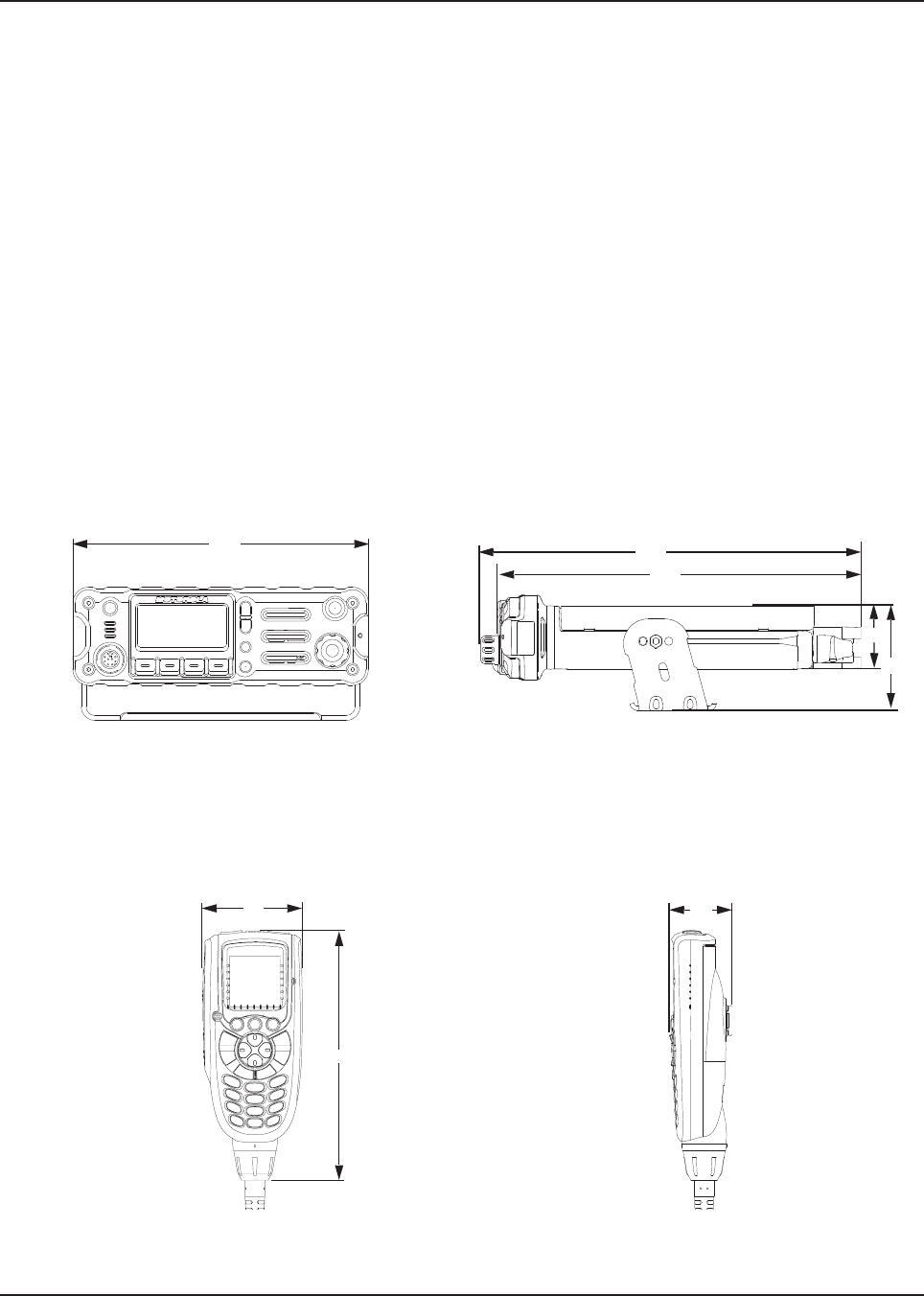
1.1.1 Dimensions
When installing the radio, plan the installation carefully and leave additional room in the rear of the
radio for cabling and accessory connections. Allow additional room in the front of the radio for
access, controls, and cabling for remote mount and to the sides of the radio so that you can access
and install the trunnion screws/wing screws.
NOTE: The measurement unit used in Figure 1-1 to Figure 1-20 is millimeter.
Figure 1-1. Front View of O2 Control Head Attached
to APX 8500
Mid Power Dash Mount Transceiver and Trunnion
Figure 1-2. Side View of O2 Control Head
Attached to APX 8500
Mid Power Dash Mount Transceiver and Trunnion
206
306
51
84
293
61
153
38
Draft
MN003109A01_aa
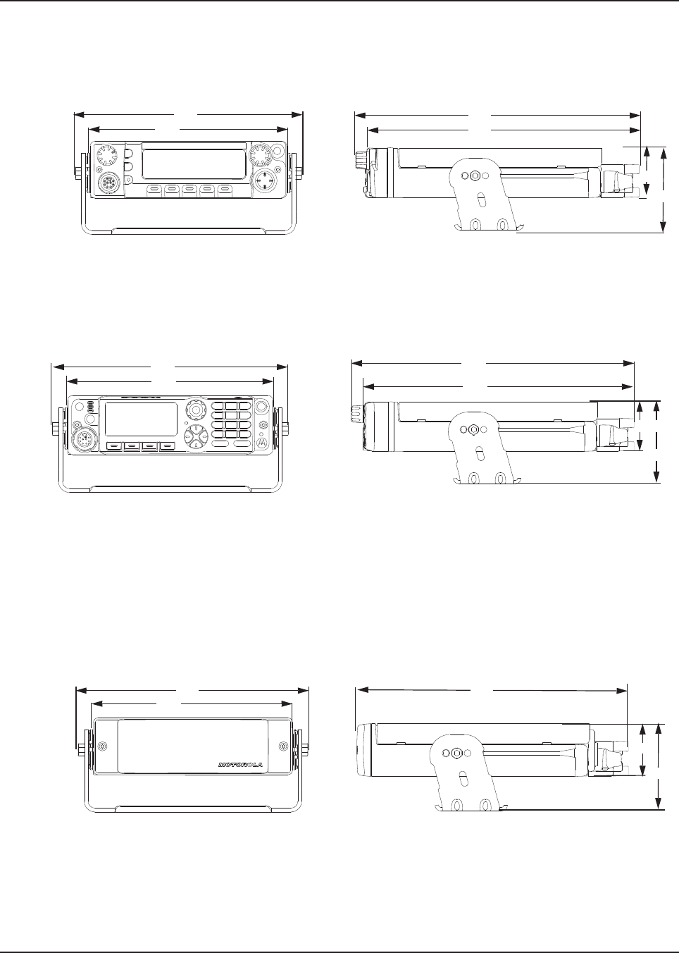
1-2 Introduction Mobile Radio Description
Figure 1-9 and Figure 1-10, show the basic dimensions of the remote mount transceiver trunnion
APX mobile radio.
Figure 1-3. Front View of O3 Control
Head with Coiled Cable
Figure 1-4. Side View of O3 Control
Head with Coiled Cable
Figure 1-5. Front View of O5 Control Head
Attached to APX 8500
Mid Power Dash Mount Transceiver and Trunnion
Figure 1-6. Side View of O5 Control Head
Attached to APX 8500 Mid Power
Dash Mount Transceiver and Trunnion
Figure 1-7. Front View of O7 Control Head
Attached to APX 8500 Mid Power Dash Mount
Transceiver and Trunnion
Figure 1-8. Side View of O7 Control Head Attached
to APX 8500 Mid Power Dash Mount Transceiver
and Trunnion
Figure 1-9. Front View of Remote Mount and
Trunnion
Figure 1-10. Side View of Remote Mount and
Trunnion
178
206 286
274
51
84
206
178
291
278
84
51
206
178
261
51
84
Draft
MN003109A01_aa
Introduction Mobile Radio Description 1-3
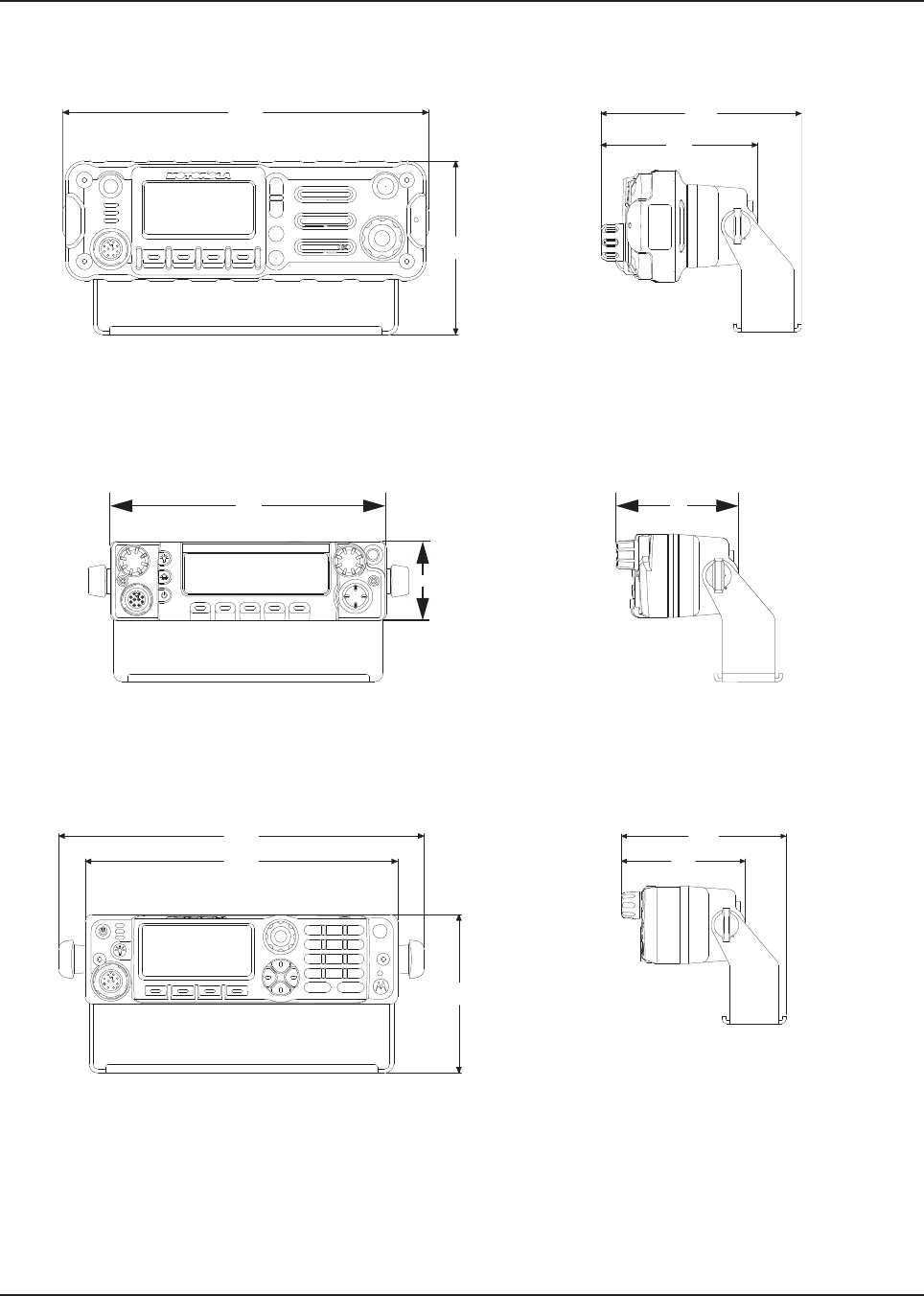
Figure 1-11. Front View of O2 Control Head with
Remote Mount and Trunnion
Figure 1-12. Side View of O2 Control Head with
Remote Mount and Trunnion
Figure 1-13. Front View of O5 Control Head with
Remote Mount and Trunnion
Figure 1-14. Side View of O5 Control Head with
Remote Mount and Trunnion
Figure 1-15. Front View of O7 Control Head with
Remote Mount and Trunnion
Figure 1-16. Side View of O7 Control Head with
Remote Mount and Trunnion
209
99
123
97
51
180
75
209
178
91
108
82
Draft
MN003109A01_aa
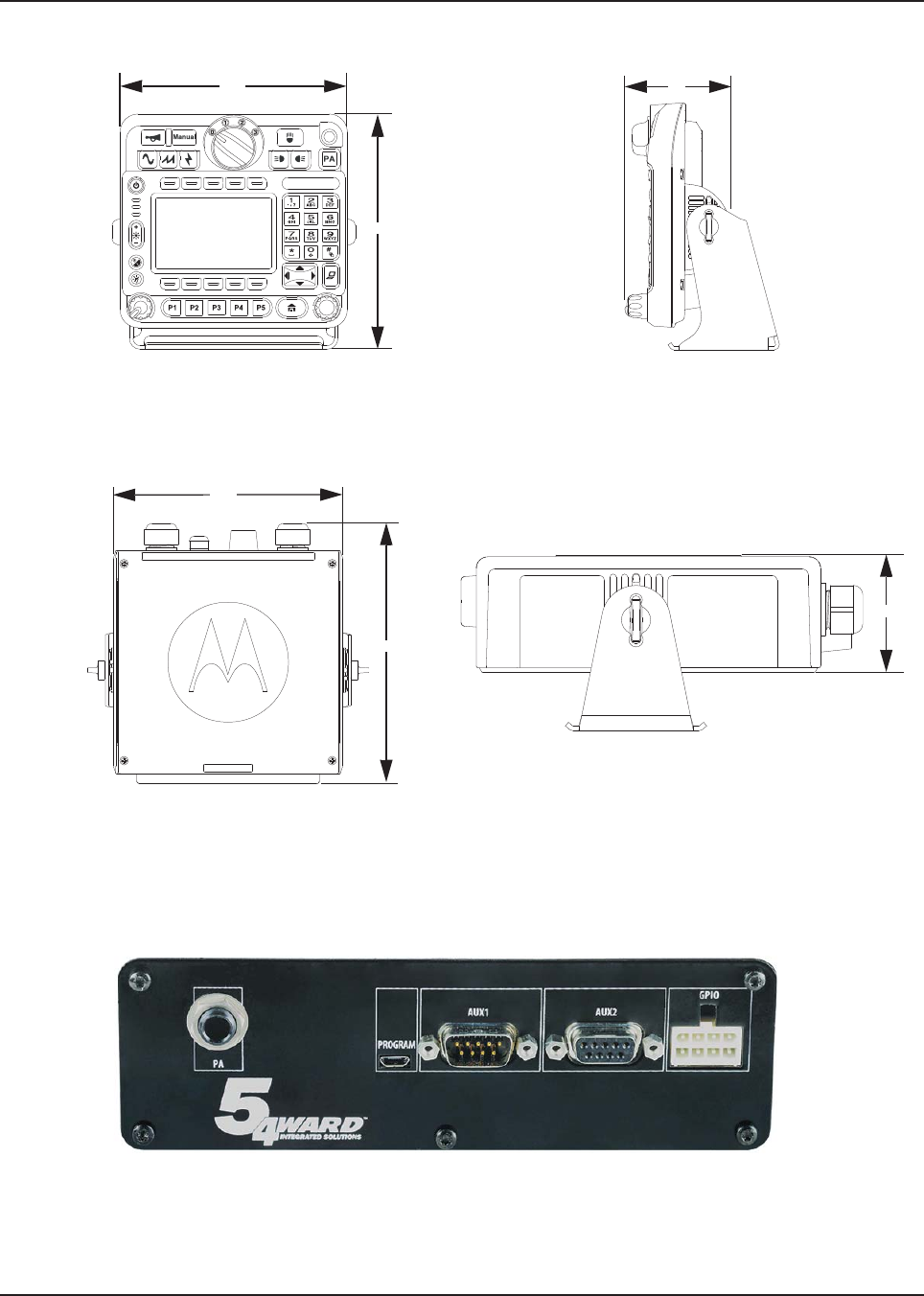
1-4 Introduction Mobile Radio Description
Figure 1-21. Siren and Lights Interface Module (SLIM)
Figure 1-17. Front View of O9 Control Head with
Trunnion
Figure 1-18. Side View of O9 Control Head with
Trunnion
Figure 1-19. Top View of O9 Universal Relay
Controller with Trunnion (URC is an
orderable accessory)
Figure 1-20. Side View of O9 Universal Relay
Controller with Trunnion (URC is an orderable
accessory)
178
190 83
185
210
61.5
Draft
MN003109A01_aa
Introduction Mobile Radio Description 1-5
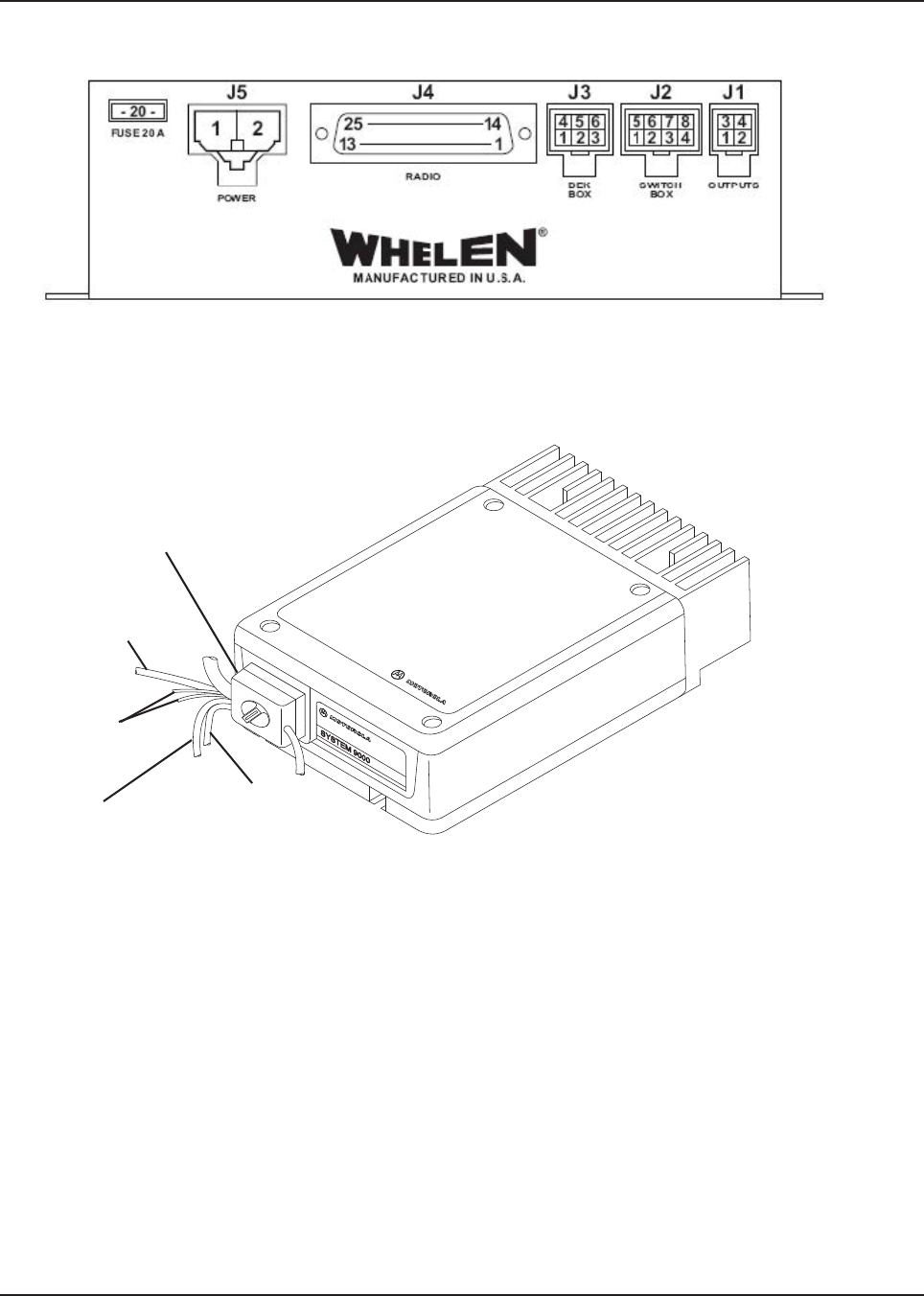
Figure 1-22. Front View of SB9600 Whelen Siren
Figure 1-23. Siren/PA Cable Connections
Siren/PA Unit
T-Cable for Dual Control
Head Only
To Switch Box or
DEK
Speaker
Leads
Red Fused Cable
Connects to Battery
Positive Terminal
Black Chassis
Ground Cable
Draft
MN003109A01_aa
1-6 Introduction Standard Configurations
1.2 Standard Configurations
1.2.1 Dash Mount Configuration - Mid Power
NOTE: The dash mount configuration is not applicable for O9 control heads.
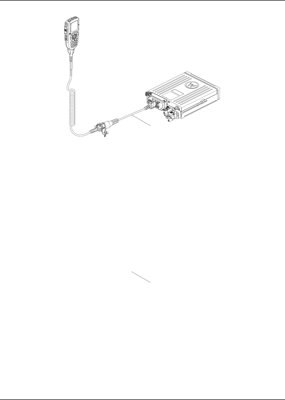
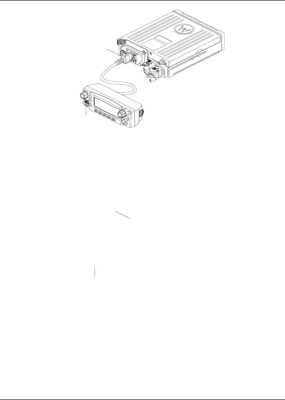
There are two versions of the APX mobile dash mount. The first are the O2, O5 and O7 control
heads which are mounted on the front of the transceiver housing. The second is the O3 control head
which is connected to the transceiver through a coiled cable, which is plugged into the CAN
connector on the transceiver.
Electrical connection between the two takes place within the radio through a flexible circuit board
between the connectors on the front of the transceiver and at the back of the control head for O2, O5
and O7.
Figure 1-24. Dash Mount Configuration for O2 Control Head
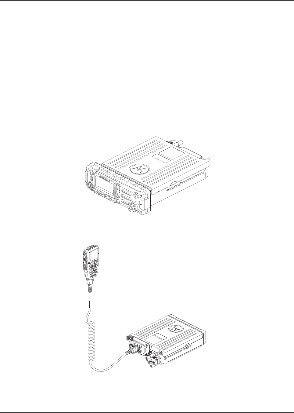
Figure 1-25. Dash Mount Configuration for O3 Control Head
(No Extension Cable Present)
Draft
MN003109A01_aa
Introduction Standard Configurations 1-7
For details on this configuration, see See 2.2.1.
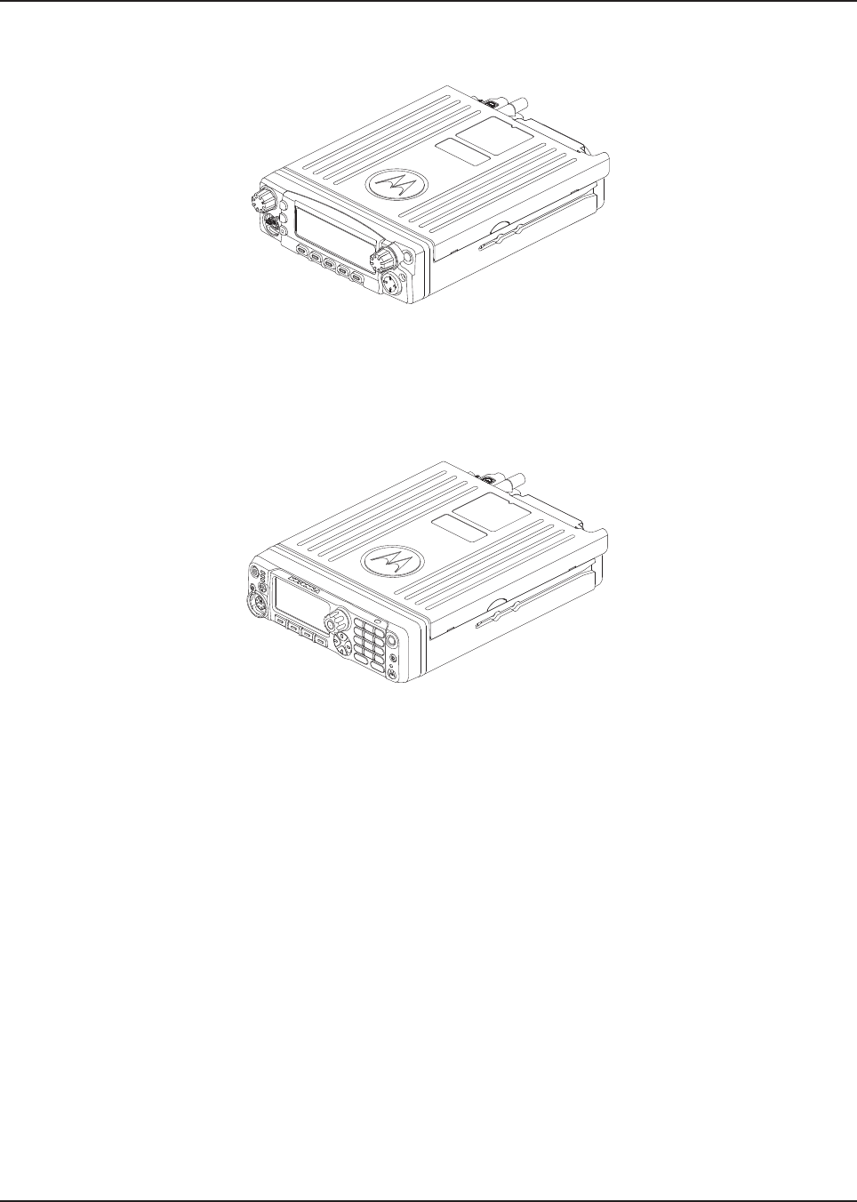
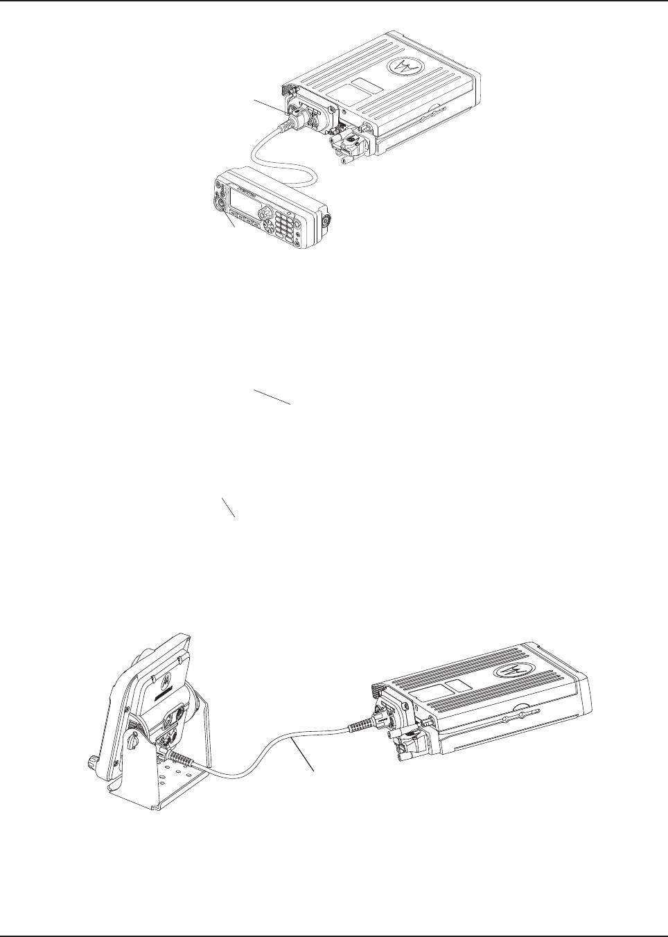
Figure 1-26. Dash Mount Configuration for O5 Control Head
Figure 1-27. Dash Mount Configuration for O7 Control Head
Draft
MN003109A01_aa
1-8 Introduction Standard Configurations
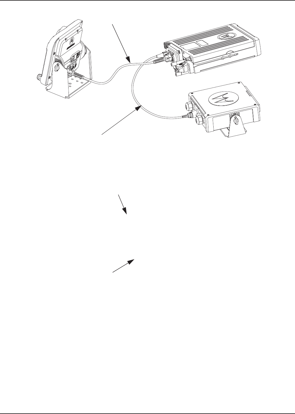
1.2.2 Remote Mount Configuration
In the remote mount configuration, the transceiver and the control head are mounted separately in
the vehicle. The O2, O5, O7 and O9 control heads are mounted in remote trunnions near the
operator. The transceiver and control head are mounted using a trunnion or other mounting
hardware. If the transceiver is located in a car trunk, ensure that it is mounted securely and that
sufficient cooling is provided. Do not cover the transceiver with baggage, blankets, and others.
NOTE: The keypad mic should only be plugged into the Mobile Microphone Port (MMP) connector
located on the control head, in either dash mount or remote mount configuration.
Figure 1-28. Remote Mount Configuration with Mid Power Transceiver, Transceiver Interface Board,
CHIB Rear Assembly and O2 Control Head
Figure 1-29. Remote Mount Configuration with High Power Transceiver, Transceiver Interface Board,
CHIB Rear Assembly and O2 Control Head
MMP
MMP
MMP
MMP
Draft
MN003109A01_aa
Introduction Standard Configurations 1-9
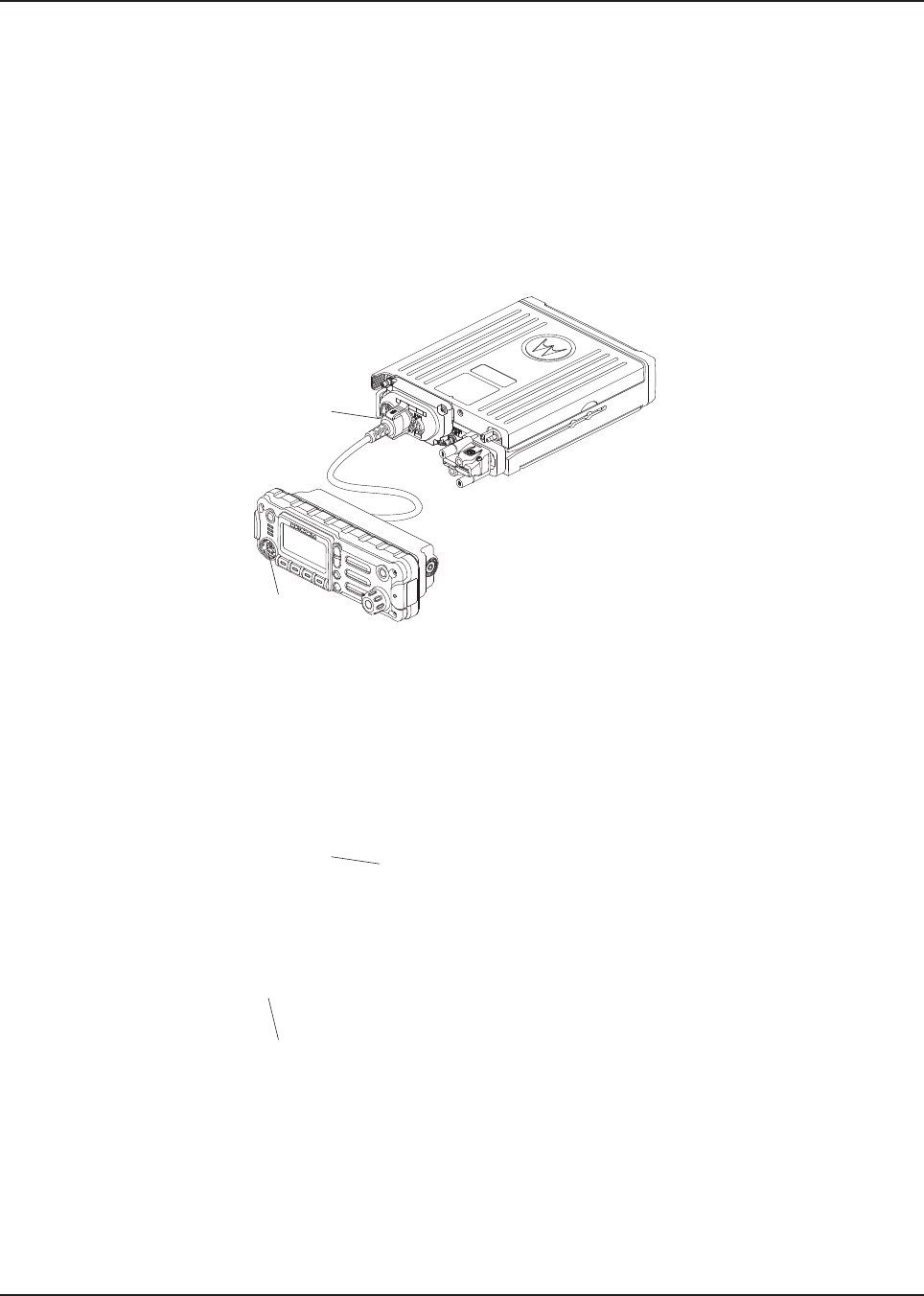
Figure 1-30. Remote Mount Configuration with Mid Power Transceiver,
Transceiver Interface Board and O3 Control Head
Figure 1-31. Remote Mount Configuration with High Power Transceiver,
Transceiver Interface Board and O3 Control Head
5 m (17 ft) Extension Cable
5 m (17 ft) Extension Cable
Draft
MN003109A01_aa
1-10 Introduction Standard Configurations
Figure 1-32. Remote Mount Configuration with Mid Power Transceiver, Transceiver Interface Board,
CHIB Rear Assembly and O5 Control Head
Figure 1-33. Remote Mount Configuration with High Power Transceiver, Transceiver Interface Board,
CHIB Rear Assembly and O5 Control Head
MMP
MMP
MMP
MMP
Draft
MN003109A01_aa
Introduction Standard Configurations 1-11
Figure 1-34. Remote Mount Configuration with Mid Power Transceiver,
Transceiver Interface Board, CHIB Rear Assembly and O7 Control Head
Figure 1-35. Remote Mount Configuration with High Power Transceiver,
Transceiver Interface Board, CHIB Rear Assembly and O7 Control Head
Figure 1-36. Remote Mount Configuration with Mid Power Transceiver,
Transceiver Interface Board and O9 Control Head
MMP
MMP
MMP
MMP
17 ft Extension Cable
Draft
MN003109A01_aa
1-12 Introduction Standard Configurations
Figure 1-37. Remote Mount Configuration with High Power Transceiver,
Transceiver Interface Board and O9 Control Head
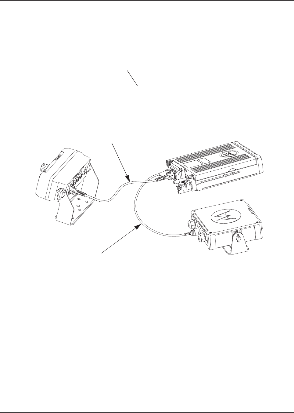
Figure 1-38. Remote Mount Configuration with Mid Power Radio Transceiver,
Universal Relay Controller and O7 Control Head (URC is optional)
(Also Applicable for O2 and O5 Control Heads)
17 ft Extension Cable
17 ft Extension Cable
O7 to URC Cable
Draft

MN003109A01_aa
Introduction Standard Configurations 1-13
Figure 1-39. Remote Mount Configuration with High Power Radio Transceiver,
Universal Relay Controller and O7 Control Head (URC is optional)
(Also Applicable for O2 and O5 Control Heads)
17 ft Extension Cable
O7 to URC Cable
Draft
MN003109A01_aa
1-14 Introduction Standard Configurations
Figure 1-40. Remote Mount Configuration with Mid Power Radio Transceiver,
Universal Relay Controller and O9 Control Head (URC is optional)
Figure 1-41. Remote Mount Configuration with High Power Radio Transceiver,
Universal Relay Controller and O9 Control Head (URC is optional)
For details on these configurations, See 2.2.2.
17 ft Extension Cable
O9 to URC Cable
O9 to URC Cable
17 ft Extension Cable
Draft

MN003109A01_aa
Introduction Motorcycle Configurations - Mid Power 1-15
1.2.3 Multi Control Head
The multi control head option allows separate, remotely operated control heads to operate and
control the radio. For example, a fire truck could have a control head located in the cab and on the
rear of the truck so that the radio could be operated from outside the vehicle.
1.3 Motorcycle Configurations - Mid Power
NOTE: The motorcycle configurations are not applicable for O9 control heads.
See Chapter 5: Motorcycle Radio Installation for further information.
1.4 Base/Control Stations
NOTE: The base/control station option is not applicable for O9 control heads.
If mobile radio equipment is installed at a fixed location and operated as a control station or as a
fixed unit, the antenna installation must comply with the following requirements in order to ensure
optimal performance and compliance with the RF energy exposure limits in the standards and
guidelines listed in the Safety Manual (refer to related publications):
• The antenna should be mounted outside the building on the roof or a tower if at all possible.
• As with all fixed site antenna installations, it is the responsibility of the licensee to manage the
site in accordance with applicable regulatory requirements and may require additional
compliance actions such as site survey measurements, signage, and site access restrictions in
order to ensure that exposure limits are not exceeded.
1.5 Tools Required for APX Mobile Installations
Tool Part Number
10 mm wrench –
5 mm Allen wrench –
Regular slot screwdriver of Phillips #2 –
Pin removal tool 6680163F01
Draft

MN003109A01_aa
1-16 Introduction Tools Required for APX Mobile Installations
Draft

Chapter 2 Standard Configurations
2.1 Planning the Installation
The APX mobile radio operates only in negative ground electrical systems with a valid operating
range of 13.6 V +/- 20%. Before starting the radio installation, make sure that the ground polarity of
the vehicle is correct. Accidentally reversing the polarity could damage the radio and cause the cable
fuses to blow.
Planning is the key to fast, easy radio installation. Before starting the installation, inspect the vehicle
and determine how and where you intend to mount the antenna, radio, and accessories. Plan wire
and cable runs to provide maximum protection from pinching, crushing, and overheating.
Before installing any electrical equipment, check the vehicle manufacturer user
manual for warnings or recommendations.
The installation of this device should be completed by an authorized servicer or
installer. Failure to properly install the device may result in damage to the device, or
improper operation.
!
C a u t i o n
Draft
MN003109A01_aa
2-2 Standard Configurations Planning the Installation
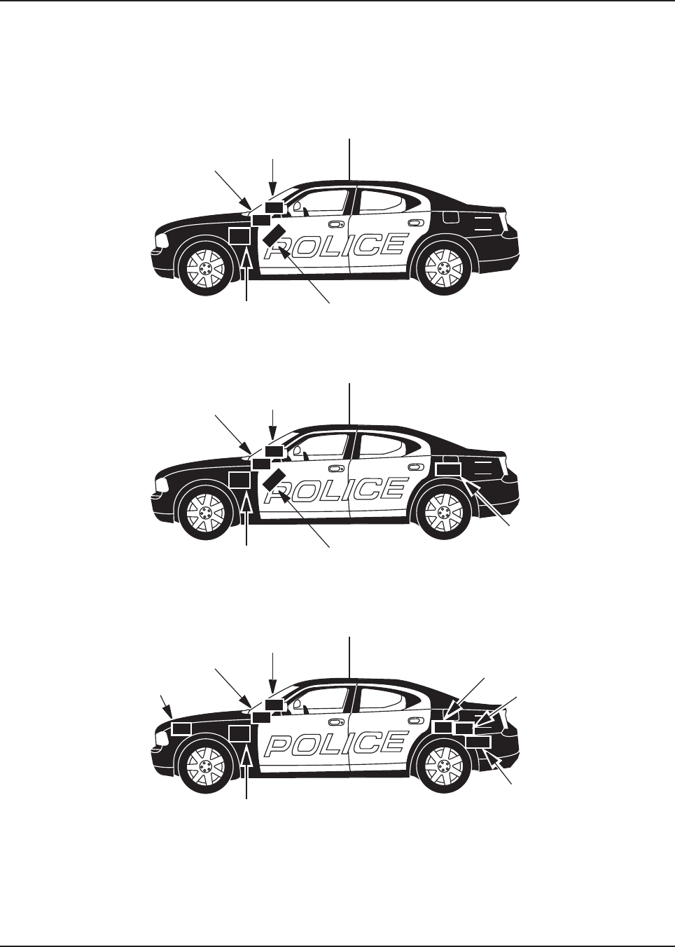
2.1.1 Installation Examples
The mobile two-way radio offers various methods of installation, with accessories placed to the
vehicle as desired. The radio can be a dash or remote mount except with O9 control head, which can
only be mounted remotely. The O9 control head with the radio and the URC can only be mounted
remotely (see Figure 2-3).
Figure 2-1. Dash Mount Radios Can Be Located in the Middle Console, on the
Transmission Hump, or Under the Dash (Mid Power)
Figure 2-2. Remote Mount Radio Control Heads Can Be Located in the Middle
Console, on the Transmission Hump, or Under the Dash (Mid Power)
Figure 2-3. Remote Mount of the Radio, O9 Control Head
and Universal Relay Controller (URC is optional)
911
Antenna
Radio
Speaker
Battery Radio
911
Antenna
Control
Head
Speaker
Battery Control
Head
Radio
911
Antenna
Control Head
Speaker
Battery
Universal Relay
Controller Box
Radio
Siren Speaker Siren Box
Draft
MN003109A01_aa
Standard Configurations Planning the Installation 2-3
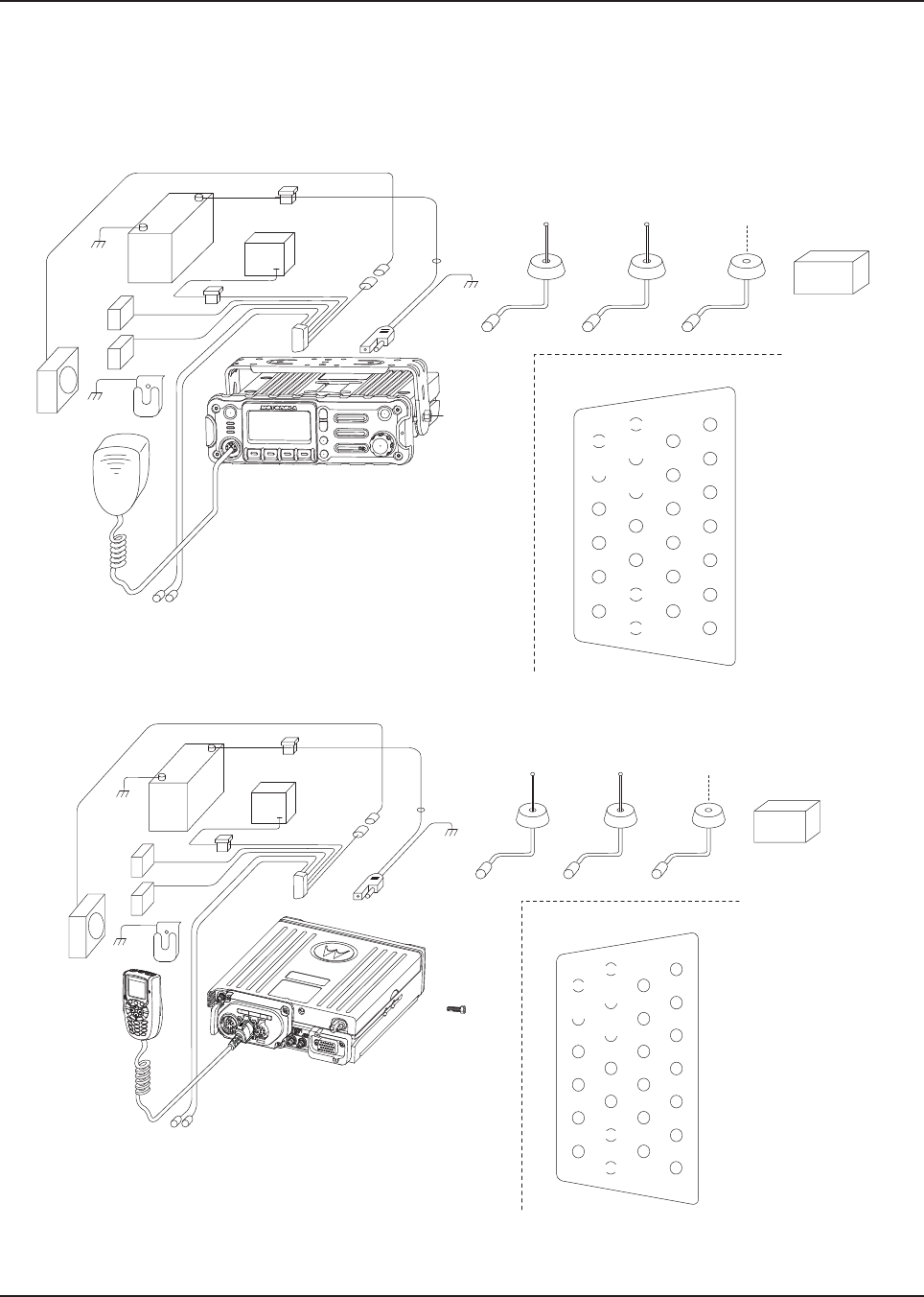
2.1.2 Wiring Diagrams
Figure 2-4 through Figure 2-18 show the wiring diagrams for all the possible configurations. The title
under each figure identifies the O2, O3, O5, O7 or O9 control head configurations. Identify which of
these figures shows the configuration that you are installing, and use the diagram when planning the
installation.
Figure 2-4. Radio Installation (O2 Mid Power Dash Mount)
Figure 2-5. Radio Installation (O3 Mid Power Dash Mount)
BATTERY
HORN
RELAY
LIGHT
RELAY
MIC
CLIP
SPEAKER
MIC
EMERGENCY
SWITCH
FUSE
FUSE
BLOCK
(+)
(-)
RED LEAD
FUSE
FIREWALL
HOLE
MOUNTING
SCREW
DASH MOUNT RADIO
ANTENNA
CONNECTION
ANTENNA 1
IGN SENSE (ACC)
P2
(SEE J2
PINOUT)
DC
POWER
CABLE
TRUNNION J2
REAR ACCESSORY CONNECTOR
1
7
8
14
13
20
21
26
SPKR-
SPKR+
VIPOUT 2
12V
(RELAY)
VIPOUT 1
12V
(RELAY)
GROUND
EMERGENCY
IGN SENSE
(ACC)
ANTENNA
CONNECTION
ANTENNA 2
WIFI (OPTIONAL)
ANTENNA
CONNECTION
ANTENNA 3
GPS (OPTIONAL)
Multi-
plexer
BATTERY
HORN
RELAY
LIGHT
RELAY
MIC
CLIP
SPEAKER
MIC
EMERGENCY
SWITCH
FUSE
FUSE
BLOCK
(+)
(-)
RED LEAD
FUSE
FIREWALL
HOLE
MOUNTING
SCREW
RADIO
ANTENNA
CONNECTION
ANTENNA 1
IGN SENSE (ACC)
P2
(SEE J2
PINOUT)
DC
POWER
CABLE
TRUNNION
J2
REAR ACCESSORY CONNECTOR
1
7
8
14
13
20
21
26
SPKR-
SPKR+
VIPOUT 2
12V
(RELAY)
VIPOUT 1
12V
(RELAY)
GROUND
EMERGENCY
IGN SENSE
(ACC)
ANTENNA
CONNECTION
ANTENNA 2
WIFI (OPTIONAL)
ANTENNA
CONNECTION
ANTENNA 3
GPS (OPTIONAL)
Multi-
plexer
Draft
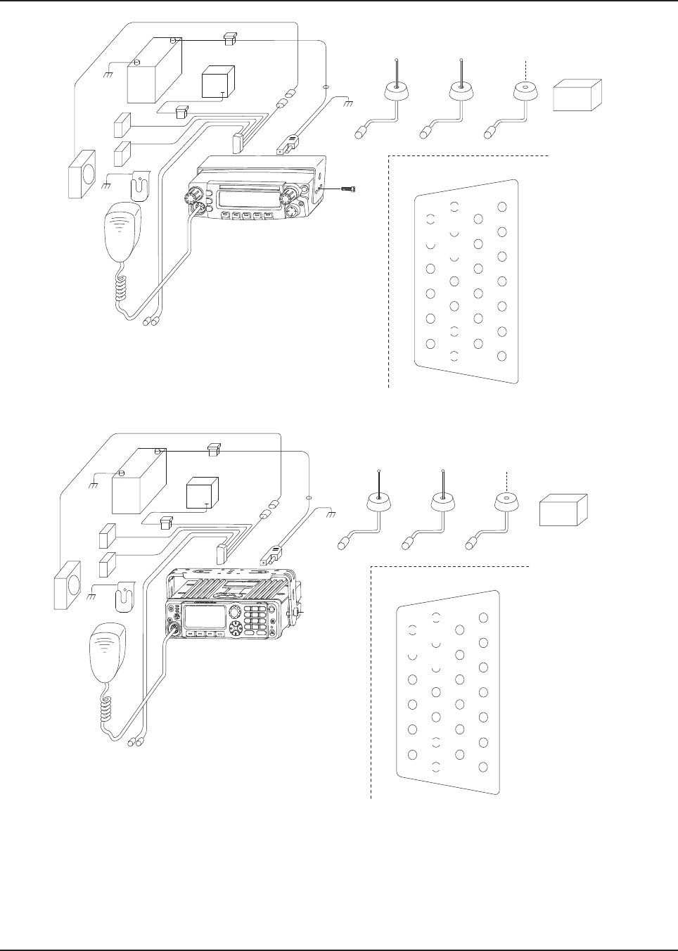
MN003109A01_aa
2-4 Standard Configurations Planning the Installation
Figure 2-6. Radio Installation (O5 Mid Power Dash Mount)
Figure 2-7. Radio Installation (O7 Mid Power Dash Mount)
BATTERY
HORN
RELAY
LIGHT
RELAY
MIC
CLIP
SPEAKER
MIC
EMERGENCY
SWITCH
FUSE
FUSE
BLOCK
(+)
(-)
RED LEAD
FUSE
FIREWALL
HOLE
MOUNTING
SCREW
DASH MOUNT RADIO
ANTENNA
CONNECTION
ANTENNA 1
IGN SENSE (ACC)
P2
(SEE J2
PINOUT)
DC
POWER
CABLE
TRUNNION J2
REAR ACCESSORY CONNECTOR
1
7
8
14
13
20
21
26
SPKR-
SPKR+
VIPOUT 2
12V
(RELAY)
VIPOUT 1
12V
(RELAY)
GROUND
EMERGENCY
IGN SENSE
(ACC)
ANTENNA
CONNECTION
ANTENNA 2
WIFI (OPTIONAL)
ANTENNA
CONNECTION
ANTENNA 3
GPS (OPTIONAL)
Multi-
plexer
BATTERY
HORN
RELAY
LIGHT
RELAY
MIC
CLIP
SPEAKER
MIC
EMERGENCY
SWITCH
FUSE
FUSE
BLOCK
(+)
(-)
RED LEAD
FUSE
FIREWALL
HOLE
MOUNTING
SCREW
DASH MOUNT RADIO
ANTENNA
CONNECTION
ANTENNA 1
IGN SENSE (ACC)
P2
(SEE J2
PINOUT)
DC
POWER
CABLE
TRUNNION J2
REAR ACCESSORY CONNECTOR
1
7
8
14
13
20
21
26
SPKR-
SPKR+
VIPOUT 2
12V
(RELAY)
VIPOUT 1
12V
(RELAY)
GROUND
EMERGENCY
IGN SENSE
(ACC)
ANTENNA
CONNECTION
ANTENNA 2
WIFI (OPTIONAL)
ANTENNA
CONNECTION
ANTENNA 3
GPS (OPTIONAL)
Multi-
plexer
Draft
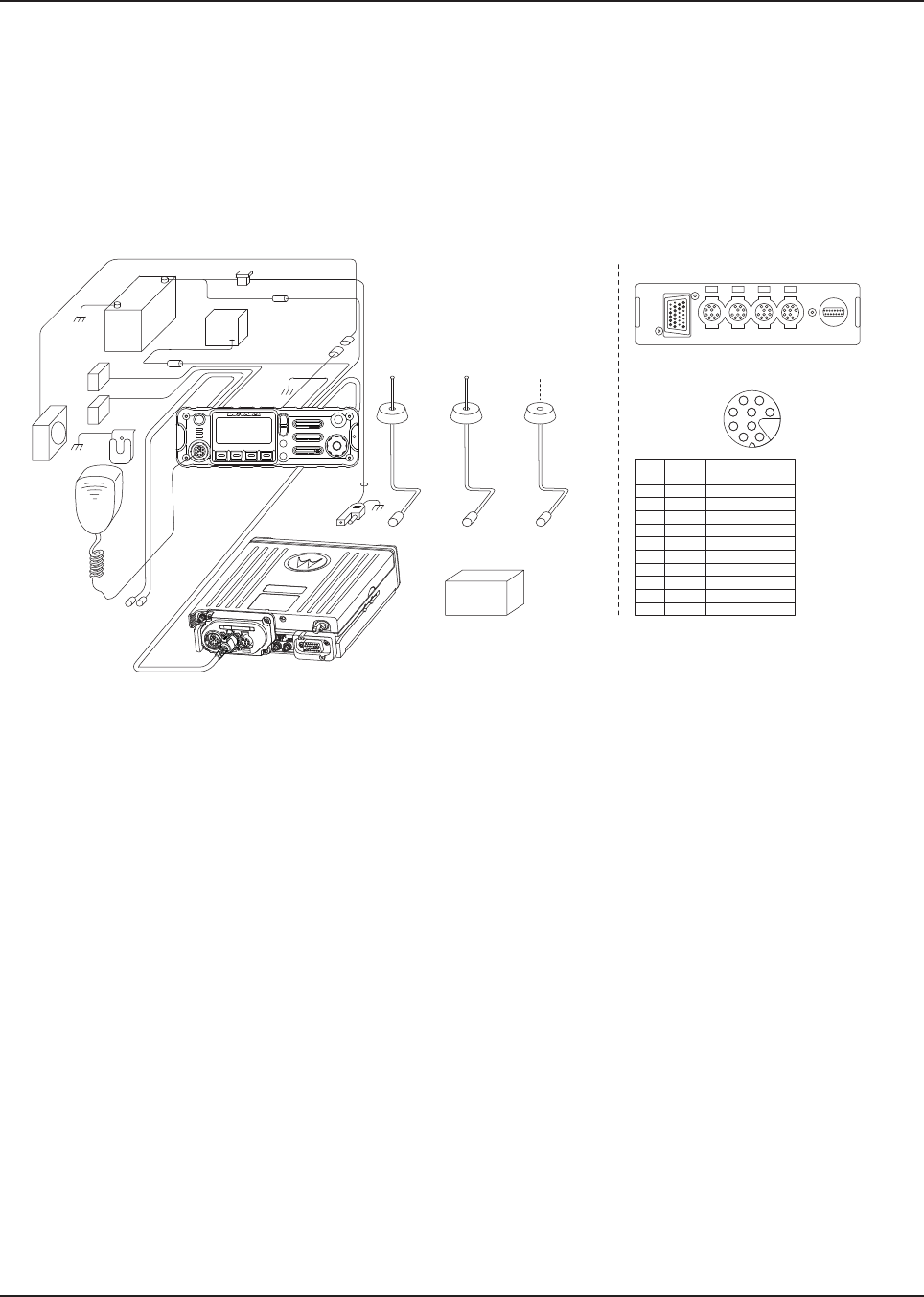
MN003109A01_aa
Standard Configurations Planning the Installation 2-5
NOTE: In dash mount configuration, it is mandatory that a rear accessory cable be attached at the
back of a mid power transceiver, in order to ground the Emergency pin to GND. Or, an
emergency footswitch or pushbutton switch must be attached at the back of a mid power.
If the emergency pin is not grounded, upon the attachment of the A+ cable at the DC
connector, the radio detects a HIGH for the emergency pin state, and assume that emergency
has been activated. This attempts to power on the radio, and results in excessive current draw
and incorrect radio operation. Refer to Section 2.1.3.1 for further details and recommended
wiring of emergency in dash mount.
Figure 2-8. Radio Installation (O2 Mid Power Remote Mount)
Figure 2-9. Radio Installation (O2 High Power Remote Mount)
PWR
SPK
J400-1 RED SWB +
J400-2 GREEN GND
J400-3 - NO PIN
J400-4 - "VIP" detect: GPIO=HIGH
J400-5 BLUE VIP_OUT_1
J400-6 YELLOW VIP_OUT_2
J400-7 BLACK VIP_OUT_3
J400-8 WHITE VIP_IN_1 (VIP_IN GPIO)
J400-9 ORANGE VIP_IN_2 (VIP_IN GPIO)
J400-10 VIOLET VIP_IN_3
CAN CAN DEK
VIP
J400
ACC USB
PORTS ON REAR OF REMOTE CONTROL HEAD
VIP CONNECTOR PIN-OUT
J400
6
9
10
7
4
2
5
8
1
Radio
Pin
Number
VIP Cable
(HKN6196_)
Wire Color
Function
BATTERY
HORN
RELAY
LIGHT
RELAY
MIC
CLIP
SPEAKER
MIC
EMERGENCY
SWITCH
RED LEAD
FUSE
BLOCK
YELLOW
LEAD
BLACK
LEAD
(+)
(-)
FUSE
FUSE
CONTROL HEAD FIREWALL
HOLE
ANTENNA
CONNECTION
ANTENNA 1
DC POWER
CABLE
RADIO
FUSE
ANTENNA
CONNECTION
ANTENNA 2
WIFI (OPTIONAL)
ANTENNA
CONNECTION
ANTENNA 3
GPS (OPTIONAL)
Multi-
plexer
Multi-
plexer
Draft
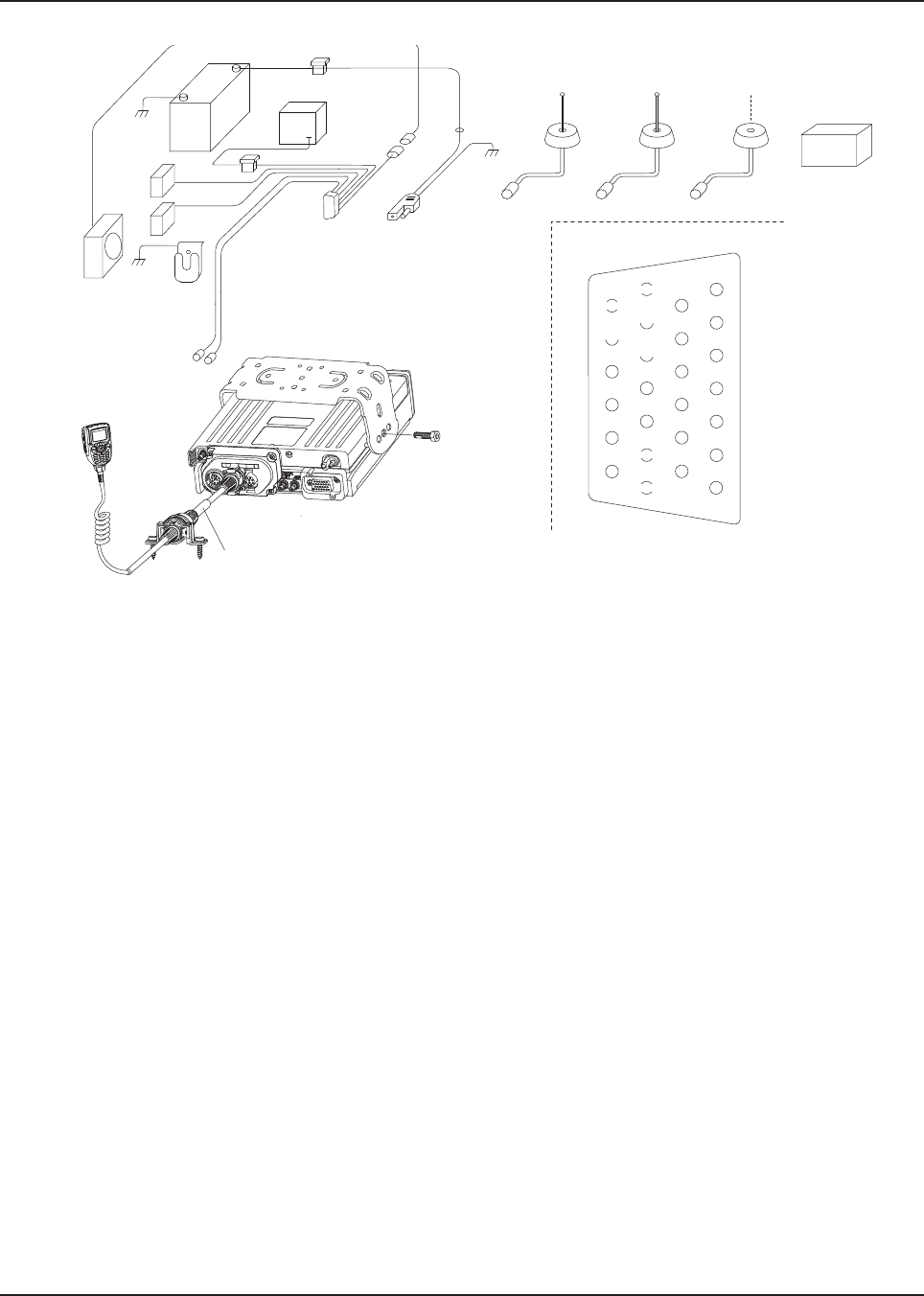
MN003109A01_aa
2-6 Standard Configurations Planning the Installation
Figure 2-10. Radio Installation (O3 Mid Power Remote Mount)
Figure 2-11. Radio Installation (O3 High Power Remote Mount)
BATTERY
HORN
RELAY
LIGHT
RELAY
CH
hang
up
box
SPEAKER
O3
5m (17ft)
CABLE (PMLN4958)
EMERGENCY
SWITCH
FUSE
FUSE
BLOCK
(+)
(-)
RED LEAD
FUSE
FIREWALL
HOLE
MOUNTING
SCREW
IGN SENSE (ACC)
P2
(SEE J626
PINOUT)
CABLE
HLN 6863
DC
POWER
CABLE
TRUNNION
ANTENNA
CONNECTION
ANTENNA 1
J2
REAR ACCESSORY CONNECTOR
1
7
8
14
13
20
21
26
SPKR-
SPKR+
VIPOUT 2
12V
(RELAY)
VIPOUT 1
12V
(RELAY)
GROUND
EMERGENCY
IGN SENSE
(ACC)
ANTENNA
CONNECTION
ANTENNA 2
WIFI (OPTIONAL)
ANTENNA
CONNECTION
ANTENNA 3
GPS (OPTIONAL)
Multi-
plexer
Multi-
plexer
Draft
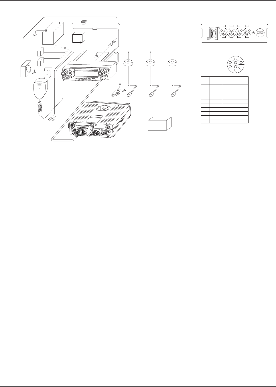
MN003109A01_aa
Standard Configurations Planning the Installation 2-7
Figure 2-12. Radio Installation (O5 Mid Power Remote Mount)
Figure 2-13. Radio Installation (O5 High Power Remote Mount)
BATTERY
HORN
RELAY
LIGHT
RELAY
MIC
CLIP
SPEAKER
MIC
EMERGENCY
SWITCH
RED LEAD
FUSE
BLOCK
YELLOW
LEAD
BLACK
LEAD
(+)
(-)
FUSE
FUSE
CONTROL HEAD FIREWALL
HOLE
ANTENNA
CONNECTION
ANTENNA 1
DC POWER
CABLE
RADIO
FUSE
ANTENNA
CONNECTION
ANTENNA 2
WIFI (OPTIONAL)
ANTENNA
CONNECTION
ANTENNA 3
GPS (OPTIONAL)
PWR
SPK
J400-1 RED SWB +
J400-2 GREEN GND
J400-3 - NO PIN
J400-4 - "VIP" detect: GPIO=HIGH
J400-5 BLUE VIP_OUT_1
J400-6 YELLOW VIP_OUT_2
J400-7 BLACK VIP_OUT_3
J400-8 WHITE VIP_IN_1 (VIP_IN GPIO)
J400-9 ORANGE VIP_IN_2 (VIP_IN GPIO)
J400-10 VIOLET VIP_IN_3
CAN CAN DEK
VIP
J400
ACC USB
PORTS ON REAR OF REMOTE CONTROL HEAD
VIP CONNECTOR PIN-OUT
J400
6
9
10
7
4
2
5
8
1
Radio
Pin
Number
VIP Cable
(HKN6196_)
Wire Color
Function
Multi-
plexer
Multi-
plexer
Draft
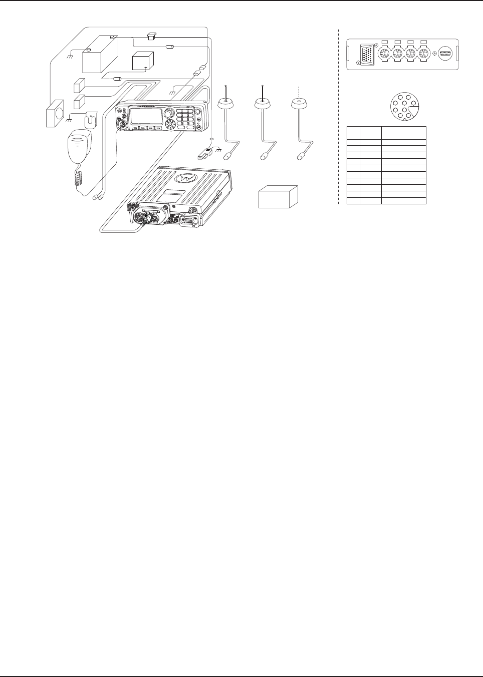
MN003109A01_aa
2-8 Standard Configurations Planning the Installation
Figure 2-14. Radio Installation (O7 Mid Power Remote Mount)
Figure 2-15. Radio Installation (O7 High Power Remote Mount)
Refer to Section 2.1.3.2 and Section 4.2.1 for further details and recommended wiring of emergency
in remote mount.
PWR
SPK
J400-1 RED SWB +
J400-2 GREEN GND
J400-3 - NO PIN
J400-4 - "VIP" detect: GPIO=HIGH
J400-5 BLUE VIP_OUT_1
J400-6 YELLOW VIP_OUT_2
J400-7 BLACK VIP_OUT_3
J400-8 WHITE VIP_IN_1 (VIP_IN GPIO)
J400-9 ORANGE VIP_IN_2 (VIP_IN GPIO)
J400-10 VIOLET VIP_IN_3
CAN CAN DEK
VIP
J400
ACC USB
PORTS ON REAR OF REMOTE CONTROL HEAD
VIP CONNECTOR PIN-OUT
J400
6
9
10
7
4
2
5
8
1
Radio
Pin
Number
VIP Cable
(HKN6196_)
Wire Color
Function
BATTERY
HORN
RELAY
LIGHT
RELAY
MIC
CLIP
SPEAKER
MIC
EMERGENCY
SWITCH
RED LEAD
FUSE
BLOCK
YELLOW
LEAD
BLACK
LEAD
(+)
(-)
FUSE
FUSE
CONTROL HEAD FIREWALL
HOLE
ANTENNA
CONNECTION
ANTENNA 1
DC POWER
CABLE
RADIO
FUSE
ANTENNA
CONNECTION
ANTENNA 2
WIFI (OPTIONAL)
ANTENNA
CONNECTION
ANTENNA 3
GPS (OPTIONAL)
Multi-
plexer
Multi-
plexer
Draft
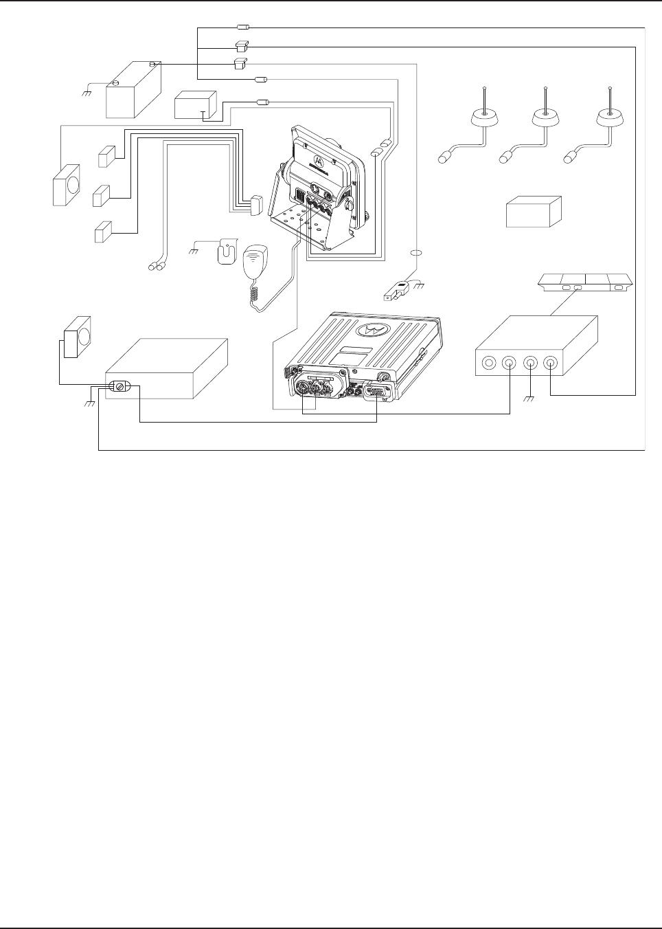
MN003109A01_aa
Standard Configurations Planning the Installation 2-9
Figure 2-16. Radio Installation of O9 Remote Mount with Transceiver (URC is optional) - Mid Power
MIC
MIC
CLIP
EMERGENCY
SWITCH
(SEE J2
PINOUT)
GUN LOCK
EARJACK
Control Head
Speaker
Siren Bullhorn
Siren Box
RED LEAD
HORN
RELAY
ANTENNA 1
ANTENNA
CONNECTION
FIREWALL
HOLE
DC POWER
CABLE
URC Controller Box
BLACK
LEAD
LIGHTBAR
O9 TO URC Cable
RADIO
CAN Cable
ANTENNA
CONNECTION
WIFI (OPTIONAL)
ANTENNA
CONNECTION
GPS (OPTIONAL)
(+)
(-)
RED LEAD
RED LEAD
RED LEAD
YELLOW LEAD
CONTROL HEAD
FUSE
FUSE
FUSE
FUSE
BLOCK
BATTERY
FUSE
CIRCUIT BREAKER
Multi-
plexer
Draft

MN003109A01_aa
2-10 Standard Configurations Planning the Installation
Figure 2-17. Radio Installation of O9 Remote Mount with Transceiver (URC is optional) - High Power
Multi-
plexer
Draft
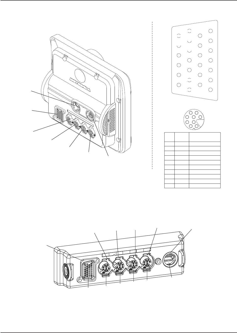
MN003109A01_aa
Standard Configurations Planning the Installation 2-11
Figure 2-18. Radio Installation (O9 Remote Mount with Pinouts)
Refer to Section 2.1.3.2 and Section 4.2.1 for further details and recommended wiring of emergency
in remote mount.
Figure 2-19. Remote Control Head Pinouts
VIP CONNECTOR PIN-OUT
J400
6
9
10
7
4
2
5
8
1
J400-1 RED SWB +
J400-2 GREEN GND
J400-3 - NO PIN
J400-4 - "VIP" detect: GPIO=HIGH
J400-5 BLUE VIP_OUT_1
J400-6 YELLOW VIP_OUT_2
J400-7 BLACK VIP_OUT_3
J400-8 WHITE VIP_IN_1 (VIP_IN GPIO)
J400-9 ORANGE VIP_IN_2 (VIP_IN GPIO)
J400-10 VIOLET VIP_IN_3
Radio
Pin
Number
VIP Cable
(HKN6196_)
Wire Color
Function
J2
REAR ACCESSORY CONNECTOR
1
7
8
14
13
20
21
26
SPKR-
SPKR+
VIPOUT 2
12V
(RELAY)
VIPOUT 1
12V
(RELAY)
GROUND
EMERGENCY
IGN SENSE
(ACC)
MMP
J400
DEK/VIP
(YELLOW)
J300R
CAN
(BLUE)
J500
USB
J100
M.A.P.
J200
PWR/SPKR
(RED) J300L
CAN
(BLUE)
M.A.P. PWR
SPK
(RED)
CAN
(BLUE)
CAN
(BLUE)
DEK
VIP
(YELLOW)
USB
J100
J200 J300L J300R J400 J500
Draft
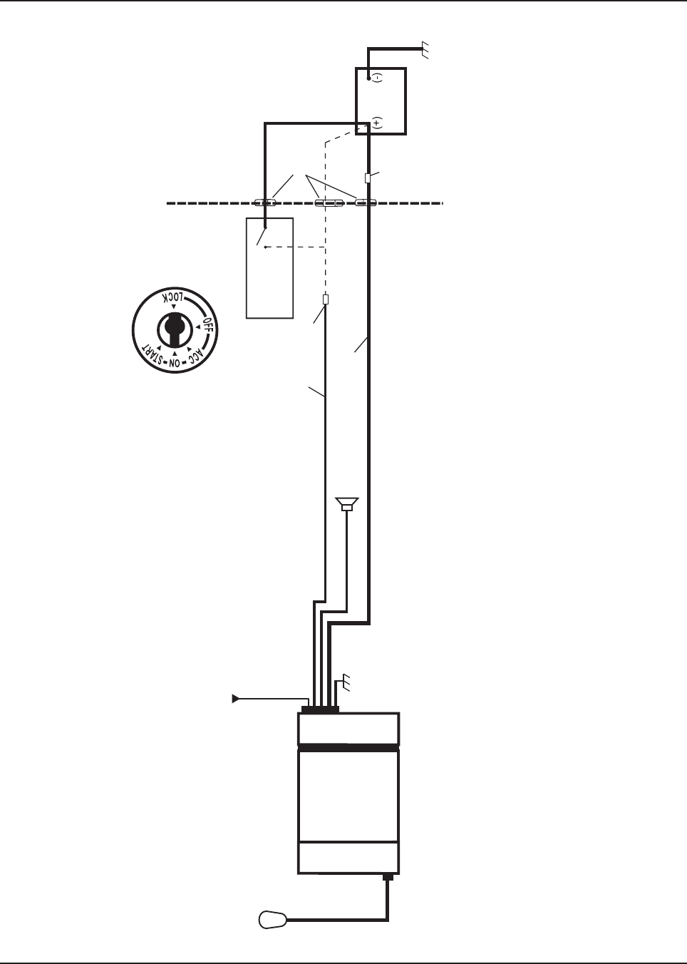
MN003109A01_aa
2-12 Standard Configurations Planning the Installation
RADIO COMPARTMENT = OPERATOR COMPARTMENT VEHICLE BATTERY
COMPARTMENT
TIB
CONTROL HEAD
ACC line
MICROPHONE
TRANSCEIVER
SPEAKER A+ (RED)
DASH IGN SENSE
(thin RED) FUSE
FUSE
SEE NOTE
VEHICLE
IGNITION SWITCH
GROMMET
VEHICLE
BATTERY
CHASSIS GND
NOTE:
See TABLE 2-1 for wiring of the thin RED wire on rear accessory plug. A good GROUND connection to the car chassis is required for correct radio operation.
NOTE:
Ignition sense cable uses either 3-amp fuse (6580283E01) or 4-amp fuse (6580283E02)
Figure 2-20. Cabling Interconnect Diagram for Dash Mount
Draft
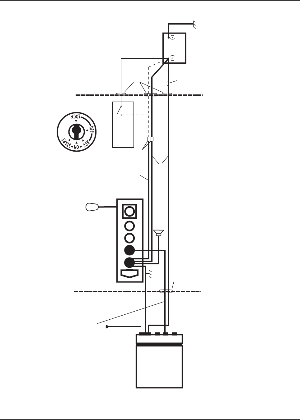
MN003109A01_aa
Standard Configurations Planning the Installation 2-13
IGN SENSE
(YELLOW)
ACC line
VEHICLE
IGNITION SWITCH
GROMMET
VEHICLE
BATTERY
CHASSIS GND
MICROPHONE
CONTROL HEAD (REAR VIEW)
DIGITAL CONTROL CABLE
REMOTE MOUNT OPERATION
RADIO COMPARTMENT VEHICLE BATTERY
COMPARTMENT
OPERATOR COMPARTMENT
TRANSCEIVER
TIB
GROMMET
SPEAKER A+ (RED)
SEE NOTE
FUSE
FUSE
NOTE:
See TABLE 2-1 for wiring of the YELLOW wire. A good GROUND connection to the car chassis is required for correct radio operation.
Figure 2-21. Cabling Interconnect Diagram for Remote Mount
Draft
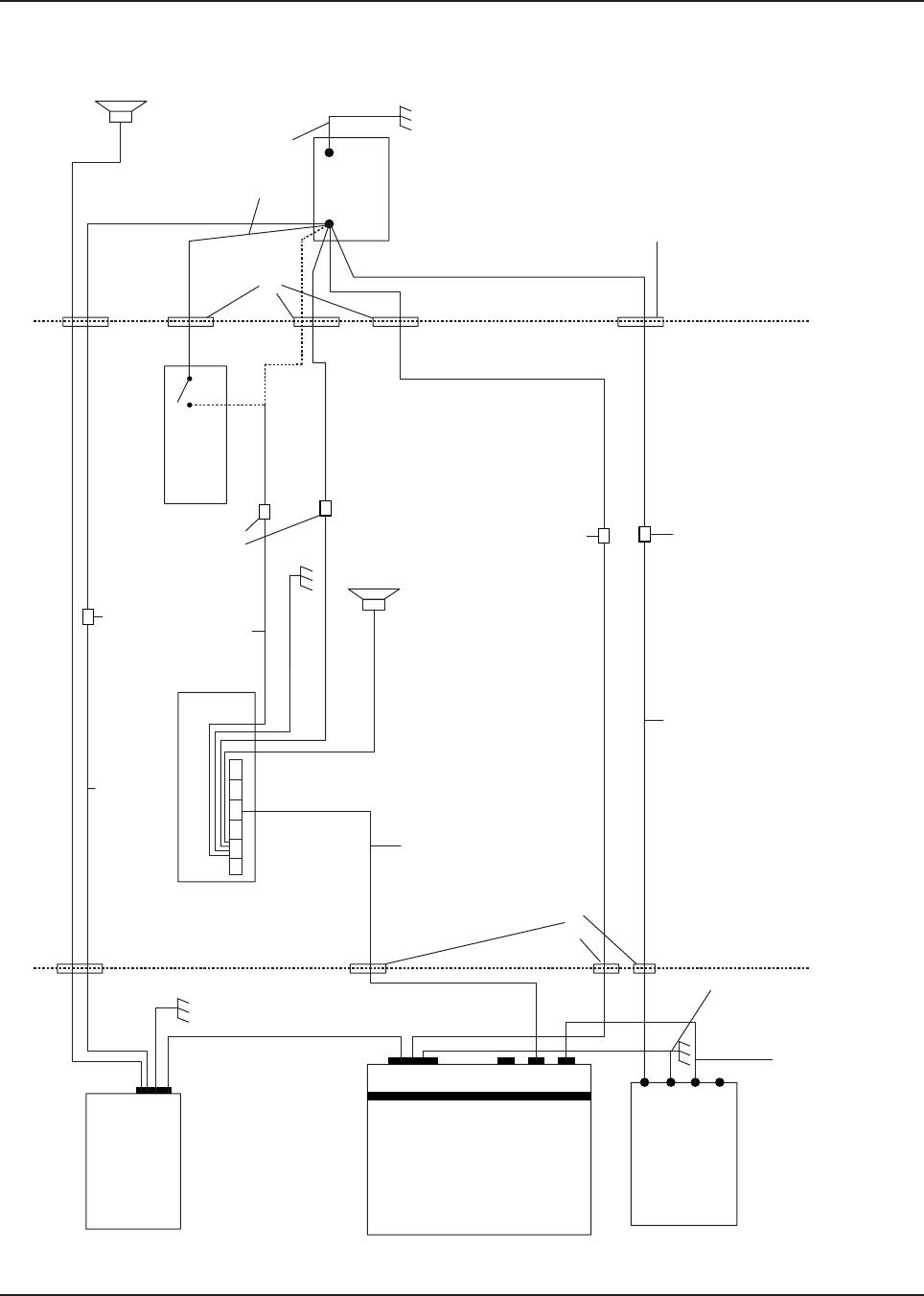
MN003109A01_aa
2-14 Standard Configurations Planning the Installation
RADIO COMPARTMENT
CAUTION OPERATOR COMPARTMENT VEHICLE BATTERY
COMPARTMENT
Siren Box (BLK)
A+
(Red)
A+
(Red)
15A Fuse
VEHICLE
IGNITION SWITCH
VEHICLE
BATTERY
PART OF
VEHICLE
WIRING
Siren Speaker
ON/ACC
3A OR 4A FUSE SEE NOTE
SPEAKER
RADIO POWER CABLE
(RED/BATTERY HOT)
15A, 20A OR
30A FUSE
16A Circuit Breaker
GROMMET
GROMMET
GROMMET
URC Controller
Box
Chassis GND
MMP to RJ45
Cable
TRANSCEIVER
TIB
CAN extension cable
A+
(Red)
IGN Sense
(yellow)
(BLK)
Control Head (Rear View)
Chassis GND
(+) (-)
Figure 2-22. Cabling Interconnect Diagram for 09 Remote Mount (URC is optional)
NOTE:
For remote mount configurations, do not supply IGNITION at the radio's rear accessory connector. See TABLE 2-2 for combinations of wiring the RED and YELLOW cables.
Alternator whine and other noise problems may occur. Isolate the RED cable with a Motorola Solutions relay (5900813674).
Draft

MN003109A01_aa
Standard Configurations Planning the Installation 2-15
2.1.3 Radio Operation Wiring for Dash and Remote Configurations
Determine from Table 2-1 or Table 2-2 the radio functionality you want to achieve, which is controlled
by the vehicle ignition switch state, the physical wiring of the radio ignition sense (ACC) wire, and by
the programmed CPS setting. For additional radio functionality as determined by the programming of
the ignition switch in CPS, refer to the HELP menu in your CPS that is Ignition as: Required, Blank,
Soft Power Off, TX Inhibit, PTT TX Inhibit, Ignition Only Power Up).
Choose a clean ignition point which is not shared in the immediate vicinity by other high current
accessories/devices to reduce the transients on the ignition line. Examples of
high-current accessories/devices are: Air Horn, relays, lightbars, and others. It is recommended to
wire to the vehicle ACC line, not the START or the solenoid side of the ignition circuit. Refer to
chapter 6 for best installation practices. The Ignition sense (ACC) cable uses either a 3-amp fuse
(6580283E01) or 4-amp fuse (6580283E02).
2.1.3.1 Dash Mount: Power, Ignition, and Emergency Cable Installation - Mid Power
The standard dash mount rear ignition sense cable HLN6863 contains a “thin red” ignition wire, a
jumper wire that shorts emergency to ground, and two gray wires attached to an external speaker
plug. The thin RED wire is the ignition sensed wire. Refer to Table 2-1 or Table 2- 2 for its correct
wiring configurations.
NOTE: This cable MUST be attached in order for the radio to operate in Dash mount, regardless of
how emergency is programmed in CPS or wired inside the vehicle. Either the emergency
jumper wire or an emergency accessory (footswitch or button) must be wired to the rear of the
transceiver in Dash mount. Otherwise, upon attachment of the radio power cable to the
vehicle battery, the radio incorrectly determines that emergency operation has been
activated, such as when an emergency footswitch is de-pressed and the emergency pin is
ungrounded.
Draft

MN003109A01_aa
2-16 Standard Configurations Planning the Installation
2.1.3.2 Remote Mount: Power, Ignition, and Emergency Cable Installation
The single control head O2, O5, O7 or O9 remote mount configurations receive power from the J200
connector red and black wires. The yellow wire at J200 is one ignition sense wire. The J2 connector
can also be used for ignition sense. If the HLN6863 is attached at J100 of the O2, O5, O7 or O9
control head, the “thin red” wire do NOT function as an ignition sense wire, since the J100 connector
has no ignition sense electrical connection.
NOTE: It is incorrect for installation to attach ignition sense at more than one wire or connector.
Refer to Table 2-1 or Table 2-2 for its correct wiring configurations.
The O3 control head receives its power down the CAN cable, and detects the ignition state by the
ignition sense pin at J2. The J2 connector can also be used for ignition sense.
In Multi-Control Head installations, the yellow ignition wire must be connected to the head assigned
ID # 1. Section 2.2.2.4: “Setting the Initial Control Head ID” for further information.
The design of the control head is different compared to the transceiver, therefore it is also NOT
necessary to attach HLN6863 at J100 to prevent accidental emergency operation. The control head
can have an emergency accessory attached at connector J100 instead of at the transceiver
connector J2. Wherever the emergency accessory is placed, it is recommended to only attach at one
location rather than multiple emergency accessories attached at different points of the radio.
Draft
MN003109A01_aa
Standard Configurations Planning the Installation 2-17
Table 2-1. Dash and Remote O2, O3, O5, O7 or O9 Radio Power ON @ J2
Dash/Remote
Mount
Transceiver
Red Power
Wire
HLN6863
Thin Red Wire
@ J2
Transceiver
Red Power
Wire
HLN6863
Thin Red Wire
@ J2
Transceiver
Red Power
Wire
HLN6863
Thin Red Wire
@ J2
Connected to
battery
XXX X
Connected to
ignition switch
XXX
Ignition switch
controls
No ignition switch control. Enables ignition switch functionality
as programmed in the codeplug.
Illegal wiring configuration. See
CAUTION note.
Table 2-2. Remote O2, O5, O7 or O9 Radio Power ON @ J200
Remote
Control Head
Red Wire
@J200
Control Head
Yellow Wire
@J200
Control Head
Red Wire
@J200
Control Head
Yellow Wire
@J200
Control Head
Red Wire
@J200
Control Head
Yellow Wire
@J200
Connected to
battery
XXX X
Connected to
ignition switch
XXX
Ignition switch
controls
No ignition switch control. Enables ignition switch functionality
as programmed in the codeplug.
Illegal wiring configuration. See
CAUTION note.
Table 2-3. Ignition Interface Cables
Part Number Description
HLN6863_ Cable, M.A.P. 26pin with Only Ignition and SPK
KT000274A01 Y-Cable, M.A.P to M.A.P. and DB 25
DO NOT connect any wires to the battery terminals until you have finished the entire
radio installation (Dash or Remote Mount) configuration to avoid potential equipment
damage.
Incorrect wiring of the radio may result in incorrect ignition sense detection, incorrect
power-on state, or incorrect power-off state of the radio system.
The Control Head Power cable wire (RED) and Transceiver Power cable wire (RED)
are always attached to the battery terminal and NOT to the ignition switch.
!
C a u t i o n
Draft

MN003109A01_aa
2-18 Standard Configurations Planning the Installation
2.1.4 Ignition Sense Switch (Radio Wide Advance)
CPS selectable settings to control the radio functionality based on the state of the vehicle Ignition
status. These descriptions can be found in the CPS (customer programming software) tool HELP
Guides and are repeated here for convenience.
Table 2-4. Ignition Sense Switch Settings in CPS
Feature Description
Blank • Radio POWERS ON when the Power Button is pressed or with the emergency power up
feature.
• Radio POWERS OFF when the Power Button is pressed.
TX Inhibit (Available only when: the radio is model/option capable)
• Radio POWERS ON with a radio Power On button / knob selection.
• Radio POWERS OFF with a radio Power Off button / knob selection, or when the Inactiv-
ity Auto Power Off timer expires.
•While “IGNITION” is not present, certain communications are not possible:
I. The radio does not register with ASTRO 25 (APCO) - Trunking Systems and there-
fore cannot receive this type of Trunking communications (see the System Type
field), however, Type II Trunking Systems can receive dispatch without being regis-
tered.
II. Also, the radio cannot be powered-on with the Emergency Power UP feature, and
Emergency Alarm transmissions using the Emergency Power UP footswitch are not
possible.
PTT TX Inhibit (Available only when: the radio is model/option capable)
• Radio POWERS ON with a radio Power On button / knob selection.
• Radio POWERS OFF with a radio Power Off button / knob selection, or when the Inactiv-
ity Auto Power Off timer expires.
•While “IGNITION” is not present, all PTT button transmissions are inhibited:
I. The radio does not register with ASTRO 25 (APCO) - Trunking Systems and
therefore cannot receive this type of Trunking communications (see the System
Type field), however, Type II Trunking Systems can receive dispatch without
being registered.
II. Also, the radio cannot be powered-on with the an Emergency Power UP
footswitch-press; however, the footswitch can be used to initiate Emergency
Alarm transmissions if the radio is already on.
Required • Radio POWERS ON when the Power Button is pressed and Ignition is present.
• Radio POWERS ON when Ignition is cycled and radio was previously ON.
• Radio POWERS OFF when the Power Button is pressed, or when Ignition is lost.
Soft Power Off • Radio POWERS ON when the Power Button is pressed, or when Ignition is detected.
• Radio POWERS OFF when the Power Button is pressed, or when Ignition is lost.
Ignition Only Power Up • Radio POWERS ON when Ignition is present.
• Radio POWERS OFF when Ignition is lost.
• Control head power button is ignored.
Draft

MN003109A01_aa
Standard Configurations Planning the Installation 2-19
NOTE: When either TX Inhibit, PTT TX Inhibit or Required are selected, the Emergency Power Up
feature is not be available to the radio-user.
When any other Ignition Switch setting is made, Emergency Power Up is available to the
radio-user, regardless of current ignition state.
Any optional inactivity time-out timer setting in CPS may delay the power off of the radio once
Ignition sense is removed.
Draft

MN003109A01_aa
2-20 Standard Configurations Planning the Installation
2.1.5 Motorola Solutions Branded SB9600 Siren/PA Configuration/Programming
The Siren/PA is shipped pre-wired for 100 W operation. It can be rewired for 65 W, 75 W, or 130 W
power levels.
To change to another power level, perform the following:
1. Open the Siren/PA connector cover to gain access to the two-connector speaker leads. Do
not change the speaker common lead (pin 20). The other lead is connected to pin 35 (for 100
W operation).
2. Using an appropriate pin removal tool, extract pin 35 and move it to one of the following pin
locations:
- pin location 36 for 75 W operation
- pin location 28 for 65 W or 130 W operation
3. For 65 W or 75 W operation, no further changes are required. Reassemble the connector.
4. For 130 W operation, you must parallel two 11 ȍ speakers, each rated at 65 W minimum.
Proper phasing of the two speakers is important--when connecting two speakers in parallel,
wire similar speaker terminals together to ensure maximum loudness and prevent
"deadspots." For example, if the terminals are marked "1" and "2", connect the terminals
marked "1" together and connect those wires to one speaker lead. Connect the terminals
marked "2" together and connect those wires to the other speaker lead.
5. When the Siren/PA is configured for dual speaker, 130 W operation, it is necessary to remove
a resistor and move two jumpers to set the correct power level. Remove the Siren/PA cover,
and locate resistor R219 (0 ȍ). This resistor should be removed for 130 W operation. Locate
jumpers JU100 and JU101. These jumpers should be installed for 130 W operation.
6. Close and reconnect the Siren/PA connector cover.
NOTE: Jumpers JU100 and JU101 do not affect the Siren output level. JU100 and JU101
compensate for the lower speaker load and the two speakers in parallel, by
decreasing the gain U102-1. JU100 affects the radio PA level and JU101 affects the
PA audio level.
Pin locations of various power level configurations are listed in Table 2-5
Before continuing, remember that under a high-line supply condition
(16.6 V), up to 30 % more power goes to the speaker(s) after
reconfiguring for 130 W operation. Do this only when your PA
speakers are capable of handling the extra power.
Table 2-5. Power Level Configurations
Pin location of speaker
leads R219 JU100/JU101
65 W 20,28 IN Across pins A and B
75 W 20,36 IN Across pins A and B
100 W 20,35 IN Across pins A and B
130 W 20,28 OUT Across pins B and C
!
C a u t i o n
Draft
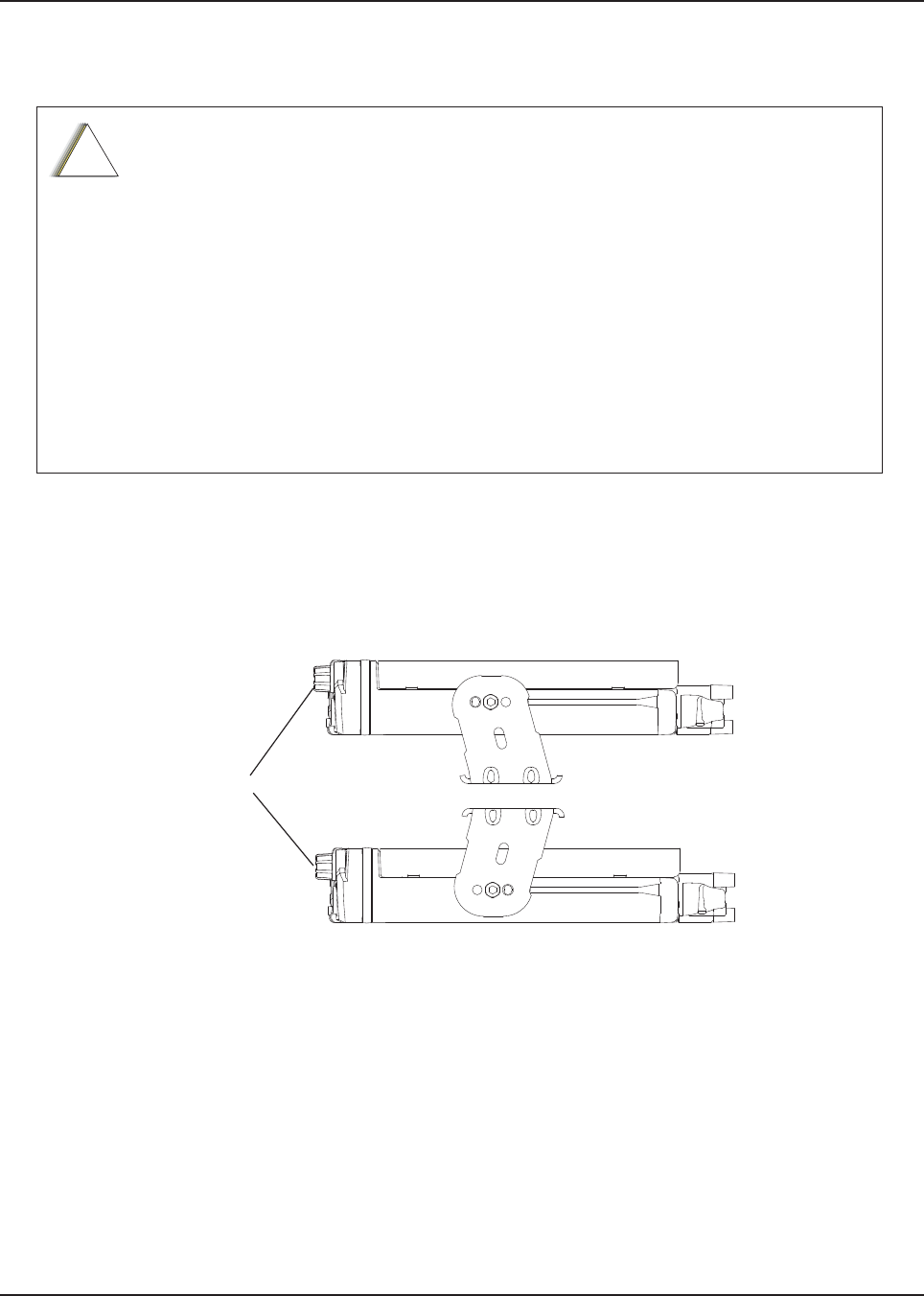
MN003109A01_aa
Standard Configurations Radio Mounting 2-21
2.2 Radio Mounting
The mounting location must be accessible and visible. Select a location that permits routing the RF
antenna cable as directly as possible.
NOTE: For optimum radio performance, orient the mounting trunnion as shown in Figure 2-23. For
new or existing installations of all use only the APX mobile trunnion, kit number HLN7002
(mid power) and HLN7003 (high power).
Figure 2-23. APX8500 Mid Power Trunnion Orientation
DO NOT mount the radio on a plastic mounting surface without first reinforcing the
mounting surface; the weight of the radio may crack or break the mounting surface.
DO NOT mount the radio on any surface where the radio could be partially submersed
in water. This is especially important if the cab area of the vehicle is cleaned by
spraying with water. If the radio sits in water for a length of time, moisture may seep
inside the radio and damage the electronic components.
DO NOT allow water to stand in recessed areas of vertically mounted radios. Remove
any moisture immediately to prevent it from seeping down into the radio.
Care must be taken to shield the control head (front and back) from direct exposure to
pressurized water. The pressurized water from a hose, in most cases, is more severe
than the stated test and conditions in typical environments.
!
C a u t i o n
RADIO
APPLIES TO RADIOS IN DASH AND REMOTE INSTALLATIONS
Draft

MN003109A01_aa
2-22 Standard Configurations Radio Mounting
NOTE: .
Figure 2-24. APX8500 High Power Trunnion Orientation
RADIO FRONT
APPLIES TO RADIOS IN REMOTE INSTALLATIONS
Draft
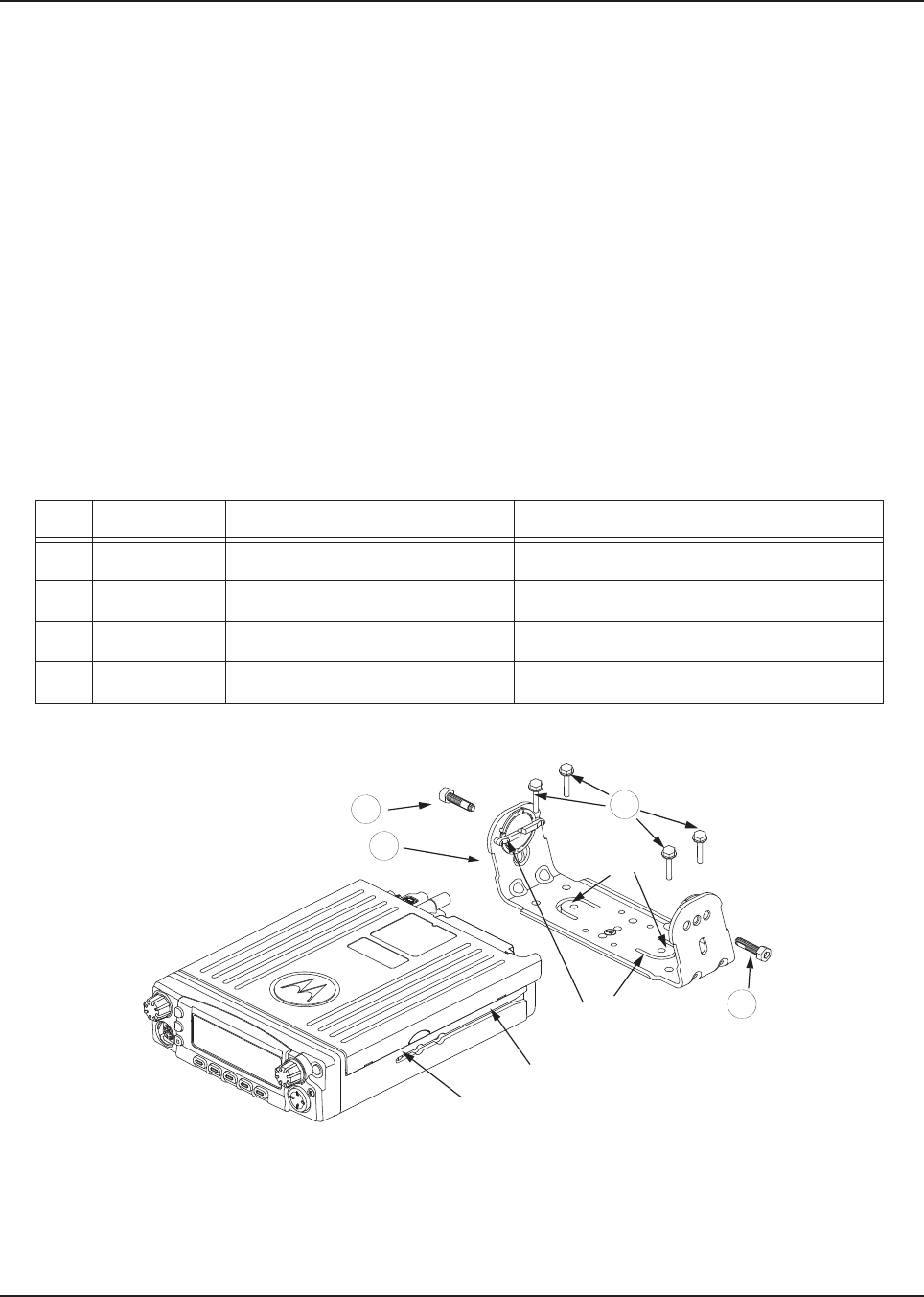
MN003109A01_aa
Standard Configurations Radio Mounting 2-23
2.2.1 Dash Mount with Trunnion - Mid Power
1. Select the location to mount your radio on the transmission hump (see Figure 2-25) or under
the dash (see Figure 2-26)
NOTE: When mounting the trunnion on the transmission hump take care that the transmission
housing is not affected. Plan your installation ensuring enough room for the Accessory
connector and cable in the back of the radio.
2. Using the trunnion mounting bracket as a template, mark the positions of the holes on the
mounting surface. Use the innermost four holes for a curved mounting surface such as the
transmission hump, and the four outmost holes for a flat surface such as under the dash.
3. Center punch the spots you have marked and realign the trunnion in position.
4. Secure the trunnion mounting bracket with the four self-drilling screws provided
(see Figure 2-25 and Figure 2-26).
5. Ensure that the plastic guides are aligned (horizontal) to the grooves of the trunnion. Slide the
radio into the grooves until it snaps into place (see Figure 2-26).
Figure 2-25. Below Dash Trunnion Mounting
Table 2-6. +LJKMid Power Trunnion Kit
Tabs
Threaded Hole
for Screw
Groove
Plastic
Guides
1
3
2
1
Item Part Number Description High/Mid Power Transceiver
1 0371859H01 Trunnion Mounting Screw APX 8500
2 0312002B14 Self-Drilling Tapping Screw APX 8500
3 HLN7002_ Mackinaw Trunnion Hardware Kit APX 8500
4HLN7003_ Mackinaw Trunnion Hardware Kit APX 8500
Draft
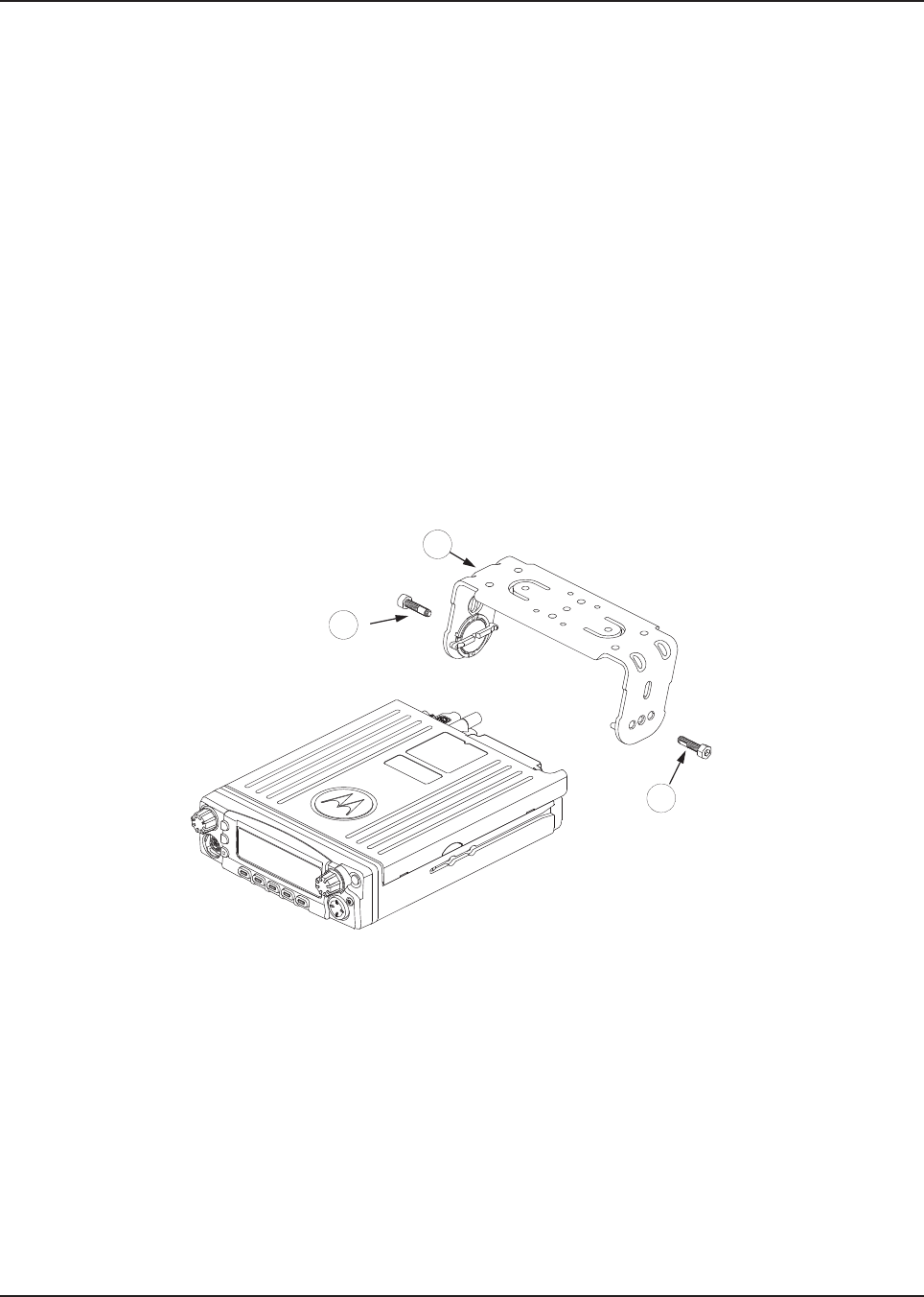
MN003109A01_aa
2-24 Standard Configurations Radio Mounting
Figure 2-26. Below Remote Trunnion Mounting
Figure 2-27. Transmission Hump Trunnion Mounting - Mid Power
1
1
3
Draft
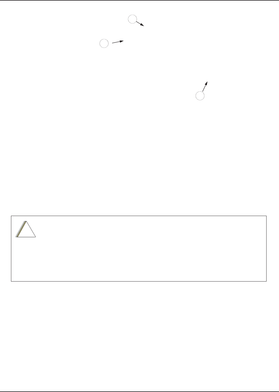
MN003109A01_aa
Standard Configurations Radio Mounting 2-25
Figure 2-28. Transmission Hump Trunnion Mounting - High Power
6. )RUPLGSRZHUUDGLRVecure the radio with two screws provided (Item 1 in Table 2-6). The torque
GRZQIRUFHIRU0371859H01 should be between 50 in-lbf to 52 in-lbf.
NOTE:This configuration shows the O5 control head. The TIB is used for O3 control head for the
same configuration.
2.2.2 Remote Mount with Trunnion
For a remote mount installation, the transceiver may be mounted anywhere in the vehicle, provided
that the installation location is safe, follows the cautions mentioned at the beginning of this section,
and is accessible for servicing/maintenance as well as cabling. A typical mounting location
recommended by Motorola Solutions is in the vehicle trunk. For mid power, the trunnion provided
may still be used to mount the transceiver, and the mounting process is the same as for the dash
mount installation (Section 2.2.1). See Figure 2-12 or Figure 2-14 for a remote installation.
The followings are the remote installation procedure for high power:
1. Select the location to mount your radio on the transmission hump ( see) or under the dash (see)
NOTE: When mounting the trunnion on the transmission hump ensure that the transmission housing
is not affected. Plan your installation ensuring enough room for the Accessory connector and
cable in the back of the radio.
Before installing any electrical equipment, check the vehicle manufacturer user
manual.
The installation of this device should be completed by an authorized servicer or
installer.
Before making any holes in the trunk for radio mounting, check the vehicle
manufacturer's user manual for restrictions such as due to the gas tank location.
1
1
3
!
C a u t i o n
Draft

MN003109A01_aa
2-26 Standard Configurations Radio Mounting
2. Using the trunnion mounting bracket as a template, mark the positions of the holes on the
mounting surface. Use the innermost four holes for a curved mounting surface such as the
transmission hump, and the four outmost holes for a flat surface such as under the dash.
3. Center punch the spots you have marked and re-align the trunnion in position.
4. Secure the trunnion mounting bracket with the four self-drilling screws provided (see and )
5. Ensure that the plastic guides are aligned (horizontal) to the grooves of the trunnion. Slide the radio
into the grooves until it snaps into place (see )
2.2.2.1 Remote Mount Control Head Installation
Choose a mounting location for the radio, considering accessibility, and control and antenna cable
lengths.
The recommended mounting surfaces for the control unit are under the mounting surface, on the
transmission hump, or on the center console. Figure 2-29 and Figure 2-30 shows how the trunnion,
control head, and cables should be installed for the O2, O3, O5, O7 or O9 control head.
NOTE: Connector-protective covers (Remote Mount Dust Cover kit) KT000246A01 are provided with
the radio.
They should be installed on exposed connectors for added environmental robustness.
Draft
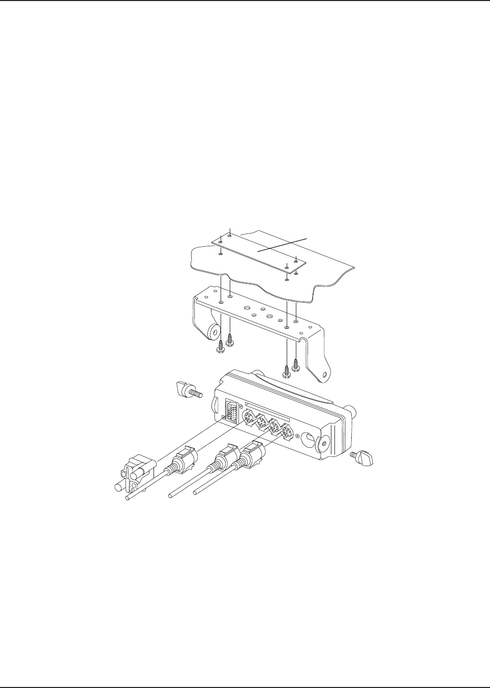
MN003109A01_aa
Standard Configurations Radio Mounting 2-27
An adjustable trunnion, which allows a number of mounting positions, is supplied for mounting the
control unit. The installation must not interfere with the operation of the vehicle or its accessories, nor
disturb passenger seating or leg room. The control head must be within convenient reach and
viewing of the user.
If the trunnion is mounted on a plastic mounting surface, all four mounting screws should penetrate
the mounting surface supporting metal frame. If that is not possible, use a metal backing plate (not
supplied) to strengthen the installation. The followings are the installation procedure:
1. Use the control unit trunnion as a template to mark the mounting holes; drill 5/32" holes.
If mounting on a plastic surface, use a metal backing plate.
2. Attach the trunnion bracket using all four 10-16" x 5/8" self-tapping screws provided.
3. Temporarily install the control head (adjusting for proper viewing angle) and fasten it to the
trunnion with two wing screws. Test the installation to be sure the control head feels securely
locked in place while you are pressing its buttons.
4. Finish installation by fully tightening screws.
Figure 2-29. O5 Control Head Installation Exploded View (Also applicable for O2 and O7 Control Heads)
Metal Backing Plate
(Not Supplied)
Draft
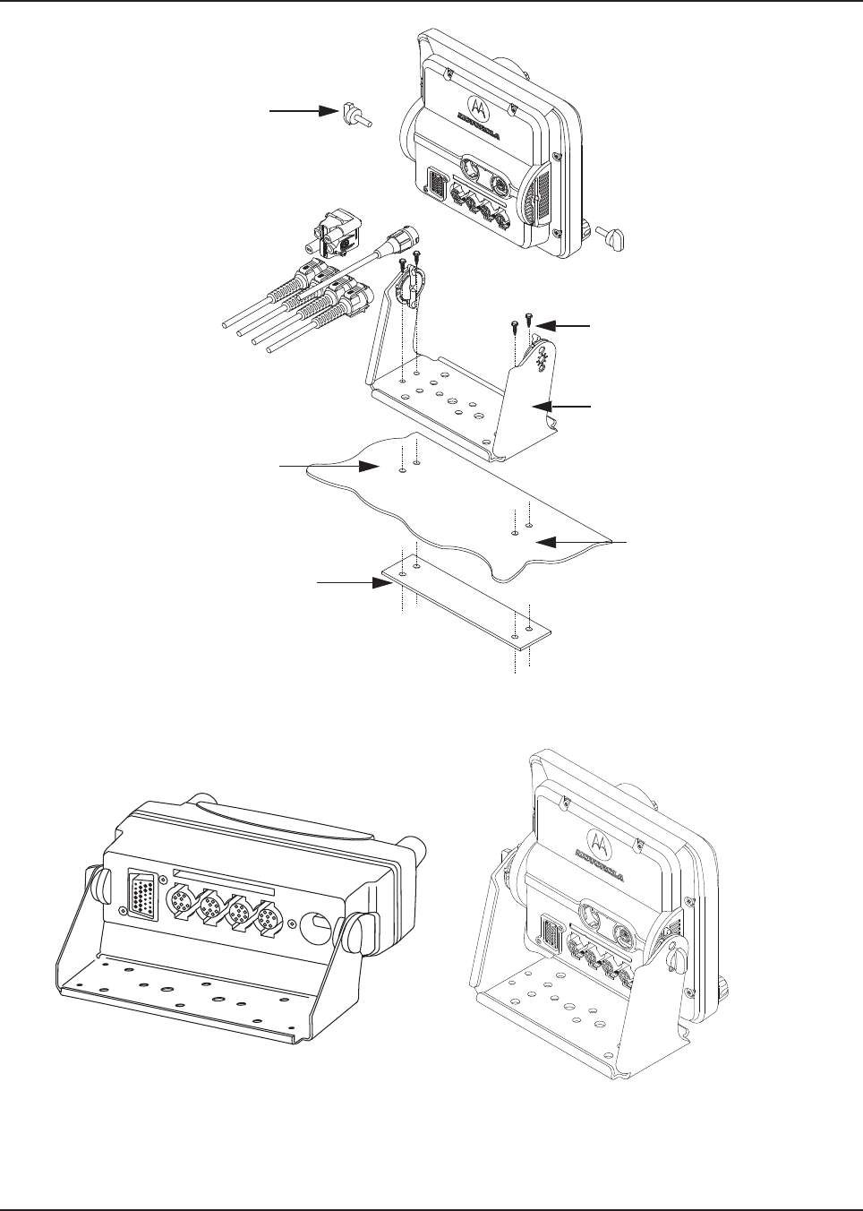
MN003109A01_aa
2-28 Standard Configurations Radio Mounting
Figure 2-30. O9 Control Head Installation Exploded View
Figure 2-31. O5 and O9 Control Head Rear View
Adjust the control head to desired
angle and secure with wing screws
Use four mounting screws on all
installations
Trunnion
Drill four 5/32” holes in
mounting surface
Mounting surface
IMPORTANT:
Use a metal backing plate (not
supplied) if mounting trunnion on
plastic or unstable surface
Draft
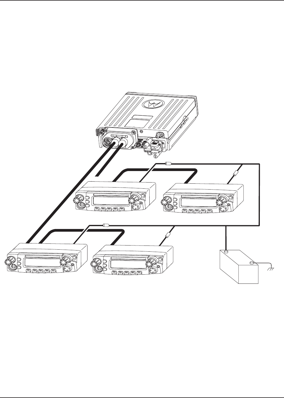
MN003109A01_aa
Standard Configurations Radio Mounting 2-29
2.2.2.2 Multiple Control Head Installation
Control heads in a multiple control head configuration should be installed per the steps detailed in
Section 2.2.2.1: “Remote Mount Control Head Installation” . Two heads can be connected to each of
the two CAN connectors on the transceiver, see Figure 2-32. Control heads can also be connected a
“daisy chain” configuration from a single transceiver CAN connector. See Figure 2-34 for examples.
NOTE: The transceiver must be configured for Multiple Control Head through CPS programming.
Navigate to the “Control Head” tab in the Radio Wide section of CPS, and select “Help” for
further information and tutorials.
Figure 2-32. Multiple Control Heads Parallel Configurations - Mid Power
Control Head 1 Control Head 2
J300R J300R
J200 J200
J300L
(-)
RED LEAD
(+)
BATTERY
FUSE
FUSE
FUSE
FUSE
Control Head 3 Control Head 4
J300R
J200 J200
J300L
J300R
Draft

MN003109A01_aa
2-30 Standard Configurations Radio Mounting
Figure 2-33. Multiple Control Heads Parallel Configurations - High Power
Draft
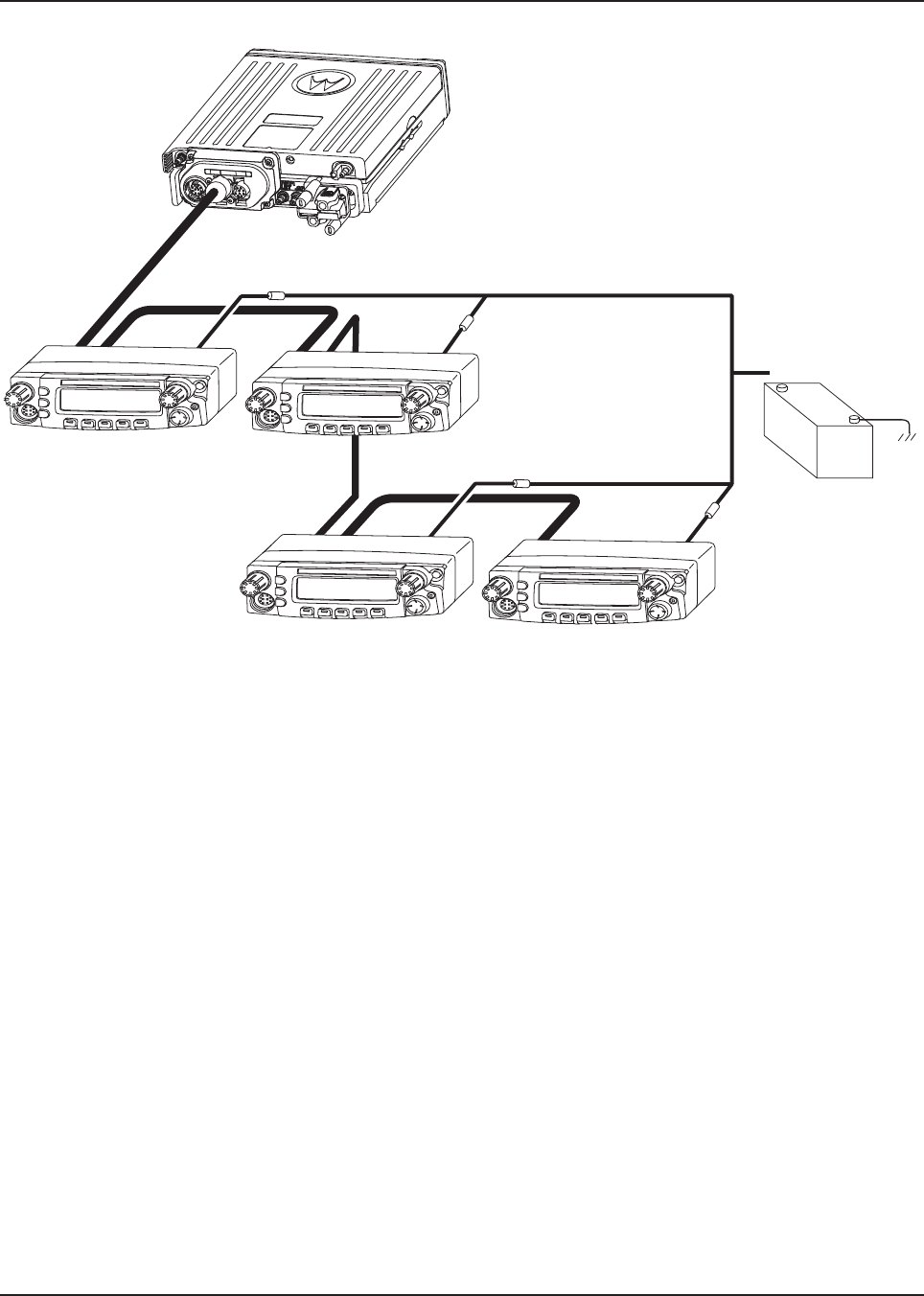
MN003109A01_aa
Standard Configurations Radio Mounting 2-31
Figure 2-34. Multiple Control Heads Series Configurations - Mid Power
Control Head 1 Control Head 2
J300R J300R
J200 J200
J300L J300L
(-)
RED LEAD
(+)
BATTERY
FUSE
FUSE
FUSE
FUSE
Control Head 3 Control Head 4
J300R
J200 J200
J300L
J300R
Draft

MN003109A01_aa
2-32 Standard Configurations Radio Mounting
Figure 2-35. Multiple Control Heads Series Configurations - High Power
NOTE: In Multiple Control Head (MCH) installations, the yellow ignition sense wire must be
connected to the head assigned ID # 1. Section 2.2.2.4: “Setting the Initial Control Head ID”
for further information.
Use the most convenient configuration for your installation, ensuring that the combined cable lengths
do not exceed 131 feet (40 meters). See Tab l e 2 -7 for a list of available CAN cable lengths. Control
head ground, power and ignition sense wires (black, red, and yellow respectively) may need
additional length (not supplied) in installations that locate the head more than 10 feet from a power
source.
Table 2-7. Available CAN Cables
Part Number Description
HKN6164_ Cable, Remote Mount, 40 m (131 ft)
HKN6165_ Cable, Remote Mount, 35 m (115 ft)
HKN6166_ Cable, Remote Mount, 23 m (75 ft)
HKN6167_ Cable, Remote Mount, 15 m (50 ft)
HKN6168_ Cable, Remote Mount, 9 m (30 ft)
HKN6169_ Cable, Remote Mount, 5 m (17 ft)
HKN6170_ Cable, Remote Mount, 3 m (10 ft)
Draft
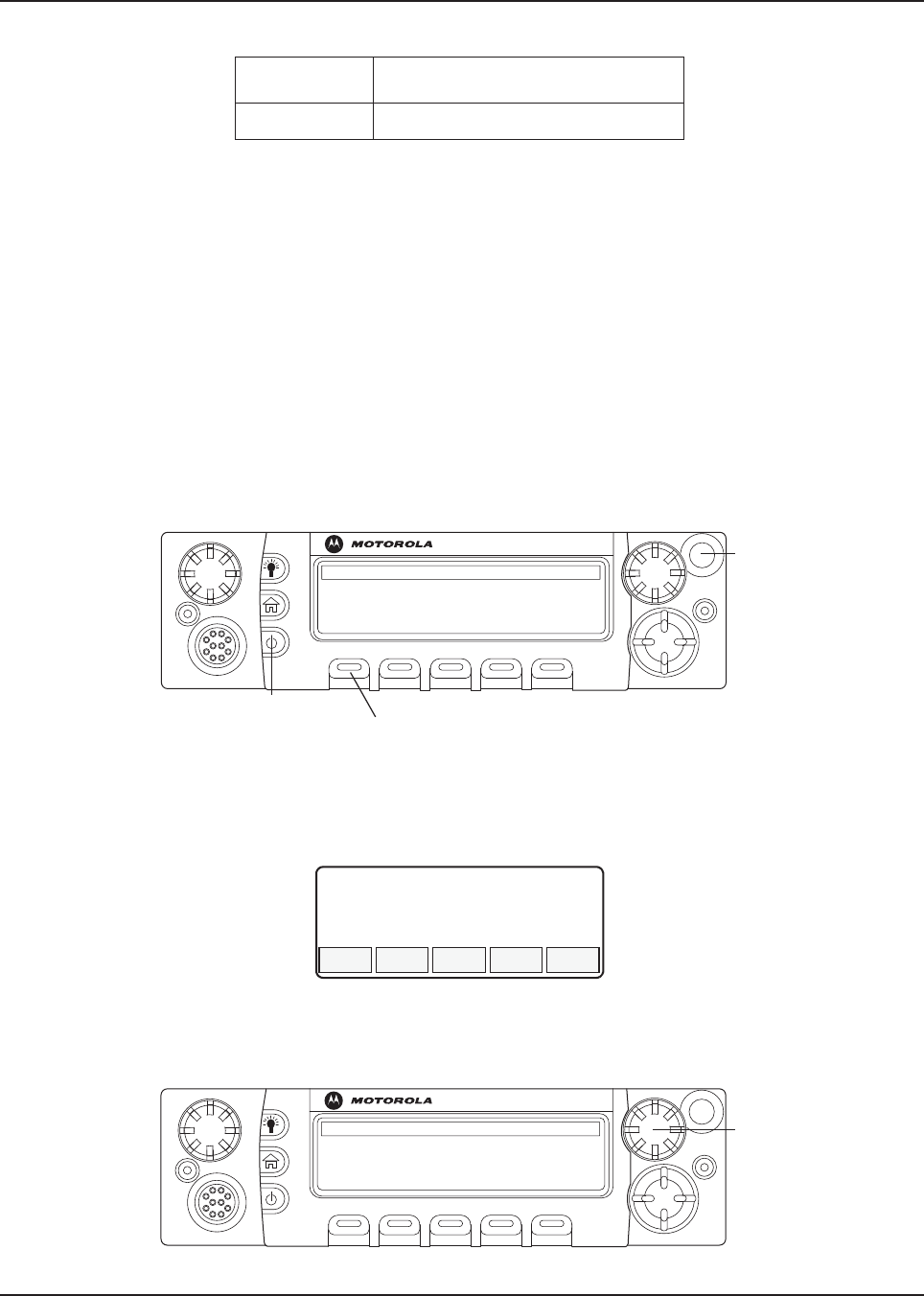
MN003109A01_aa
Standard Configurations Radio Mounting 2-33
2.2.2.3 Cable Installation
Route the cables where they are protected from pinching, sharp edges or crushing. Use grommets in
any holes where the cable passes through metal panels. Figure 2-20 shows how the cables and
components are connected. It is not recommended to route cabling or wiring inside the wheel wells
of a vehicle.
2.2.2.4 Setting the Initial Control Head ID
The Front Panel Programming (FPP) mode allows you to define which control head in a Multi Control
Head system becomes control head number 1-4.
Set the control head ID number for each attached head the first time Multi Control Head is used.
1. Press the power button to power off the radio.
2. Press and hold left-most menu and the orange button on the control head simultaneously.
Figure 2-36. APX Mobile O5 Control Head Front View
3. Press the power button to power on the control head. The head powers on into FPP mode
and display the current control head ID number:
Figure 2-37. Radio Display with Current Control Head ID
4. Turn the Mode knob to change the control head ID number.
PMLN4958_ Cable, O3 Extension, 5 m (17 ft)
Table 2-7. Available CAN Cables
Part Number Description
O5
Left-most
Menu Button
Power Button
Emergency
Button
CH ID#
1
O5
Mode Knob
Draft
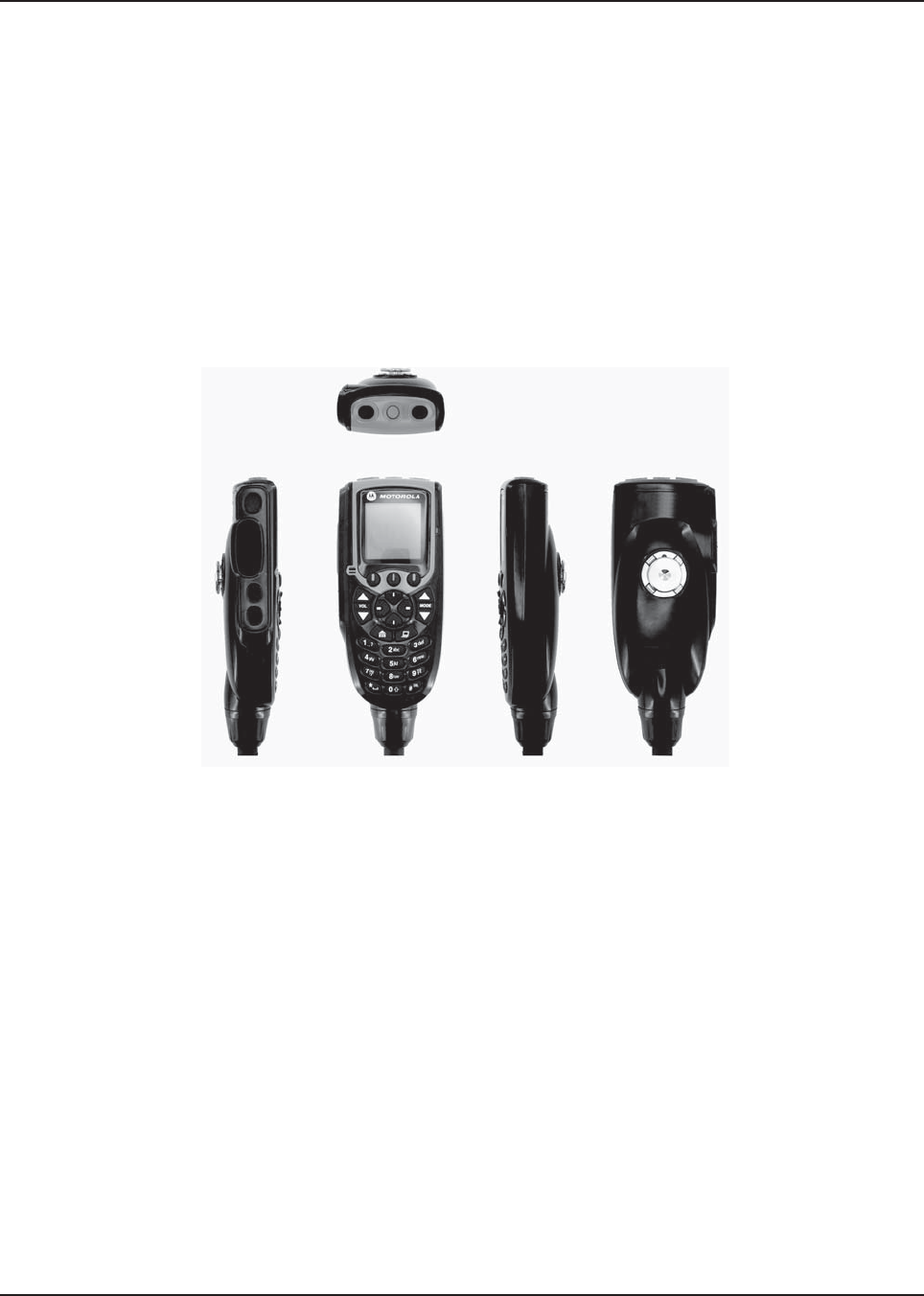
MN003109A01_aa
2-34 Standard Configurations Radio Mounting
Figure 2-38. APX Mobile O5 Control Head Front View – Mode Knob
5. Repeat steps 1 to 4 above to set the ID of the remaining control heads.
NOTE: In Multiple Control Head (MCH) installations, the yellow ignition sense wire must be
connected to the head assigned ID # 1.
2.2.2.5 O3 Control Head and Remote Mount Cabling
Choose a mounting location for the radio, considering accessibility, and control and antenna cable
lengths. The control head extension cable and the accessories cable should be installed and routed
properly to avoid complications. Route the cables in the vehicle wiring troughs (where available) or
route the cables where they are protected from pinching, sharp edges, or crushing. One suggested
route is along one side of the driveshaft hump under the carpet. Use grommets in any holes where
the cable passes through metal panels.
Figure 2-39. O3 Control Head
The recommended mounting surface for the control unit is on the center console. Figure 2-41 shows
how the hang-up clip control head, and cables should be installed for the O3 control head.
NOTE: Connector-protective covers are provided with the radio. They should be used for added
environmental robustness.
A mounting clip, which allows the control head to be mounted, is supplied together with the control
head. The installation must not interfere with the operation of the vehicle or its accessories, nor
disturb the passenger seating. The control head must be within convenient reach and viewing of the
user.
Install the mounting clip as follows:
1. Use the provided mounting clip to determine the location of the two screw holes.
2. Drill 7/16” deep holes for upper and lower screws.
3. Use the tapping screw provided to install the mounting clip.
Top
Front RightLeft Back
Draft
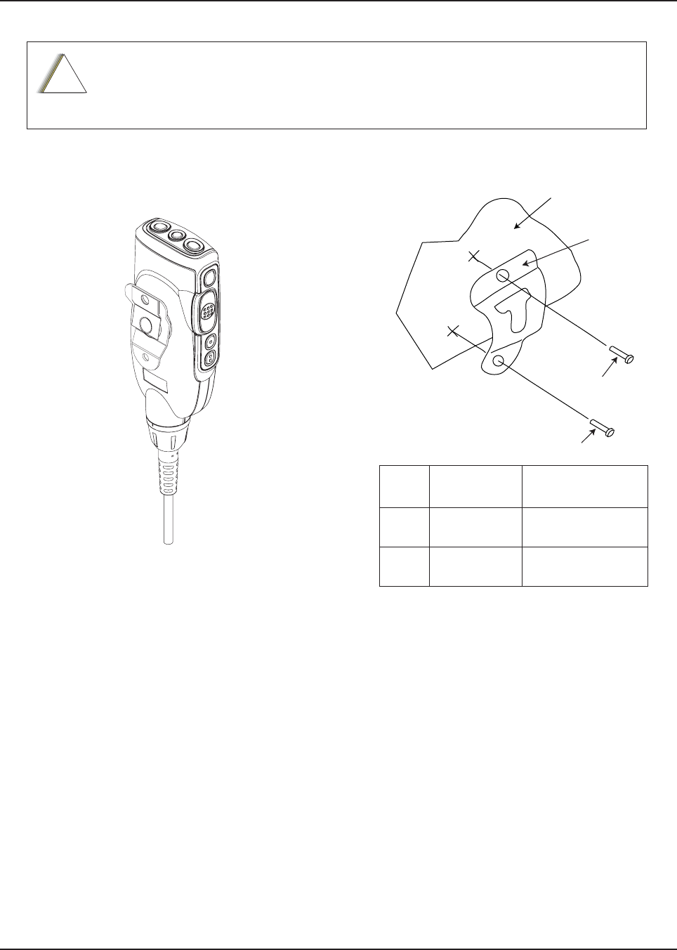
MN003109A01_aa
Standard Configurations Radio Mounting 2-35
Care must be taken to shield the control head (front and back) from direct exposure to
pressurized water. The pressurized water from a hose, in most cases, is more severe
than the stated test and conditions in typical environments.
Figure 2-40. O3 Control Head Rear View Figure 2-41. Hang-Up Clip Installation Exploded
View
!
C a u t i o n
VEHICLE
DASHBOARD
2
2
1
2
2
1
Vehicle Mounting Surface
Item
No.
Part Number Description
1 01-80743T91 Mic Hang-Up Clip
Assembly
2 03-07644M19 Screw, Machine,
8-32 x 7/16
Draft
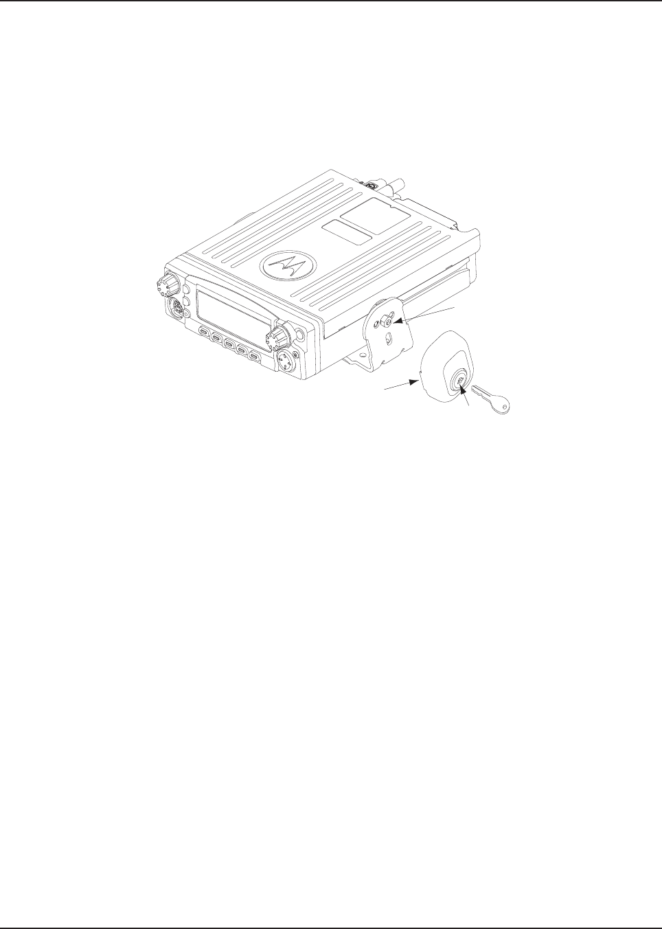
MN003109A01_aa
2-36 Standard Configurations Radio Mounting
2.2.3 Locking Kit (Optional) - Mid Power
2.2.3.1 All Radios
If an optional locking kit (HLN6372_) is used (shown in Figure 2-42), position the lock housing on the
trunnion after installing the radio mounting screws. Then rotate the lock with the key in it and remove
the key to lock the radio. You can install the lock on either side of the radio, and in dash and remote
mount installations.
Figure 2-42. Locking Kit (Optional)
Lock
Lock
Housing
Existing
Mounting
Screw
Draft
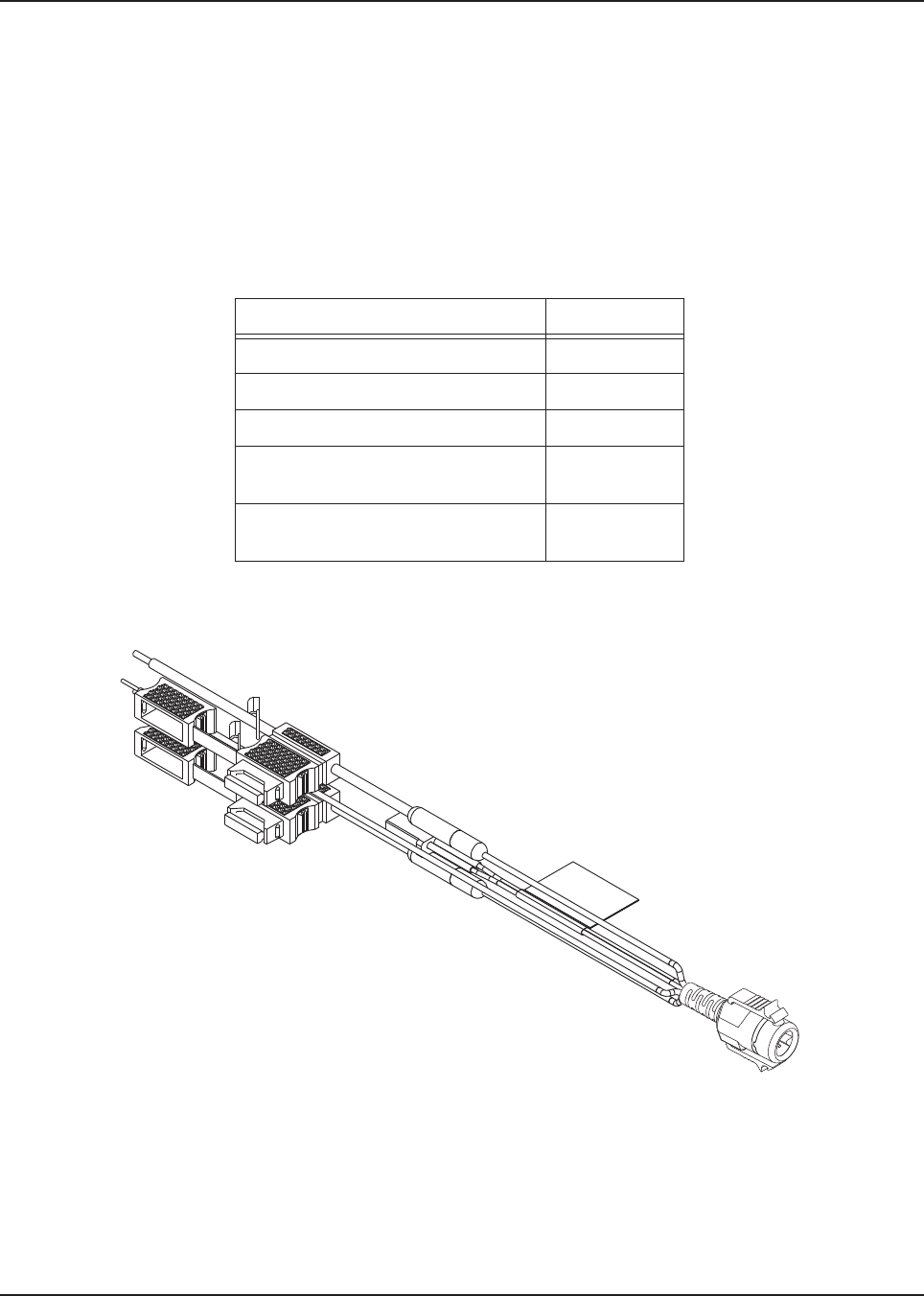
MN003109A01_aa
Standard Configurations Power Cables (Transceiver and Control Head) 2-37
2.3 Power Cables (Transceiver and Control Head)
Route the RED power cable from both the radio and the control head to the vehicle battery
compartment, using accepted industry methods and standards. Be sure to grommet the firewall hole
to protect the cable. Remove the 15-amp (part number 6580283E06), 20-amp (part number
6580283E07) or 30-amp (part number 6580283E09) fuse from the fuseholder and connect the red
lead of the radio power cable to the positive battery terminal using the hardware provided as shown
in Figure 2-43 and Figure 2-44. Connect the black lead to a convenient solid chassis ground point.
DO NOT connect the black lead directly to the battery negative terminal.
2.3.1 O2, O5, O7 or O9 Control Head Power Cables
Figure 2-43. HKN6188_ Power Cable with External Speaker Connector
Table 2-8. Power Cables
Description Part Number
Mid Power Dash Mount HKN4191_
Mid Power Remote Mount HKN4192_
High Power Remote Mount HKN6110
O5, O7, and O9 Remote Control
Head Power Cable - Mid Power
HKN6188_
O5, O7, and O9 Remote Control
Head Power Cable - High Power
HKN6188_ or
HKN6188_
Draft
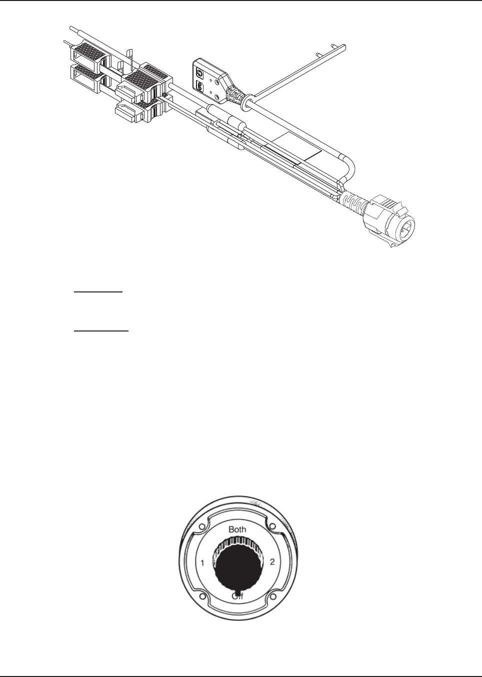
MN003109A01_aa
2-38 Standard Configurations Power Cables (Transceiver and Control Head)
Figure 2-44. HKN6187_ Power Cable with External Speaker Connector, Record Audio Output Jack (2.5 mm)
and Earphone Jack (2.5 mm)
NOTE: Audio Out – Does not require CPS programming. Attaching a headset mutes the external
speakers of the radio which are attached at the SPK jack of the control head.
Record Out – Requires CPS programming. In CPS, navigate to Radio Wide/Advanced/
Record Audio and select TX + RX Audio.
2.3.2 Battery Selector Switch
In vehicles which have installed a Battery Selector Switch, the ignition sense (yellow) wire should be
the only wire connected to the battery selector switch (see Figure 2-45). Radio transceiver and
control head power wires (red) must be connected directly to the vehicle battery. If the control head
power wire and the control head ignition sense wire are both connected to a battery selector switch,
but the radio transceiver power lead is not, improper power-cycling and off-state battery drainage
may occur. If the desired state of the radio is a total battery drain elimination, then all power and
ignition sense wires must be routed through the battery selector switch, so that the control head and
radio transceiver both see the loss of battery power at the same time.
Figure 2-45. Battery Selector Switch
Draft

MN003109A01_aa
Standard Configurations Antenna Installation 2-39
2.4 Antenna Installation
IMPORTANT: To assure optimum performance and compliance with RF Energy
Exposure regulations, these antenna installation guidelines and
instructions are limited to metal-body vehicles with appropriate ground
planes and take into account the potential exposure of back seat
passengers and bystanders outside the vehicle.
2.4.1 Selecting an Antenna Site/Location on a Metal Body Vehicle
1. External installation – Check the requirements of the antenna supplier and install the
vehicle antenna external to a metal body vehicle in accordance with those requirements.
2. Roof top – For optimum performance and compliance with RF Energy Exposure regulations,
mount the antenna in the center area of the roof.
3. Trunk lid – On some vehicles with clearly defined, flat trunk lids, the antennas of some radio
models (see restrictions below) can also be mounted on the center area of the trunk lid. For
vehicles without clearly defined, flat trunk lids (such as hatchback autos, sports utility
vehicles, and pick-up trucks), mount the antenna in the center area of the roof.
Before installing an antenna on the trunk lid,
- Be sure that the distance from the antenna location on the trunk lid is at least 85 cm (33
inches) from the rear seat head-rest to ensure compliance with RF Energy Exposure regu-
lations.
- Ensure that the trunk lid is grounded by connecting grounding straps between the trunk lid
and the vehicle chassis.
4.Mounting restrictions for certain radio models.
NOTE:Do not cut antenna cables to ensure compliance with RF Energy Exposure regulations
NOTE: 9+)DQG8+)ZDYHDQWHQQDVDQGDOO9+)DQG8+)DQWHQQDVWUDQVPLWWLQJDERYH
:VKRXOGEHPRXQWHGRQWKHURRI/2&DQG/2&LQ)LJXUH$OO%DQGDQWHQQD
VKRXOGEHPRXQWHGRQO\LQWKHFHQWHUDUHDRIWKHURRIQRWRQWKHWUXQNOLGWRHQVXUH
FRPSOLDQFHZLWK5)(QHUJ\([SRVXUHUHJXODWLRQV
5. Ensure that the antenna cable can be easily routed to the radio. Route the antenna cable as
far away as possible from any vehicle electronic control units and associated wiring.
6. Check the antenna location for any electrical interference.
NOTE: Any two metal pieces rubbing against each other (such as seat springs, shift levers, trunk and
hood lids, exhaust pipes, and others in close proximity to the antenna can cause severe
receiver interference.
If these conditions cannot be satisfied, then mount the antenna on the roof top.
!
C a u t i o n
Draft
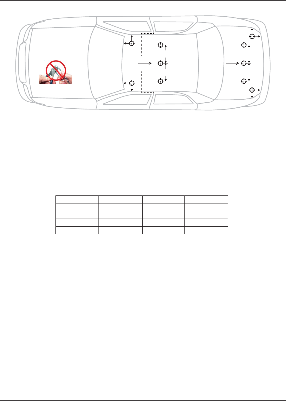
MN003109A01_aa
2-40 Standard Configurations Antenna Installation
Figure 2-46. Multiple Antennas Separation for locations 1-10
Figure 2-46 indicates the separation distances required for the various antennas used with an APX
8500 radio. Each "cross-hair" symbol represents a possible location, that is LOC of an antenna. The
recommendation is to locate them as close to the center of the roof and/or trunk as possible, without
interference with a lightbar. This picture is not drawn to scale.
For letters A, B, C, and D, the table indicates the EXACT distance for separation of the LMR
antennas.
For letters E, F, G, and H, the table indicates the maximum distance between the edge of the ground
plane and the accessory antenna (BT/WLAN, LTE or GPS) location.
NOTE:
• A minimum of 18 inch separation is required between lightbar and any roof mounted antennaH,
to prevent interference with the lightbar circuitry (see lightbar manufacturers installation
information).
• The LMR 700/800 antennaH should only be placed at LOC:2 or LOC:5.
• Standard LMR VHF and UHF antennaH should only be placed at LOC:1, LOC:3, LOC:4 and
LOC:6.
• 1/4 wave LMR VHF and UHF antennaH DQGDOO9+)DQG8+)DQWHQQDHWUDQVPLWWLQJDERYH
:should only be placed at LOC:1 and LOC:3 (i.e.roofonly) to ensure compliance with RF
Energy Exposure regulations.
• The VML antenna must be separated from any LMR antenna by at least 40 inches.
• The LTE Main and Diversity Antenna locations should be at LOC:9 and LOC:10 when the LMR
All-Band or LMR 700/800 narrow band antennaH are at LOC:2 (i.e LTE opposite location from
the LMR).
• The LTE Main and Diversity Antenna locations should be at LOC:7 and LOC:8 when the LMR
All-Band or LMR 700/800 narrow band antennas are at LOC:5 (i.e LTE opposite location from
the LMR).
• In some mobile installations that include an LTE modem, external filtering on the LMR portand/
or the LTE port may be needed to reduce interference. Contact your local MotorolaSolutions
Service Center for more information and for filter kit numbers (See Appendix forcontact info).
Table 2-1 Distance Between Antenna
Characters Distance Characters Distance
A 8 inches E 8 inches
B 8 inches F 8 inches
C 8 inches G 8 inches
D 8 inches H 8 inches
F
F
E
G
C
D
G
H
H
E
LOC:7 LOC:1
LOC:2
LOC:3
A
B
LOC:8
LOC:9
LOC:4
LOC:5
LOC:6
LOC:10
Roof
Center
Trunk
Center
NOTE: Do not cut
the antenna cable
Draft
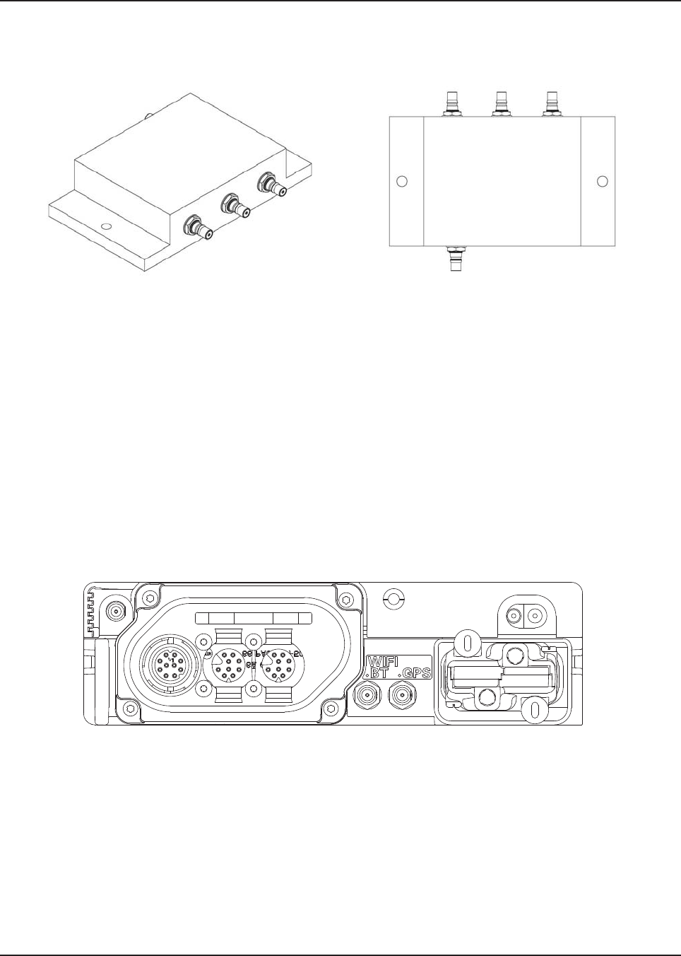
MN003109A01_aa
Standard Configurations Antenna Installation 2-41
2.4.2 Multiplexers and Vehicle Installation
Figure 2-47. Multiplexer Views
2.4.3 QMA Connection (APX 8500 Only)
APX8500 is using a quick disconnect connection called QMA. This does not require any tightening.
• Ensure there is sufficient slack in the antenna cable.
• Ensure that the collar of the antenna cable plug does not bind.
• Engage the QMA cable plug onto the jack, listening for a click to ensure proper engagement.
• Gently tug on the cable to ensure that it is engaged.
• To disengage, pull back on the cable plug collar and pull the cable straight off the jack.
2.4.4 GPS/GLONASS/Wi-Fi/Antenna Placement (APX 8500 Only)
Figure 2-48. GPS/GLONASS and Wi-Fi Antenna Connector on the Radio
Draft
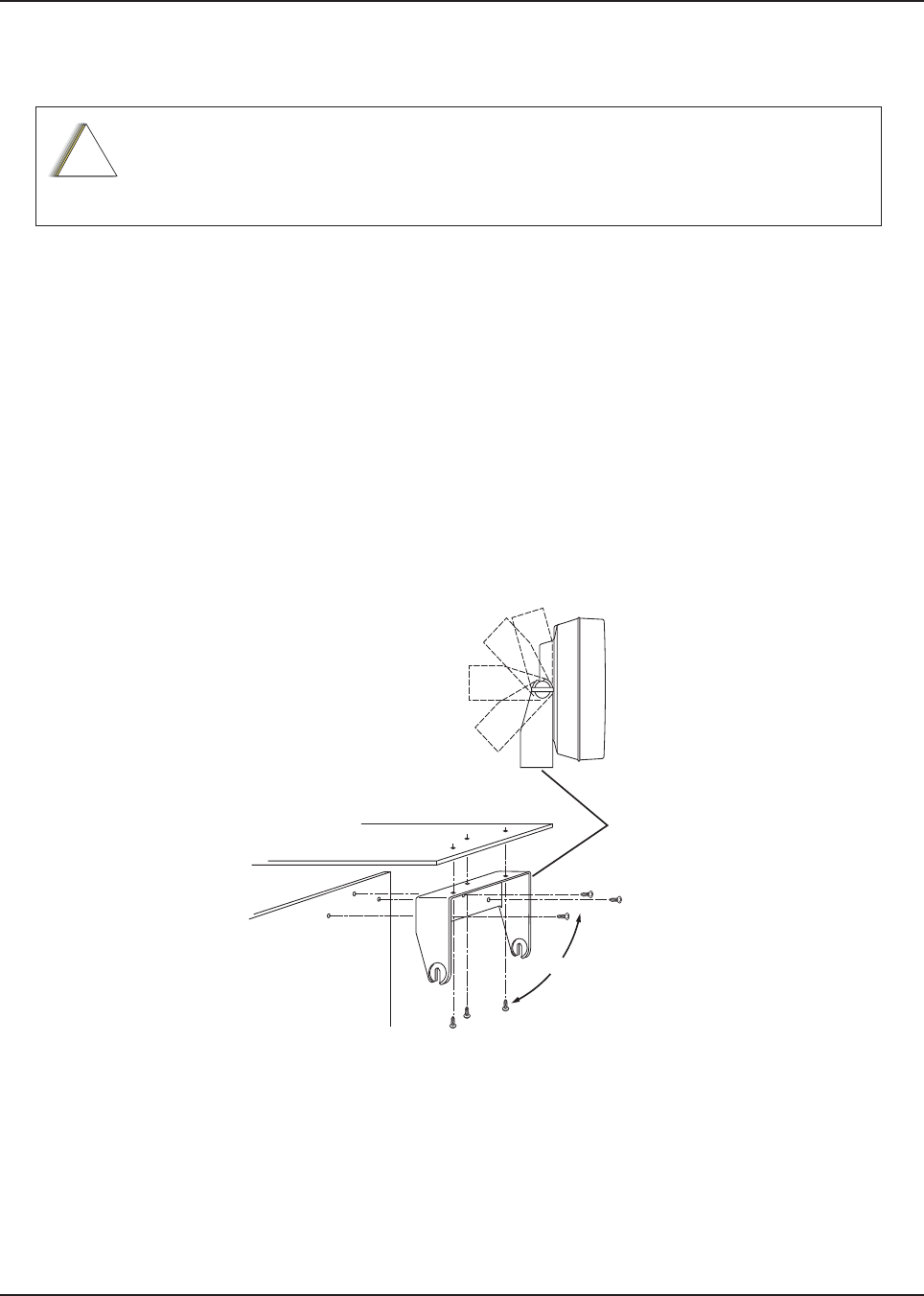
MN003109A01_aa
2-42 Standard Configurations Speaker
2.5 Speaker
The speaker kit includes a trunnion bracket that allows the speaker to be mounted in a variety of
ways. With the trunnion bracket, the speaker can mount permanently on the mounting surface or in
accessible firewall areas. The trunnion allows the speaker to tilt for best operation. Mount the
speaker out of the way so that it is not kicked or knocked around by the vehicle occupants. Mount the
speaker as follows:
1. Use the speaker mounting bracket as a template to mark the mounting hole locations.
2. Use the self-drilling screws provided to fasten the trunnion.
3. Attach the speaker and fasten to the trunnion with two wing screws.
4. Route the speaker wires under the carpet or floor covering, or behind the kick panels. Be sure
the wires are out of the way and is not snagged and broken by the occupants of the vehicle.
5. Do not submerse the 2-pin speaker connector in water nor place this connector in an area
that could have standing water.
Figure 2-49. Speaker Mounting
DO NOT ground the radio's speaker leads. This system has a floating speaker output
(DC voltage on both leads); damage to the audio circuit results if either lead is
grounded or if they are shorted together.
!
C a u t i o n
Dashboard
Firewall
Trunnion
Bracket
OR
Draft
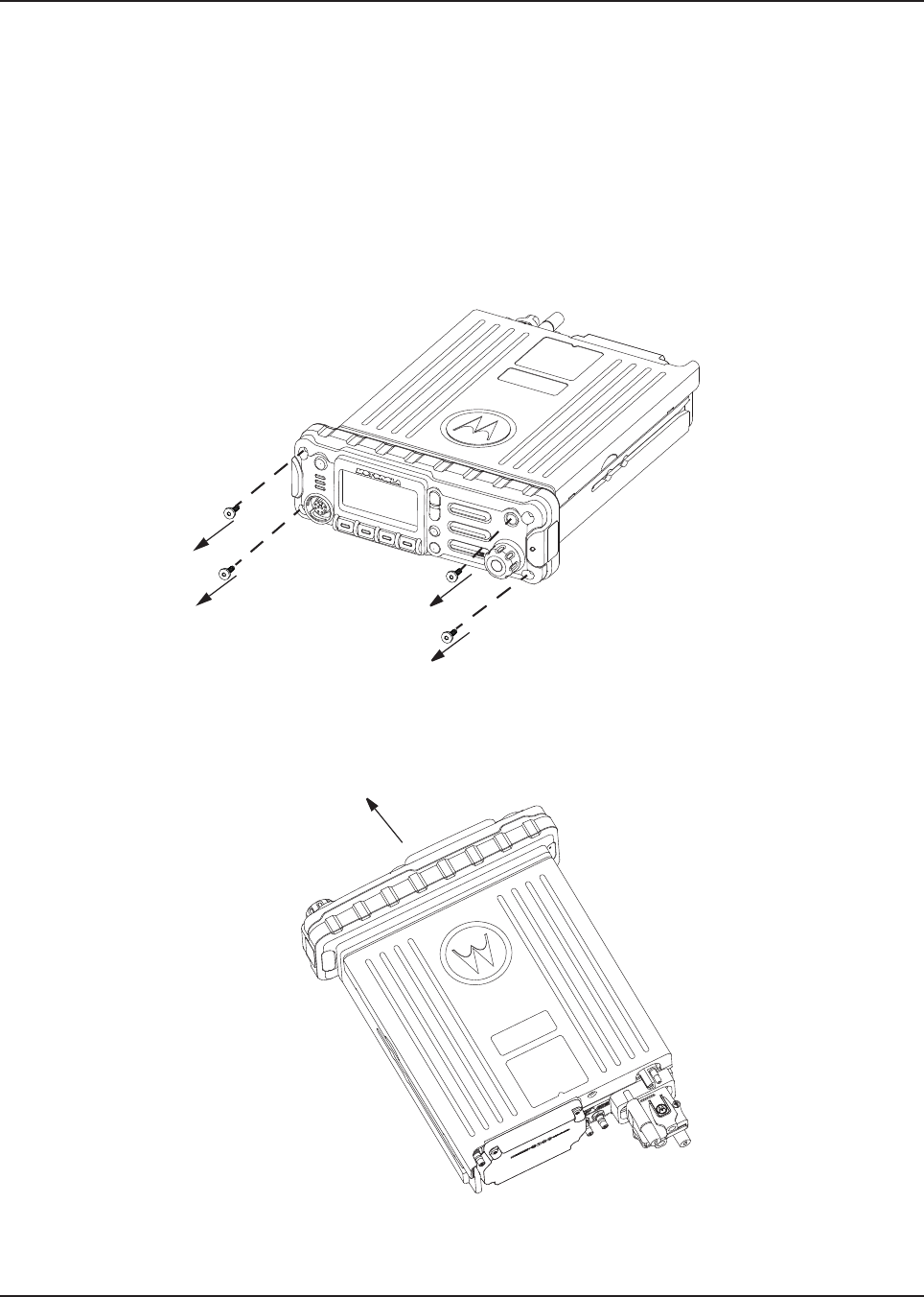
MN003109A01_aa
Standard Configurations Speaker 2-43
2.5.1 Internal Speaker Disassembly
NOTE: This configuration is only applicable for O2 Control Heads.
You can disable the internal speaker of your radio by following the instructions below.
The followings are the procedure to disassemble your radio for mid power radios:
1. Unplug power, antenna, microphone and all accessories connections. If the radio is a
remote-mount radio, disconnect the remote-mount control cable from the front of the
transceiver.
2. Remove the four screws found on the control head with a Torx T-20 bit as shown in
Figure 2-50. Discard the screws.
Figure 2-50. Removing the screws on the Control Head
3. Firmly grasp the front panel of the control head. Carefully remove the front housing assembly
from the back housing assembly as shown in Figure 2-51. Note the position of the attached
flex and do not pull on it excessively.
Figure 2-51. Removing the Control Head
Draft
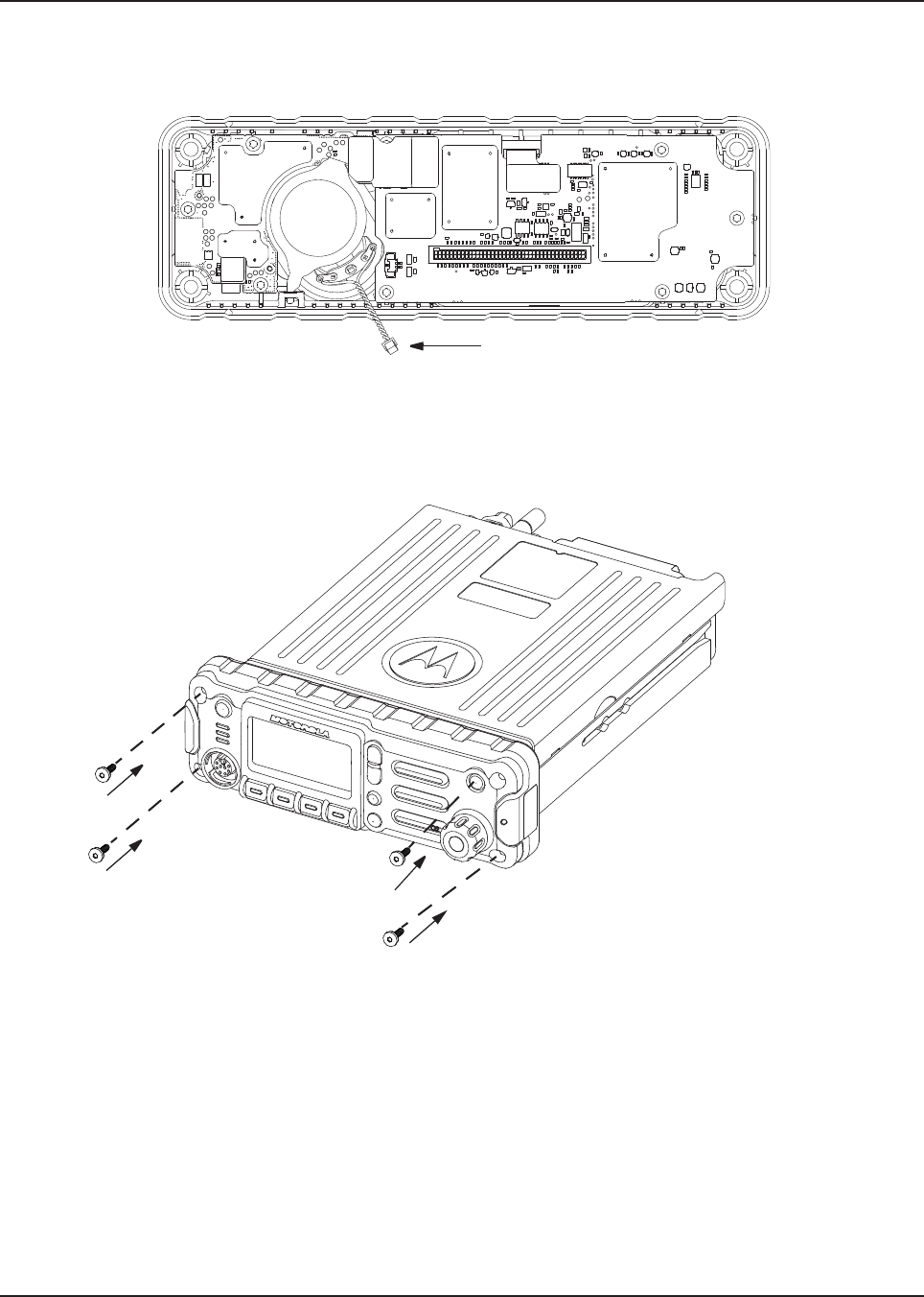
MN003109A01_aa
2-44 Standard Configurations Speaker
4. Put the control head face down on a clean, flat surface to avoid damaging it. Do not touch the
o-ring on the back housing.
5. Carefully disconnect the speaker connector from the circuit board as shown in Figure 2-52.
Figure 2-52. Disconnecting the Speaker Connector
6. Reattach the front housing assembly to the back housing assembly as shown in Figure 2-53.
Make sure that the flex is returned to its original position and that the o-ring on the back
housing assembly is not pinched.
Figure 2-53. Reattaching the Control Head
7. Secure the front housing assembly back to the back housing assembly with four new screws
using the Torx T-20 bit as shown in Figure 2-53. Apply 9 in. lbs. torque for each screw.
The followings are the procedure to disassemble your radio for high power radios:
1. Remove the O2 Control Head front housing assembly. Refer to the APX8500 HP Basic
Service Manual (Add APX8500 HP Basic Service ManualP/N).
2. Put the control head face down on a clean, flat surface to avoid damaging it. Do not touch the
o-ring on the back housing.
3. Carefully disconnect the speaker connector from the circuit board as shown in Figure 2-52.
Draft
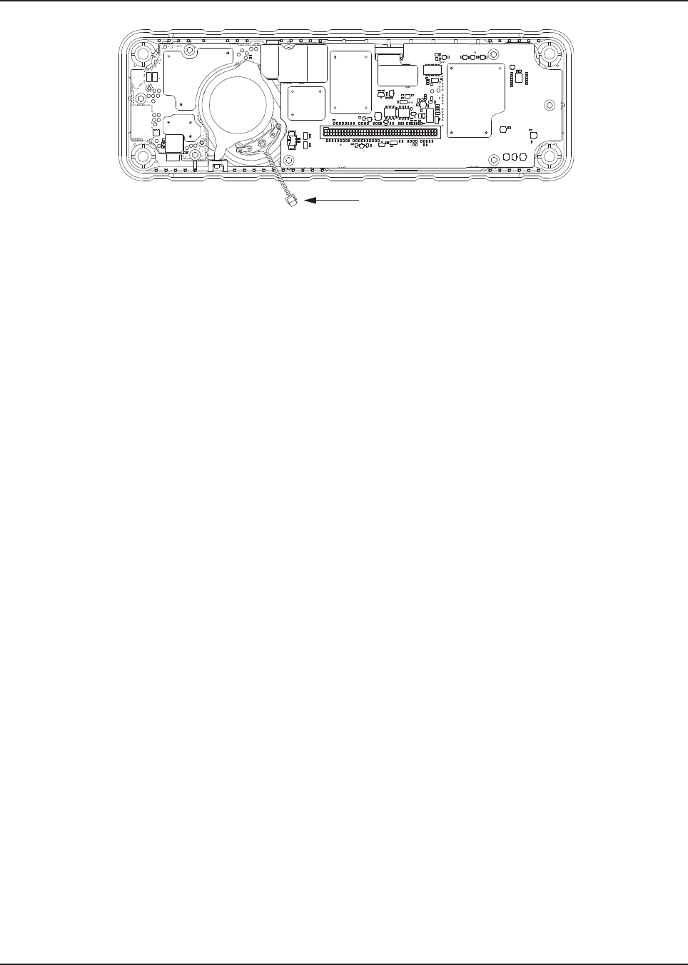
MN003109A01_aa
Standard Configurations Speaker 2-45
Figure 2-54. Disconnecting the Speaker Connector
4. Reattach the front housing assembly. Refer to the APX8500 HP Basic Service Manual,
Remove the O2 Control Head .
Draft
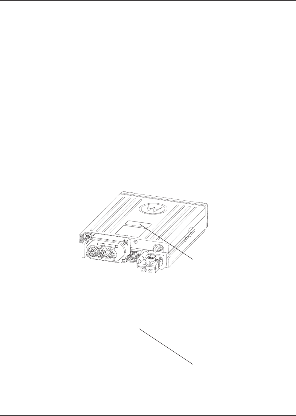
MN003109A01_aa
2-46 Standard Configurations Microphone Hang-Up Clip
2.6 Microphone Hang-Up Clip
2.6.1 Standard or O3 Control Head Hang-Up Clip
The hang-up clip must be within reach of the operator(s) and close enough to the control head to
prevent cable strain. Measure this distance before actually mounting the bracket. Since the bracket
has a positive-detent action, the microphone can be mounted in any position.
Use the hang-up clip as a template to locate the mounting holes. To avoid interference when
removing the microphone, install the flathead screw in the top clip hole.
Some microphone models require the grounding of the microphone clip in order for HUB operation to
work correctly. Refer to the documentation that comes with your Motorola Solutions microphone
model.
NOTE: For multi-control head configuration where only one of the control heads has a microphone,
the control heads without a microphone attached must have their HUB or Monitor pin
(J100-22) jumpered by a wire to GND (J100-1 or J100-14) for HUB operation to work.
2.7 RFID (Option)
An APX mobile radio equipped with an RFID tag allows an alternate option for tracking the radio
asset. Each RFID equipped radio has an RFID tag preprogrammed with the individual radio serial
number (also found on the FCC label) as well as band and radio model information (see below for
further information).
Figure 2-55. RFID Location on Mid Power Radio
Figure 2-56. RFID Location on High Power Radio
RFID Tag
RFID Tag
Draft
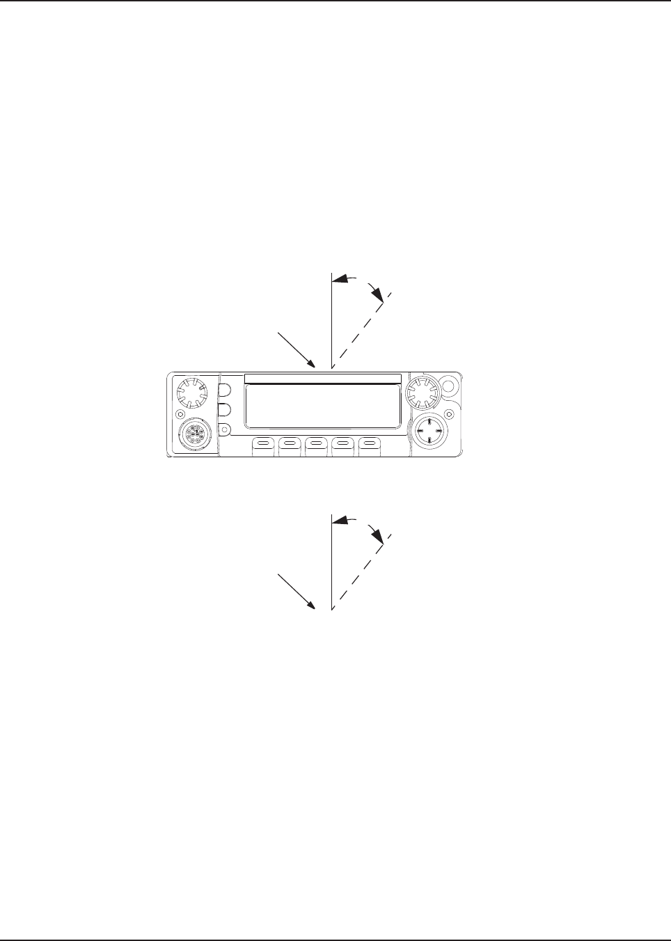
MN003109A01_aa
Standard Configurations RFID (Option) 2-47
2.7.1 RFID Reading
To read an RFID tag using a UHF Gen 2 RFID reader (e.g. Motorola Solutions MC9090-G), open an
appropriate RFID read application, point the RFID reader at the tag and activate the reader's RFID
antenna (e.g. pull Motorola Solutions MC9090-G scanning trigger). RFID reader must be within 1
foot from tag in order to read.
Two variables, Read Angle and Reader Orientation, aid in the distance needed to read and write to
the RFID Tag. Read distance is independent of Tag Angle, but the reader should be as close to
perpendicular to the tag as possible (Read Angle).
As Read Angle increases past 60 degrees, read distance begins to decrease; tag becomes
unreadable once Read Angle exceeds 90 degrees (see Figure 2-57). RFID tag cannot be read
through metal. The orientation of the reader (Reader Orientation) and the tag must be aligned to
improve read and writability (see Figure 2-61).
Figure 2-57. Read Angle for Mid Power Radio
Figure 2-58. Read Angle for High Power Radio
Read Angle
RFID Tag
Read Angle
RFID Tag
Draft
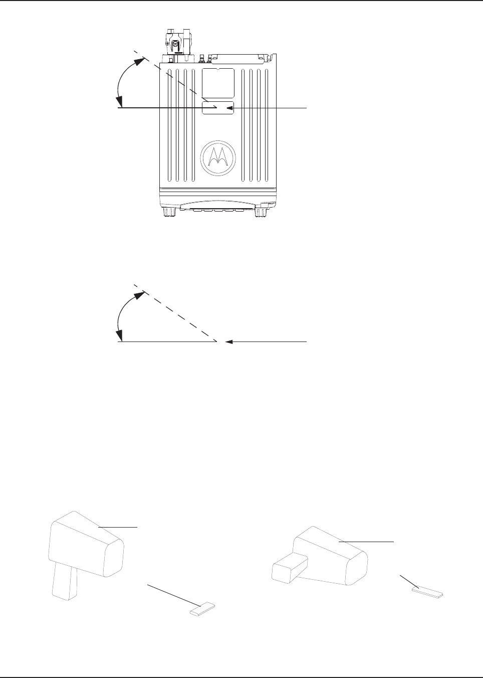
MN003109A01_aa
2-48 Standard Configurations RFID (Option)
.
Figure 2-59. Tag Angle for Mid Power Radio
.
Figure 2-60. Tag Angle for High Power Radio
Figure 2-61. Examples of Reader and Tag Aligned (Reader Orientation)
RFID Tag
Tag Angle
RFID Tag
Tag Angle
Reader
Tag
Reader
Tag
Draft

MN003109A01_aa
Standard Configurations RFID (Option) 2-49
Figure 2-62. Example of Reader and Tag Misaligned (Reader Orientation)
Reader
Tag
Draft

MN003109A01_aa
2-50 Standard Configurations RFID (Option)
2.7.2 Programming RFID (If Equipped)
The user can reprogram the tag (up to 12 ASCII characters when encoded to hexadecimal format)
using any UHF Gen 2 capable RFID writer (e.g. Motorola Solutions MC9090-G).
NOTE: Follow read direction in Section 2.7.1 to optimized reprogramming.
Table 2-1. Model Number Chart in 12-Digit ASCII Format
Model Number Radio Tier/Band/Output Level Last Two Digits
M37TXS9PW1AN APX Mobile 700/800 VHF UHF–HP
T0
M37TSS9PW1AN APX Mobile 700/800 VHF UHF–MP
M30KSS9PW1AN APX Mobile SB–MP VHF D2
M24KSS9PW1AN
APX Low Tier Mobile–MP VHF D8
M22KSS9PW1AN
M36KSS9PW1AN APX Lowest Tier Mobile–MP VHF D9
M30KTS9PW1AN APX Mobile SB–HP VHF D3
M30QSS9PW1AN APX Mobile SB–MP UHF1 E2
M30QTS9PW1AN APX Mobile SB–HP UHF1 E3
M30SSS9PW1AN APX Mobile SB–MP UHF2 D2
M20TSS9PW1AN APX Mobile DB–MP 700/800–MP VHF R2
M30TXS9PW1AN APX Mobile DB–MP 700/800–HP VHF R3
M30URS0PW1AN APX Mobile SB–MP 700/800 F2
M22URS9PW1AN
APX Low Tier Mobile–MP 700/800 F8
M24URS9PW1AN
M36URS9PW1AN APX Lowest Tier Mobile–MP 700/800 F9
M24QSS9PW1AN
APX Low Tier Mobile–MP UHF1 E8
M22QSS9PW1AN
M36QSS9PW1AN APX Lowest Tier Mobile–MP UHF1 E9
M24SSS9PW1AN
APX Low Tier Mobile–MP UHF2 E8
M22SSS9PW1AN
M36SSS9PW1AN APX Lowest Tier Mobile–MP UHF2 E9
M22WRS9PW1AN APX Low Tier Mobile–MP 900 F8
Table 2-2. Serial Number with Radio Band/Tier/Power
Characters Radio Band/Tier/Power
F 700/800 and 900
Draft

MN003109A01_aa
Standard Configurations Completing the Installation 2-51
2.8 Completing the Installation
Complete the installation by connecting the speaker to the accessory cable; verify the ignition sense
wire is attached according to planned ignition sense; verify the control head is attached to either the
TIB or the CAN extension cable; and then attach the power cable to the back of the transceiver.
DVHF
E UHF
R 700/800 and VHF
T Multi-Band
E UHF1 and UHF2
S 700/800 and UHF
0 APX 8500
1 APX 7000
2 APX 7500 Mid Power
3 APX 7500 High Power
4 APX 6000
5 APX 6500 Mid Power
6 APX 6500 High Power
7 APX Low Tier Portable
8 APX Low Tier Mobile MP/APX 4500 MP/APX 2500 MP
9 APX Lowest Tier Mobile MP/APX 1500 MP
Table 2-2. Serial Number with Radio Band/Tier/Power
Draft

MN003109A01_aa
2-52 Standard Configurations Completing the Installation
Draft
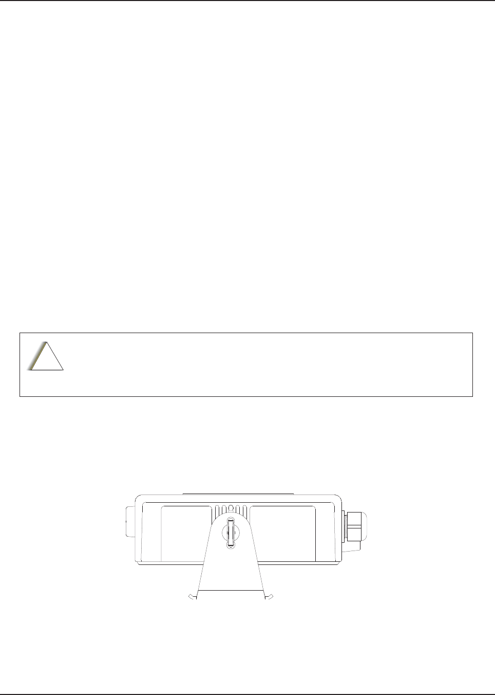
Chapter 3 Universal Relay Controller Installation
The Universal Relay Controller (URC) is an extension of and an orderable accessory for O7 or O9
control head. URC is used to control high power switching peripherals, e.g. lightbar. URC works on
all lightbars which can be controlled by power application. URC is connected to the transceiver's
MMP port.
The URC design consists of a microcontroller and uses 10 relays to control the switching device. A
separate ground for isolation exists between the relay and MCU sections, which is provided by the
use of iCoupler from Analog Devices. Each relay is connected to an output with 15 A fuse. The
maximum load allowed on each output is 12 A. Two cables, each with the maximum of 60 A, can be
used to connect to the input connector at the bus bar. Each cable is connected with a 60 A circuit
breaker. One-wire EEPROM is employed to enable MMP to recognize the URC accessory ID. CPS
can be used to program the relay patterns.
When installing URC, make sure to plan the installation carefully and leave additional room in the
front and rear of the box for cabling and accessory connections; and also to the sides of the radio so
that you may access and install the trunnion screws.
The recommended mounting location for URC is in the car trunk, either next to the transceiver or
within the area not further than 4.5 m away from the transceiver. Ensure that sufficient cooling is
provided. Do not cover URC with baggage, blankets, and others
3.1 Universal Relay Controller Mounting
The mounting location must be accessible and visible. Select a location that permits routing the
cable as directly as possible.
NOTE: For optimum URC performance, orient the mounting trunnion as shown in Figure 3-1.
Figure 3-1. Universal Relay Controller Orientation
An adjustable trunnion, which allows a number of mounting positions, is supplied for mounting the
URC. The installation must not interfere with the operation of the vehicle or its accessories.
Do not backfeed power into URC.
!
C a u t i o n
Draft
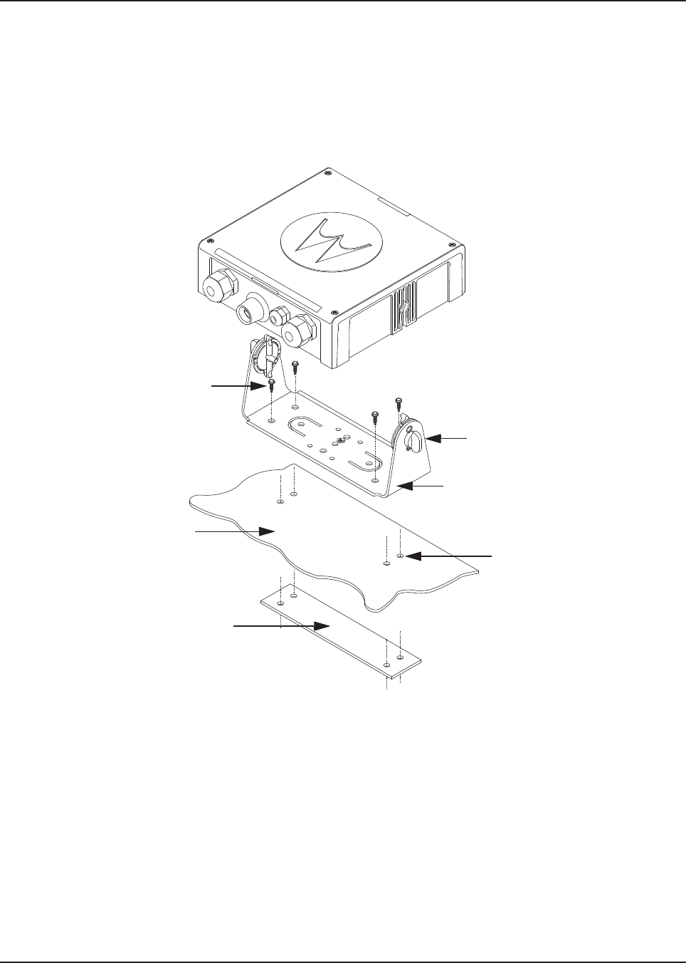
MN003109A01_aa
3-2 Universal Relay Controller Installation Universal Relay Controller Mounting
Install the URC as follows:
1. Use the URC trunnion as a template to mark the mounting holes;
drill 5/32" holes. If mounting on a plastic surface, use a metal backing plate.
2. Attach the trunnion bracket using all four 10 – 16" x 5/8" self-tapping screws provided.
3. Temporarily install the URC (adjust for proper viewing angle) and fasten it to the trunnion with
two wing screws. Test the installation to ensure that the unit is securely locked in place.
Figure 3-2. Universal Relay Controller Installation Exploded View
Adjust the universal relay controller
to desired angle and secure with
wing screws
Use four mounting screws on all
installations
TRUNNION
Drill four 5/32” holes in
mounting surface
Mounting surface
IMPORTANT:
Use a metal backing plate (not
supplied) if mounting trunnion on
plastic or unstable surface
Draft
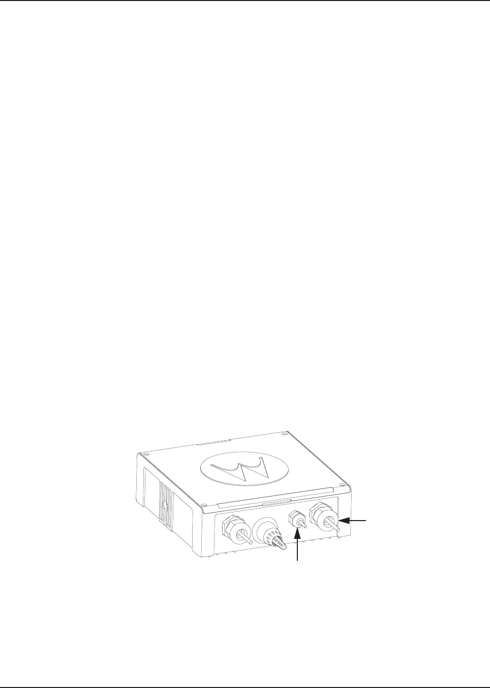
MN003109A01_aa
Universal Relay Controller Installation O7/O9 Universal Relay Controller Cable Assembly 3-3
3.2 O7/O9 Universal Relay Controller Cable Assembly
3.2.1 Power Cable
1. Remove the cap nut of power cable gland assembly, and insert the power cable through the
cap nut and neoprene seal in the cable gland body. Use power cable with either AWG 6 or
AWG 8 only (recommended OD range of cable is 5.5 mm to 9 mm) that is able to withstand
80 A and 50 A respectively, to ensure water sealing of the controller. User can decide to
install one or two power cables based on the requirements. The power cables (A+) are not
supplied.
2. The loose end of the power cable with cable strip length 7.94 mm (5/16”) is then placed on
the power lug and secured down by a set screw. The cap nut is then reassembled with
tightening torque 18 lb-in.
3. The other end of the power cable should be connected to circuit breaker (Motorola Solutions
part number 40012006001) end which indicates "AUX" and then, to power supply on the
other end which indicates "BAT", instead of connecting to power supply directly.
4. Repeat steps 1 to 3 to install the second power cable, if required.
5. If only one power cable is installed, it is recommended to cover the other side of the power
cable gland with power cable gland seal with tightening torque 18 lb-in.
3.2.2 Ground Cable
1. Remove the cap nut of ground cable gland assembly, insert the ground cable through the cap
nut and then reassemble the cap nut. Use ground cable with AWG 14 only (recommended
OD range of cable is 2 mm to 4 mm) that is able to withstand 5 A. The ground cables (A+) are
not supplied.
NOTE: The ground is used to switch the relays, and not act as a ground to the actual device being
controlled.
2. The loose end of the ground cable with cable strip length 7.94 mm (5/16”) is then connected
to a two-pin terminal block. Both pins on the terminal block are inter-connected and either pin
can be used. The cap nut is then reassembled with tightening torque 7 lb-in.
Figure 3-3. Power and Ground Cable Glands
Ground Cable Gland
Power Cable Gland
Draft
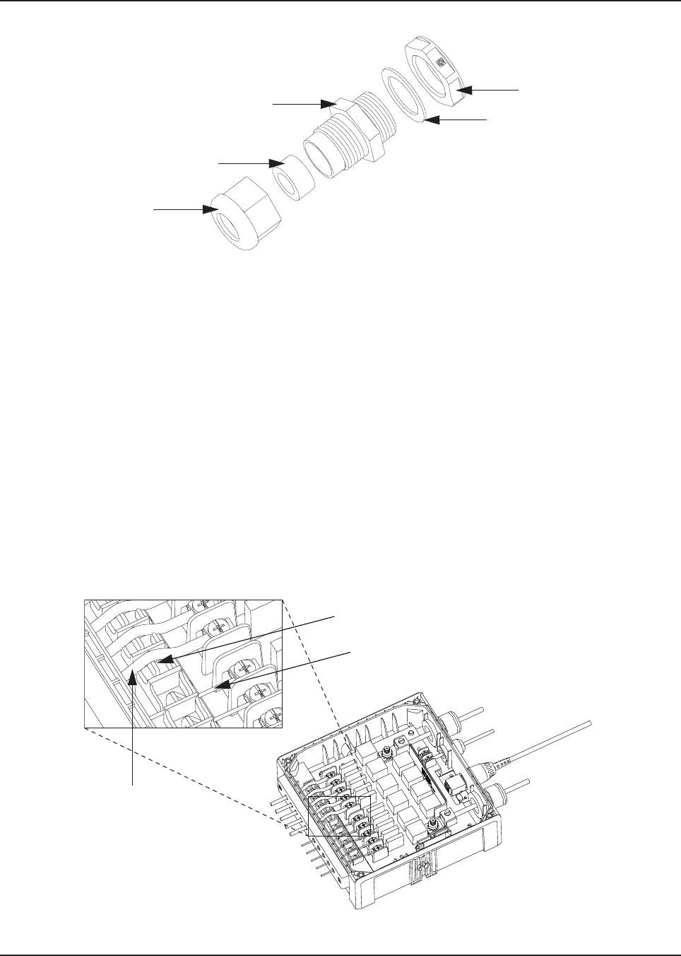
MN003109A01_aa
3-4 Universal Relay Controller Installation O7/O9 Universal Relay Controller Cable Assembly
Figure 3-4. Cable Gland Assembly with Gasket
3.2.3 Wires
1. Assemble the wires into the lightbar gasket retainer and lightbar gasket. The URC can
support lightbars through control wires with outer diameter ranging from
1.52 mm to 3.77 mm (0.06” to 0.148”), with wire gages ranging from AWG 12 – 20.
2. Each individual loose wire (prior to stripping off the wire jacket) needs to be inserted one at a
time through the chassis. Ensure the lightbar wire is straight before inserting the wire into the
chassis. Each wire is sealed individually by the radial gasket seal. When a thick wire that is
AWG 14 wire or wire OD > 2.90 mm is inserted through the chassis, there is potential torn at
the rubber gasket. Remove the rubber gasket residual and continue to the next step.
3. Thin wires 2.5 mm and below should be dressed into the retention feature using a black stick
(see Figure 3-5); thick wires above 2.5 mm should be routed above the retention feature.
Strip off the wire until 7.94 mm (5/16”) after the wire is inserted into the URC, and install the
wire into respective lightbar terminal block.
4. Cover the lightbar gasket retainer's hole with seal, gasket and ground cable gland, if no wire
is inserted.
Figure 3-5. Wires Installation
Counter Nut
Gasket, Cable Gland
Neoprene Seal
Cap Nut
Cable Gland
WIRE RETENTION FEATURE
LIGHTBAR WIRE WITH DIAMETER
2.5 mm AND BELOW
LIGHTBAR WIRE
WITH DIAMETER
ABOVE 2.5 mm
Draft
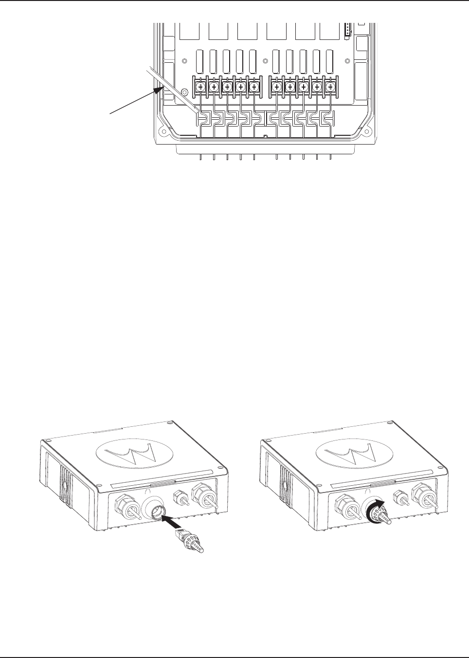
MN003109A01_aa
Universal Relay Controller Installation O7/O9 Universal Relay Controller Cable Assembly 3-5
Figure 3-6. Wire Installation with Black Stick
5. The lightbar gasket should be replaced at each reassembly of the wire.
NOTE: Use of other cable gages except as recommended in this manual may result in water
intrusion. Any reassembly of wire needs a new lightbar gasket replaced. If the current loading
for one wire is higher than 12 A, the wires should be splitted before being assembled to the
URC system. Wires kit (PMKN4109_) is provided to ease installation of the URC. Incorrect
use of the wires kit, e.g. improper connection at external loose end wires, may impact the
robustness of the URC.
Remove the wires and gasket residual inside the URC after the wire installation, before
closing the top housing of the URC.
3.2.4 O7/O9 to URC Cable
The O7/O9 to URC cable (Motorola Solutions part number 3064153H02) can be assembled either
before or after reassembling the top housing. Assemble the RJ45 port of the cable into the RJ45
connector on the URC and turn the locking collar instead of cable, 90 degrees to the right to ensure
it is locked properly. After that, test whether the cable is locked properly or not by trying to pull out the
cable.
Figure 3-7. O7/O9 to URC Cable Installation
Black Stick
Draft

MN003109A01_aa
Notes
3-6 Universal Relay Controller Installation
Draft
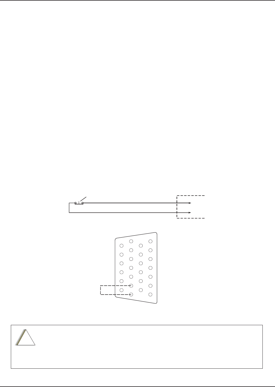
Chapter 4 Options and Accessories Installation
4.1 Dash-Mount Accessory Installation - Mid Power
For dash-mounted configurations, the accessories must be installed through the accessory
connector assembly that is located on the rear of the radio, adjacent to the power connector.
Motorola Solutions-approved accessories are supplied with male terminals crimped to a 20-gauge
wire specifically designed to fit the plug of the accessory connector assembly.
Insert the male terminal into the accessory connector assembly in the appropriate location and
connect the accessory connector assembly in the rear accessory port. Do not use other generic
terminals in the plug. Generic terminals can cause electrical intermittencies and may cause damage
to the plug.
4.1.1 Dash-Mount Emergency Pushbutton or Footswitch Installation
Mount the footswitch using the hardware that comes with the kit. Open the accessory cable
connector housing; remove the jumper wire. Connect the emergency switch wires to pins 14 and 15
(see Figure 4-1). Close the connector housing; route the finished cable from the switch location to
the control head location.
NOTE: The emergency footswitch should be attached with A+ unattached.
A+ should be attached after successfully securing the screws in the connector.
Figure 4-1. Emergency Switch Wiring Diagram
The radio is sold with correct accessory cables and jumpers in order to have emergency
de-activated by default, regardless of the setting in CPS. However, if cables are not used, or if
jumpers are removed without replacing with an emergency accessory button/switch at one of
the accessory ports, the radio power-up upon the application of A+. The display may not show
an indication that the radio is on, and this can result in an incorrect operation of the radio as well
as excessive current drain of the vehicle battery when the engine is off.
ACCESSORIES
CONNECTOR
J2 IN DASH MOUNT
J100 IN REMOTE MOUNT
PIN 14
PIN 15
NOTE 1
SPST NORMALLY CLOSED
EMERGENCY SWITCH
NOTE 1: REMOVE BLACK JUMPER WIRE INSIDE
ACCESSORY CONNECTOR HOUSING.
INSERT WIRES FROM EMERGENCY SWITCH
GND
EMER
1
7
8
14
13
20
21
26
!
C a u t i o n
Draft