Motorola Solutions 92FT7118 Mobile 2-Way Radio with WiFi User Manual APX TWO WAY RADIOS
Motorola Solutions, Inc. Mobile 2-Way Radio with WiFi APX TWO WAY RADIOS
Contents
Users Guide
Draft
Draft

Contents
Declaration of Conformity.........................8
Important Safety Information........10
Notice to Users (FCC and
Industry Canada)........................11
Software Version........................................... 11
Consignes de sécurité
importantes.................................12
Avis aux utilisateurs (FCC et
Industrie Canada).......................13
Version logicielle............................................13
Computer Software Copyrights....14
Documentation Copyrights...........15
Disclaimer.......................................16
Getting Started...............................17
How to Use This Guide..................................17
Notations Used in This Manual......................17
Additional Performance Enhancement.......... 17
ASTRO 25 Enhanced Data.................18
Dynamic System Resilience (DSR).... 18
CrossTalk Prevention..........................18
Encrypted Integrated Data (EID).........18
SecureNet...........................................18
P25 Digital Vehicular Repeater
System (DVRS)............................. 18
Conventional Talkgroup and Radio
Scan Enhancements......................18
What Your Dealer/System Administrator
Can Tell You.............................................19
Contents
1
English
Draft

Preparing Your Radio for Use.......20
Turning On the Radio.................................... 20
Adjusting the Volume.....................................21
Validating Compatibility During Power Up.....21
Identifying Radio Controls............22
Radio Parts and Controls.............................. 22
Control Head and Microphone............22
Programmable Features................................23
Assignable Radio Functions............... 23
Assignable Settings or Utility
Functions....................................... 26
Accessing the Preprogrammed Functions.....26
Menu Select Buttons...........................27
Advance Programmable Buttons........ 27
Home Button.......................................28
4-Way Navigation Button.................... 28
Data Feature Button........................... 28
Volume Knob...................................... 29
Using the Mode Knob......................... 29
Keypad.......................................................... 29
Keypad Characters – Uppercase
Mode..............................................29
Keypad Characters – Lowercase
Mode..............................................30
Keypad Characters – Numeric
Mode..............................................32
Keypad Characters – Hexadecimal
Mode..............................................33
Push-To-Talk (PTT) Button............................34
Identifying Status Indicators.........35
Status Icons...................................................35
Text Messaging Service (TMS) Indicators.....38
TMS Status Icons................................38
TMS Menu Options.............................39
LED Indicator.................................................40
Intelligent Lighting Indicators ........................ 41
Alert Tones.................................................... 43
General Radio Operation...............46
Selecting a Zone............................................46
Selecting a Radio Channel............................ 46
Selecting a Channel via Channel Search
Button....................................................... 47
Mode Select Feature..................................... 47
Contents
2
English
Draft

Saving a Zone and a Channel to a
Softkey...........................................48
Saving a Zone and a Channel to a
Button............................................ 48
Receiving and Responding to a Radio Call... 49
Receiving and Responding to a
Talkgroup Call................................49
Receiving and Responding to a
Private Call (Trunking Only)...........50
Receiving and Responding to a
Telephone Call (Trunking Only).....50
Methods to Make a Radio Call.......................51
Making a Talkgroup Call..................... 51
Making a Private Call (Trunking
Only).............................................. 52
Making a Telephone Call (Trunking
Only).............................................. 53
Switching Between Repeater or Direct
Operation Button...................................... 54
Monitor Feature............................................. 54
Monitoring a Channel..........................54
Monitoring Conventional Mode........... 55
Advanced Features........................56
Advanced Call Features................................ 56
Calling a Phone Not in the List............56
Selective Call (ASTRO
Conventional Only)........................ 56
Talkgroup Call Feature
(Conventional Operation Only)...... 57
Sending a Status Call......................... 58
Responding to the Dynamic
Regrouping Feature (Trunking
Only).............................................. 59
Dynamic Zone Programming (DZP)....60
Multiple Control Head Features.....................62
Setting the ID of the Initial Control
Head.............................................. 62
All Active Mode................................... 63
Activating and Deactivating
Intercom in All Active Mode........... 63
One Active Mode................................ 64
Contacts........................................................ 65
Making a Private Call from Contacts...66
Adding a New Contact Entry...............67
Deleting a Contact Entry.....................67
Adding a Contact to a Call List............68
Methods of Contact Editing in a
Call List.......................................... 68
Scan Lists...................................................... 70
Viewing a Scan List.............................70
Editing the Scan List........................... 70
Contents
3
English
Draft

Changing the Scan List Status............71
Viewing and Changing the Priority
Status.............................................72
Scan.............................................................. 72
Turning Scan On or Off.......................72
Turning Scan On While
Disregarding the Squelch Code
(Conventional Channels Only).......73
Transmitting While the Scan is On......73
Deleting a Nuisance Channel............. 73
Restoring a Nuisance Channel........... 74
Changing Priorities Status While
Scan is On..................................... 74
Restoring Priorities in a Scan List.......74
Using the Hang Up Box (HUB)........... 75
Call Alert Paging............................................75
Receiving a Call Alert Page................ 75
Sending a Call Alert Page...................76
Enabling and Disabling In-Call
User Alert.......................................77
Quick Call II (ASTRO P25 Digital
Trunking and Conventional)..................... 78
Initiating a Quick Call II
Transmission................................. 78
Emergency Operation....................................78
Sending an Emergency Alarm............ 79
Sending an Emergency Call
(Trunking Only).............................. 79
Sending an Emergency Alarm with
Emergency Call............................. 80
Sending a Silent Emergency Alarm.... 80
Special Considerations for
Emergencies..................................81
Automatic Registration Service (ARS)...........81
Selecting or Changing the ARS
Mode..............................................82
User Login Feature............................. 83
Text Messaging Service (TMS)..................... 85
Accessing the Messaging Features....85
Composing and Sending a New
Text Message................................ 86
Sending a Quick Text Message..........87
Priority Status and Request Reply
of a New Text Message................. 88
Secure Operations.........................................95
Enabling Secure Transmission........... 95
Accessing the Secure Feature............96
Managing Encryption.......................... 96
Global Positioning System / Global
Navigation Satellite System....................101
GPS Operation................................. 101
GPS Performance Enhancement......102
Contents
4
English
Draft

The Outdoor Location Feature
(Using GPS).................................102
Accessing the Outdoor Location
Feature........................................ 103
Turning Off GPS............................... 103
Saving a Waypoint............................104
Viewing a Saved Waypoint............... 105
Editing the Alias of a Waypoint......... 105
Editing the Coordinates of a
Waypoint......................................106
Deleting a Single Saved Waypoint....107
Deleting All Saved Waypoints...........108
Measuring the Distance and
Bearing from a Saved Waypoint.. 108
Location Feature in Emergency
Mode............................................109
Peer-Location on the Display
(ASTRO Conventional only)........ 109
Geofence (ASTRO 25 Trunking System).... 110
Entering the Geofence Area............. 111
Mission Critical Geofence................. 112
Entering Mission Critical Geofence...112
Exiting Mission Critical Geofence..... 112
Trunking System Controls........................... 113
Operating in Failsoft System.............113
Out-of-Range Radio..........................113
SmartZone........................................ 113
Site Trunking Feature....................... 114
Locking and Unlocking a Site............114
Site Display and Search Button........ 114
Trunked Announcement....................115
Ignition Switch Options................................ 116
Blank.................................................116
Tx Inhibit........................................... 116
PTT Tx Inhibit....................................116
Required........................................... 116
Soft Power Off.................................. 117
Ignition Only Power Up..................... 117
Using Emergency Power Up.............117
Auto Power Off Timer....................... 118
Voice Announcement.................................. 118
Site Selectable Alerts (ASTRO 25)..............119
Sending SSA Notification to Single
Site...............................................120
Sending SSA Notification to Single
Site Via Manual Entry.................. 121
Sending SSA Notification to All
Sites.............................................121
Sending SSA Notification to All
Available Sites............................. 122
Stopping SSA Notification of a
Single Site....................................123
Stopping SSA Notification of a
Single Site Via Manual Entry....... 123
Contents
5
English
Draft

Stopping SSA Notification of All
Sites.............................................124
Stopping SSA Notification of All
Available Sites............................. 125
Channel Change on Off Hook on All
Channels................................................ 125
Low Voltage Threshold Warning..................126
Wi-Fi............................................................ 127
Turning Wi-Fi On or Off.....................127
Checking the Wi-Fi Configuration
and Status of the Radio............... 128
Utilities......................................................... 129
Viewing Recent Calls........................129
Selecting the Power Level................ 129
Selecting a Radio Profile...................130
Controlling the Display Backlight...... 131
Turning the Keypad Tones On or
Off................................................131
Turning Voice Mute On or Off...........132
Using the Time-Out Timer.................132
Using Conventional Squelch
Operation Features......................132
Using the PL Defeat Feature............ 133
Digital PTT ID Support......................134
Smart PTT Feature (Conventional
Only)............................................ 134
Transmit Inhibit................................. 135
General Radio Information................136
External Alarms (Horn and Lights)....139
Helpful Tips.................................. 142
Radio Care.................................................. 142
Cleaning the External Surface of
the Radio..................................... 142
Cleaning the External Plastic
Surface........................................ 142
Accessories..................................144
Maritime Radio Use in the VHF
Frequency Range..................... 145
Special Channel Assignments.....................145
Emergency Channel......................... 145
Non-Commercial Call Channel......... 145
Operating Frequency Requirements............145
Declaration of Compliance for the Use of
Distress and Safety Frequencies............148
Technical Parameters for Interfacing
External Data Sources............................148
Contents
6
English
Draft

Glossary........................................149
Limited Warranty..........................155
MOTOROLA COMMUNICATION
PRODUCTS........................................... 155
I. WHAT THIS WARRANTY COVERS
AND FOR HOW LONG:......................... 155
II. GENERAL PROVISIONS:....................... 156
III. STATE LAW RIGHTS:............................157
IV. HOW TO GET WARRANTY SERVICE:.157
V. WHAT THIS WARRANTY DOES NOT
COVER:..................................................157
VI. PATENT AND SOFTWARE
PROVISIONS:........................................ 158
VII. GOVERNING LAW:.............................. 159
VIII. For Australia Only................................ 159
SERVICE.....................................................160
Contents
7
English
Draft

Declaration of Conformity
This declaration is applicable to your radio only if your radio is labeled with the FCC logo shown below.
Declaration of Conformity
Per FCC CFR 47 Part 2 Section 2.1077(a)
Responsible Party
Name: Motorola Solutions, Inc.
Address: 1303 East Algonquin Road, Schaumburg, IL 60196-1078, U.S.A.
Phone Number: 1-800-927-2744
Hereby declares that the product:
Model Name: APX Mobile
conforms to the following regulations:
FCC Part 15, subpart B, section 15.107(a), 15.107(d) and section 15.109(a)
Declaration of Conformity
8
English
Draft

Class B Digital Device
As a personal computer peripheral, this device complies with Part 15 of the FCC Rules. This device complies with
Industry Canada license-exempt RSS standard(s). Operation is subject to the following two conditions:
1This device may not cause harmful interference, and
2This device must accept any interference received, including interference that may cause undesired operation.
Note:
This equipment has been tested and found to comply with the limits for a Class B digital device, pursuant
to part 15 of the FCC Rules and Industry Canada license-exempt RSS standard. These limits are designed
to provide reasonable protection against harmful interference in a residential installation. This equipment
generates, uses and can radiate radio frequency energy and, if not installed and used in accordance with
the instructions, may cause harmful interference to radio communications. However, there is no guarantee
that interference will not occur in a particular installation.
If this equipment does cause harmful interference to radio or television reception, which can be determined
by turning the equipment off and on, the user is encouraged to try to correct the interference by one or
more of the following measures:
• Reorient or relocate the receiving antenna.
• Increase the separation between the equipment and receiver.
• Connect the equipment into an outlet on a circuit different from that to which the receiver is connected.
• Consult the dealer or an experienced radio or TV technician for help.
Declaration of Conformity
9
English
Draft

Important Safety Information
RF Energy Exposure and Product Safety Guide
for Mobile Two-Way Radios
ATTENTION!
This radio is restricted to Occupational use only.
Before using the radio, read the RF Energy Exposure
and Product Safety Guide for Mobile Two-Way
Radios which contains important operating
instructions for safe usage and RF energy awareness
and control for Compliance with applicable standards
and Regulations.
For a list of Motorola Solutions-approved antennas
and other accessories, visit the following website:
http://www.motorolasolutions.com/APX
Any modification to this device, not expressly
authorized by Motorola Solutions, may void the user’s
authority to operate this device.
Under Industry Canada regulations, this radio
transmitter may only operate using an antenna of a
type and maximum (or lesser) gain approved for the
transmitter by Industry Canada. To reduce potential
radio interference to other users, the antenna type
and its gain should be so chosen that the equivalent
isotropically radiated power (e.i.r.p.) is not more than
that necessary for successful communication.
This radio transmitter has been approved by Industry
Canada to operate with Motorola Solutions-approved
antenna with the maximum permissible gain and
required antenna impedance for each antenna type
indicated. Antenna types not included in this list,
having a gain greater than the maximum gain
indicated for that type, are strictly prohibited for use
with this device.
Note:
Setting up the radio as an RF Modem takes
complete control of the radio. In this mode, the
radio no longer responds to button and PTT
presses nor will it unmute to voice activity.
This mode is designed to receive and pass
specifically formatted over the air data to a
tethered computer with RF modem enabled
applications. This mode can only be exit by
reprogramming the radio with Customer
Programming Software (CPS) to not operate
in RF modem mode and cycling power.
Important Safety Information
10
English
Draft

Notice to Users (FCC and Industry
Canada)
This device complies with Part 15 of the FCC rules
and Industry Canada's license-exempt RSS's per the
following conditions:
• This device may not cause harmful interference.
• This device must accept any interference
received, including interference that may cause
undesired operation.
• Changes or modifications made to this device, not
expressly approved by Motorola, could void the
authority of the user to operate this equipment.
Software Version
All the features described in the following sections are
supported by the software version R15.00.00 or later.
See Accessing the Radio Information on page 137 to
determine the software version of your radio.
Check with your dealer or system administrator for
more details of all the features supported.
Notice to Users (FCC and Industry Canada)
11
English
Draft

Consignes de sécurité importantes
Radios bidirectionnelles mobiles : exposition aux
radiofréquences et sécurité du produit
ATTENTION!
Cette radio ne doit être utilisée qu'à des fins
professionnelles. Avant d'utiliser la radio, lisez le
guide Radios bidirectionnelles mobiles : exposition
aux radiofréquences et sécurité du produit, qui
contient d'importantes instructions de fonctionnement
pour une utilisation sécuritaire et des informations sur
l'exposition aux fréquences radioélectriques, dans le
but d’assurer votre conformité aux normes et
règlements en vigueur.
Visitez le site Web suivant pour obtenir la liste des
antennes et des autres accessoires approuvés par
Motorola :
http://www.motorolasolutions.com/APX
Selon la réglementation d'Industrie Canada, cet
émetteur radio ne peut être utilisé qu'avec une
antenne dont le type et le gain maximal (ou minimal)
sont approuvés par Industrie Canada pour cet
émetteur. Afin de limiter les interférences radio pour
les autres utilisateurs, le type et le gain de l'antenne
doivent être choisis de façon à ce que la puissance
isotrope rayonnée équivalente (P.I.R.E.) ne soit pas
plus forte qu'il ne le faut pour établir la
communication.
Cet émetteur radio a été approuvé par Industrie
Canada pour utilisation avec une antenne approuvée
par Motorola offrant le gain maximal autorisé et
l'impédance requise pour le type d'antenne indiqué. Il
est strictement interdit d'utiliser avec cet appareil tout
type d'antenne ne figurant pas dans cette liste et
présentant un gain supérieur au maximum indiqué
pour le type.
Consignes de sécurité importantes
12
Français
(Canada)
Draft

Avis aux utilisateurs (FCC et Industrie
Canada)
Cet appareil est conforme à la partie 15 des règles de
la FCC et d'Industrie Canada permis exemptés RSS
de par la conditions suivantes:
• Ce dispositif ne doit pas causer d'interférences
nuisibles.
• Cet appareil doit accepter toute interférence
reçue, y compris les interférences qui peuvent
perturber le fonctionnement.
• Les changements ou les modifications apportées
à ce dispositif, non expressément approuvées par
Motorola, peuvent annuler le droit de l'utilisateur à
utiliser cet équipement.
Version logicielle
Toutes les fonctions décrites dans les sections
suivantes sont prises en charge par la version
R15.00.00 ou les versions ultérieures du logiciel de la
radio.
Pour obtenir davantage de renseignements à propos
des fonctions prises en charge, adressez-vous à
votre détaillant ou à votre administrateur de système.
Avis aux utilisateurs (FCC et Industrie Canada)
13
Français
(Canada)
Draft

Computer Software Copyrights
The Motorola products described in this manual may
include copyrighted Motorola computer programs
stored in semiconductor memories or other media.
Laws in the United States and other countries
preserve for Motorola certain exclusive rights for
copyrighted computer programs including, but not
limited to, the exclusive right to copy or reproduce in
any form the copyrighted computer program.
Accordingly, any copyrighted Motorola computer
programs contained in the Motorola products
described in this manual may not be copied,
reproduced, modified, reverse-engineered, or
distributed in any manner without the express written
permission of Motorola. Furthermore, the purchase of
Motorola products shall not be deemed to grant either
directly or by implication, estoppel, or otherwise, any
license under the copyrights, patents or patent
applications of Motorola, except for the normal non-
exclusive license to use that arises by operation of
law in the sale of a product.
Computer Software Copyrights
14
English
Draft

Documentation Copyrights
No duplication or distribution of this document or any
portion thereof shall take place without the express
written permission of Motorola. No part of this manual
may be reproduced, distributed, or transmitted in any
form or by any means, electronic or mechanical, for
any purpose without the express written permission of
Motorola.
Documentation Copyrights
15
English
Draft

Disclaimer
The information in this document is carefully
examined, and is believed to be entirely reliable.
However, no responsibility is assumed for
inaccuracies. Furthermore, Motorola reserves the
right to make changes to any products herein to
improve readability, function, or design. Motorola
does not assume any liability arising out of the
applications or use of any product or circuit described
herein; nor does it cover any license under its patent
rights, nor the rights of others.
Disclaimer
16
English
Draft
Getting Started
How to Use This Guide
This User Guide covers the basic operation of the
APX Mobiles.
However, your dealer or system administrator may
have customized your radio for your specific needs.
Check with your dealer or system administrator for
more information.
Notations Used in This Manual
Throughout the text in this publication, you will notice
the use of Warning, Caution, and Note. These
notations are used to emphasize that safety hazards
exist, and the care that must be taken or observed.
Warning:
An operational procedure, practice, or
condition and so on, which may result in injury
or death if not carefully observed.
Caution:
An operational procedure, practice, or
condition and so on, which may result in
damage to the equipment if not carefully
observed.
Note:
An operational procedure, practice, or
condition and so on, which is essential to
emphasize.
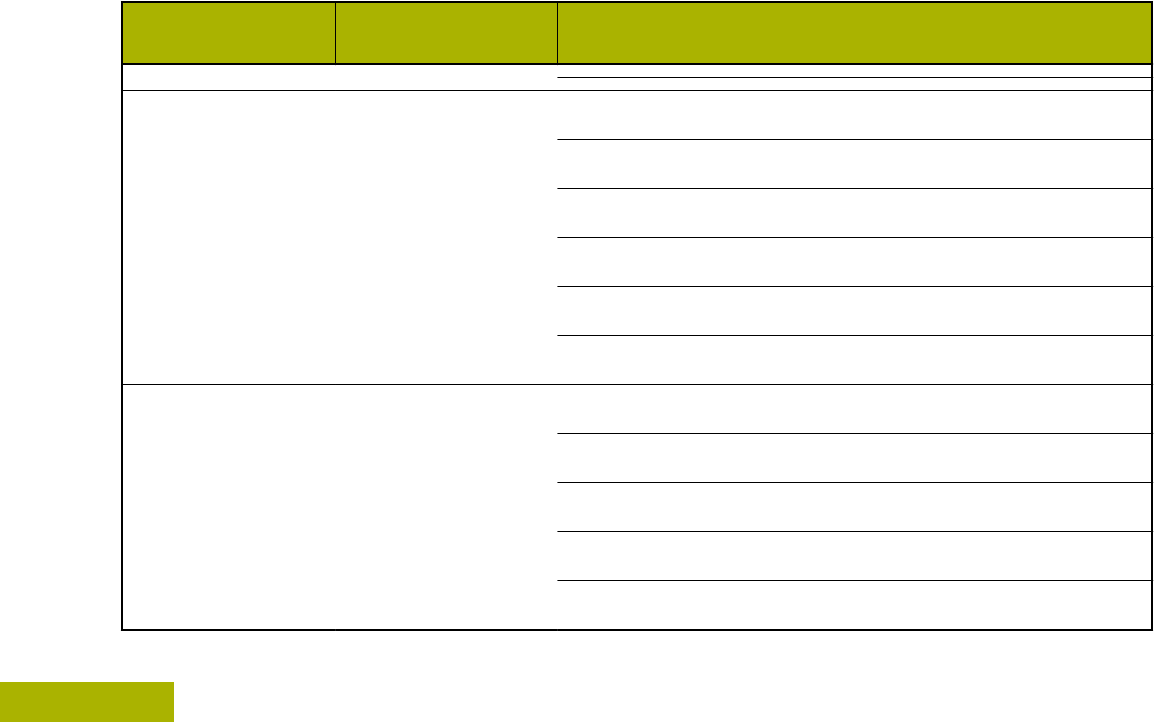
The following special notations identify certain items.
Example Description
Home button
or
Buttons and keys are shown in
bold print or as an icon.
PHONE Menu entries are shown similar to
the way they appear on the display
of the radio.
This means “Press the right side of
the 4-Way Navigation Button”.
Additional Performance Enhancement
The following performance enhancements are some
of the latest creations designed to enhance the
security, quality and efficiency of the radios.
Getting Started
17
English
Draft

ASTRO 25 Enhanced Data
ASTRO 25 Enhanced Data is optimized to handle
different message sizes and variable update rates
from different applications of the radio. Add Enhanced
Data to the Integrated Data system with a software
installation to improve data channel efficiency and
enable denser network traffic.
Dynamic System Resilience (DSR)
DSR ensures the radio system is seamlessly
switched to a backup master site dynamically in case
of system failure. DSR also provides additional
indication e.g. failure detection, fault recovery, and
redundancy within the system to address to the user
in need. Mechanisms related to the Integrated Voice
and Data (IV&D) or data centric are all supported by
DSR.
CrossTalk Prevention
This feature prevents crosstalk scenarios from
happening, especially when a wideband antenna is
used. This feature allows the adjustment of the
internal SSI clock rate of the radio. This subsequently
reduces the possibility of radio frequency interfering
spurs and prevents the issues of crosstalk.
Encrypted Integrated Data (EID)
EID provides security encryption and authentication of
IV&D data bearer service communication between the
radio and the Customer Enterprise Network.
SecureNet
SecureNet allows user to perform secured
communications on an Analog or Motorola Data
Communication (MDC) channel. The MDC Over-the-
Air Rekeying (OTAR) feature will allow users to
perform OTAR activities on an MDC channel.
P25 Digital Vehicular Repeater System (DVRS)
Motorola Solutions offers an MSI Certified APX
compatible, 3rd Party, P25 Digital Vehicular Repeater
System (DVRS) that provides low cost portable radio
coverage in areas where only mobile radio coverage
is available and portable radio coverage is either
intermittent or non-existent.
Conventional Talkgroup and Radio Scan
Enhancements
A few enhancements have been made to the
Conventional Talkgroup at the system. These
enhancements improve the Scan feature operation
significantly when multiple agencies are using a
Getting Started
18
English
Draft

single conventional radio frequency channel. These
enhancements allow users to use Selective Squelch
to operate on only the subset of talkgroups that are
relevant to the users rather than all talkgroups on the
channel. These Scan improvements have been made
to eliminate the audio holes that were present and to
turn on the busy LED when activity is present on the
channel. Mixed Vote Scan and Standard
Conventional Scan configurations are supported.
Priority Operation is also supported.
Up to 30 different talkgroups can be supported using
conventional channels. A maximum of four talkgroups
can be supported when Vote Scan channels are
being used.
Smart PTT is supported with this enhancement as
Smart PTT prevents users from transmitting while
other users are on the channel.
Note:
User Selectable Talkgroups are not
compatible with this Conventional Talkgroup
Enhancement.
What Your Dealer/System Administrator Can
Tell You
Check with your dealer or system administrator, if the
radio is to be operated in extremely cold temperatures
(less than -30 °C or more than +60 °C), for the correct
radio settings to ensure proper operation.
You can consult your dealer or system administrator
about the following:
• Is your radio programmed with any preset
conventional channels?
• Which buttons have been programmed to access
other features?
• What optional accessories may suit your needs?
Note:
Specifications may vary for different radio
models. Check with your dealer or system
administrator for more information.
Getting Started
19
English
Draft
Preparing Your Radio for Use
This section provides simple instructions to prepare
your radio for use.
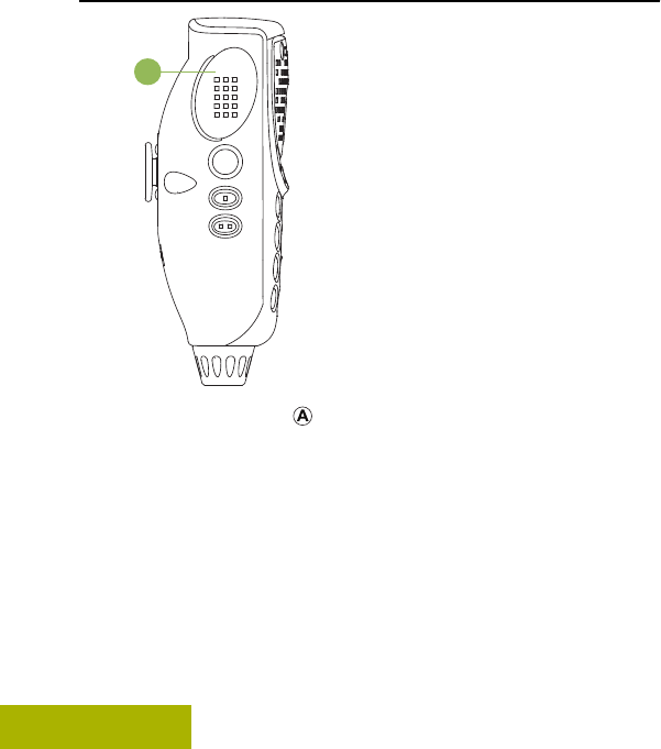
Turning On the Radio
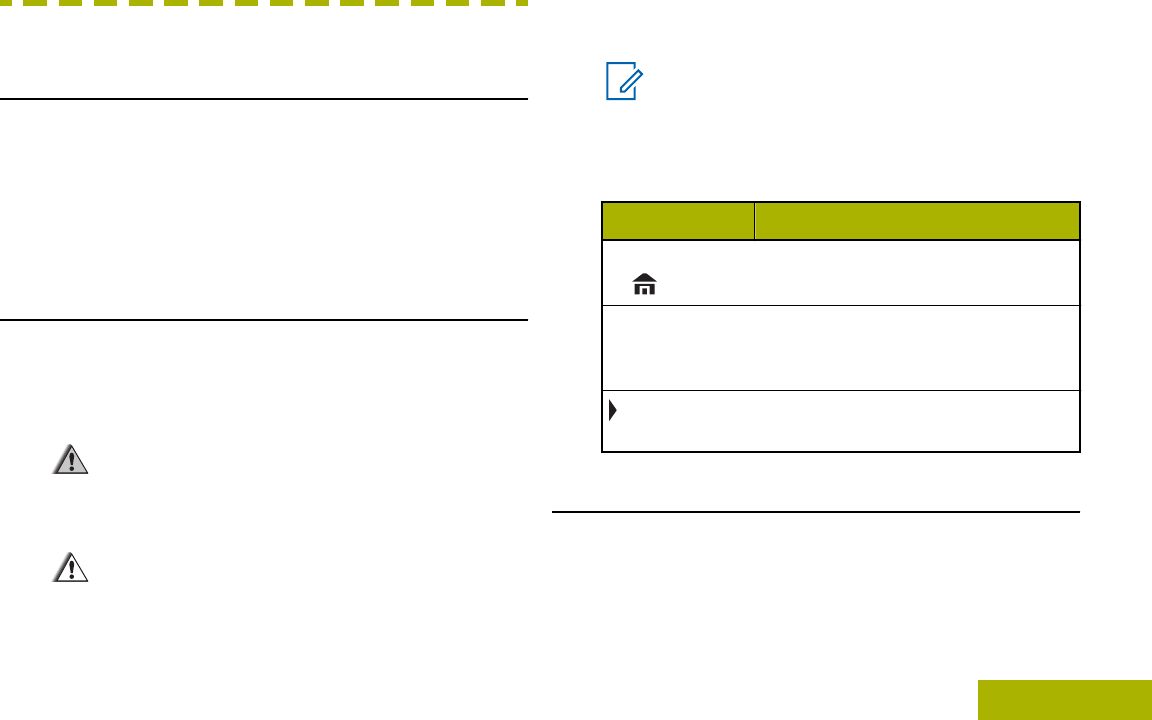
1Press the Power On/Off Button briefly to
power on the radio.
A
After a short time, the red, yellow and green LEDs
light up. The display then shows Zone and
channel text, and menu items display on the
screen.
The backlight turns on to the last selected dim
level.
Note:
Pressing the Power On/Off Button before
the LED lights up will be ignored.
If FAIL ##/## appears in the display, the
radio will not function until the condition
has been corrected.
If ERROR ##/## appears, some non-critical
data has been changed. If either of these
displays appear, if the display goes blank,
or if the unit appears to be locked up, see
Helpful Tips on page 142 for more
information.
If CH MISMATCH appears, means that either
the Control Head has been connected to
an incompatible transceiver, or vice versa.
If your radio does not power up, contact
your dealer.
2To turn off the radio, press the Power On/Off
Button after the LEDs light up.
Note:
The duration that user must press and hold
the Power On/Off Button to turn off the
Preparing Your Radio for Use
20
English
Draft
radio is programmable by a qualified radio
technician.
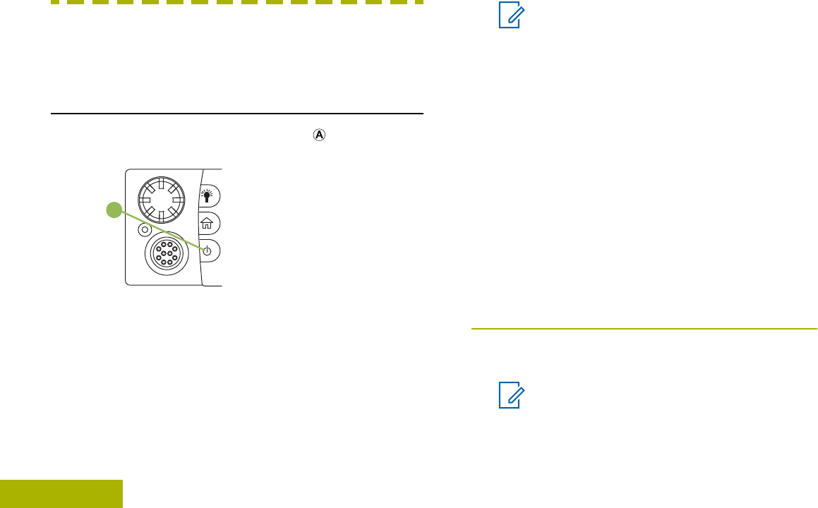
Adjusting the Volume
1To increase the volume, rotate the Volume Knob
clockwise.
A
2To decrease the volume, rotate this knob
counterclockwise.
Validating Compatibility During Power Up
The radio validates and updates the software and
hardware of your control head(s) during power up.
During validation, the display shows MAINTENANCE
MODE REMOTE DEVICE; promptly followed by other
maintenance statuses.
Press the Power On/Off Button to reset when the
display shows UPDATE DONE PLEASE RESET upon
completion, or when the display shows UPDATE
FAILED PLEASE RESET when it fails to update.
If the software updates are complete, the radio runs
the usual power up operation.
If the updates are incomplete, the radio runs the
Maintenance Mode and the display shows
MAINTENANCE MODE REMOTE DEVICE; promptly
followed by other maintenance statuses again.
Note:
If SW INCOMPLETE appears, use Flashport
Recovery Tool to update the control heads
before you power on the radio again.
Preparing Your Radio for Use
21
English
Draft
Identifying Radio Controls
Radio Parts and Controls
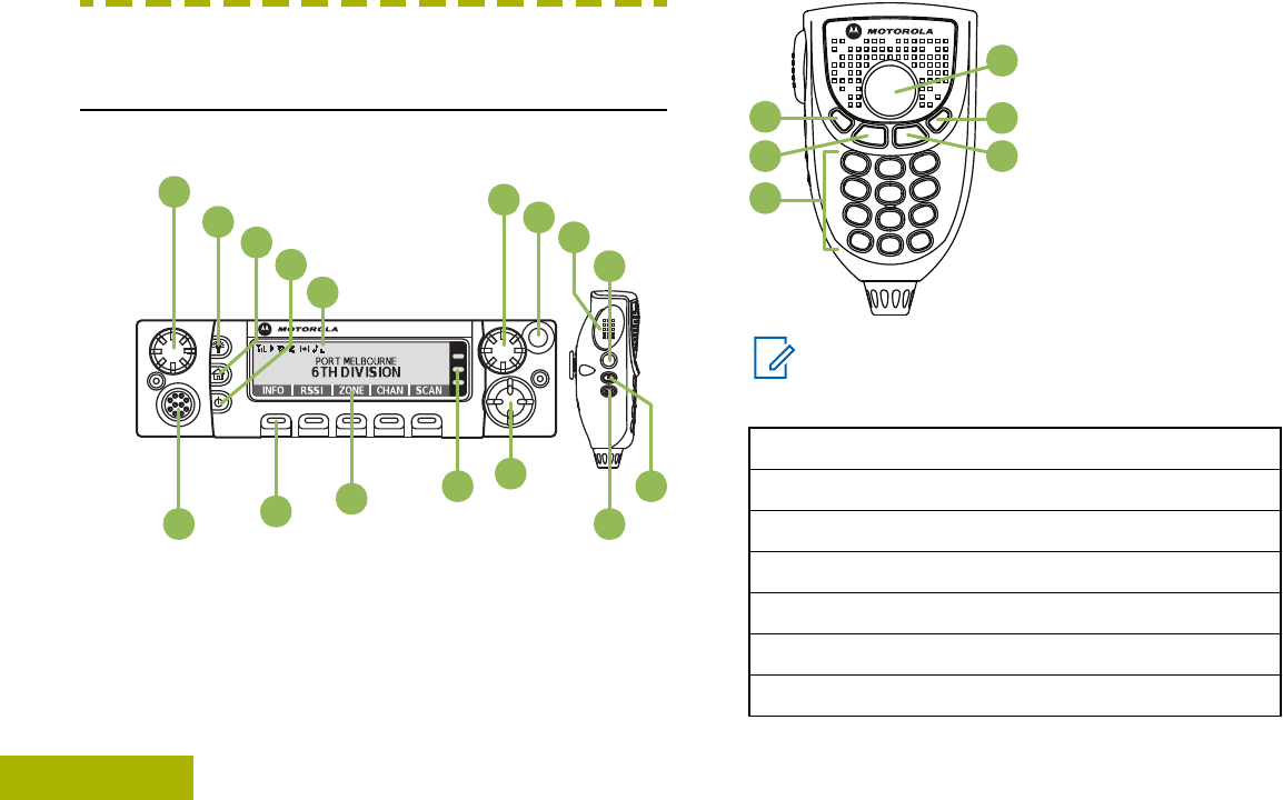
Control Head and Microphone
1 6
8
10
12
13
14
15
16 11
9
7
2345
17
18 20
21
22
19
Note:
The microphone is not part of a radio. It is an
optional accessory.
1 Accessory Port (Microphone)
2 Menu Select Button[1]
3 Menu Entries
4 LED Indicators
5 Navigation Button
6 Accy 2-Dot Button[1]
7 Accy 1-Dot Button[1]
Identifying Radio Controls
22
English
Draft

8 Accy No-Dot Button (Purple)[1]
9 Push-to-Talk (PTT) Button
10 Orange Button[1]
11 Mode Knob
12 Indicators
13 Power On/Off Button
14 Home Button
15 Dim Button
16 Volume Knob
17 Data Feature Button[1]
18 Home Button (Microphone)
19 Keypad Buttons
20 Okay/Select Button ( )
21 Cancel Button (X)
22 Navigation Button (Microphone)
Programmable Features
Any reference in this manual to controls that are
preprogrammed means that a qualified radio
technician must use the radio programming software
to assign a feature to a control.
Your dealer can program the programmable buttons
as shortcuts to radio functions or preset channels/
groups depending on the duration of a button press:
Press Pressing and releasing rapidly.
Long press Pressing and holding for the
preprogrammed duration (between
0.25 seconds and 3.75 seconds).
Hold down Keeping the button pressed.
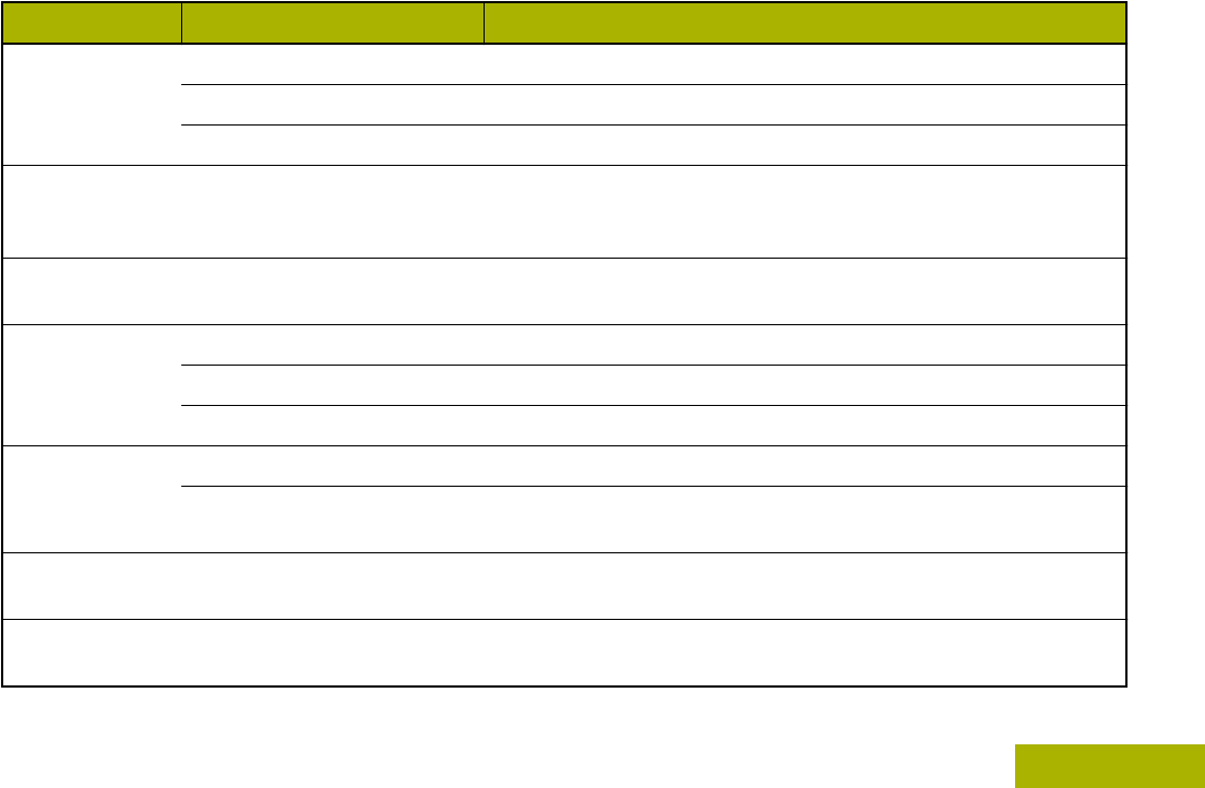
Assignable Radio Functions
Call Alert Allows the radio to function like
a pager, or to verify if a radio is
active on the system.
1These radio controls/buttons are programmable.
Identifying Radio Controls
23
English
Draft

Call Response Allows you to answer a private
call or phone call.
Channel Selects a channel.
Contacts Selects the Contacts menu.
Dynamic ID
(Conventional
Only)
Allows you to edit the ASTRO
Individual ID and/or MDC
Primary ID of the radio.
Dynamic Priority
(Conventional
Only)
Allows any channel in a Scan
List (except for the Priority-One
channel) to temporarily replace
the Priority-Two channel.
Emergency Depending on the
programming, initiates or
cancels an emergency alarm or
call.
Information Displays the information of the
radio.
Intercom Enables users of multiple
control heads to talk to each
other via the control heads in a
multi-control head setup.
Internet Protocol
Address Display the Internet Protocol
(IP) address, device name and
status of the radio.
Location Determines the current location
(latitude, longitude, time and
date), and also the distance
and bearing to another location.
Or, turns the GPS functionality
on or off for all locations.
Message Enters the current message list.
Monitor
(Conventional
Only)
Monitors a selected channel for
all radio traffic until function is
disabled.
Multiple Private
Line
(Conventional
Only)
Selects the Multiple Private
Line lists.
Nuisance Delete Temporarily removes an
unwanted channel, except for
priority channels or the
designated transmit channel
from the scan list.
Identifying Radio Controls
24
English
Draft

Launches a specific feature
with one single button-press.
You can setup as many as four
separately programmed
buttons for four different
features.
Phone Allows you to make and receive
calls similar to standard phone
calls.
Private Call
(Trunking Only) Allows a call from an individual
radio to another individual
radio.
Radio Profiles Allows easy access to a set of
preprogrammed visual and
audio settings of the radio.
Recent Calls Allows easy access to the list of
calls recently received or made.
Rekey Request Notifies the dispatcher you
want a new encryption key.
Repeater Access
Button (RAB)
(Conventional
Only)
Allows user to manually send a
repeater access codeword.
Reprogram
Request
(Trunking Only)
Notifies the dispatcher you
want a new dynamic
regrouping assignment.
Request-To-Talk
(Conventional
Only)
Notifies the dispatcher you
want to send a voice call.
Scan Toggles scan on or off.
Scan List
Programming Selects the scan list for editing
(by long press on the Scan
button).
Secure/Clear Toggles secure transmission
on or off.
Selective Call
(Conventional
Only)
Calls an assigned radio.
Siren Turns different Siren Tones on
or off.
Site Display/
Search (Trunking
Only)
Displays the current site ID and
RSSI value; performs site
search for Automatic Multiple
Site Select (AMSS) or
SmartZone operation.
Identifying Radio Controls
25
English
Draft

Site Lock/Unlock
(Trunking Only) Locks onto a specific site.
Status (Astro 25
Trunking Only) Sends data calls to the
dispatcher about a predefined
status.
Talkaround/Direct
(Conventional
Only)
Toggles between using a
repeater and communicating
directly with another radio.
Talkgroup
(Conventional
Only)
Allows a call from an individual
radio to a group of radios.
Text Messaging
Service (TMS) Selects the text messaging
menu.
TMS Quick Text Selects a predefined message.
User Automatically registers with the
server.
Zone Down Toggles downward through the
zones in the radio.
Zone Select Allows selection from a list of
zones.
Zone Up Toggles upward through the
zones in the radio.
Assignable Settings or Utility Functions
Dim Changes the display
brightness.
Front/Rear Switches one of two control
heads to be active at one
time.
Horns/Lights Toggles horns and lights
feature on or off.
Keypad Lock Toggles the keypad lock on
or off.
Low Power Toggles transmit power level
between high and low.
Voice
Announcement Audibly indicates the current
feature mode, Zone or
Channel the user has just
assigned.
Voice Mute Toggles voice mute on or off.
Accessing the Preprogrammed Functions
You can access various radio functions through one
of the following methods.
Identifying Radio Controls
26
English
Draft
•A short or long press of the relevant
programmable buttons.
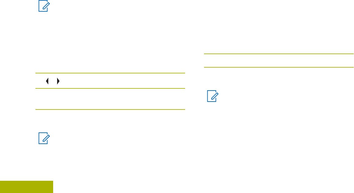
•Use the Menu Select Button ( ).
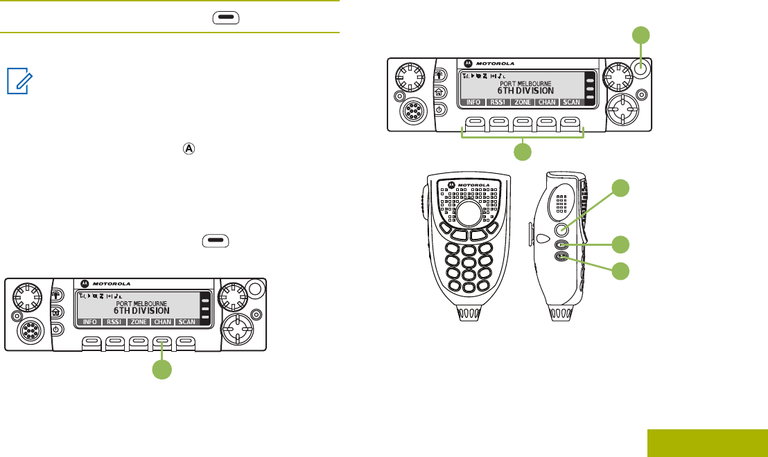
Menu Select Buttons
Note:
Check with your dealer or system
administrator for the list of features activated
in your radio.
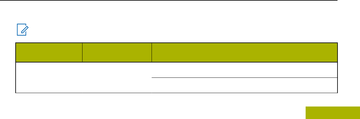
Use the Menu Select button to access the menu
entry of your radio feature. Your radio may be
preprogrammed differently from the following
example, but the steps for selecting a channel may
appear as shown below:
Press the Menu Select button ( ) directly below
CHAN.
A
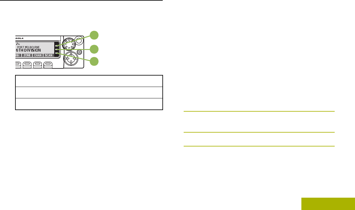
Advance Programmable Buttons
This feature is to help you to shorten the process of
applying certain common features.
C
B
A
D
E
AOrange Button[2]
BMenu Select Buttons[2]
Identifying Radio Controls
27
English
Draft
CAccy No-Dot Button (Purple)[2]
DAccy 1-Dot Button[2]
EAccy 2-Dot Button[2]
(Quick
Access)
One Touch
Button
Enters a menu with a short press on
the preprogrammed One Touch
button. Features assigned to these
buttons are Call, Call Alert, Phone,
Repeater Access, MDC RTT Button
Access, Status and Message.
Home Button
Pressing the button returns you to the Home
(default) screen. In most cases, this is the current
mode. For selected radio features, the button is
also used to save user-edited radio settings or
information before returning you to the Home screen.
Note:
Some features do not require you to press
to go to the Home screen. Refer to the
individual feature sections in this manual for
further details on saving user-edited radio
settings or information.
The button also can revert to home channel from
any other zone and mode in the radio. Check with
your dealer or system administrator for more
information.
4-Way Navigation Button
Use the 4-Way Navigation Button to scroll up, down,
left or right with one of the following methods.
• Press and release one of the button to scroll from
one entry to the next one.
• Press and hold one of the button to have the radio
toggles through the list automatically (release the
button to stop).
Data Feature Button
Use Data Feature button to access data-related
features, such as the Text Messaging Service (TMS)
feature screen.
2These programmable buttons support the One Touch Button feature.
Identifying Radio Controls
28
English
Draft
Volume Knob
Use this Volume Knob to adjust the volume of the
speakers by turning it clockwise or counterclockwise.
Using the Mode Knob
Use this Mode Knob to scroll through the
channels by turning it clockwise or
counterclockwise.
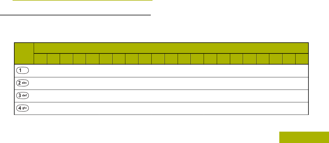
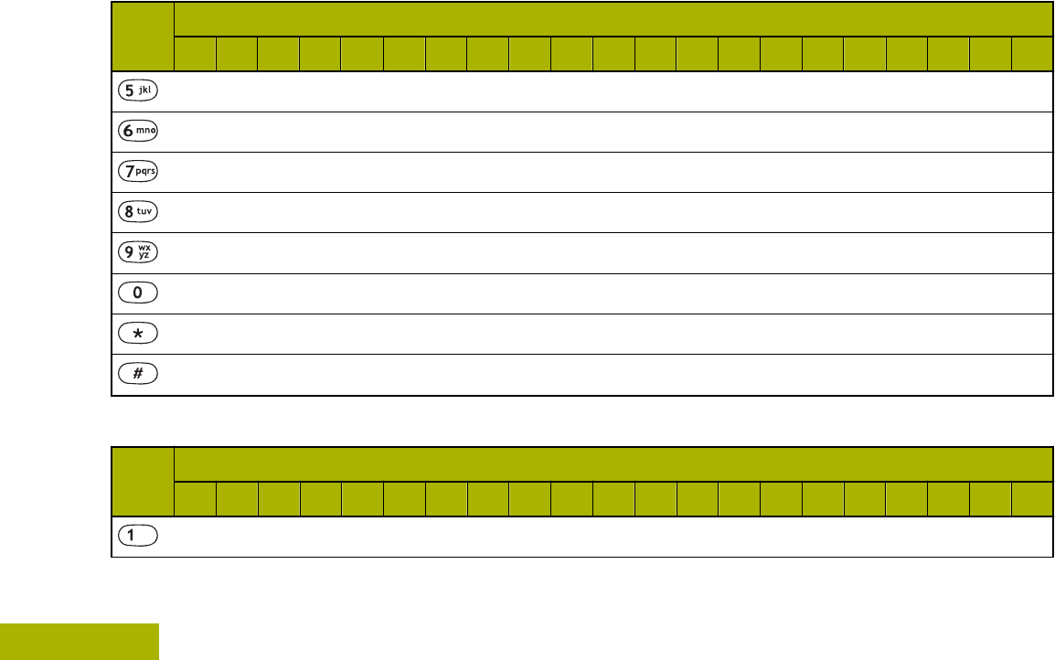
Keypad
You can use the 3 x 4 alphanumeric keypad on the
keypad microphone to access your radio’s features.
The keypad functions in a manner similar to a
standard telephone keypad when entering numeric
digits. When the keypad is used to edit a list, each
key can generate different characters of the alphabet.
The following tables show the number of times a key
needs to be pressed to generate the required
character.
Keypad Characters – Uppercase Mode
Key Number of Times Key is Pressed
1 2 3 4 5 6 7 8 9 10 11 12 13 14 15 16 17 18 19 20 21
1 . , ? ! ; @ _ - * # & $ / + = \ “ ‘ ( )
ABC
D E F
G H I
Identifying Radio Controls
29
English
Draft
Key Number of Times Key is Pressed
1 2 3 4 5 6 7 8 9 10 11 12 13 14 15 16 17 18 19 20 21
J K L
M N O
P Q R S
T U V
W X Y Z
Toggle between mixed case mode, uppercase mode and lowercase mode.
Space
Toggle between numeric and letter mode.
Keypad Characters – Lowercase Mode
Key Number of Times Key is Pressed
1 2 3 4 5 6 7 8 9 10 11 12 13 14 15 16 17 18 19 20 21
1 . , ? ! ; @ _ - * # & $ / + = \ “ ‘ ( )
Identifying Radio Controls
30
English
Draft
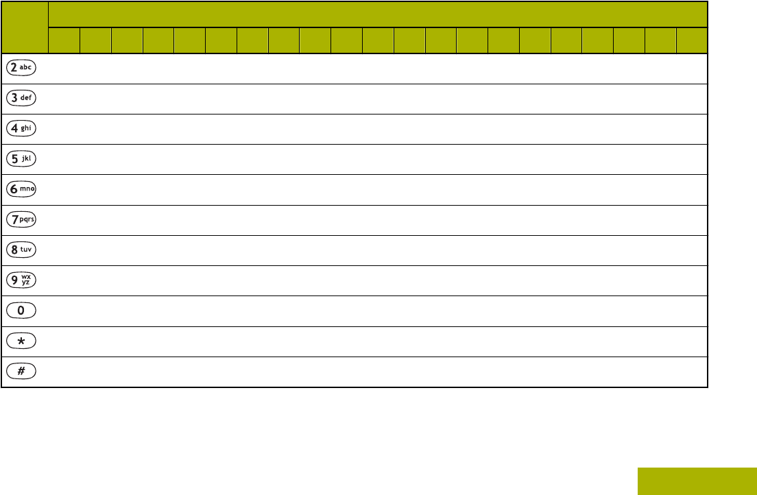
Key Number of Times Key is Pressed
1 2 3 4 5 6 7 8 9 10 11 12 13 14 15 16 17 18 19 20 21
abc
def
ghi
j k l
m n o
p q r s
t u v
w x y z
Toggle between mixed case mode, uppercase mode and lowercase mode.
Space
Toggle between numeric and letter mode.
Identifying Radio Controls
31
English
Draft
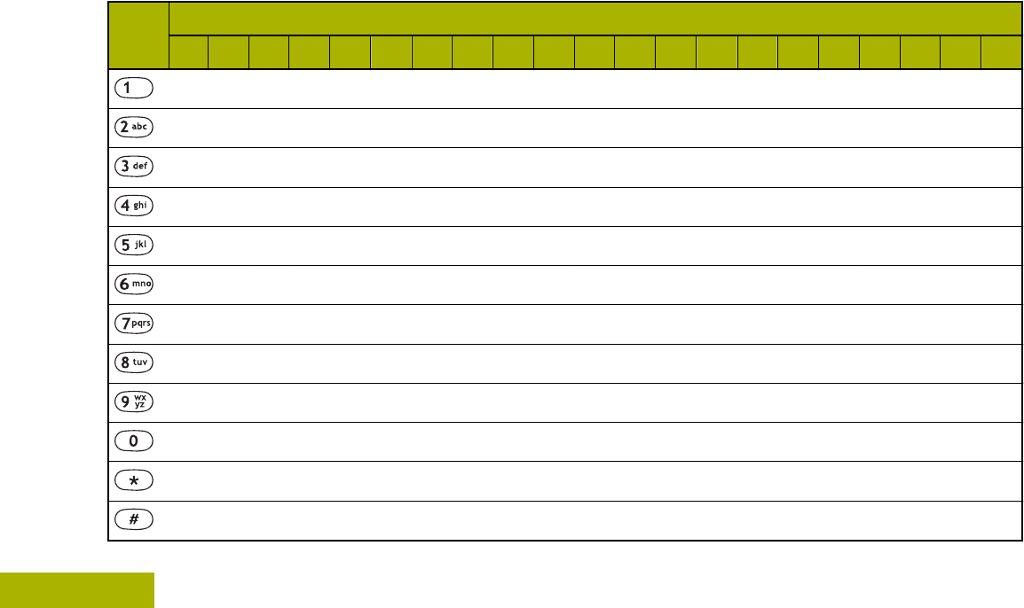
Keypad Characters – Numeric Mode
Key Number of Times Key is Pressed
1 2 3 4 5 6 7 8 9 10 11 12 13 14 15 16 17 18 19 20 21
1 . , ? ! ; @ _ - * # & $ / + = \ “ ‘ ( )
2
3
4
5
6
7
8
9
0
Space
Toggle between numeric and letter mode.
Identifying Radio Controls
32
English
Draft
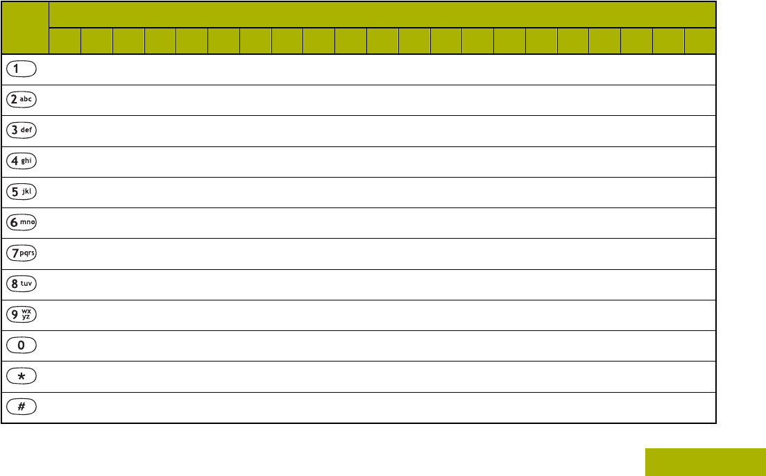
Keypad Characters – Hexadecimal Mode
Key Number of Times Key is Pressed
1 2 3 4 5 6 7 8 9 10 11 12 13 14 15 16 17 18 19 20 21
1
2 A B C
3 D E F
4
5
6
7
8
9
0
Not applicable
Not applicable
Identifying Radio Controls
33
English
Draft
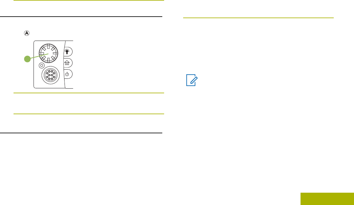
Push-To-Talk (PTT) Button
A
The PTT button on the side of the microphone
serves two basic purposes:
•While a call is in progress, the PTT button allows
the radio to transmit to other radios in the call.
Press and hold down PTT button to talk. Release
the PTT button to listen. The microphone is
activated when the PTT button is pressed.
•While a call is not in progress, the PTT button is
used to make a new call. See Methods to Make a
Radio Call on page 51 for more information.
Identifying Radio Controls
34
English
Draft
Identifying Status Indicators
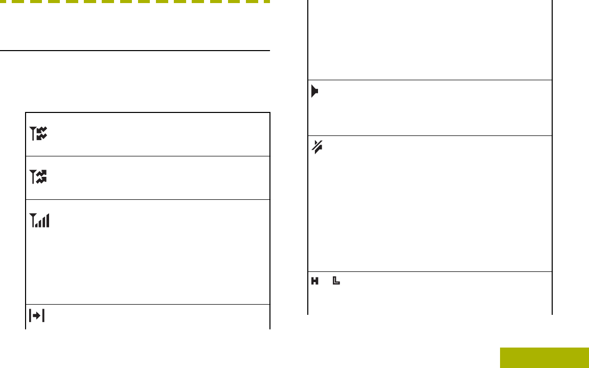
Status Icons
The liquid crystal display (LCD) of your radio shows
the radio status, text entries, and menu entries. The
following are the icons that appear on the display of
the radio.
Receiving
Radio is receiving a call or data.
Transmitting
Radio is transmitting a call or data.
Received Signal Strength Indicator
(RSSI)
The number of bars displayed repre-
sents the received signal strength for the
current site, for trunking only. The more
stripes in the icon, the stronger the sig-
nal.
Direct
On – Radio is currently configured for di-
rect radio-to-radio communication (dur-
ing conventional operation only).
Off – Radio is connected with other ra-
dios through a repeater.
Monitor (Carrier Squelch)
Selected channel is being monitored
(during conventional operation only).
In-Call User Alert
On – The feature is enabled. Voice mut-
ing of the affiliated trunking talkgroup or
selected conventional channel is activa-
ted.
Off – The feature is disabled. Voice mut-
ing of the affiliated trunking talkgroup or
selected conventional channel is deacti-
vated.
or Power Level
L – Radio is set at Low power.
Identifying Status Indicators
35
English
Draft
H – Radio is set at High power.
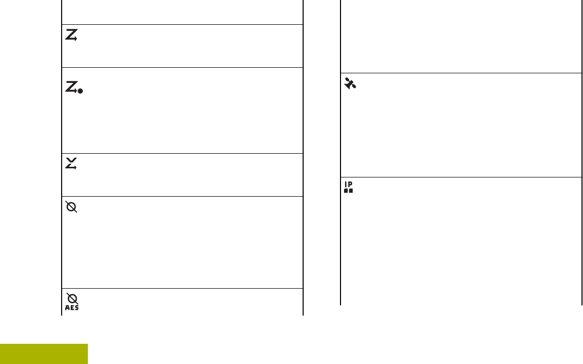
Scan
Radio is scanning a scan list.
Priority Channel Scan
Blinking dot – Radio detects activity on
channel designated as Priority-One.
Steady dot – Radio detects activity on
channel designated as Priority-Two.
Vote Scan Enabled
The vote scan feature is enabled.
Secure Operation
On – Secure operation.
Off – Clear operation.
Blinking – Receiving an encrypted
voice call.
AES Secure Operation
On – AES secure operation.
Off – Clear operation.
Blinking – Receiving an encrypted
voice call.
GPS Signal
On – Feature is enabled and signal is
available.
Off – Feature is disabled.
Blinking – Feature is enabled, but no
signal is available.
User Login Indicator (IP Packet Data)
On – User is currently associated with
the radio.
Off – User is currently not associated
with the radio.
Blinking – Device registration or user
registration with the server failed due to
an invalid username or pin.
Identifying Status Indicators
36
English
Draft
Inverted – User successfully login to the
secured IP Packet Data.
Data Activity
Data activity is present.
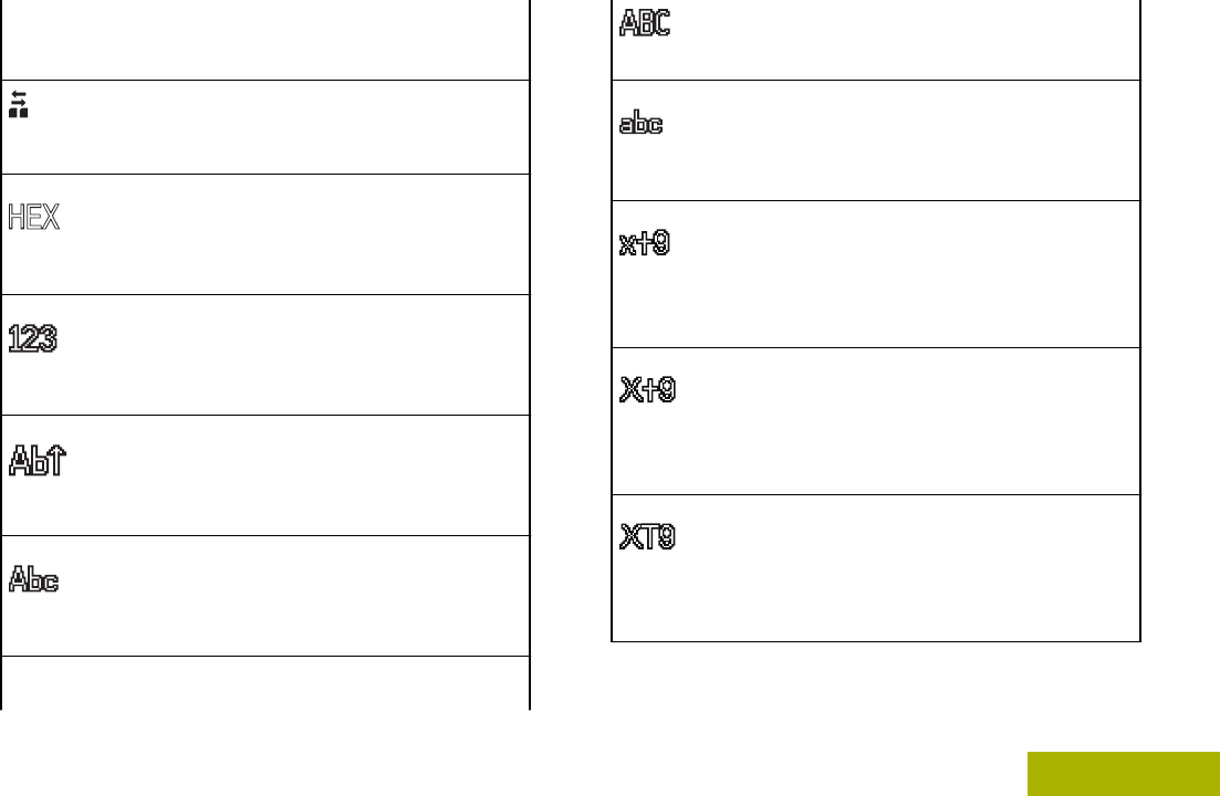
Hexadecimal
Indicates that the text entry is currently
in hexadecimal mode.
Numeric
Indicates that the text entry is currently
in numeric mode.
Start Case
Indicates that the first character of the
text entry is capitalized.
Mixed Case
Indicates that the text entry is currently
in normal text mode.
Uppercase
Indicates that the text entry is currently
in uppercase mode.
Lowercase
Indicates that the text entry is currently
in lowercase mode.
Lowercase Predictive
Indicates that the text entry is currently
in lowercase and with predicted words
shown at the bottom of the screen.
Mixedcase Predictive
Indicates that the text entry is currently
in mixed case and with predicted words
shown at the bottom of the screen.
Uppercase Predictive
Indicates that the text entry is currently
in uppercase and with predicted words
shown at the bottom of the screen.
Identifying Status Indicators
37
English
Draft
The radio Wi-Fi® network is connected.
The number of bars displayed repre-
sents the signal strength of the Wi-Fi
signal.
Text Messaging Service (TMS) Indicators
This feature allows you to send and receive text
messages. Status icons and menu options shown
here help you to work more efficiently with TMS
feature. See Text Messaging Service (TMS) on page
85 for more information.
TMS Status Icons
The following icons appear on the radio’s display
when you send and receive text messages.
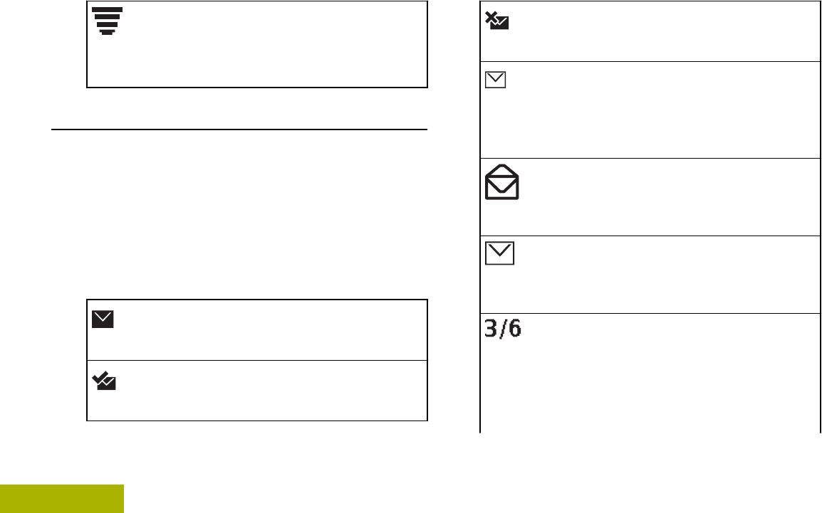
Inbox Full
The Inbox is full.
Message Sent
The text message is sent successfully.
Message Unsent
The text message cannot be sent.
Unread Message
• User receives a new message.
• The selected text message in the Inbox
has not been read.
Read Message
The selected text message in the Inbox
has been read.
Normal Message
User is composing a message with normal
priority and without a request for a reply.
Message Index
Indicates the index of the current message
the user is viewing.
Example: If the user is looking at the third
message out of a total of 6 messages in
Identifying Status Indicators
38
English
Draft
the Inbox folder, the icon is displayed as
the icon on the left column.
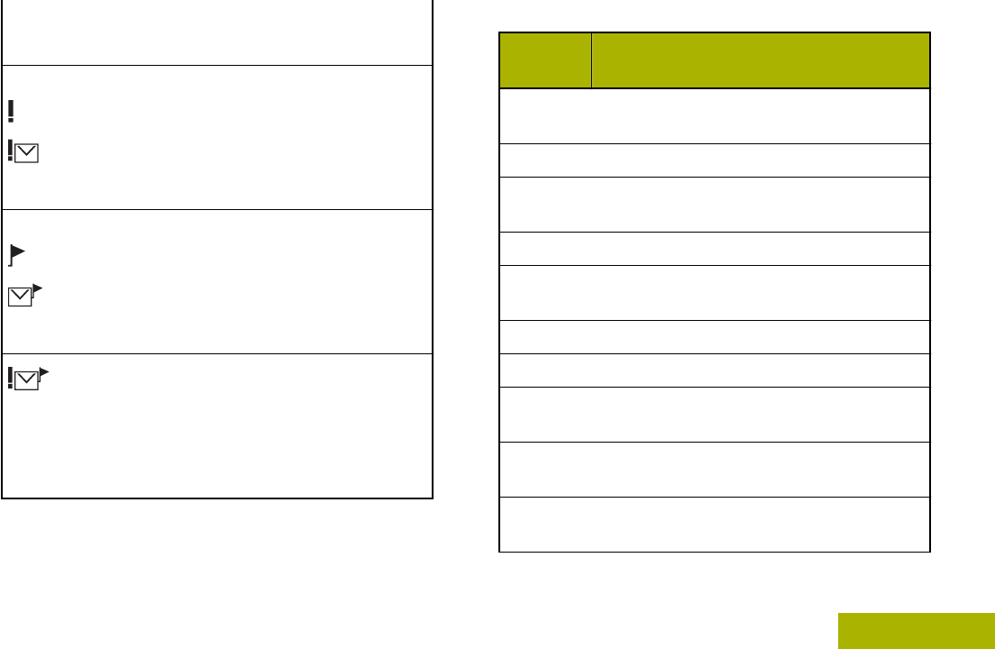
Priority Status
• The “Priority” feature is toggled on be-
fore the message is sent.
• Messages in the Inbox folder are flag-
ged with “Priority”.
Request Reply
• The “Request Reply” feature is toggled
on before the message is sent.
• Messages in the Inbox folder are flag-
ged with “Request Reply”.
Priority Status and Request Reply
• User is composing a message with a
priority status and a request for a reply.
• Messages in the Inbox folder are flag-
ged with “Priority” and “Request Reply”.
TMS Menu Options
Menu
Option Description/Function
INBX Brings you to your incoming messages
screen.
COMP Brings you to the compose screen.
DRFT Brings you to the saved message
screen.
BACK Brings you back to the previous screen.
SAVE Saves the messages you have edited to
the Draft folder.
SENT Brings you to the sent messages screen.
NEW Creates a new message.
LIST Brings you to the predefined messages
screen.
IMPT Toggles the “Priority Status” icon on or
off for an outgoing message.
RQRP Toggles “Request Reply” icon on or off
for an outgoing message.
Identifying Status Indicators
39
English
Draft
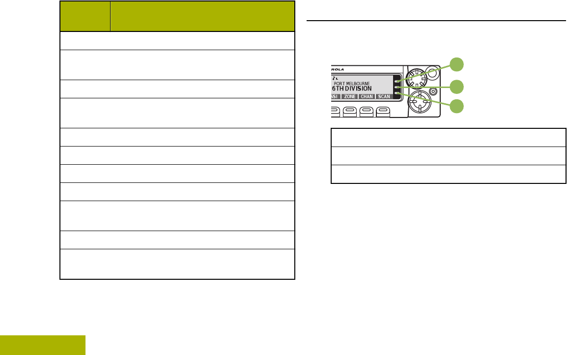
Menu
Option Description/Function
CURR Deletes the current selected message.
ALL Selects to delete all the messages in the
current folder.
DEL Deletes a message or text.
EDIT Edits a draft message or key in a target
address.
EXIT Exits to the Home screen.
NO Cancel the delete all messages options.
OPTN Brings you to the Options main screen.
RPLY Replies to a message.
SEL Selects a predefined message or ad-
dress.
SEND Sends the message.
YES Deletes all the messages in the current
folder.
LED Indicator
The LED indicator shows the operational status of
your radio.
A
B
C
A Red LED
B Yellow LED
C Green LED
Solid red Radio is transmitting.
Rapidly blinking
red Radio has failed the self test
upon powering up or
encountered a fatal error.
Solid yellow
(Conventional
Only)
Channel is busy.
Identifying Status Indicators
40
English
Draft
Blinking yellow Radio is receiving a secured
transmission.
Solid green Radio is powering up, or is on
a non-priority channel while in
the Scan List Programming
mode.
Blinking green Radio is receiving an individual
or telephone call, or is on a
Priority-Two channel while in
the Scan List Programming
mode.
Rapidly blinking
green Radio is on a Priority-One
channel while in the Scan List
Programming mode.
Intelligent Lighting Indicators
This feature temporarily changes the display backlight color and the alert text background color of the radio to help
signal that a radio event has occurred.
Note:
This feature must be preprogrammed by a qualified radio technician.
Backlight and Bar
Color Notification When
Orange Emergency Alerts The radio initiates an emergency alarm or call.
The radio receives an emergency alarm or call.
Identifying Status Indicators
41
English
Draft
Backlight and Bar
Color Notification When
Red Critical Alerts The radio battery is low.
The radio is out of range.
The radio enters Failsoft mode.
The radio is unable to establish a full connection with the system.
The radio is unable to authenticate or register with the system.
The radio lost GPS signal or GPS function fails.
Green Call Alerts The radio receives a private call.
The radio receives a phone call.
The radio receives a call alert.
The radio receives a selective call.
The radio enters Geofence.
Identifying Status Indicators
42
English
Draft

Alert Tones
Your radio uses alert tones to inform you of the condition of your radio. The following table lists these tones and
when they occur.
You Hear Tone Name Heard
Short, Low-
Pitched Tone Radio Self Test Fail When radio fails its power-up self test.
Reject When an unauthorized request is made.
Time-Out Timer Warning Four seconds before time out.
No ACK Received When radio fails to receive an acknowledgment.
Individual Call Warning
Tone When radio is in an individual call for greater than 6 seconds
without any activity.
Long, Low-
Pitched Tone Time-Out Timer Timed Out After time out.
Talk Prohibit/PTT Inhibit (When PTT button is pressed) transmissions are not allowed.
Lack of Voice PTT Time out When the radio ends your call after it detected there are lack of
voice for 5 seconds after the PTT is pressed and hold. Your ra-
dio ends the call to enable your radio to receive calls from other
radio users.
Out of Range (When PTT button is pressed) the radio is out of range of the
system.
Invalid Mode When radio is on an unpreprogrammed channel.
Identifying Status Indicators
43
English
Draft

You Hear Tone Name Heard
A Group of
Low-Pitched
Tones
Busy When system is busy.
Short, Medium-
Pitched Tone Valid Key-Press When a correct key is pressed.
Radio Self Test Pass When radio passes its power-up self test.
Clear Voice At beginning of a non-coded communication.
Priority Channel Received When activity on a priority channel is received.
Emergency Alarm /Call En-
try When entering the emergency state.
Central Echo When central controller has received a request from a radio.
Long, Medium-
Pitched Tone Volume Set When volume is changed on a quiet channel.
Emergency Exit When exiting the emergency state.
A Group of Me-
dium-Pitched
Tones
Failsoft When the trunking system fails.
Automatic Call Back When voice channel is available from previous request.
Keyfail When encryption key has been lost.
Console Acknowledge When status, emergency alarm, or reprogram request ACK is re-
ceived.
Identifying Status Indicators
44
English
Draft
You Hear Tone Name Heard
Received Individual Call When Call Alert or Private Call is received.
Call Alert Sent When Call Alert is received by the target radio.
Site Trunking When a SmartZone trunking system fails.
Short, High-
Pitched Tone
(Chirp)
Low-Battery Chirp When battery is below preset threshold value.
Two High-
Pitched Tones GPS Fails When the GPS signal is lost or when GPS fails.
Ringing Fast Ringing When system is searching for target of Private Call.
Enhanced Call Sent When waiting for target of Private Call to answer the call.
Phone Call Received When a land-to-mobile phone call is received.
Gurgle Dynamic Regrouping (When PTT button is pressed) a dynamic ID has been received.
Talk Permit (When PTT button is pressed) is verifying with the system for ac-
cepting its transmissions.
Unique, Low-
Pitched Chirp New Message When a new message is received.
Unique, High-
Pitched Chirp Priority Status When a priority message is received.
Identifying Status Indicators
45
English
Draft

General Radio Operation
Selecting a Zone
Your radio must be preprogrammed to allow you to
use this feature.
A zone is a group of channels. The following methods
are options on how to select a radio zone. The result
of all the methods is the same. You can use the
options interchangeably depending on your
preference and the programmed functions.
•Select a zone via the Mode Knob:
a) Rotate the Mode Knob until the display shows
the desired zone.
•Select a zone via the radio menu ZONE:
a) or to ZONE and press the Menu Select
button directly below ZONE.
b) or to the required zone, or use the keypad to
enter the zone number.
c) Press or the PTT button to confirm the
selected zone number.
d) Press the PTT button to transmit on the
displayed zone channel.
Selecting a Radio Channel
A channel is a group of radio characteristics, such as
transmit/ receive frequency pairs. The following
methods are options on how to select a radio
channel. The result of all the methods is the same.
You can use the options interchangeably depending
on your preference and the programmed functions.
•Select a channel via the Mode knob:
a) Rotate the Mode knob until the display shows
the desired channel.
b) Press the PTT button to begin transmitting on
the displayed channel.
•Select a channel via the radio menu CHAN:
a) or to CHAN.
b) Press the Menu Select button directly below
CHAN.
c) or to the required channel.
d) Press the Menu Select button directly below
SEL to confirm the selected channel.
General Radio Operation
46
English
Draft

e) Press the PTT button to transmit on the
displayed zone channel.
Selecting a Channel via Channel Search
Button
This feature allows you to do a quick search for a
specific channel in your radio by keying in the alias of
the channel. If the name matches, your radio prompts
the first found matched channel name.
1Perform one of the following actions:
•Press the preprogrammed Channel Search
button.
• or to CHSR and press the Menu Select
button directly below CHSR.
A blinking cursor appears on the Channel Search
screen.
2Use the keypad to type or edit your channel
name.
3To initiate searching, press the Menu Select
button directly below CHSR once the entry is done.
To exit this procedure, press the Menu Select
button directly below CNCL.
The display shows SEARCHING. Once found, the
display shows the matched channel name and the
radio changed its transmission to the selected
channel.
If the radio is triggered to search for an empty entry,
the display shows INVALID ENTRY. Repeat step 2 to
search again.
If the entry does not match, the display shows
CHANNEL NAME NOT FOUND. Repeat step 2 to search
again; or press or the Menu Select button directly
below EXIT to exit.
Mode Select Feature
Mode Select allows a long press to save the current
zone and channel of your radio to a programmable
button, keypad button, or a softkey; then once
programmed, the short-press of that button or softkey
changes the transmission to the saved zone and
channel.
There are two methods to save the selected zone and
channel:
General Radio Operation
47
English
Draft
• Softkeys
• Programmable buttons and keypad buttons (digit 0
to 9)
Note:
Your radio must be preprogrammed to allow
you to use this feature.
Saving a Zone and a Channel to a Softkey
Five softkeys are available for you to save the
frequently used zone and channel.
1Toggle your zone and channel to the required
zone and channel.
2 or to MS1, MS2 ... or MS5.
3Press and hold the Menu Select button directly
below one of the softkey (MS1 – MS5).
You hear a short, medium-pitched tone when the
zone and channel is saved.
Note:
To change the programmed zone and
channel, repeat this procedure.
Short press of the programmed softkey
changes your current transmission to the zone
and channel programmed in this softkey.
Saving a Zone and a Channel to a Button
You can save the frequent used zone and channel to
the programmable buttons and keypad digit 0 to 9
buttons.
1Toggle your zone and channel to the required
zone and channel.
2Press and hold the button you desire to program.
You hear a short, medium-pitched tone when the
zone and channel is saved.
Note:
Repeat this procedure to change the zone and
channel of the programmed button.
Short press of the programmed button
changes your current transmission to the zone
and channel programmed in this button.
General Radio Operation
48
English
Draft
Receiving and Responding to a Radio Call
Once you have selected the required channel and/or
zone, you can proceed to receive and respond to
calls.
A
B
C
A Red LED
B Yellow LED
C Green LED
The LED lights up solid red while the radio is
transmitting. In conventional mode, the LED lights up
solid yellow when the radio is receiving a
transmission. In trunking mode, there is no LED
indication when the radio receives a transmission.
If the radio is receiving a secure transmission, the
LED blinks yellow.
Receiving and Responding to a Talkgroup Call
To receive a call from a group of users, your radio
must be configured as part of that talkgroup.
When you receive a talkgroup call (while on the Home
screen) the radio triggers for your attention with one
of the following scenarios depending on the system
your radio is configured:
• For ASTRO Conventional system, the LED lights
up solid yellow. The display shows the talkgroup
alias or ID, and the caller alias or ID.
• For Trunking system, the display shows the caller
alias or ID.
1Hold the microphone vertically 1 to 2 inches (2.5 to
5.0 cm) from your mouth.
2Press the PTT button to respond to the call.
The LED lights up solid red.
3Release the PTT button to listen.
See also Making a Talkgroup Call on page 51 for
details on making a Talkgroup Call.
General Radio Operation
49
English
Draft

Receiving and Responding to a Private Call (Trunking
Only)
A Private Call is a call from an individual radio to
another individual radio.
The one-to-one call between the two radios are not
heard by the others in the current talkgroup. The
calling radio automatically verifies that the receiving
radio is active on the system and can display the
caller ID.
Note:
With the inactivity timer enabled (optional),
when there is no response from the receiving
radio, the calling radio exits the call with Menu
Inactive Exit tone after the timer expires.
When you receive a Private Call, you hear two alert
tones and the LED blinks green. The display shows
CALL RECEIVED and the caller alias or ID.
1Press the Menu Select button directly below RESP
within 20 seconds after the call indicators begin.
If the caller alias is in the call list, the display
shows the caller alias during the call.
If the caller name is not in the call list, the display
shows the caller ID.
2Press and hold the PTT button to talk. Release the
PTT button to listen.
3Press to hang up and return to the Home
screen.
Note:
If you press PTT button before pressing the
Menu Select button directly below RESP, your
conversation will be heard by all members of
the talk group.
If 20 seconds pass before you press the Menu
Select button directly below the RESP, you will
not respond privately to the call just received.
Instead, you initiate a Private Call.
See also Making a Private Call (Trunking Only) on
page 52 for details on making a Private Call.
Receiving and Responding to a Telephone Call
(Trunking Only)
This feature allows you to receive calls similar to
standard phone calls from a landline phone.
Note:
With the inactivity timer enabled (optional), if
there is no response to the call after the timer
General Radio Operation
50
English
Draft
expires, your radio exits the call with Menu
Inactive Exit tone.
When you receive a Telephone Call, you hear a
telephone-type ringing and the LED blinks green. The
backlight of the screen turns green.The display shows
PHONE CALL and the call received icon blinks.
1Press the Menu Select button directly below
RESP.
2Press and hold the PTT button to talk. Release the
PTT button to listen.
3Press or the Menu Select button directly below
EXIT to hang up and return to the Home screen.
See also Making a Telephone Call (Trunking Only) on
page 53 for details on making a Telephone Call.
Methods to Make a Radio Call
You can select a zone, channel, subscriber ID, or
talkgroup by using:
• The preprogrammed Zone menu.
•The Mode Knob.
•A preprogrammed One Touch button.
• The Contacts list (see Contacts on page 65).
Note:
The radio automatically exits the feature, if the
feature inactivity timer is enabled, when the
radio is left idle and the timer expires. You will
hear the Menu Inactive Exit Tone upon feature
exit.
Making a Talkgroup Call
To make a call to a group of users, your radio must
be configured as part of that talkgroup.
1Perform one of the following actions:
• or to TGRP and press the Menu Select
button directly below TGRP. The display shows
the last-selected talkgroup. Press the Menu
Select button directly below SEL.
•Use the Mode Knob to select the channel with
the desired talkgroup.
2Hold the microphone vertically 1 to 2 inches (2.5 to
5.0 cm) from your mouth.
3Press the PTT button to make the call.
The radio shows different indicators based on the
system the radio is configured.
General Radio Operation
51
English
Draft

• For ASTRO Conventional system, the LED
lights up solid red. The display shows the
talkgroup alias or ID.
• For Trunking system, the LED lights up solid
red.
4Speak clearly into the microphone.
5Release the PTT button to listen.
Making a Private Call (Trunking Only)
Your radio must be preprogrammed to allow you to
use this feature.
This feature allows you to send an individual Call
Alert or page if there is no answer from the target
radio. See Sending a Call Alert Page on page 76 for
more information.
1Perform one of the following actions:
• To access this feature via a preprogrammed
button, press the preprogrammed Quick
Access (One-Touch) Private Call button to
dial the preprogrammed ID (number) and
initiate the Private Call. Proceed to step 5.
• To access this feature via the menu, proceed
to the next step.
2 or to CALL, and press the Menu Select button
directly below CALL.
The display shows the last transmitted or received
ID.
3To select the required ID, perform one of the
following actions:
•Press the Menu Select button directly below
CNTS to scroll through and select the required
ID.
•Press the Menu Select button directly below
LIST to go to the first number of the call list.
• or to the required ID.
•Use the keypad to enter the required ID.
4Press the PTT button to initiate the Private Call.
A telephone-type ringing sounds if the receiving
unit is in service. The display shows CALLING...
<NUMBER> or CALLING... <ALIAS>.
5Hold the microphone vertically 1 to 2 inches (2.5 to
5.0 cm) from your mouth.
General Radio Operation
52
English
Draft
When you are connected, the display shows the
ID of the target radio.
If no acknowledgment is received, the display
shows NO ACKNOWLEDGE.
If the target radio does not respond before the
time out, the display shows NO ANSWER.
6Press and hold the PTT button to talk. Release the
PTT button to listen.
7Press to return to the Home screen.
Making a Telephone Call (Trunking Only)
This feature allows you to make calls similar to
standard phone calls to a mobile or landline phone.
1Perform one of the following actions:
• To access this feature via a preprogrammed
button, press the preprogrammed Quick
Access (One-Touch) Phone Call button to
dial the preprogrammed phone number.
Proceed to step 5.
• To access this feature via the menu, proceed
to the next step.
2 or to PHON, and press the Menu Select button
directly below PHON.
The display shows the last transmitted or received
ID.
3To select the required ID, perform one of the
following actions:
•Press the Menu Select button directly below
CNTS to scroll through and select the required
ID.
•Press the Menu Select button directly below
LIST to go to the first number of the call list.
• or to the required phone number.
• Use the keypad to enter the required phone
number.
4Press the PTT button to dial the phone number.
5Hold the microphone vertically 1 to 2 inches (2.5 to
5.0 cm) from your mouth.
6When your call is answered, press and hold the
PTT button to talk. Release the PTT button to
listen.
General Radio Operation
53
English
Draft

7Press to return to the Home screen.
See Alert Tones on page 43 for more information if
your call is NOT answered.
Switching Between Repeater or Direct
Operation Button
The Repeater Operation increases the radio
coverage area by connecting with other radios
through a repeater. The transmit and receive
frequencies are different.
The Direct or “talkaround operation” allows you to
bypass the repeater and connect directly to another
radio. The transmit and receive frequencies are the
same.
Perform one of the following actions:
•Press the preprogrammed Repeater/Direct
switch to toggle between talkaround and
repeater modes.
• or to DIR and press the Menu Select button
directly below DIR.
The display shows REPEATER MODE if the radio is
currently in Repeater mode.
The display shows DIRECT MODE and the Talkaround
icon if the radio is currently in Direct mode (during
conventional operation only).
Monitor Feature
Radio users who switch from analog to digital radios
often assume that the lack of static on a digital
channel is an indication that the radio is not working
properly. This is not the case.
Digital technology quiets the transmission by
removing the noise from the signal and allows only
the clear voice or data information to be heard.
Use the Monitor feature to make sure a channel is
clear before transmitting.
Monitoring a Channel
•Monitoring a Channel in Conventional Modes:
a) Lift the microphone off hook.
b) Listen for activity on that channel.
c) Adjust the Volume Knob if necessary.
General Radio Operation
54
English
Draft

d) If you hear no activity, press and hold the PTT
button to start your conversation.
•Monitoring a Channel in Trunked Modes:
a) Lift the microphone off hook.
b) Press the PTT button.
c) If you hear two, short, high-pitched tones, or if
you hear no tone and the indicator lights
steadily, then proceed with your message.
d) Release the PTT button to receive (listen).
If you are not in the range of the system, you may
hear a continuous low-pitched tone and the display
shows OUT OF RANGE.
Monitoring Conventional Mode
This feature must first be enabled by a qualified radio
technician or system administrator.
This feature allows you to monitor channel traffic on
conventional channels by defeating the coded
squelch. Thus, you can to listen to another user
active on the channel. This way, you may be
prevented from talking over someone else’s
conversation.
1To activate monitoring, perform one of the
following actions:
• At Home mode where the default zone and
channel are being displayed, or to MON and
press the Menu Select button directly below
MON momentarily.
• Take the control head off hook.
The display shows MONITOR ON. You hear all
channel traffic.
2Press the Menu Select button again to deactivate
the monitoring.
The display shows MONITOR OFF.
MONITOR ON shown on the display indicates that the
radio is monitoring. Pressing the Menu Select button
again turns monitor off and you don’t hear all channel
traffic. If you try to transmit on a receive-only channel,
you hear an invalid tone until you release the PTT
button.
General Radio Operation
55
English
Draft
Advanced Features
Advanced Call Features
Calling a Phone Not in the List
1 or to PHON.
2Press the Menu Select button directly below
PHON.
3Enter the desired phone number on the keypad.
The display updates as the numbers are entered.
4Press the button or the PTT button on the
keypad microphone to make the call.
5Press and hold the PTT button to talk. Release the
PTT button to listen.
6Press or Menu Select button directly below
PHON to exit.
Selective Call (ASTRO Conventional Only)
This feature allows you to receive a call from or to call
a specific individual. It is intended to provide privacy
and to eliminate the annoyance of having to listen to
conversations that are of no interest to you.
Receiving a Selective Call
When you receive a Selective Call, you hear two alert
tones and the LED lights up solid yellow. The call
received icons blink and the display alternates
between CALL RECEIVED and the home display.
The speaker unmutes.
1Hold the microphone vertically 1 to 2 inches (2.5 to
5.0 cm) from your mouth.
2Press and hold the PTT button to talk. Release the
PTT button to listen.
Note:
If you press PTT button before pressing the
Menu Select button directly below CALL,
your conversation is heard by all members
of the talk group.
If 20 seconds pass before you press the
Menu Select button directly below the
CALL, you are not responding privately to
the call just received. Instead, you initiate a
Advanced Features
56
English
Draft
Selective Call. See Making a Selective Call
on page 57.
Making a Selective Call
1Perform one of the following actions:
• To access this feature via a preprogrammed
button, press the preprogrammed Quick
Access (One-Touch) Selective Call button to
dial the preprogrammed ID. Proceed to step 4.
• To access this feature via the menu, proceed
to the next step.
2 or to CALL, and press the Menu Select button
directly below CALL.
The display shows the last transmitted or received
ID.
3To select the required ID, perform one of the
following actions:
•Press the Menu Select button directly below
CNTS to scroll through and select the required
ID.
•Press the Menu Select button directly below
LIST to go to the last number dialed.
• or to the required ID.
• Use the keypad to enter the required ID.
4Hold the microphone vertically 1 to 2 inches (2.5 to
5.0 cm) from your mouth.
5Press and hold the PTT button to start the
Selective Call.
The display shows the ID of the target radio.
6Release the PTT button to listen.
7Press to return to the Home screen.
If you do not press button to hang up, your
radio will remain in Selective Call state with the
other unit. You will miss all subfleet traffic and
incoming phone calls.
Talkgroup Call Feature (Conventional Operation Only)
This feature allows you to define a group of
conventional system users so that they can share the
use of a conventional channel.
Advanced Features
57
English
Draft
Note:
Encryption keys are associated to talkgroups.
When talkgroups are associated, encryption
keys are changed by changing the active
talkgroup. See Secure Operations on page
95 for more information.
Selecting a Talkgroup
1 or to TGRP and press the Menu Select button
directly below TGRP.
The display shows the last Talkgroup that was
selected and stored.
2Perform one of the following actions:
• or to PSET for the preset preprogrammed
Talkgroup.
• or to the required Talkgroup.
3Press the Menu Select button directly below SEL
to save the currently selected Talkgroup and
return to the Home screen.
If the encryption key associated to the new
Talkgroup is erased, you hear a momentary key
fail tone and the display shows KEY FAIL.
If the encryption key that is associated to the new
Talkgroup is not allowed, you hear a momentary
key fail tone and the display shows ILLEGAL KEY.
4Press to return to the Home screen.
Sending a Status Call
This feature allows you to send data calls to the
dispatcher about a predefined status.
Each status can have up to a 14-character name. A
maximum of eight status conditions is possible.
Note:
The radio automatically exits the feature, if the
feature inactivity timer is enabled, when the
radio is left idle and the timer expires. You will
hear the Menu Inactive Exit Tone upon feature
exit.
1Perform one of the following actions:
•Press the preprogrammed Status button.
• or to STS and press the Menu Select button
directly below STS.
The display shows the last acknowledged status
call, or the first status in the list.
Advanced Features
58
English
Draft
2Perform one of the following actions:
• or to the required status.
•Use the keypad to enter a number
corresponding to the location in the status list.
3Press the PTT button to send the status.
When the dispatcher acknowledges, you hear four
tones and the display shows ACK RECEIVED . The
radio returns to normal dispatch operation.
If no acknowledgment is received, you hear a low-
pitched tone and the display shows NO
ACKNOWLEDGE.
4Press to return to the Home screen.
No traffic is heard on trunked channels while
Status Calls is selected. If the radio detects no
Status Call activity for six seconds, an alert tone
sounds until you press or the PTT button.
Responding to the Dynamic Regrouping Feature
(Trunking Only)
This feature allows the dispatcher to temporarily
reassign selected radios to a particular channel where
they can communicate with each other. This feature is
typically used during special operations and is
enabled by a qualified radio technician.
You will not notice whether your radio has this feature
enabled until a dynamic regrouping command is sent
by the dispatcher.
Note:
If you try to access a zone or channel that has
been reserved by the dispatcher as a
dynamically regrouped mode for other users,
you hear an invalid tone.
When your radio is dynamically regrouped, it
automatically switches to the dynamically regrouped
channel. You hear a Gurgle tone and the display
shows the dynamically regrouped channel’s name.
Press the PTT button to talk. Release PTT button
to listen.
When the dispatcher cancels dynamic regrouping, the
radio automatically returns to the zone and channel
that you were using before the radio was dynamically
regrouped.
Requesting a Reprogram (Trunking Only)
This feature allows you to notify the dispatcher when
you want a new dynamic regrouping assignment.
Advanced Features
59
English
Draft

Perform one of the following actions:
•Press the preprogrammed Reprogram
Request button to send reprogram request to
the dispatcher.
• or to RPGM then press the Menu Select
button directly below RPGM to send reprogram
request to the dispatcher.
The display shows REPROGRAM RQST and PLEASE
WAIT.
If you hear five beeps, the dispatcher has
acknowledged the reprogram request. The display
shows ACK RECEIVED and the radio returns to the
Home screen.
If the dispatcher does not acknowledge the
reprogram request within six seconds, you hear a
low-pitched alert tone and the display shows NO
ACKNOWLEDGE. Try again or press to cancel and
return to the Home screen.
Classification of Regrouped Radios
The dispatcher can classify regrouped radios into
either of two categories:
Select
Enabled Select-enabled radios are free to
change to any available channel,
including the dynamic-regrouping
channel, once the user has selected
the dynamic-regrouping position.
Select
Disabled Select-disabled radios cannot change
channels while dynamically regrouped.
The dispatcher has forced the radio to
remain on the dynamic-regrouping
channel.
The Scan or Private Call feature cannot be selected
while your radio is Select Disabled.
Dynamic Zone Programming (DZP)
Note:
Your radio must be preprogrammed to allow
you to use this feature. This feature works on
the condition at least one zone in the radio
must be a non-dynamic zone.
This feature provides one or more Dynamic Zones to
store frequently used channels be it conventional or
trunking. These dynamic channels are saved from
pre-existing (non-dynamic) channels in the radio. This
saves the time and effort from the regular navigation
Advanced Features
60
English
Draft
around the working zones and channels. User can
also delete or update the list in the Dynamic Zone.
Entering the Dynamic Zone to Select a Dynamic
Channel
1 or to Zone then press the Menu Select button
directly below Zone.
The display shows the Zone screen.
2 or to <# Dynamic Zone Channels>
3Perform one of the following actions:
•Press the Menu Select button below Sel to
select.
•Press the Menu Select button below Exit to
exit.
If you have selected one of the Dynamic Zone
Channels list, the display returns to Home screen
with the selected <# Dynamic Zone Channels>
shown on the screen.
If you have selected Exit without selecting any
Dynamic Zone Channels list, the display returns to
Home screen without any changes.
Saving a Channel in the Dynamic Zone from List
Selection
The radio must be in Dynamic Zone in order to
perform this operation.
1 or to ZnPr. Press the Menu Select button
directly below ZnPr to enter Program Zone
screen.
2Press the Menu Select button directly below
Edit.
The display shows Search Options screen.
3 or to List Selection. Press the Menu Select
button directly below SEL.
The display shows Select Zone screen.
4 or to the required zone. Press the Menu Select
button directly below SEL.
The display shows Select Chan screen.
5 or to the required channel. Press the Menu
Select button directly below SEL.
The display shows Channel updated.
Advanced Features
61
English
Draft

6Press the Menu Select button directly below Exit
to return to Home screen.
Deleting a Channel in the Dynamic Zone
The radio must be in Dynamic Zone in order to
perform this operation.
1 or to ZnPr then press the Menu Select button
directly below ZnPr to enter Program Zone
screen.
The display shows the dynamic channels list.
2 or to the saved dynamic channel then press the
Menu Select button directly below Del.
The display shows Channel deleted screen.
3Press the Menu Select button below Exit to
return to Home screen.
The Home screen shows <Dynamic Zone
Channels>.
If the channel deleted is the Home channel, the
Home screen shows <Zone Name>+”Blank”.
Multiple Control Head Features
This feature allows your transceiver to control a
combination of up to four O5 control heads on APX
Mobile (depending on the model). You can use the
CAN cables to connect in any configuration that does
not exceed 131 feet (40 meters) in combined length.
Refer the Control Head Installation Manual
(6878215A01) for further information.
The Multiple Control Head (MCH) feature consists of
2 modes that can be programmed via Customer
Programming Software (CPS):
• All Active mode
• One Active mode
Note:
If two or more control heads are connected to
the system before enabling the MCH feature in
the CPS, the radio displays EXTRA CH or CH
ID # ERR. Both errors are FATAL.
Setting the ID of the Initial Control Head
This feature allows you to setup the control head in
the Front Panel Programming (FPP) mode. During
the setup, the control heads are defined as Control
Advanced Features
62
English
Draft

Head Number 1, Control Head Number 2, Control
Head Number 3 and Control Head Number 4.
1Power off the radio by pressing the Power button.
2Press and hold the left-most Menu Select button
and the emergency button simultaneously.
3While continuing to depress these two buttons,
press the Power button to power on the radio and
the control head.
The radio and the control head powers on into
FPP mode. The display shows the ID number of
the control head.
4Turn the Mode knob to change the ID number of
the control head.
5Press the Power button to power off the radio and
exit FPP mode.
6Repeat step1 to step 5 to set the ID number for
the rest of the attached control heads.
All Active Mode
The All Active mode enables all connected control
heads attached to the radio to operate concurrently
with each other. When you activate a feature on one
control head, the rest of the control heads have the
same activated features and indicators on their
respective display.
Note:
The multiple control head feature allows only
control heads of the same type to be
connected. Upon power up, if a control head
of a different type is connected to the radio,
the display of all the attached control heads
shows the FATAL error CH MISMATCH.
Activating and Deactivating Intercom in All Active
Mode
This feature only applies to control heads in the All
Active mode.
The intercom feature allows one control head user to
talk to another control head user in a Multiple Control
Head configuration. At any given time, when a control
head being operated has priority for the intercom call,
all other control heads are blocked until the active
control head releases PTT button. This can be made
on any attached control head.
Advanced Features
63
English
Draft
1Press the Menu Select button directly below INTC
to activate the intercom feature of any of the
control heads.
2Press the PTT button to initiate an intercom
transmission.
All control heads that are attached will receive the
same intercom call. The display of the control
heads receiving the intercom call shows the
alias/ID number of the transmitting control head.
3Press or the Menu Select button directly below
EXIT to deactivate the intercom feature.
The intercom feature also deactivates when user
initiates a mode change. If the radio is on an
emergency channel, pressing of the EMERGENCY
button or the emergency footswitch button on any
control head also deactivates the intercom feature.
One Active Mode
The One Active mode enables only one control head
to be visibly active at a time in a 2 control head
system.
Note:
In the One Active mode, if more than 2 control
heads are present upon power up, the radio
shows a FATAL error EXTRA CH on the display
of all attached control heads.
The active control head commands the system
normally while the inactive control head is in remote
mode with its display shows REMOTE.
The Volume knob, DIM button, Front/Rear (F/R)
softkey and Emergency button remain active on the
inactive control head, while all other controls are
disabled. Emergency footswitch and VIP inputs
remain active on the inactive control head. The VIP
input control head is configurable in the CPS and VIP
should be attached to the control head selected in the
CPS.
Note:
Only 2 control heads are supported in the one
active mode.
Advanced Features
64
English
Draft
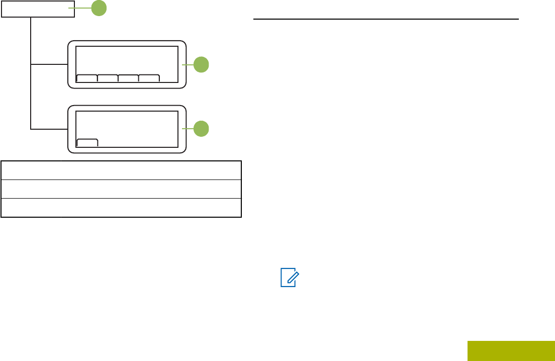
Z1
ZONE
CHAN
PWR SQL
REMOTE
F/R
A
B
C
A Transceiver
B Active Radio
C Non-Active Radio
You can change the command between the 2 control
heads by pressing the Menu Select button directly
below F/R, or the Menu Select button
preprogrammed user button on the keypad
microphone.
Contacts
This feature provides “address-book” capabilities on
your radio. Each entry corresponds to an alias (name)
or ID (number) that you use to initiate a call.
Contact entries are alphabetically sorted according to
entry alias. Each alias can have up to five IDs of
different call types associated with it.
Additionally, each entry, depending on context
(conventional, trunking, or phone), associates with
one or more of the four types of calls: Phone Call,
Selective Call, Private Call, or Call Alert.
Each entry within Contacts contains the following
information:
• Call Alias (Name)
• Call ID (Number)
• Call Type (Icon)
• WACN ID (Astro 25 Trunking IDs only)
• System ID
Note:
Your radio must be preprogrammed to allow
you to add, edit, or delete the contact entries.
Advanced Features
65
English
Draft
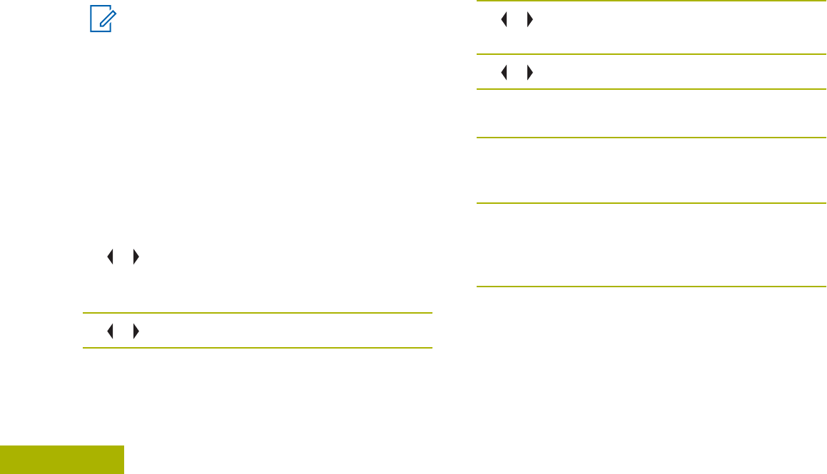
Your radio also supports a maximum of 50 call lists.
Each list can store up to 100 IDs (numbers).
Note:
Your radio is preprogrammed with a number of
contacts per Call Lists. Check with your dealer
or system administrator for more information.
The radio automatically exits the feature, if the
feature inactivity timer is enabled, when the
radio is left idle and the timer expires. You
hear the Menu Inactive Exit Tone upon feature
exit.
Making a Private Call from Contacts
Your radio must be preprogrammed to allow you to
use this feature.
1 or to CNTS and press the Menu Select button
directly below CNTS.
The entries are alphabetically sorted.
2 or to the required subscriber alias.
3Perform one of the following actions:
•Press the Menu Select button directly below
OPTN and proceed to the next step.
•Press the Menu Select button directly below
CNTS and proceed to step 6.
4 or to CALL and press the Menu Select button
directly below SEL.
5 or to select the call type.
6Hold the microphone vertically 1 to 2 inches (2.5 to
5.0 cm) from your mouth.
7Press the PTT button to initiate the call.
During the call, the display shows the subscriber
alias.
8Press and hold the PTT button to talk. Release the
PTT button to listen.
The LED lights up solid red when the PTT button
is pressed.
If there is no voice activity for a preprogrammed
period of time, the call ends.
If the call reaches the maximum ring time, the call
ends.
Advanced Features
66
English
Draft
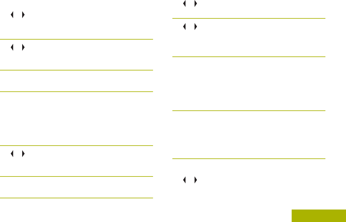
Adding a New Contact Entry
1 or to CNTS and press the Menu Select button
directly below CNTS.
The entries are alphabetically sorted.
2 or to [NEW CONTACT] and press the Menu
Select button directly below SEL.
The display shows NAME.
3Press the Menu Select button directly below
EDIT.
4Use the keypad to enter the name and press the
Menu Select button directly below OK once you
have entered the name.
To cancel this operation, press the Menu Select
button directly below CNCL to return to the previous
screen.
5 or to [ADD NUMBER] and press the Menu
Select button directly below SEL.
The display shows TYPE 1 <DEFAULT TYPE>.
6Press the Menu Select button directly below
EDIT.
7 or to the required channel and press the Menu
Select button directly below OK.
8 or to NUMBER 1 and press the Menu Select
button directly below EDIT.
The display shows NUMBER 1 and a blinking cursor
appears.
9Use the keypad to enter the number and press
the Menu Select button directly below OK once
you have entered the number.
To cancel this operation, press the Menu Select
button directly below CNCL to return to the previous
screen.
10 Press the Menu Select button directly below DONE
once you have finished.
The display shows <ENTRY> STORED, confirming
that the contact entry has been added.
The radio returns to the main Contacts screen.
Deleting a Contact Entry
1 or to CNTS and press the Menu Select button
directly below CNTS.
Advanced Features
67
English
Draft
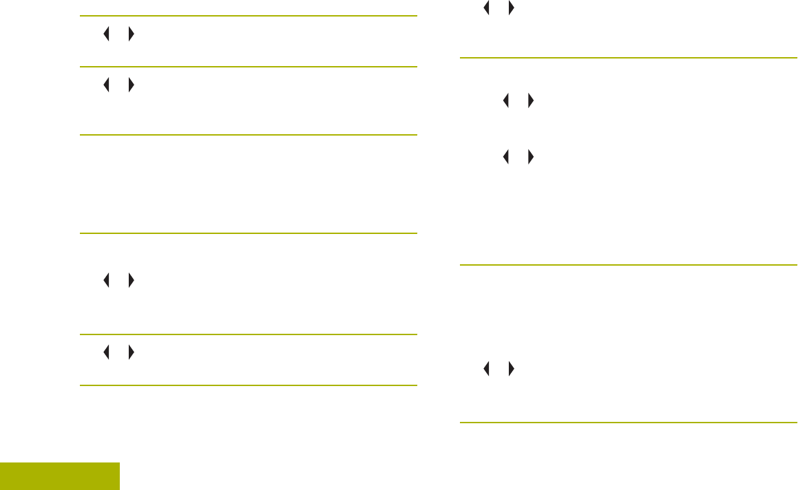
The entries are alphabetically sorted.
2 or to the entry you want to delete and press the
Menu Select button directly below OPTN.
3 or to DEL and press the Menu Select button
directly below SEL.
The display shows <ENTRY> CONFIRM DEL?.
4Select the Menu Select button directly below YES
to delete the entry, or NO to cancel and return to
the main screen of Contacts.
The display shows <ENTRY> DELETED and the
radio returns to the main screen of Contacts.
Adding a Contact to a Call List
1 or to CNTS and press the Menu Select button
directly below CNTS.
The entries are alphabetically sorted.
2 or to the entry you want to add and press the
Menu Select button directly below OPTN.
3 or to ADD TO CALLLST or ADD TO PHONLST
and press the Menu Select button directly below
SEL.
4Perform one of the following actions:
• or until the display shows [AVAILABLE] and
press the Menu Select button directly below
ADD to add as a new entry.
• or until the display shows <ENTRY> and its
associated number and press the Menu Select
button directly below RPLC to replace the
existing entry.
The display shows <ENTRY> ADDED, confirming
the addition of the contact to the list.
The radio returns to the main display of Contacts.
Methods of Contact Editing in a Call List
Editing an Entry Alias
1 or to CNTS and press the Menu Select button
directly below CNTS.
The entries are alphabetically sorted.
Advanced Features
68
English
Draft
2 or to the entry you want to edit and press the
Menu Select button directly below OPTN.
3 or to EDIT and press the Menu Select button
directly below SEL.
4 or to the entry alias you wish to change and
press the Menu Select button directly below EDIT.
A blinking cursor appears.
5Use the keypad to edit the name and press the
Menu Select button directly below OK once you
have finished.
The display returns to the Edit Contact screen.
6Press the Menu Select button directly below DONE
to save your changes and return to the main
screen of Contacts.
Editing as Entry ID
1 or to CNTS and press the Menu Select button
directly below CNTS.
The entries are alphabetically sorted.
2 or to the entry you want to edit and press the
Menu Select button directly below OPTN.
3 or to EDIT and press the Menu Select button
directly below SEL.
4 or to the entry ID you wish to change and press
the Menu Select button directly below EDIT.
A blinking cursor appears.
5Use the keypad to edit the number and press the
Menu Select button directly below OK once you
have finished.
The display returns to the Edit Contact screen.
6Press the Menu Select button directly below DONE
to save your changes and return to the main
screen of Contacts.
Editing a Call Type
1 or to CNTS and press the Menu Select button
directly below CNTS.
The entries are alphabetically sorted.
Advanced Features
69
English
Draft
2 or to the entry you want to edit and press the
Menu Select button directly below OPTN.
3 or to EDIT and press the Menu Select button
directly below SEL.
4 or to TYPE and press the Menu Select button
directly below EDIT.
5 or to choose from the list of call types given and
press the Menu Select button directly below OK.
The display returns to the Edit Contact screen.
6Press the Menu Select button directly below DONE
to save your changes and return to the main
screen of Contacts.
Scan Lists
Scan lists are created and assigned to individual
channels/ groups. Your radio scans for voice activity
by cycling through the channel/group sequence
specified in the scan list for the current channel/
group.
Your radio supports different types of Scan Lists:
• Trunking Priority Monitor Scan List
• Conventional Scan List
• Talkgroup Scan List
A maximum of 200 Scan Lists can be programmed in
your radio. These lists must be preprogrammed by a
qualified radio technician.
Viewing a Scan List
1 or to SCNL and press the Menu Select button
directly below SCNL.
2 or to view the members on the list.
3Press to exit the current display and return to
the Home screen.
Editing the Scan List
This feature lets you change scan list members and
priorities.
1 or to SCNL and press the Menu Select button
directly below SCNL.
The display shows the lists that can be changed.
Advanced Features
70
English
Draft
2 or to the entry you want to edit.
3Perform one of the following actions:
•Press the Menu Select button directly below
SEL to add and/or change the priority of the
currently displayed channel in the scan list.
•Press the Menu Select button directly below
DEL to delete the currently displayed channel
from the scan list.
•Press the Menu Select button directly below
RCL to view the next member of the scan list.
4Perform one of the following actions to select
another channel that needs to be added or deleted
then repeat step 3. Otherwise, proceed to the next
step.
• or to the desired channel.
• Use the keypad to enter the desired channel
name.
•Use the Mode Knob to select the channel.
5Press to exit scan list programming and return
to the Home screen.
See Viewing and Changing the Priority Status on
page 72 for more information on how to add and/or
change the priority of the currently displayed channel
in the scan list.
Changing the Scan List Status
1Long press the preprogrammed Scan side button.
2 or to the member you want to edit.
3Perform one of the following actions:
•Press the Select button once to add the
currently displayed channel to the scan list.
•Press the Select button one or more times to
change the scan list status icon of the currently
displayed channel.
4Perform one of the following actions:
• or to select more list members whose scan
status you want to change.
•Use the Mode Knob to select another scan list
member.
5Press to exit scan list programming and return
to the Home screen.
Advanced Features
71
English
Draft

Viewing and Changing the Priority Status
Perform one of the following actions:
•Press the Menu Select button directly below
SEL one or more times to change the priority
status of the current displayed channel.
•Press the Select button one or more times to
toggle between different status of the Scan List
status icon of the current displayed channel.
The radio shows one of following priority status
icons and scenarios:
• A Scan icon indicates that the current channel
is in the scan list as a non-priority channel. The
LED lights up solid green.
• A Priority-Two Channel Scan icon indicates
that the current channel is in the scan list as
the Priority-Two channel. The LED blinks
green.
• A Priority-One Channel Scan icon indicates
that the current channel is in the scan list as
the Priority-One channel. The LED rapidly
blinks green. You hear all traffic on the Priority-
One channel, regardless of traffic on non-
priority channels.
• No icon indicates that the current channel is
deleted from the scan list.
Scan
This feature allows you to monitor traffic on different
channels by scanning a preprogrammed list of
channels.
Turning Scan On or Off
Perform one of the following actions:
•Press the preprogrammed Scan button to
initiate or stop scan.
• or to SCAN and press the Menu Select
button directly below SCAN.
If the scan is enabled, the display shows SCAN ON
and the scan status icon.
If the scan is disabled, the display shows SCAN
OFF.
The radio returns to the Home screen.
Advanced Features
72
English
Draft

Turning Scan On While Disregarding the Squelch Code
(Conventional Channels Only)
You can still receive fleetwide, system-wide, dynamic
regrouping, incoming telephone interconnect and
Private Conversation/Call Alert calls while scanning
for activity.
You may respond to these types of calls as you would
normally on the selected channel. However, when
scanning different channels while in talkgroup scan,
incoming Private Conversation/Call Alert calls may be
missed.
or to MON and press the Menu Select button
directly below MON.
The brief MONITOR ON display indicates that the radio
is disregarding the squelch code.
Transmitting While the Scan is On
Transmitting Using Radio Programmed for
Talkback Scan
Press the PTT button to transmit on the channel
indicated by the display.
The radio does not begin scanning again for a
predetermined hang time after you release the
PTT button, allowing the other party to respond. If
the other party responds within the hang time,
scanning does not resume until the full hang time
expires after they have finished speaking, allowing
the conversation to be completed.
To transmit on the selected channel if another
channel is active, first turn scan off by pressing the
Menu Select button below SCAN momentarily.
Transmitting Using Radio Programmed for Non-
Talkback Scan
Press the PTT button at any time to transmit on
the selected channel or fixed channel.
To make a Call Alert page, or Private
Conversation call while scanning, press either the
Menu Select button directly below PAGE or CALL.
The call is entered on the selected channel and
scanning is halted until the call is exited by
pressing or pressing the Menu Select button
below either PAGE or CALL.
Deleting a Nuisance Channel
If a channel continually generates unwanted calls or
noise (termed a “nuisance” channel), you can
Advanced Features
73
English
Draft

temporarily remove the unwanted channel from the
scan list.
This capability does not apply to priority channels or
the designated transmit channel.
When the radio is locked onto the channel to be
deleted, or to NUIS and press the Menu Select
button directly below NUIS.
The radio continues scanning the remaining channels
in the list.
Restoring a Nuisance Channel
To restore the deleted nuisance channel, perform
one of the following actions:
• Stop and restart a scan.
• Mode change to another channel and back to
the original channel.
• Turn off the radio and then turn it on again.
Nuisance mode delete can be disabled by the
system administrator.
Changing Priorities Status While Scan is On
While the radio is scanning, the dynamic priority
change feature allows you to temporarily change any
channel in a scan list (except for the Priority-One
channel) to the Priority-Two channel.
This change remains in effect until scan is turned off.
Scan then reverts to the preprogrammed (original)
setting.
1Press the Menu Select button directly below DYNP
to change the priority of a non-priority channel in
the scan list to Priority-Two.
2Press momentarily to exit the scan list and
resume scanning.
Restoring Priorities in a Scan List
To restore the original channel priorities in a scan
list, perform one of the following actions:
• Turn scan off, and then on.
• Change channels.
• Turn off the radio, and then turn it back on.
Advanced Features
74
English
Draft

Using the Hang Up Box (HUB)
To temporarily suspend Scan Mode operation,
remove the control head from the Hang Up Box
(HUB).
You are allowed to use the control head while
scan is suspended. However, Priority Member
scanning is not suspended. This feature applies to
all Scan Lists and Scan Types. Scan is resumed
once the control head is returned to the holding
clip and the preprogrammed hang time has
elapsed.
Note:
Priority Scan List members are
continuously scanned only when the Scan
List, Designated Tx Member field is set to
“Talkback” in the radio programming.
Otherwise, all scan mode operation is
suspended.
Call Alert Paging
This feature allows your radio to work like a pager.
Even if other users are away from their radios, or if
they are unable to hear their radios, you can send
them an individual Call Alert page. You can also verify
if a radio is active on the system.
Depending on how your radio is programmed, when
you make an Enhanced Private Call, the radio either
automatically sends a call alert page if there is no
answer after the maximum ring time, or when you
press the PTT button.
Note:
This feature must be preprogrammed by a
qualified radio technician.
Receiving a Call Alert Page
When you receive a Call Alert page, you hear four
repeating alert tones and the LED blinks green. If Call
Alert Tone Auto Reset is enabled, you hear one alert
tone and the LED blinks green. The call received
icons blinks and the display shows PAGE RECEIVED.
Press the PTT button to answer or press any
button to clear the Call Alert page.
See Making a Talkgroup Call on page 51 or Making a
Private Call (Trunking Only) on page 52 for more
information on returning the call.
Advanced Features
75
English
Draft

Sending a Call Alert Page
The following methods are options on how to send a
call alert page. The result of all the methods is the
same. You can use the options interchangeably
depending on your preference and the programmed
functions.
Note:
If the feature inactivity timer is enabled, your
radio automatically exits the feature when your
radio is left idle long enough for the time to
expire. You hear the Menu Inactive Exit Tone
upon feature exit.
•Sending a call alert page via the preprogrammed
Quick Access (One-Touch) Call Alert Paging
button:
a) Press the preprogrammed Quick Access
(One-Touch) Call Alert Paging button to send
a page to the preprogrammed ID.
The display shows PAGING...<NUMBER> or
<ALIAS>.
If the call alert page is sent successfully, you
hear four high-pitched tones and the display
shows ACK RECEIVED. The radio returns to the
Home screen.
If the call alert page is not acknowledged, you
hear a low tone and the display shows NO
ACKNOWLEDGE. Press the Menu Select button
directly below OK to return to the main screen
for Contacts.
•Sending a call alert page via the radio menu PAGE:
a) or to PAGE.
b) Press the Menu Select button directly below
PAGE.
c) or to select the required ID.
d) Press the PTT button to send the page.
The display shows PAGING...<NUMBER> or
<ALIAS>.
If the call alert page is sent successfully, you
hear four high-pitched tones and the display
shows ACK RECEIVED. The radio returns to the
Home screen.
If the call alert page is not acknowledged, you
hear a low tone and the display shows NO
ACKNOWLEDGE. Press the Menu Select button
Advanced Features
76
English
Draft

directly below OK to return to the main screen of
Contacts.
•Sending a call alert page via the radio menu CALL:
a) or to CALL.
b) Press the Menu Select button directly below
CALL.
c) or to select the alias or ID, and press the
PTT button to initiate the call.
If the target radio does not respond after a
preprogrammed period of time, the display
shows SEND PAGE?.
d) To send the call alert page, press the Menu
Select button directly below YES. To exit the
screen without sending the call alert page,
press the Menu Select button directly below
NO.
The display shows PAGING...<ALIAS>.
If the call alert page is sent successfully, you
hear four high-pitched tones and the display
shows ACK RECEIVED. The radio returns to the
Home screen.
If the call alert page is not acknowledged, you
hear a low tone and the display shows NO
ACKNOWLEDGE. Press the Menu Select button
directly below OK to return to the main screen of
Contacts.
Enabling and Disabling In-Call User Alert
Make sure you are in Home mode where the default
zone and mode are being displayed.
You can enable and disable voice transmission, if
needed.
1 or to scroll to the VMUT and press the Menu
Select button directly below VMUT.
Voice mute is activated.
2To turn the feature off, press the Menu Select
button directly below VMUT or the VMut
preprogrammed button again.
Pressing the Menu Select button directly below
VMUT or the VMut programmed button momentarily
toggles between Voice mute on and Voice mute
off. VOICE MUTE ON shown on the display
indicates that the radio is muted to all conventional
dispatch calls and affiliated trunking group calls.
Advanced Features
77
English
Draft

Quick Call II (ASTRO P25 Digital Trunking and
Conventional)
This feature allows the user to broadcast a series of
distinct, recognizable tones before a voice
transmission from the dispatcher or a radio.
The broadcasting dispatcher or radio user can select
this alert tone transmission to be sent to an individual
Talkgroup or over the entire system. Specific tone or
series of tones are pre-programmed into the radios to
allow the dispatcher or supervisor to select a list of
tones to broadcast before they make their voice
transmission. Each tone is distinctive to indicate
different situation or different broadcaster. The
transmitting radio also plays back the tones for the
broadcaster to listen.
Note:
The receiving radios must be configured with
the Quick Call II tone in order for the radio to
sound the selected tone and also to sound a
preconfigured alert tone after the selected
tone has sound.
Initiating a Quick Call II Transmission
The broadcasting or transmitting radio must be pre-
programmed to see the tone in the Quick Call II tone
list. The receiving radio must also be pre-
programmed to decode the tone to broadcast.
1 or to QCII, and press the Menu Select button
directly below QCII.
2 or to select the tone to broadcast.
3Press the PTT to broadcast the selected tone, or
press and hold the PTT to broadcast the selected
tone and transmit with your vocal transmission.
You hear the radio sounds the selected tone. You
can begin your call after the tone ends.
4Release PTT to listen.
Emergency Operation
The Emergency feature is used to indicate a critical
situation.
Advanced Features
78
English
Draft

If the Orange button is preprogrammed to send an
emergency signal, this signal overrides any other
communication over the selected channel.
Your radio supports the following Emergency modes:
• Emergency Alarm
• Emergency Call (Trunking Only)
• Emergency Alarm with Emergency Call
• Silent Emergency Alarm
• Special Considerations for Emergencies
Check with your dealer or system administrator for
more information on the programming of this feature.
Only one of the Emergency modes above can be
assigned to the preprogrammed Emergency button
or the Emergency footswitch.
Note:
To exit emergency at any time, press and hold
the preprogrammed Emergency button for
about a second. This timer is programmable
from 0 – 6250 milliseconds by a qualified
technician.
Sending an Emergency Alarm
This feature allows you to send a data transmission,
which identifies the radio sending the emergency, to
the dispatcher.
1Press the preprogrammed Emergency button.
A tone sounds and the display alternates
EMERGENCY and the home display. A dispatcher
acknowledgment ACK RECEIVED display follows.
For trunking system, the radio also sounds a high-
pitched tone that indicates the alarm has been
received by the trunked system’s central
controller.
2Press and hold the EMERGENCY button or the
PTT button to return to normal operation.
Sending an Emergency Call (Trunking Only)
This feature gives your radio priority access to a
talkgroup.
1Press the preprogrammed Emergency button.
One of the following scenarios occurs:
• A tone sounds and the display alternates
EMERGENCY and the home display.
Advanced Features
79
English
Draft

• You hear the radio sounds a short low-pitched
tone to indicate the selected channel does not
support emergency and rejects to launch
emergency mode.
2Hold the microphone vertically 1 to 2 inches (2.0 to
2.5 cm) from your mouth.
3Press and hold the PTT button. Speak clearly into
the microphone.
4Release the PTT button to end the transmission
and wait for a response from the dispatcher.
5To exit Emergency Call, press and hold the
preprogrammed Emergency button for about a
second.
Sending an Emergency Alarm with Emergency Call
This feature gives your radio priority access on a
channel for conventional system, and to a talkgroup
for trunking system.
If the radio has both emergency call and alarm
features enabled, it automatically proceeds to the call
mode after the alarm is acknowledged.
1Press the preprogrammed Emergency button.
The display alternates EMERGENCY and the home
display. A high-pitched tone sounds, indicating
that the trunked system central controller has
received the alarm. A dispatcher acknowledgment
(four high-pitched tones) follows, accompanied by
an ACK RECEIVED display.
2Hold the radio vertically 1 to 2 inches (2.5 to 5.0
cm) from your mouth.
3Press and hold the PTT button. Speak clearly into
the microphone.
4Release the PTT button to end the transmission
and wait for a response from the dispatcher.
5To exit Emergency Call, press and hold the
preprogrammed Emergency button for about a
second.
Turning off the radio also cancels the emergency
state.
Sending a Silent Emergency Alarm
This feature allows you to send an Emergency Alarm
to the system without triggering any audio or visual
indicators.
Advanced Features
80
English
Draft

This activated microphone state is also known as “hot
mic”.
Note:
If you press the PTT button during hot mic,
and continue to press it after the hot mic
duration expires, the radio continues to
transmit until you release the PTT button.
1Press the preprogrammed Emergency button.
The display shows no changes, the LED does not
light up, and you hear no tones. The silent
emergency state continues until you perform the
next step.
2Press and hold the emergency button until a tone
sounds to exit the silent alarm mode.
If silent emergency alarm is used with emergency
call, pressing the PTT button exits the silent mode
and initiates the emergency call.
Special Considerations for Emergencies
• If you press the emergency button while in a
channel that has no emergency capability, a low-
pitched tone sounds.
• If the unit is out of the range of the system and/or
the emergency alarm is not acknowledged, a tone
sounds and the display shows NO ACKNOWLEDGE.
• If you press the emergency button, then change to
a mode that has no emergency capability, the
display shows NO EMERGENCY and a continuous
low-pitched tone sounds until a valid emergency
mode is selected or until the emergency is
cancelled.
• When an emergency is active, changing to
another mode where emergency is enabled
(trunked or conventional) causes an emergency
alarm and/or emergency call to be active on the
new mode.
Automatic Registration Service (ARS)
This feature provides an automated data application
registration for the radio. When you turn on the radio,
the device automatically registers with the server.
Data applications within the fixed network can
determine the presence of a device on the system
and send data to the device. For example: Text
Messaging Service (TMS).
Advanced Features
81
English
Draft

The Automatic Registration Service for the radio
consists of two (2) modes:
• ARS Server Mode (default mode)
• ARS Non-Server Mode
Note:
The default ARS mode can be changed by a
qualified radio technician using the radio’s
programming software.
Selecting or Changing the ARS Mode
The following methods are options on how to select or
change the ARS Mode. The result of all the methods
is the same. You can use the options interchangeably
depending on your preference and the programmed
functions.
•Selecting or Changing the ARS mode via the radio
menu:
a) Press and hold or to CHAN.
b) Press the Menu Select button directly below
CHAN.
The display shows the current zone is not
blinking, and the channel is blinking.
c) or or press the Mode Knob once and rotate
the Mode Knob to the desired channel.
One of the following scenarios occur:
• In ARS Server Mode, the display shows the
User Login Indicator icon, the zone, and
ARS server channel.
• In ARS Non-Server Mode, the display
shows the User Login Indicator icon, the
zone, and ARS non-server channel.
• If the channel or mode selected is
unprogrammed, the display shows
UNPROGRAMMED. Repeat this step.
d) Press to confirm the displayed zone and
channel.
•Selecting the ARS mode via the Mode Knob:
a) After the zone you want is displayed, toggle
until the display shows the required channel.
The display shows the current zone is not
blinking, and the channel is blinking.
b) or or press the Mode Knob once and rotate
the Mode Knob to the desired channel.
One of the following scenarios occur:
• In ARS Server Mode, the display shows the
User Login Indicator icon, the zone, and
ARS server channel.
Advanced Features
82
English
Draft

• In ARS Non-Server Mode, the display
shows the User Login Indicator icon, the
zone, and ARS non-server channel.
• If the channel or mode selected is
unprogrammed, the display shows
UNPROGRAMMED. Repeat this step.
c) Press to confirm the displayed zone and
channel.
User Login Feature
This feature allows you as the user to be associated
with the radio. With this association, every data
application (Example: Text Messaging Service) takes
on a friendly username.
You can still send text messages without logging in as
a user. The user login feature only enables the
recipient of your message to identify you as the
sender by assigning a username to your message.
Note:
Valid characters for a username entry are
capital letters (A – Z), small letters (a – z),
numbers (0 – 9), symbols (*, #, -, /), and the
space character.
The maximum length for a username is eight
(8) characters. Usernames are not case
sensitive in server mode but are case
sensitive in non-server mode.
A predefined username may sometimes be
invalid because the programming software
that is used to set predefined usernames
allows you to set usernames comprising of
eight (8) characters or more.
Logging In as a User
1 or to USER and press the Menu Select button
directly below USER.
The display shows the User Login screen.
2Perform one of the following actions:
• or to [ID Entry] and press the Menu
Select button directly below Edit to enter ID. A
blinking cursor appears on the screen. Use the
keypad to type or edit a user name. Press the
Menu Select button directly below Ok to
submit.
• or to scroll through the list of predefined
user names. Press the Menu Select button
Advanced Features
83
English
Draft

directly below SEL to select the predefined user
name.
•Press and hold or to scroll through the list of
predefined user names at a fast scroll rate.
Press the Menu Select button directly below
LOGN to select the predefined user name.
If the selected predefined username has more
than eight (8) characters, or an invalid character in
it, the display momentary shows INVALID ID.
3Press the Menu Select button directly below PIN.
A blinking cursor appears beside PIN.
4Enter your Personal Identification Number (PIN)
number.
The maximum PIN length is 4 digits. The PIN
number will appear as asterisks.
5Press the Menu Select button directly below
LOGN.
One of the following scenarios occurs:
• In ARS Server Mode, the display shows the
User Login Indicator icon, the ID, and IN
PROGRESS, with CNCL.
• In ARS Non-Server Mode, the display shows
the User Login Indicator icon, the ID, and
LOGGED IN, with LOGT and EXIT.
• In non-ARS enabled mode, the display shows
OFFLINE, with LOGT and EXIT.
One of the following scenarios occurs:
• If the user name is invalid, login fails and the user
login failure indicator (IP indicator) icon blinks. The
display also shows momentary LOGIN FAILED.
• If the PIN is invalid, login fails and the user login
failure indicator (IP indicator) icon blinks. The
display also shows momentary LOGIN FAILED.
• Wait for the logged in confirmation screen. If the
login process is successful, the display shows the
successful user login indicator (IP indicator) icon
and LOGGED IN, with LOGT and EXIT.
Note:
To cancel the login process and return to the
initial user login screen, press the Menu
Select button directly below CNCL.
Logging Out
Once the data application registration is completed,
you can log out.
Advanced Features
84
English
Draft
Note:
Private data refers to all messages in the text
messaging Inbox, Draft, and Sent folder. The
next user is able to access the Inbox, Draft
and Sent messages if private data is not
deleted.
1 or to LOGT and press the Menu Select button
directly below LOGT.
The display shows the User Login Indicator icon
and CLEAR PRIVATE DATA?.
2Perform one of the following actions:
• Select YES to clear all your private data. The
display shows momentary PRIVATE DATA
CLEARED.
• Select NO to keep your private data.
Text Messaging Service (TMS)
This features allows you to quickly send and receive
messages and run database queries directly from
your radios. The maximum length of characters for a
text message is 200.
The types of text messages available:
• A new text message (free form message).
• A predefined message (quick text message).
• An edited quick text message.
The main menu consists of the following options:
• Inbox
• Compose
• Drafts
• Sent
Note:
See Status Icons on page 35 for more
information on the TMS icons and TMS Menu
Options on page 39 for more information on
each menu option.
Accessing the Messaging Features
1Perform one of the following actions:
•Press the Data Feature button or the
preprogrammed TMS Feature button to access
the TMS feature screen.
•Press and hold the Data Feature button or the
preprogrammed TMS Feature button to access
the Inbox.
Advanced Features
85
English
Draft
• Follow the procedure described next to access
this feature via the radio menu.
2 or to TMS.
3Press the Menu Select button directly below TMS
to access the TMS feature screen.
4 or to scroll through the main menu options.
Note:
The radio automatically exits the feature, if
the feature inactivity timer is enabled, when
the radio is left idle and the timer expires.
You will hear the Menu Inactive Exit Tone
upon feature exit.
Press the Menu Select button directly
below Back at any time to return to the
previous screen.
Composing and Sending a New Text Message
During the uppercase and lowercase mode, multi-
tapping the keys only scrolls through the letters. For
example, A->B->C, a->b->c.
During the numeric mode, except for , pressing
the keypad only enters the numeric digits.
Subsequent presses of the same key inserts the
same digit to the text message (no multi-tap).
1 or to TMS.
2Press the Menu Select button directly below TMS
to access the TMS feature screen.
3Press the Menu Select button directly below COMP
to see the compose options.
4Press the Menu Select button directly below NEW
to compose a new message.
A blinking cursor appears on the COMPOSE screen.
5Use the keypad to type or edit your message.
6Press the Menu Select button directly below OPTN
once the message is composed.
7Perform one of the following actions:
• or to scroll through the address list and
select the required address.
Advanced Features
86
English
Draft

• or to [OTHER RECPNT] and press the Menu
Select button below EDIT. When a blinking
cursor appears in the ENTER ADDRESS screen,
use the keypad to type the address entry.
8Press the Menu Select button directly below SEND
or press the PTT button to send the message.
The display shows the SEND MESSAGE screen and
SENDING MSG.
If the message is sent, you hear a tone and the
display shows MSG SENT.
If the message is not sent, you hear a low tone,
the display shows SEND FAILED and returns to the
main TMS screen.
Note:
You can append a priority status and/or a
request reply to your message. See Priority
Status and Request Reply of a New Text
Message on page 88 for more
information.
You can also select the DRFT option to
save your message in the Drafts folder to
send it at a later time. See Accessing the
Drafts Folder on page 93 for more
information.
Sending a Quick Text Message
Quick Text messages are messages that are
predefined and usually consist of messages that are
used most frequently.
Each Quick Text message has a maximum length of
50 characters.
1Perform one of the following actions:
• To access this feature via a preprogrammed
button, press the preprogrammed Quick Text
button and proceed to Step 4.
• To access this feature via the menu, proceed
to the next step.
2 or to TMS and press the Menu Select button
directly below TMS to access the TMS feature
screen.
3Perform one of the following actions:
•Press the Menu Select button directly below
COMP to see the compose options.
Advanced Features
87
English
Draft

•Press the Menu Select button directly below
EXIT to return to the Home screen.
4Press the Menu Select button directly below LIST
to see the quick text list.
5 or to scroll through the list of messages and
press the Menu Select button directly below SEL
to select the required message.
The message appears on the COMPOSE screen,
with a blinking cursor at the end of it. Use the
keypad to edit the message, if required.
6Press the Menu Select button directly below
OPTN.
7Press the Menu Select button directly below
SEND.
8Perform one of the following actions:
• or to scroll through the address list and
select the required address.
• or to [OTHER RECPNT] and press the Menu
Select button below EDIT. When a blinking
cursor appears on the ENTER ADDRESS screen.
Use the keypad to type the address entry.
9Press the Menu Select button directly below SEND
or press the PTT button to send the message.
The display shows the SEND MESSAGE screen and
SENDING MSG.
If the message is sent, you hear a tone and the
display shows MSG SENT.
If the message is not sent, you hear a low tone,
the display shows SEND FAILED and returns to the
main TMS screen.
Note:
You can append a priority status and/or a
request reply to your message. See Priority
Status and Request Reply of a New Text
Message on page 88 for more
information.
Priority Status and Request Reply of a New Text
Message
Before sending your message, you can append a
priority status and/or a request reply to your message.
Advanced Features
88
English
Draft

Appending a Priority Status to a Text Message
Ensure that an outgoing message is composed to
allow you to perform this procedure. See Composing
and Sending a New Text Message on page 86 for
more information.
Note:
The Priority Status icon on a message does
not imply that the message gets higher priority
over the other messages when it is being
transmitted. It is just an indication that can be
embedded into a message to let the receiver
know that the message is important.
1Press the Menu Select button directly below
OPTN.
2Press the Menu Select button directly below IMPT
to indicate the message as important.
The priority status icon appears beside the normal
message icon on the label bar.
Removing a Priority Status from a Text Message
Ensure there is an outgoing message composed to
allow you to perform this procedure. See Composing
and Sending a New Text Message on page 86 for
more information.
1Press the Menu Select button directly below
OPTN.
2Press the Menu Select button directly below IMPT
to remove the priority status icon.
The display shows the normal message icon on the
label bar.
Appending a Request Reply to a Text Message
Ensure that an outgoing message is composed to
allow you to perform this procedure. See Composing
and Sending a New Text Message on page 86 for
more information
1Press the Menu Select button directly below
OPTN.
2Press the Menu Select button directly below RQRP
to request for a reply.
The request reply icon appears beside the normal
message icon on the label bar.
Advanced Features
89
English
Draft

Removing a Request Reply from a Text Message
Ensure that an outgoing message is composed to
allow you to perform this procedure. See Composing
and Sending a New Text Message on page 86 for
more information.
1Press the Menu Select button directly below
OPTN.
2Press the Menu Select button directly below RQRP
to remove the reply status icon.
The display shows the normal message icon on the
label bar.
Appending a Priority Status and a Reply Request
to a Text Message
Ensure that an outgoing message is composed to
allow you to perform this procedure. See Composing
and Sending a New Text Message on page 86 for
more information.
1Press the Menu Select button directly below
OPTN.
2Press the Menu Select button directly below IMPT
to indicate the message as important.
3Press the Menu Select button directly below RQRP
to request for a reply.
The priority status and request reply icons appear
beside the normal message icon on the label bar.
Removing a Priority Status and a Reply Request
from a Text Message
Ensure that a outgoing message is composed to
allow you to perform this procedure. See Composing
and Sending a New Text Message on page 86 for
more information.
1Press the Menu Select button directly below
OPTN.
2Press the Menu Select button directly below IMPT
to remove the priority status icon.
3Press the Menu Select button directly below RQRP
to remove the reply status icon.
The display shows the normal message icon on the
label bar.
Advanced Features
90
English
Draft
Receiving a Text Message
Note:
When you receive a message that is flagged
with the “Request Reply” icon, you must
manually respond to the sender that you have
received the message. The system will not
automatically send a notification to
acknowledge that the message was received.
The following methods are options on how to receive
a text message. The result of all the methods is the
same. You can use the options interchangeably
depending on your preference and the programmed
functions.
•Receiving a text message via the Data Feature
button or the TMS Feature button:
a) When you receive a message, press and hold
the preprogrammed Data Feature button or the
TMS Feature button to access the Inbox.
The display shows a list of aliases or IDs, with
the sender of the latest received message on
top.
•Receiving a text message via the radio menu:
a) When the new message icon appears and the
display shows momentary NEW MSG, press the
Menu Select button directly below TMS to
access the Inbox.
The display shows a list of aliases or IDs, with
the sender of the latest received message on
top.
Viewing a Text Message from the Inbox
The Inbox can hold up to thirty (30) messages.
Note:
or to read the message if the content fills
more than one screen.
1Perform one of the following actions:
•Press the preprogrammed Data Feature button
or the TMS Feature button to access the TMS
feature screen. Press the Menu Select button
directly below INBX.
•Press and hold the preprogrammed Data
Feature button or the TMS Feature button to
access the Inbox.
• or to TMS and press the Menu Select button
directly below TMS to access the TMS feature
Advanced Features
91
English
Draft
screen. Press the Menu Select button directly
below INBX.
The display shows the latest received message.
2While on the view message screen, press the
Menu Select button directly below RPLY, DEL, or
BACK to access the option.
• Select RPLY to reply the message.
• Select DEL to delete the message.
• Select BACK to return to the previous screen.
Note:
The icon at the top right corner of the
screen indicates the status of the message.
See Text Messaging Service (TMS)
Indicators on page 38 for more information.
Replying to a Received Text Message
Note:
The original date and time stamp, address and
message content is automatically appended to
the reply message.
1Press the Menu Select button directly below RPLY
to reply to a message.
2Perform one of the following actions:
•Press the Menu Select button directly below
NEW to compose a new message.
•Press the Menu Select button directly below
LIST to select a predefined message.
• or to scroll through the list of predefined
messages and press the Menu Select button
directly below SEL to select the required
message.
One of the following scenarios occurs:
• A blinking cursor appears on the Compose
screen.
• The predefined message appears on the
Compose screen, with a blinking cursor at the
end of it.
3Use the keypad to type or edit your message.
4Press the Menu Select button directly below OPTN
once you have completed the message.
5Press the Menu Select button directly below SEND
to send the message.
Advanced Features
92
English
Draft

The display shows the Send Message screen and
SENDING MSG.
Note:
Press the Menu Select button directly below
BACK at any time to return to the previous
screen.
You can append a priority status and/or a
request reply to your message. See Priority
Status and Request Reply of a New Text
Message on page 88 for more information.
Accessing the Drafts Folder
This folder stores the messages that were saved
previously. The Drafts folder can hold up to 10
messages. The oldest draft in the folder is deleted
when the 11th message comes in.
1 or to TMS.
2Press the Menu Select button directly below TMS
to access the TMS feature screen.
3Press the Menu Select button below DRFT.
The display shows the latest drafted text message.
4Press the Menu Select button directly below
EDIT, DEL, or BACK to access the option.
• Select EDIT to edit the message before
sending it.
• Select DEL to delete the message.
• Select BACK to return to the previous screen.
Sent Text Messages
Once a message is sent to another radio, it is saved
in the Sent folder. The most recent sent text message
is always added to the top of the Sent list.
The Sent folder is capable of storing a maximum of
ten (10) last sent messages. When the folder is full,
the oldest message in the folder is deleted when the
11th message comes in.
Viewing a Sent Text Message
1Perform one of the following actions:
•Press the preprogrammed Data Feature button
or the TMS Feature button to access the TMS
feature screen.
Advanced Features
93
English
Draft
• or to TMS and press the Menu Select button
directly below TMS to access the TMS feature
screen.
2Press the Menu Select button below SENT.
The display shows the latest sent message.
3While on the view message screen, press the
Menu Select button directly below OPTN, DEL or
BACK to access the option.
• Select OPTN to configure the message settings.
• Select DEL to delete the message.
• Select BACK to return to the previous screen.
Note:
The icon at the top right corner of the
screen indicates the status of the message.
See Text Messaging Service (TMS)
Indicators on page 38 for more information.
Sending a Sent Text Message
1Press the Menu Select button directly below OPTN
while viewing the message.
2Press the Menu Select button directly below
SEND.
3Perform one of the following actions:
• or to scroll through the address list and
select the required address.
• or to [OTHER RECPNT] and press the Menu
Select button below EDIT. When a blinking
cursor appears in the ENTER ADDRESS screen,
use the keypad to type the address entry.
4Press the Menu Select button below SEND or the
PTT button to send the message.
The display shows the SEND MESSAGE screen and
SENDING MSG.
Note:
Press the Menu Select button directly
below BACK at any time to return to the
previous screen.
You can append a priority status and/or a
request reply to your message. See Priority
Status and Request Reply of a New Text
Message on page 88 for more information.
Advanced Features
94
English
Draft
Deleting Text Messages
1From the Inbox, Draft, or Sent screen, or to
scroll through the messages.
2Press the Menu Select button directly below DEL
to view the delete options.
3Perform one of the following actions:
•Press the Menu Select button directly below
CURR to delete the current message.
•Press the Menu Select button directly below
ALL to delete all the messages.
Secure Operations
Secure radio operation provides the highest
commercially available level of voice security on both
trunked and conventional channels.
Unlike other forms of security, Motorola digital
encryption provides signaling that makes it virtually
impossible for others to decode any part of an
encrypted message.
Enabling Secure Transmission
1 or to SEC and press the Menu Select button
directly below SEC.
The display shows and the current key if multi-
key has been enabled.
2Monitor the mode to be sure it is not in use.
3Press PTT button to transmit.
Note:
If the selected channel is preprogrammed
for clear-only operation – when you press
the PTT button, an invalid mode tone
sounds and the display shows CLEAR TX
only.
The radio does not transmit until you
disable the secure mode.
The radio can be configured to ignore the
clear voice or unsecured transmission
when the radio is in secured transmission.
Check with your agent for details.
Advanced Features
95
English
Draft
Accessing the Secure Feature
1 or to SEC.
2Press and hold the Menu Select button directly
below SEC to display Secure feature screen.
The display shows the Secure screen.
Managing Encryption
Loading the Encryption Key(s)
Note:
Refer to the key-variable loader (KVL) manual
for equipment connections and setup.
1Attach the KVL to your radio.
The display shows KEYLOADING, and all other
radio functions are locked out, except for power
down, and volume.
2Press the Menu Select button below TARGET.
3Press the Menu Select button below LOAD.
4Perform one of the following actions:
•Press the Menu Select button below KEY for
single-key.
•Press the Menu Select button below GROUP for
multikey.
5 or to the required key or group.
6Press the Menu Select button below LOAD to load
the key to your radio.
When the key has been loaded successfully, one of
the following scenarios occurs:
• You hear a short tone for single-key radios.
• You hear an alternating tone for multikey radios.
Multikey Feature
This feature allows the radio to be equipped with
different encryption keys and supports the DES-OFB
algorithm.
There are two types:
Conventional
Multikey The encryption keys can be tied
(strapped), on a one-per-channel
basis, through Customer
Programming Software. In addition,
you can have operator-selectable
keys, operator-selectable keysets,
and operator-selectable key
Advanced Features
96
English
Draft
erasure. If talkgroups are enabled
in conventional, then the encryption
keys are strapped to the talkgroups.
Trunked
Multikey If the radio is used for both
conventional and trunked
applications, strap the encryption
keys for trunking on a per-talkgroup
or announcement-group basis. In
addition, a different key can be
strapped to other features, such as
dynamic regrouping, failsoft, or
emergency talkgroup. You can
have operator-selectable key
erasure.
Selecting an Encryption Key
1 or to KEY.
2Press the Menu Select button directly below KEY.
The display shows the last user-selected and
stored encryption key, and the available menu
selections.
3 or to scroll through the encryption keys or use
the keypad to enter the number of the desired key.
4Perform one of the following actions:
•Press the Menu Select button directly below
SEL to save the newly selected key and return
to the Home screen.
•Press , the PTT button, or the Menu Select
button directly below EXIT.
•Turn the 16-Position Select knob to exit.
Note:
When the selected key is erased, you hear
a momentary keyfail tone and the display
shows KEY FAIL.
When the selected key is not allowed, you
hear a momentary illegal key tone and the
display shows ILLEGAL KEY.
Selecting a Keyset
This feature allows you to select one or more groups
of several encryption keys from among the available
keys stored in the radio.
For example, you could have a group of three keys
structured to one keyset, and another group of three
different keys structured to another keyset; by
Advanced Features
97
English
Draft
changing keysets, you would automatically switch
from one set of keys to the other.
Every channel to which one of the original keys was
tied now has the equivalent new key instead.
1 or to KSET and press the Menu Select button
directly below KSET.
The display shows the last user-selected and
stored keyset, and the available keyset menu
selections.
2 or to scroll through the keysets or use the
keypad to enter the number of the desired keyset.
3Press the Menu Select button directly below SEL
to save the newly selected keyset.
The radio exits keyset selection and returns to the
Home screen.
Note:
Press , the PTT button, or the EXIT
menu selection to exit this menu at any
time without changing the keyset selection.
Erasing the Selected Encryption Keys
This feature allows you to erase all or selected
encryption keys.
Erasing the selected encryption keys via the radio
menu:
a) or to ERAS and press the Menu Select
button directly below ERAS.
The display shows the last user-selected and
stored encryption key, and the available menu
selections.
b) or to the desired encryption key or use the
keypad to enter the number of the desired key.
c) Press the Menu Select button directly below
ALL to delete all keys, or press the Menu
Select button directly below SNGL to delete
current shown key.
You can abort this screen and return to Home
screen by pressing the Menu Select button
directly below ABRT.
Requesting an Over-the-Air Rekey (ASTRO
Conventional Only)
Ensure that the Unique Shadow Key (USK) is loaded
into the radio with the key-variable loader (KVL)
Advanced Features
98
English
Draft
before the rekey request can be sent. Refer to your
local key management supervisor for more
information.
This feature, also known as OTAR, allows the
dispatcher to reprogram the encryption keys in the
radio remotely. The dispatcher performs the rekey
operation upon receiving a rekey request from the
user.
1 or to REKY.
2Press the Menu Select button directly below
REKY.
3Perform one of the following actions:
•Press the PTT button to send the rekey
request.
•Press the PTT button again, or the or
Emergency button, to exit the feature and
transmit in normal mode.
If the rekey operation fails, you hear a bad-key
tone and the display shows REKEY FAIL.
Note:
The rekey operation failure indicates that
your radio does not contain the Unique
Shadow Key (USK).
MDC Over-the-Air Rekeying (OTAR) Page
This feature allows you to view or define MDC Over-
the-Air Rekeying (OTAR) features. It is applied only
when operating in secure encrypted mode and only
for conventional communications. In additional to
Rekey Requests, OTAR transmissions include
Delayed Acknowledgements, and Power-up
Acknowledgements.
Some of the options selected may also need to be set
up at the Key Management Controller (KMC) site to
work properly.
Note:
This feature must be preprogrammed by a
qualified radio technician. Check with your
dealer or system administrator for more
information.
Infinite UKEK Retention
This feature enables Unique Key Encryption Key
(UKEK) to be permanently stored in the radio even
Advanced Features
99
English
Draft

when all of the encryption keys is erased. Without this
UKEK key, the radio cannot be rekeyed over the air.
Note:
This feature must be preprogrammed by a
qualified radio technician. Check with your
dealer or system administrator for more
information.
Hear Clear
Note:
This feature must be preprogrammed by a
qualified radio technician. Check with your
dealer or system administrator for more
information.
There are two components of Hear Clear.
Companding Reduces the channel noise, e.g.
OTA transmission, that is
predominantly present in UHF2 and
900 MHz channel with the following
features.
Compressor Reduces the
background noise
flow and the speech
signal at
transmitting radio.
Expander Expands the speech
while the noise flow
remains the same at
receiving radio.
Random FM
Noise
Canceller
(Flutter
Fighter)
Reduces the unwanted effects of
random FM noise pulses caused by
channel fading under high Signal-to-
Noise (S/N) conditions such as in a
moving transportation. The fading
effects, heard as audio pops and
clicks, are cancelled without
affecting the desired audio signal.
The Random FM Noise Canceller
operates only in receive mode.
Advanced Features
100
English
Draft

Global Positioning System / Global
Navigation Satellite System
Note:
This feature is addressed as GPS across the
manual as the naming convention of the
buttons and strings remain the same as the
legacy feature of GPS.
The availability and accuracy of this location
information (and the amount of time that it takes to
calculate it) varies depending on the environment in
which you are using the GPS feature.
For example, GPS location fixes are difficult to obtain
indoors, in covered locations, between high buildings,
or in situations where you have not established a
clear broad view of the sky.
GPS Operation
The GPS technology uses radio signals from earth
orbiting satellites to establish location coordinates.
Therefore, maximizing your view of unobstructed sky
is essential for optimum performance.
Where adequate signals from multiple satellites are
not available (usually because you cannot establish a
view of a wide area of the sky), the GPS feature of
your radio will not work. Such situations include but
are not limited to:
• Underground locations
• Inside buildings, trains, or covered vehicles
• Under any metal, or concrete roof, or structure
• Between tall buildings or under dense tree-cover
• In temperature extremes outside the operating
limits of your radio
Even where location information can be calculated in
such situations, it may take longer to do so, and your
location estimate may not be as accurate. Therefore,
in any emergency situation, always report your
location to your dispatcher.
Keep in mind that the accuracy of the location
information and the time it takes to obtain it varies
depending upon circumstances, particularly the ability
to receive signals from an adequate number of
satellites.
Note:
Even where adequate signals from multiple
satellites are available, your GPS feature only
provides an approximate location, usually
within 10 meters from your actual location, but
sometimes farther away.
Advanced Features
101
English
Draft

The satellites used by the GPS feature are controlled
by the U.S. government and are subject to changes
implemented in accordance with the Department of
Defense GPS user policy and the Federal Radio
Navigation Plan. These changes may affect the
performance of the GPS feature on your radio.
GPS Performance Enhancement
Sometimes, the GPS feature may be unable to
complete a location calculation successfully. You then
see a message indicating that your radio cannot
connect to enough visible satellites.
To maximize the ability of your radio to determine a
fix, take note of the following guidelines:
• For your initial fix, hold the radio in the face
position.
• Stay in the open. The GPS feature works best
where there is nothing between your radio and the
open sky.
The Outdoor Location Feature (Using GPS)
This feature allows you to determine your current
location using a location menu, as well as your
current distance and bearing in relation to another
location. Radio location may be requested and
reported over-the-air.
Your radio stores up to a maximum of sixty (60)
programmable location coordinates, also known as
waypoints. When the memory is full, the next
waypoints automatically replaces the oldest
waypoints in the radio.
The radio also stores four (4) preprogrammed
waypoints. These coordinates cannot be deleted.
The following table shows the differences between
programmable waypoints and preprogrammed
waypoints.
Programmable Way-
points Preprogrammed Way-
points
User-configurable loca-
tion coordinates. Fixed location coordi-
nates:
• Home
• Emergency
• Last Known Location
• Destination
Advanced Features
102
English
Draft
Programmable Way-
points Preprogrammed Way-
points
Only the alias is editable,
not the coordinates. The Home and Destina-
tion coordinates are edit-
able.
Coordinates can be de-
leted one at a time, or all
at once.
Coordinates cannot be
deleted.
Note:
The radio automatically exits the feature, if the
feature inactivity timer is enabled, when the
radio is left idle and the timer expires. You
hear the Menu Inactive Exit Tone upon feature
exit.
Accessing the Outdoor Location Feature
Note:
An ON radio menu may be present on the
Location menu screen if it is preprogrammed
by the dealer or system administrator.
1 or to LOC.
2Press the Menu Select button directly below LOC.
The display shows LOCATION OFF <LATITUDE>.
3Press the Menu Select button directly below On to
turn on the GPS.
The display shows PREVIOUS LOC <LATITUDE>.
4 or to check the longitude, time and date of the
last successful location fix.
5To obtain a new location fix, press the Menu
Select button directly below RFSH.
The top line temporarily displays PLEASE WAIT
while the new location is being determined. While
the new location is being determined, the location
signal can be a solid or blinking icon. The location
coordinates are updated automatically every 5
seconds while the location signal is present.
6To return to the Home screen, press , the PTT
button, or the Menu Select button directly below
EXIT.
Turning Off GPS
1 or to LOC.
2Press the Menu Select button directly below LOC.
Advanced Features
103
English
Draft
The display shows PREVIOUS LOC <LATITUDE>.
3 or to check the time and date of the last
successful location fix.
4Press the Menu Select button directly below
OPTN.
5 or to TURN OFF GPS (if preprogrammed).
6Press the Menu Select button directly below SEL
to turn off the GPS.
The display shows LOCATION OFF.
7To return to the Home screen, press , the PTT
button, or the Menu Select button directly below
EXIT.
Saving a Waypoint
Ensure that your radio shows the current location on
the screen.
1Press the Menu Select button directly below
OPTN.
2Perform one of the following actions:
• or to SAVE AS WAYPT and press the Menu
Select button directly below SEL.
• or to SAVE AS HOME and press the Menu
Select button directly below SEL and proceed
to step 5.
• or to SAVE AS DEST. and press the Menu
Select button directly below SEL and proceed
to step 5.
A blinking cursor appears in the screen.
3Use the keypad to edit the auto-generated
waypoint, if required, or press the Menu Select
button directly below CNCL to return to the Location
main screen.
4Press the Menu Select button directly below OK
once you are done.
One of the following scenarios occur:
• The display shows SAVED AS <WAYPOINT
NAME>.
• The display shows SAVED AS HOME.
• The display shows SAVED AS DEST..
Advanced Features
104
English
Draft
5To return to the Home screen, press , the PTT
button, the preprogrammed GPS button or the
Menu Select button directly below EXIT.
Viewing a Saved Waypoint
Ensure your radio shows the current location on the
screen.
1Press the Menu Select button directly below
OPTN.
2 or to WAYPOINTS and press the Menu Select
button directly below SEL.
The display shows a list of waypoints.
3Perform one of the following actions:
• or to scroll through the list.
• or to select a waypoint to view the location
information in full.
4Press the Menu Select button directly below
OPTN.
5To view the longitude, time and date of the
selected waypoint, or to VIEW and press the
Menu Select button directly below SEL.
6To return to the previous screen, press the Menu
Select button directly below BACK, or to return to
the Home screen, press or the PTT button.
Editing the Alias of a Waypoint
Ensure your radio shows the current location on the
screen.
1Press the Menu Select button directly below
OPTN.
2 or to WAYPOINTS and press the Menu Select
button directly below SEL.
The display shows a list of waypoints.
3 or to the required saved waypoint, and press
the Menu Select button directly below OPTN.
4 or to EDIT NAME and press the Menu Select
button directly below SEL.
Advanced Features
105
English
Draft
A blinking cursor appears in the EDIT NAME
screen.
5Use the keypad to edit the alias.
6Perform one of the following actions:
•Press the Menu Select button directly below
OK once you are done.
•Press the Menu Select button directly below
CNCL to return to the Waypoints main screen.
7The display shows <WAYPOINT NAME> UPDATED
and the radio returns to the Waypoints main
screen.
8Perform one of the following actions:
•Press the Menu Select button directly below
BACK to return to the previous screen.
•Press or the PTT button to return to the
Home screen.
Editing the Coordinates of a Waypoint
Note:
Only the preprogrammed coordinates of Home
and Destination can be edited by the user.
Ensure your radio shows the current location on the
screen.
1Press the Menu Select button directly below
OPTN.
2 or to WAYPOINTS and press the Menu Select
button directly below SEL.
The display shows a list of waypoints.
3Perform one of the following actions:
•or to [HOME] and press the Menu Select
button directly below OPTN.
•or to [DESTINATION] and press the Menu
Select button directly below OPTN.
4 or to EDIT LOCATION and press the Menu
Select button directly below SEL.
The first number blinks.
5Utilize the following control buttons to select the
number/coordinates if required, then press the
Menu Select button directly below EDIT to change
the number/coordinates.
Advanced Features
106
English
Draft

•Press to move to the previous number/
coordinates.
•Press to move to the next number/
coordinates.
• Press or to change the North (N), South
(S), East (E) or West (W) direction.
A blinking cursor appears in the EDIT LOCATION
screen.
6Utilize the following control buttons or menu to
change the number/coordinates if required then
press the Menu Select button directly below OK
once.
•Press to move one space to the left.
•Press to move one space to the right.
•Press the Menu Select button directly below
DEL to delete any unwanted characters.
•Press the Menu Select button directly below
CNCL to return to the previous screen
7Press the Menu Select button directly below OK
once complete setting up the new Home or
Destination.
One of the following scenarios occurs:
• The display shows [HOME] UPDATED and the
radio returns to the Waypoints main screen.
• The display shows [DESTINATION] UPDATED
and the radio returns to the Waypoints main
screen.
Deleting a Single Saved Waypoint
Ensure your radio shows the current location on the
screen.
1Press the Menu Select button directly below
OPTN.
2 or to WAYPOINTS and press the Menu Select
button directly below SEL.
The display shows a list of waypoints.
3Perform one of the following actions:
• or to the required saved waypoint, and
press the Menu Select OPTN. or to Edit
name and press the Menu Select button
directly below Del.
•Press the Menu Select button directly below
Del.
Advanced Features
107
English
Draft
4The display shows <WAYPOINT NAME> CONFIRM
DEL?.
5Press the Menu Select button directly below YES
to delete the waypoint or press the Menu Select
button directly below NO to return to the Waypoints
main screen.
The display shows <WAYPOINT NAME> DELETED .
Deleting All Saved Waypoints
Ensure your radio shows the current location on the
screen.
Note:
You cannot delete any of the preprogrammed
waypoints.
1Press the Menu Select button directly below
OPTN.
2 or to WAYPOINTS and press the Menu Select
button directly below SEL.
The display shows a list of waypoints.
3 or to the required saved waypoint, and press
the Menu Select button directly below OPTN.
4 or to DELETE ALL and press the Menu Select
button directly below SEL.
The display shows ALL SAVED WAYP CONFIRM
DEL?.
5Press the Menu Select button directly below YES
to delete all waypoints or press the Menu Select
button directly below NO to return to the Waypoints
main screen.
The display shows ALL SAVED WAYP DELETED.
Measuring the Distance and Bearing from a Saved
Waypoint
Ensure your radio shows the current location on the
screen.
1Press the Menu Select button directly below
OPTN.
2 or to DIST FRM HERE and press the Menu
Select button directly below SEL.
The display shows a list of waypoints.
3 or to the required waypoint and press the Menu
Select button directly below SEL.
Advanced Features
108
English
Draft

The display shows the distance and bearing from the
current to the selected coordinates.
Location Feature in Emergency Mode
When the Emergency feature is activated by pressing
the emergency button, the radio exits the Location
menu and returns to the Home (default) screen so
that you can see which channel the emergency signal
is going out on.
However, you may re-enter the Location menu while
still in emergency mode, provided that Silent
Emergency has not been activated.
If you have turned Location off using the ON/OFF
menu key, it automatically turns back on when
Emergency is activated.
If there is a solid location signal during Emergency,
the current location and the location information
received is saved as Emergency and Last Known
Location waypoints, respectively.
Peer-Location on the Display (ASTRO Conventional
only)
This feature is only available for radio-to-radio voice
transmissions, dispatch call and selective call in
conventional ASTRO system. For radio-to-radio
transmission, in order to allow the radio to show peer-
location, the voice should be directly sent from one
radio to another radio without passing through any
infrastructure facility such as repeaters, phone or
DVRS system. Both the transmitting radio and
receiving radio must be configured to enable them to
send and/or receive the GPS coordinates. You can
check with your nearest qualified technician for more
details.
Note:
If the receiving radio is operating in a Mixed
Mode channel, and the voice transmission is
via conventional ASTRO system then the
radio can receive the location coordinates of
its peers.
This feature is also operable in a Scan Active channel
or Scan Talkback channel.
Upon receiving a voice transmission with GPS
coordinates enabled on the receiving radio, the
display shows the coordinates available in full or in
short coordinates. There are two different formats
available. Refer to the following list for the details
shown in the Peer-Location quick text. Consult your
agent to pick the best format to configure to your
radio.
Advanced Features
109
English
Draft

Full location
coordinates • PTT ID (This is optional.)
• Longitude and latitude
• Relative distance or
direction.
Short location
coordinates • PTT ID (This is optional.)
• Longitude and latitude
Note:
If the transmitting radio is stale at its location
after a period of time, the receiving radio
display shows LAST KNWN LOC:
<Coordinates> <distance> on top of
ID:<PTT ID>. The PTT ID seen here is
optional to be shown on the display per
requirement of usage.
If the transmitting radio does not have GPS or
the receiving radio could not decode the GPS
signal of the received signal, the receiving
radio display shows UNKNOWN LOC on top of
ID:<PTT ID>. If the radio is not configured to
show PTT ID, you see only UNKNOWN LOC.
Geofence (ASTRO 25 Trunking System)
Geofence is a virtual perimeter based on the GPS to
define a geographical area on earth.
Check with your dealer or qualified technician to
programme the geofence coordinates and actions.
When the radio enters the predefined Geofence area,
your radio receives the Dynamic Regroup command
from the system and immediately connects to a
Dynamic Regroup talkgroup. The radio display shows
the new selected Dynamic Regrouped talkgroup with
green intelligent light for your attention.
On top of that, additional features are Voice
Announcement of the new channel, and also direct
content display of a text message to indicate that you
are currently at Geofence area. Check with your
nearest qualified technician on the requirements for
these enhancements to work in Geofence.
Any new text messages received at Geofence shall
have its content displayed immediately on the radio
display.
Note:
If the radio is set up in DVRS, only mobile
radio is supported for this feature.
Advanced Features
110
English
Draft

Entering the Geofence Area
The Voice Announcement and TMS display in this
feature are optional. They must be configured to
enable you to hear and see these indicators.
When the radio enters a Geofence area, the radio
immediately sends a message ACK back to the
system.
The radio searches the current zone for the channel
with same talkgroup assigned as the Dynamic
Talkgroup and also with same system ID of current
trunk system. Once matched, the radio display shows
the first matched and connected channel alias.
If there is no channel with matching Talkgroup ID and
trunk system ID, the radio display shows the channel
alias of <DYNAMIC talkgroup>.
Once the radio is connected, you hear a dynamic
regroup tone, the radio display shows <DYNAMIC
channel> with temporary green color intelligent
backlight and you hear a Voice Announcement.
Note:
When the radio loses the GPS signal, the GPS
icon blinks and the radio sounds two high-
pitched tones repetitively to indicate that the
GPS has failed to operate. The radio display
shows the red intelligent light.
Note:
If the first matched channel is not configured
with Voice Announcement, no Voice
Announcement is played.
The system sends a message to your radio. The radio
display shows a direct text message content without
any user operation. This message indicates you are
currently present in a Geofence area. This TMS
remains open on the display until user presses exit/
home to exit this screen.
Note:
If there is another incoming text message
before you exit the previous message, the
message screen shall be refreshed to show
the latest message.
The following procedure guides you to exit the text
message received.
Press the Menu Select button below EXIT or
to return to Home screen.
The other operations are the same as normal
dynamic regroup command.
Advanced Features
111
English
Draft

When the radio exits the Geofence area, your radio
reverts to original channel or newly assigned
talkgroup. The radio display shows the new channel
together with Voice Announcement to indicate the
changes. Voice Announcement of the new channel
only works if that channel is configured with Voice
Announcement.
Mission Critical Geofence
This feature allows the radio to use the GPS receiver
to determine radio location at frequent intervals.
This feature also allows the radio to evaluate if the
radio is within the Geofence area in real time.
Check with your dealer or qualified technician to
programme the geofence coordinates and actions.
Entering Mission Critical Geofence
When the radio enters the predefined Geofence area,
the radio displays <Geofence Alias> with intelligent
backlight and the user hears a Voice Announcement.
Zone and channel alias of the Geofence area is
displayed. If the radio is set to manual, the user can
choose either to proceed with zone and channel
change or cancel the change.
The radio then connects to the designated talkgroup.
The radio displays the talkgroup alias and dynamic
regroup tone sounds. The transmit power level
changes and the radio shows a direct text message
content without any user operation.
Note:
Depending on how your radio is programmed,
you may or may not be alerted by Voice
Announcement (VA), TMS display, Intelligent
Backlight, and the Transmit Power Level. The
user will be alerted only if these indicators are
configured in the radio. The VA can be
programmed to alert continuously or
momentarily.
Note:
If Site Selectable Alert (SSA) is enabled, the
radio mutes any alert that is received when
entering the Geofence area and unmutes
when exiting.
Exiting Mission Critical Geofence
When the radio exits the Geofence area, the radio
reverts to the original transmit power level, intelligent
lighting, channel or newly assigned talkgroup. Voice
announcement is cancelled or the user hears a pre-
programmed VA tone. The radio displays the new
Advanced Features
112
English
Draft

channel and a message is received to indicate the
changes.
Trunking System Controls
Operating in Failsoft System
The failsoft system ensures continuous radio
communication during a trunked system failure. If a
trunking system fails completely, the radio goes into
failsoft operation and automatically switches to its
failsoft channel.
During failsoft operation, your radio transmits and
receives in conventional operation on a
predetermined frequency. You hear a medium-
pitched tone and the display shows FAILSOFT.
When the trunking system returns to normal
operation, your radio automatically leaves failsoft
operation and returns to trunked operation.
To continue in Failsoft and to communicate with other
talkgroups, refer to the following procedure.
1Rotate the Mode Knob to change to a different
repeater frequency.
2Press the PTT button to talk, and release the
button to listen.
Out-of-Range Radio
When your radio goes out of the range of the system,
it can no longer lock onto a control channel.
You hear a low-pitched tone and/or the display shows
the currently selected zone/channel combination and
OUT OF RANGE. Your radio remains in this out-of-
range condition until it locks onto a control channel, it
locks onto a failsoft channel, or it is turned off.
SmartZone
The SmartZone™ feature extends communications
beyond the reach of a single-trunked site (antenna
location) when operating in a SmartZone system.
SmartZone units provide expanded wide-area
coverage.
SmartZone automatically switches the radio to a
different site when the current site signal becomes
unacceptable. This usually happens when the vehicle
in which the radio is located is driven out of the range
of one site, and into the range of another.
Advanced Features
113
English
Draft

Under normal conditions, a SmartZone-enabled radio
functions invisibly to the operator. However, the
operator does have some manual controls on the
Control Head – the RSSI menu entry. This button can
be used to check, or change, the SmartZone
operation.
Site Trunking Feature
If the zone controller loses communication with any
site, that site reverts to site trunking.
The display shows the currently selected zone/
channel combination and SITE TRUNKING.
Note:
When this occurs, you can communicate only
with other radios within your trunking site.
Locking and Unlocking a Site
This feature allows your radio to lock onto a specific
site and not roam among wide-area talkgroup sites.
This feature should be used with caution, since it
inhibits roaming to another site in a wide-area system.
You can toggle the lock state between locked and
unlocked by pressing the preprogrammed Site Lock/
Unlock button.
Follow the procedure to lock and unlock a site via the
radio menu.
1 or to SITE.
2Press the Menu Select button directly below
SITE.
3Perform one of the following actions:
•To lock the site, press the Menu Select button
directly below LOCK. The display shows SITE
LOCKED.
•To unlock the site, press the Menu Select
button directly below UNLK. The display shows
SITE UNLOCKED.
The radio saves the new site lock state and returns to
the Home screen.
Site Display and Search Button
The Site Display and Site Search button allows you
to view the name of the current site or force your
radio to change to a new one.
Viewing the Current Site
Perform one of the following actions:
Advanced Features
114
English
Draft

•Press the preprogrammed Site Search button.
• or to RSSI and press the Menu Select
button directly below RSSI.
The display shows momentarily the name of the
current site and its corresponding received signal
strength indicator (RSSI).
Changing the Current Site
Perform one of the following actions:
•Press and hold down the preprogrammed Site
Search button.
•Press and hold down the Menu Select button
directly below RSSI.
You hear a tone and the display shows
momentary SCANNING SITE.
When the radio finds a new site, it returns to the
Home screen.
Trunked Announcement
The announcement capability allows you to make
announcements to the entire user group, as well as
monitor talkgroup calls and other announcements.
Announcement calls are handled in two different
ways, depending on the trunked central controller
configuration. The two types are called ruthless and
non-ruthless preemption.
Ruthless
Preemption When a ruthless preemption
announcement call is initiated, the
requesting radio begins transmitting
immediately. All associated talkgroup
calls taking place on other channels
are immediately halted, and the
radios are steered to the
announcement call.
Transmitting radios continue to
transmit until the PTT button is
released, at which time they also
unmute for the announcement call.
Individual calls (Private Conversation
and telephone interconnect) are not
affected.
Non-
Ruthless
Preemption
When a non-ruthless preemption
announcement is initiated, the
initiating unit receives a telephone-
type busy tone, followed by a call
Advanced Features
115
English
Draft

back when all associated talkgroup
conversations end.
Once an announcement call is
pending, any attempts by other users
to initiate a talkgroup call will result in
a telephone-type busy tone. These
users will not receive a call back until
the announcement call is complete.
Initiating an Announcement
Ensure your radio has been programmed to allow
announcement calls.
1Turn the Mode Knob to locate the announcement-
group mode.
2Press the PTT button to initiate the
announcement.
Ignition Switch Options
This feature allows the user to select the functionality
of the radio based on the Ignition State of the radio
user’s vehicle. The following options are available.
Blank
This option allows the user to power on and power off
the radio through the Power button regardless of the
current state of the Ignition.
Tx Inhibit
This option allows the user to power on and power off
the radio through the Power button regardless of the
current state of the Ignition. In addition, if the Ignition
is not present, then all transmissions are inhibited.
This includes receiving any Trunking dispatch
communications since the radio will not affiliate with
the Trunking systems.
PTT Tx Inhibit
This option allows the user to power on and power off
the radio through the Power button regardless of the
current state of the Ignition. In addition, if the Ignition
is not present, then all PTT button transmissions are
inhibited. However, the radio is able to affiliate with
the Trunking systems.
Required
This option allows the user to power on the radio only
if the Ignition is present. The radio can be powered off
either through Power button press or when Ignition is
Advanced Features
116
English
Draft

lost. In addition, the radio automatically powers on
when the Ignition is present only if the radio was
turned off due to the ignition being removed.
This option allows the radio to power off when
Inactivity Auto Power Off Timer expires, or, when
Ignition Auto Power Off Timer expires.
Soft Power Off
This option allows the user to power on the radio
either through Power button presses or when the
Ignition is detected. Meanwhile, if the Power button
was pressed or the Ignition was removed, the radio
will be turned off.
This option allows the radio to power off when
Inactivity Auto Power Off Timer expires, or, when
Ignition Auto Power Off Timer expires.
Ignition Only Power Up
This option allows the user to power on the radio only
when Ignition is detected and will power off when it is
removed. The radio does not power on or off with the
Power button press.
This option allows the radio to power off when
Inactivity Auto Power Off Timer expires, or, when
Ignition Auto Power Off Timer expires.
Note:
While Ignition is not present, the radio
powers-off with a radio-user Power Off
button / knob selection if the radio was
powered-up with an Emergency Power Up
footswitch-press or Ignition Auto Power Off
timer is running.
While Ignition is present, the radio powers-on
with a radio-user Power On button / knob
selection only if the radio was powered-down
with Inactivity Auto Power Off timer.
Using Emergency Power Up
This feature allows the user to power on the radio and
automatically transmits an emergency mode
transmission on personalities with emergency
enabled, with the use of a footswitch. In addition,
when the Ignition Switch option is set to either Tx
Inhibit or PTT Tx Inhibit, this feature will not be
available to the users.
Press the footswitch to turn on the radio and
launch Emergency.
A tone sounds and the display shows Emergency.
Advanced Features
117
English
Draft

Auto Power Off Timer
Auto Power Off feature powers off the radio when no
user actions occur during a preprogrammed length of
time. There are two different versions of Auto Power
Off:
Inactivity
Auto Power
Off Timer
This timer begins once the radio is
power-on. While the timer is active
any user interaction with the radio
resets the timer.
Ignition
Auto Power
Off Timer
This timer begins once the vehicle
key is removed, when the voltage at
the ignition sense is removed. While
the timer is active any user
interaction with the radio resets the
timer. When the vehicle key is
reapplied, the voltage at the ignition
is reconnected, this timer is stopped.
Although both Inactivity Auto Power Off and Ignition
Auto Power Off can be enabled together, Ignition
Auto Power Off timer is mutually exclusive with
Inactivity Auto Power Off timer when both are
enabled. During the last two minutes of the timer
countdown, the radio generates continuous low tone
and blinks Powering Off warning on the display until
the timer expires or the timer is reset. The radio
automatically powers off after the timer expires. The
duration of the timer is preprogrammed.
Voice Announcement
This feature enables the radio to audibly indicate the
current feature mode, zone or channel the user has
just assigned. This audio indicator can be customized
per customer requirements. This is typically useful
when the user is having difficulty reading the content
shown on the display.
Each voice announcement is within a limit of three
seconds maximum. The sum duration of all different
voice announcements in a radio shall be no more
than 1000 seconds.
Note:
This feature must be preprogrammed by a
qualified radio technician.
Check with your agent if Voice Announcement
is available for the feature you need.
The two options of priority for the Voice
Announcement available are:
Advanced Features
118
English
Draft

High Enables the voice of the feature to announce
even when the radio is receiving calls.
Low Disables the voice of the feature from
announcing when the radio is receiving calls.
You hear a voice announcement when the features
below are preprogrammed in the radio.
• The radio powers up. The radio announces the
current zone and channel it is transmitting.
• Press the preprogrammed voice announcement
button (which specifically programmed to playback
the current zone and channel). The radio
announces the current zone and channel it is
transmitting.
Note:
Pressing this preprogrammed playback
button enables the voice feature to
announce in High priority.
All the three programmable buttons at the
side of the radio support this feature.
• Change to a new zone. The radio announces the
current zone and channel it is transmitting.
• Change to a new channel remaining within the
current zone. The radio announces the current
channel.
•Press either the Menu Select button or
preprogrammed button or switch of the radio to
launch or terminate Scan, PL Disabled,
Talkaround/Direct or Transmit Inhibit. The radio
announces the corresponding feature activation or
deactivation.
Site Selectable Alerts (ASTRO 25)
A Site Selectable Alert (SSA) is an Intelligent Lighting
indicator together with audio alert sent to radios at a
site or a few sites to notify the users when there is a
special situation that they need to be aware of. Only
authorized radios are enabled to send SSA.
Upon the activation of a SSA, the receiving radios
display the alert alias and generate the periodic alert
tone.
Note:
Alert alias, alert tone, and alert period can be
preprogrammed. Alert period is the duration
for the radio to repeat the alert tone. An
interval of 5 seconds might impact the battery
Advanced Features
119
English
Draft
life of the radio. Check with your dealer or
system administrator for more details.
When mixing SSA with received voice audio,
the SSA alert is reduced in volume to ensure
that the voice message is still heard clearly.
Therefore, it is important that the SSA audio
files are created with clear loud audio to
ensure they can still be heard clearly when
played at reduced levels.
Sending SSA Notification to Single Site
1 or to SSA.
2Press the Menu Select button directly below SSA.
The display shows the Site Alert screen.
3 or to START ALERT and press the Menu Select
button directly below SEL.
The display shows the Select Site screen.
4 or to the desired Site Alias. Press the Menu
Select button directly below SEL.
The display shows the Select Alert screen.
5 or to select the desired Alert Alias and press
the Menu Select button directly below SEND.
The display shows SENDING REQ.
If radio is out of range, roaming to a foreign
system or in a failsoft situation, the display shows
REQ FAILED.
If the request is successful, the display shows REQ
SUCCESSFUL.
If the site is not available, the display shows <SITE
ALIAS> NOT AVAILABLE.
If the site does not exist, the display shows <SITE
ALIAS> DOES NOT EXIST.
6To return to the Home screen, press the Menu
Select button directly below EXIT.
If you are at the site designated to receive this alert,
you can hear an alert tone repeated periodically. The
display shows the <ALERT ALIAS> with the intelligent
lighting at Home screen.
Advanced Features
120
English
Draft

Sending SSA Notification to Single Site Via Manual
Entry
1 or to SSA.
2Press the Menu Select button directly below SSA.
The display shows the Site Alert screen.
3 or to START ALERT and press the Menu Select
button directly below SEL.
The display shows the Select Site screen.
4 or to [SITEID ENTRY] to send alert via manual
entry. Press the Menu Select button directly
below EDIT.
The display shows the Enter SiteID screen.
5Key in the desired Site ID and press the Menu
Select button directly below OK.
If a correct Site ID is entered, the display shows
the Select Alert screen.
If a wrong Site ID is entered, the display shows
INVALID ID and prompts to enter the Site ID
again.
6 or to select the desired Alert Alias and press
the Menu Select button directly below SEND.
The display shows SENDING REQ.
If radio is out of range, roaming to a foreign
system or in a failsoft situation, the display shows
REQ FAILED.
If the request is successful, the display shows REQ
SUCCESSFUL.
If the site is not available, the display shows <SITE
ID> NOT AVAILABLE.
If the site does not exist, the display shows <SITE
ID> DOES NOT EXIST.
7To return to the Home screen, press the Menu
Select button directly below EXIT.
If you are at the site designated to receive this alert,
you can hear an alert tone repeated periodically. The
display shows the <ALERT ALIAS> with the intelligent
lighting at Home screen.
Sending SSA Notification to All Sites
1 or to SSA.
Advanced Features
121
English
Draft
2Press the Menu Select button directly below SSA.
The display shows the Site Alert screen.
3 or to START ALERT and press the Menu Select
button directly below SEL.
The display shows the Select Site screen.
4 or to [All SITES] and press the Menu Select
button directly below SEL.
The display shows the Select Alert screen.
5 or to select the desired <Alert Alias> and
press the Menu Select button directly below SEND.
The display shows SENDING REQ.
If radio is out of range, roaming to a foreign
system or in a failsoft situation, the display shows
REQ FAILED.
If the request is successful, the display shows REQ
SUCCESSFUL.
If one or more sites are unavailable, the display
shows NOT ALL SITES AVAILABLE. Repeat 3.
6To return to the Home screen, press the Menu
Select button directly below EXIT.
If you are at the site designated to receive this alert,
you can hear an alert tone repeated periodically. The
display shows the <ALERT ALIAS> with the intelligent
lighting at Home screen.
Sending SSA Notification to All Available Sites
1 or to SSA.
2Press the Menu Select button directly below SSA.
The display shows the Site Alert screen.
3 or to START ALERT and press the Menu Select
button directly below SEL.
The display shows the Select Site screen.
4 or to [All AVAIL] and press the Menu Select
button directly below SEL.
The display shows the Select Alert screen.
5 or to select the desired <Alert Alias> and
press the Menu Select button directly below SEND.
The display shows SENDING REQ.
If radio is out of range, roaming to a foreign
system or in a failsoft situation, the display shows
REQ FAILED.
Advanced Features
122
English
Draft

If the request is successful, the display shows REQ
SUCCESSFUL.
6To return to the Home screen, press the Menu
Select button directly below EXIT.
If you are at the site designated to receive this alert,
you can hear an alert tone repeated periodically. The
display shows the <ALERT ALIAS> with the intelligent
lighting at Home screen.
Stopping SSA Notification of a Single Site
1 or to SSA.
2Press the Menu Select button directly below SSA.
The display shows the Site Alert screen.
3 or to STOP ALERT and press the Menu Select
button directly below Sel.
The display shows the Select Site screen.
4 or to select the desired Site Alias and press the
Menu Select button directly below SEND.
The display shows SENDING REQ.
If radio is out of range, roaming to a foreign
system or in a failsoft situation, the display shows
REQ FAILED.
If the request is successful, the display shows REQ
SUCCESSFUL.
If the site is not available, the display shows <SITE
ALIAS> NOT AVAILABLE.
If the site does not exist, the display shows <SITE
ALIAS> DOES NOT EXIST.
5To return to the Home screen, press the Menu
Select button directly below EXIT.
The SSA Alert for the designated site stops.
Stopping SSA Notification of a Single Site Via Manual
Entry
1 or to SSA.
2Press the Menu Select button directly below SSA.
The display shows the Site Alert screen.
3 or to STOP ALERT and press the Menu Select
button directly below SEL.
Advanced Features
123
English
Draft

The display shows the Select Site screen.
4 or to [SITEID ENTRY] and press the Menu
Select button directly below EDIT.
The display shows the Enter SiteID screen.
5Key in the required Site ID and press the Menu
Select button directly below SEND.
One of the following scenarios occur:
• If a wrong Site ID is entered, the display shows
INVALID ID and prompts to enter the Site ID
again.
• If a correct Site ID is entered, the display
shows SENDING REQ.
• If the request is successful, the display shows
REQ SUCCESSFUL.
• If the single site is not available, the display
shows <SITE ID> NOT AVAILABLE.
• If the single site does not exist, the display
shows <SITE ID> DOES NOT EXIST.
6To return to the Home screen, press the Menu
Select button directly below EXIT.
The SSA Alert for the designated site stops.
Stopping SSA Notification of All Sites
1 or to SSA.
2Press the Menu Select button directly below SSA.
The display shows the Site Alert screen.
3 or to STOP ALERT and press the Menu Select
button directly below SEL.
The display shows the Select Site screen.
4 or to [ALL SITES] and press the Menu Select
button directly below SEND.
The display shows SENDING REQ.
If radio is out of range, roaming to a foreign
system or in a failsoft situation, the display shows
REQ FAILED.
If the request is successful, the display shows REQ
SUCCESSFUL.
If one or more sites are not available, the display
shows NOT ALL SITES AVAILABLE. Repeat step
3.
5To return to the Home screen, press the Menu
Select button directly below EXIT.
Advanced Features
124
English
Draft
The SSA Alert for all sites stop.
Stopping SSA Notification of All Available Sites
1 or to SSA.
2Press the Menu Select button directly below SSA.
The display shows the Site Alert screen.
3 or to STOP ALERT and press the Menu Select
button directly below SEL.
The display shows the Select Site screen.
4 or to [All AVAIL] and press the Menu Select
button directly below SEND.
The display shows SENDING REQ.
If radio is out of range, roaming to a foreign
system or in a failsoft situation, the display shows
REQ FAILED.
If the request is successful, the display shows REQ
SUCCESSFUL.
5To return to the Home screen, press the Menu
Select button directly below EXIT.
The SSA Alert for all available sites stop.
Channel Change on Off Hook on All Channels
This feature enables the mode of the radio to be
changed based on the HUB on/off-hook state on all
control heads.
Whenever the radio goes off-hook, the radio changes
to a preprogrammed zone channel specifically for off-
hook state. When the user returns the radio to on-
hook state, it reverts to its previous channel zone
before the radio goes off-hook.
When the radio is in off-hook state, manual mode
change (including mode change triggered by third
party devices) is allowed. Radio reverts back to the
last mode before off-hook once the radio goes on-
hook.
Note:
During PL Defeats and Suspend Scan during
on-hook state, the radio is converted to work
in new channel and Channel Change on Off
Hook feature is suspended until these
conditions end.
We do not recommend that “Hub Suspend
Scan" and "Channel Change on Off Hook" to
be enabled simultaneously.
Advanced Features
125
English
Draft

During Dynamic Regroup channel selector
lock state, Emergency, Transmit Inhibit, radio
lock, or when external key loaded is attached
to the radio, the Channel Change on Off Hook
feature is suspended until these conditions
end.
The Off
Hook
State for
APX™ Dual
Radio
Setup
For Dual Radio, the state of the HUB
on the unselected radio is always
considered as on-hook. The state of
the HUB of the selected radio is always
reflected as the actual states of the
HUB. When the HUB is placed off-
hook, the selected radio makes
channel change per CPS configuration,
and the unselected radio does not
trigger channel change.
With Channel Change on Off Hook
enabled, when the HUB is placed off-
hook, and there is radio switch, the
new selected radio moves to the target
channel zone on off hook, and the new
unselected radio reverts to the last user
selected channel before off-hook.
The Off
Hook
State for
Multiple
Radios
Setup
When there are multi-control heads
connected, the states of these HUBs
reflect the active control head(s) state.
Any HUB placed off-hook by active
control head(s) makes the radio goes
off-hook state. Only when all HUBs are
placed on-hook, the radio can be in on-
hook state.
Note:
This feature needs to be carefully enabled.
Users must also be familiar with the
functionality of this feature as they have to be
aware that removing the microphone triggers
mode change most of the time.
Low Voltage Threshold Warning
This feature is created for APX mobile radio to
provide warning for low voltage threshold.
A specific external device is attached to the radio to
monitor the automobile voltage. When the car battery
went lower than a pre-defined threshold, the external
device asserts the Vehicular Interface Port (VIP) input
to the radio. When the voltage of the battery becomes
Advanced Features
126
English
Draft

normal, the external device de-asserts the VIP input
to the radio.
The voltage threshold is customized in the external
device settings.
When the VIP switch turns on, the VIP asserts input
to the radio. The radio immediately initiates a 15
seconds of low Voltage Pre-alert Timer. If the status
of the VIP changed before this time-out timer ends,
the radio returns to normal operation.
If the status from the VIP unchanged when the time-
out timer ends, the radio shows LOW BATTERY on the
display and also sounds low battery/voltage alert
tone. The radio sounds a short, high-pitched tone
immediately after the PTT button is released.
Note:
If the mobile radio does not have a control
head connected, the bricks can only alert the
user with battery alert tone and the transmit
chirp.
Wi-Fi
This feature allows you to turn Wi-Fi® on or off. Wi-Fi
can be used for wireless programming of the radio
with the Radio Management tool. [3]
Note:
Wi-Fi Network Name (SSID) for the radio to
connect to must be preprogrammed by a
qualified radio technician. Check with your
dealer or system administrator for more
information
Turning Wi-Fi On or Off
The following methods are options on how to turn Wi-
Fi® on or off. The result of all the methods is the
same. You can use the options interchangeably
depending on your preference and the programmed
functions.
•Turning Wi-Fi on or off via the preprogrammed
button:
3This feature is available to capable and ordered option.
Advanced Features
127
English
Draft

a) To toggle the Wi-Fi on or off, press the
preprogrammed Wi-Fi button.
This button must be preprogrammed by a
qualified radio technician. Check with your
dealer or system administrator for more
information.
•Turning Wi-Fi on or off via the radio menu button:
a) or to WiFi and press the Menu Select
button directly below WiFi.
• If the display shows WiFi Status being Off,
press the Menu Select button directly below
On.
• If the display shows WiFi Status as
Searching, Connecting, Connected or No
Service, press the Menu Select button
directly below Off to turn Wi-Fi off.
Checking the Wi-Fi Configuration and Status of the
Radio
1Perform one of the following actions:
•Long press the preprogrammed Wi-Fi button.
• or to WiFi and press the Menu Select
button directly below WiFi.
The display shows the current status of the Wi-Fi®
as described next.
Searching Looking for available Wi-Fi
networks that have been
preprogrammed into the radio.
Connecting In the process of connecting to a
found Wi-Fi network.
Connected Connected to one of the
preprogrammed Wi-Fi networks.
No Service No available networks or
connection with one of the
networks failed.
If the radio is Wi-Fi connected, you see a Wi-Fi
signal strength indicator, on the display.In
addition, the WiFi menu shows Connected under
the connection Status heading, what network you
are connected to under the Network heading, and
the signal strength to that network under the Sig
Strength heading.
2Press to exit.
Advanced Features
128
English
Draft
Utilities
Viewing Recent Calls
This feature allows you to view the recent incoming
and outgoing call information of the following call
types:
• Call Alert
• Selective Call
• Private Call
• Phone Call (Outgoing Only)
Note:
The radio can also be preprogrammed to log
only the radio IDs associated with incoming
Dispatch Calls. Check with your dealer or
system administrator for more information.
Viewing recent calls via the radio menu:
a) or to RCNT.
b) Press the Menu Select button directly below
RCNT to access the RECENT CALLS feature
screen.
c) or to scroll through the list.
d) To return to the Home screen, press the Menu
Select button directly below BACK, or the
PTT button.
The radio automatically exits the feature, if the feature
inactivity timer is enabled, when the radio is left idle
and the timer expires. You will hear the Menu Inactive
Exit Tone upon feature exit.
Selecting the Power Level
Note:
This feature must be preprogrammed by a
qualified radio technician.
This feature enables you to reduce the transmit power
level for specific case that requires a lower power
level. You can select the power level at which your
radio transmits. The radio always turns on to the
default setting.
Power level LOW enables a shorter transmitting
distance and to conserve power. Power level HIGH
enables a longer transmitting distance.
The following methods are options on how to select
the power level. The result of all the methods is the
same. You can use the options interchangeably
Advanced Features
129
English
Draft

depending on your preference and the programmed
functions.
•Selecting the Power Level via the Transmit
Power Level switch:
a) Use the preprogrammed Transmit Power
Level switch to toggle the power level between
low and high power.
•Selecting the Power Level via the radio menu:
a) or to PWR.
b) Press the Menu Select button directly below
PWR.
The display shows LOW POWER and the low power
icon or the display shows HIGH POWER and the high
power icon.
Selecting a Radio Profile
This feature allows you to manually switch the visual
and audio settings of the radio. The display, backlight,
alert tones, and audio settings are defined according
to the preprogrammed radio settings of each radio
profile.
Please refer to a qualified technician for more
information.
Note:
The radio automatically exits the feature, if the
feature inactivity timer is enabled, when the
radio is left idle and the timer expires. You will
hear the Menu Inactive Exit Tone upon feature
exit.
The following methods are options on how to select a
radio profile. The result of all the methods is the
same. You can use the options interchangeably
depending on your preference and the programmed
functions.
•Selecting a radio profile via the preprogrammed
Profile button:
a) Press the preprogrammed Profile button.
b) or to scroll through the menu selections.
c) Press the Menu Select button directly below
SEL to select the required radio profile, or press
the Menu Select button directly below EXIT to
exit the screen without making any changes.
The radio returns to the Home screen. The profile
name on the Home screen indicates the current
selected radio profile.
•Selecting a radio profile via the radio menu:
Advanced Features
130
English
Draft

a) or to PRFL and press the Menu Select
button directly below PRFL to access the
Profiles feature screen.
b) or to scroll through the menu selections.
c) Press the Menu Select button directly below
SEL to select the required radio profile, or press
the Menu Select button directly below EXIT to
exit the screen without making any changes.
The radio returns to the Home screen. The profile
name on the Home screen indicates the current
selected radio profile.
Controlling the Display Backlight
You can enable or disable the radio’s display
backlight as needed, if poor light conditions make the
display or keypad difficult to read.
Depending on how your radio is preprogrammed, you
can also maintain a minimum backlight level on the
radio's front display.
Perform one of the following actions:
•To toggle the backlight on or off, press the DIM
button.
• To turn the backlight on, press any key of the
keypad, the Menu Select or Menu Navigation
buttons, or any programmable radio controls or
buttons
Turning the Keypad Tones On or Off
You can enable and disable keypad tones as needed.
•Turning the tones on or off via the preprogrammed
Keypad Mute button:
a) To turn the tones off or on, press the
preprogrammed Keypad Mute button.
•Turning the tones on or off via the radio menu:
a) or to MUTE.
b) Press the Menu Select button directly below
MUTE.
The display shows momentary TONES OFF,
indicating that the tones are disabled or the
display shows momentary TONES ON, and you
hear a short tone indicating that the tones are
enabled.
Advanced Features
131
English
Draft

Turning Voice Mute On or Off
You can enable and disable voice transmission, if
needed.
•Turning Voice Mute off or on via the
preprogrammed Voice Mute button:
a) To turn the feature off or on, press the
preprogrammed Voice Mute button.
•Turning Voice Mute on or off via the radio menu:
a) or to VMUT and press the Menu Select
button directly below VMUT.
The display shows momentary VOICE MUTE OFF, and
you hear a short tone, indicating that the feature is
disabled or the display shows momentary VOICE
MUTE ON, and you hear a short tone, indicating that
the feature is enabled.
Using the Time-Out Timer
This feature turns off the transmitter of your radio.
You cannot transmit longer than the preset timer
setting.
If you attempt to do so, the radio automatically stops
your transmission, and you hear a talk-prohibit tone.
The timer is defaulted at 60 seconds, but it can be
preprogrammed from 3 to 120 seconds, in 15-second
intervals, or it can be disabled entirely for each radio
mode, by a qualified radio technician.
Note:
You hear a brief, low-pitched, warning tone
four seconds before the transmission times
out.
1Hold down the PTT button longer than the
preprogrammed time.
You hear a short, low-pitched warning tone, the
transmission is cut-off, and the LED goes out until
you release the PTT button.
2Release the PTT button.
The timer resets.
3To re-transmit, press the PTT button.
The time-out timer restarts and the LED lights up
solid red.
Using Conventional Squelch Operation Features
This feature filters out unwanted calls with low signal
strength or channels that have a higher than normal
background noise.
Advanced Features
132
English
Draft
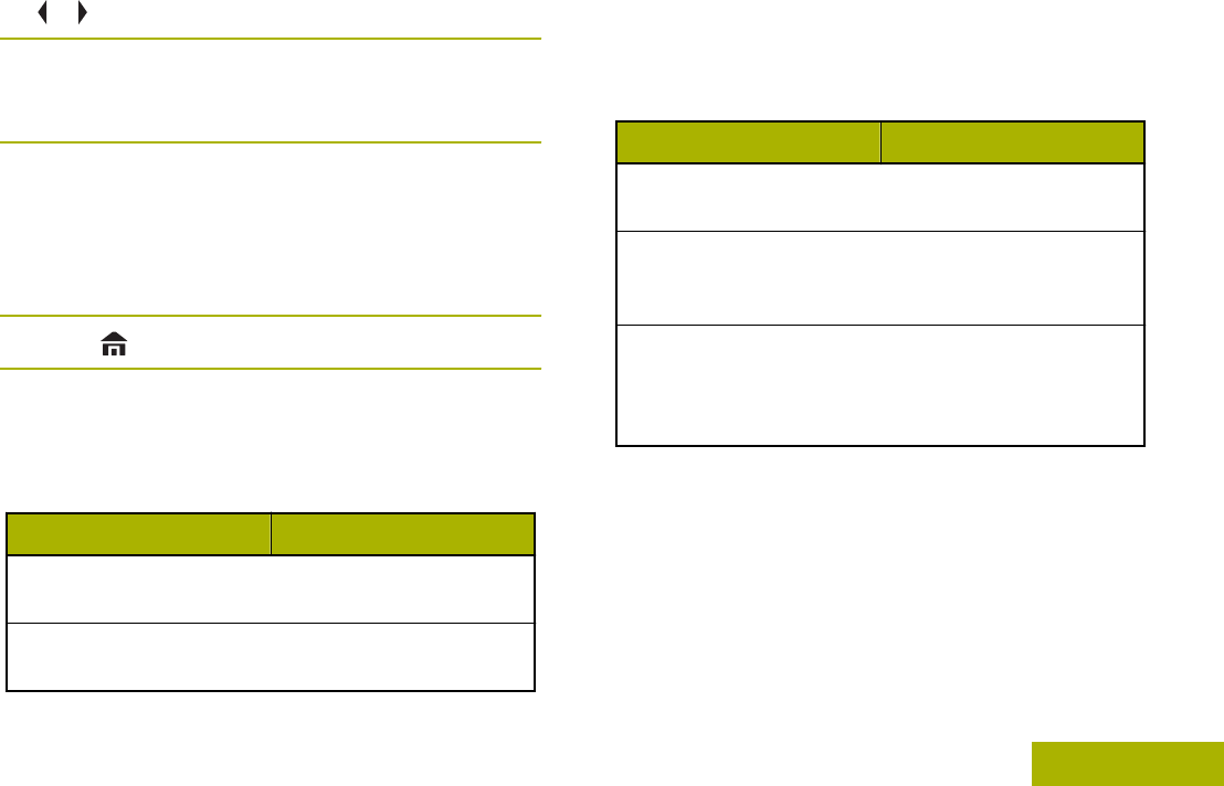
1 or to SQL.
2Press the Menu Select button directly below SQL.
The display shows SQUELCH XX, where XX is the
value for the current squelch.
3Perform one of the following actions:
•Press the Menu Select button directly below
“+” to increase the squelch volume.
•Press the Menu Select button directly below “-”
to decrease the squelch volume.
4Press to return to the selected channel.
Analog Options
Tone Private Line (PL), Digital Private-Line (DPL),
and carrier squelch can be available
(preprogrammed) per channel.
Mode Result
Carrier squelch (C) You hear all traffic on a
channel.
PL or DPL The radio responds only
to your messages.
Digital Options
One or more of the following options may be
preprogrammed in your radio. Check with your dealer
or system administrator for more information.
Option Result
Digital Carrier-Operated
Squelch (COS) You hear any digital traf-
fic.
Normal Squelch You hear any digital traf-
fic having the correct net-
work access code.
Selective Switch You hear any digital traf-
fic having the correct net-
work access code and
correct talkgroup.
Using the PL Defeat Feature
This feature allows you to override any coded squelch
(DPL or PL) that might be preprogrammed to a
channel. The radio also unmutes to any digital activity
on a digital channel.
Place the preprogrammed PL Defeat switch in the
PL Defeat position.
Advanced Features
133
English
Draft

One of the following scenarios occurs:
• You hear any activity on the channel.
• The radio is muted if no activity is present.
Note:
When this feature is active, the Carrier
Squelch status indicator is displayed.
Digital PTT ID Support
This feature allows you to see the radio ID (number)
of the radio from whom you are currently receiving a
transmission. This ID, consisting up to a maximum of
eight characters, can be viewed by both the receiving
radio and the dispatcher.
The ID number of your radio is also automatically sent
every time the PTT button is pressed. This is a per-
channel feature. For digital voice transmissions, the
ID of your radio is sent continuously during the voice
message.
Smart PTT Feature (Conventional Only)
Smart PTT is a per-personality, programmable
feature used in conventional radio systems to keep
radio users from talking over other radio
conversations.
When smart PTT is enabled in your radio, you cannot
transmit on an active channel.
If you try to transmit on an active smart-PTT channel,
you hear an alert tone, and the transmission is
inhibited. The LED lights up solid yellow to indicate
that the channel is busy.
The following table shows the variations of smart
PTT:
Mode Description
Transmit Inhibit
on Busy Chan-
nel with Carrier
You cannot transmit if any traffic
is detected on the channel.
Transmit Inhibit
on Busy Chan-
nel with Wrong
Squelch Code
You cannot transmit on an active
channel with a squelch code or (if
secure-equipped) encryption key
other than your own. If the PL
code is the same as yours, the
transmission is not prevented.
Quick-Key Over-
ride Your radio must be preprogram-
med to allow you to use Quick-
Key Override. This feature can
work in conjunction with either of
the two above variations. You
Advanced Features
134
English
Draft
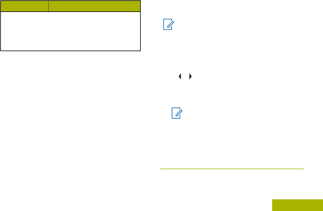
Mode Description
can override the transmit-inhibit
state by quick-keying the radio. In
other words, two PTT button
presses within the preprogram-
med time limit.
Transmit Inhibit
This feature is available for APCO 25 trunking, Type II
trunking and Conventional operations for all APX
radios.
When Transmit Inhibit feature is enabled, the radio
stops all transmission including voice and data. The
radio can receive messages but is not able to reply
the acknowledgment request of the received
message.
User can physically control the transmission of the
radio especially during operation in hazardous
environments with this feature. An environment is
considered hazardous when the power emitted by the
radio power amplifier could initiate an explosion or
other dangerous reactions.
When the Transmit Inhibit feature is disabled, the
radio functions according to its normal operations.
The radio sounds alert tone when user enters or exits
this feature and also when PTT is pressed.
Note:
Acknowledgement of any messages required
from the radio is not transmitted if the Transmit
Inhibition is enabled.
Enabling Transmit Inhibition
Perform one of the following actions:
• or to TXIN. Press the Menu Select button
below TXIN.
• Turn off the ignition through Ignition Sense
Line.
Note:
If the user has disabled TX Inhibit via the
menu and then moves the switch to the
position where TX Inhibit is enabled, the
new value overwrites the menu value.
The display shows TX INHIBIT ON. You hear a
sequence of short, low-high tones to indicate
transmission is inhibited.
Pressing PTT triggers the radio sounds a constant
short, low-pitched tone (reject tone).
Advanced Features
135
English
Draft

Note:
The status of the Transmit Inhibit does not
change after the radio powers up.
The softkey TXIN is created to ease the user
of inhibition transmission besides relying
solely on Ignition Sense Line. Only if the
Ignition Sense Line is on, the softkey TXIN
works. If the Ignition Sense Line is on, user
can always turn on or off the Transmit
Inhibition using the softkey TXIN; but when the
Ignition Sense Line is off, function of softkey
TXIN is suspended, and the Transmit
Inhibition function is always off.
If PTT TX Inhibit is enabled, when using multi control
head with one active configuration, with the PTT
pressed on the active control head, any press on the
programmable button of the other control head which
meant for that control head to be active control head
will cause an unstoppable long low-pitched tone (Talk
Prohibit Tone). The display shows TX INHIBIT This
behavior can be stopped by pressing PTT button
again on the active control head
Disabling Transmit Inhibition
Perform one of the following actions:
• or to TXIN. Press the Menu Select button
below TXIN.
• Turn on the ignition through Ignition Sense
Line.
Note:
If the user has disabled TX Inhibit via the
softkey and then moves the switch to the
position where TX Inhibit is enabled, the
new value overwrites the menu value.
The display shows TX INHIBIT OFF. You hear a
sequence of short, high-low tone (Transmit Inhibit
Off tone) to indicate transmission is back to normal
operation.
General Radio Information
Your radio contains information on the following:
• Radio Information
• IP Display
• Control Assignments
Note:
The radio automatically exits the feature, if the
feature inactivity timer is enabled, when the
radio is left idle and the timer expires. You
Advanced Features
136
English
Draft
hear the Menu Inactive Exit Tone upon feature
exit.
Accessing the Radio Information
This feature displays the following radio information:
• Host Version
• Secure Version
• CH 1 – 4 Version (depending on the number of
channels connected.)
• Siren Version
• Model Number
• ESN
• Flash Code
• Tuning Version
• DSP Version
• KG (Secure Algorithm)
• Serial Number
• Flash Size & Type
• RF Band(s)
• Processor Version
• MCHIB Version
• CHIB Version
• TIB Version
• TRC Version
• VRS Version
• URC Version
• DVRS App Version (only when DVRS is available)
• DVRS DSP Version (only when DVRS is
available)
• DVRS CP Version (only when DVRS is available)
• AUX CH Version
Note:
To return to the Home screen, press at any
time.
1 or to INFO and press the Menu Select button
directly below INFO.
2 or to RADIO INFO and press the Menu Select
button directly below SEL.
The display shows the Information screen.
3Perform one of the following actions:
• or to scroll through the various information.
•Press the Menu Select button directly below
BACK to return to the previous screenp.
•Press to return to the Home screen .
Advanced Features
137
English
Draft
Viewing the IP Information
This feature displays the device name, IP address,
and status of your radio.
Note:
The device name of your radio is
preprogrammed. Check with your dealer or
system administrator for more information.
1Perform one of the following actions:
•Press the preprogrammed Info button.
• or to INFO and press the Menu Select
button directly below INFO.
2 or to IP INFO and press the Menu Select
button directly below SEL.
3Perform one of the following actions:
• or to scroll through the various information.
•Press the Menu Select button directly below
BACK to return to the previous screen.
•Press to return to the Home screen.
Viewing the Control Assignments
This feature displays the programmable radio
functions assigned to the controls of your radio for the
currently selected channel.
See Programmable Features on page 23 for more
information on the various programmable features of
your radio.
1Perform one of the following actions:
• Press the preprogrammed Info button.
• or to INFO and press the Menu Select
button directly below INFO.
2 or to CONTROL MAP and press the Menu Select
button directly below SEL.
The display shows the Control Map screen.
3Perform one of the following actions:
• or to scroll through the various information.
•Press the Menu Select button directly below
BACK to return to the previous screen.
•Press to return to the Home screen.
Advanced Features
138
English
Draft

External Alarms (Horn and Lights)
All control heads can be equipped for external alarms
(horn and lights) that are activated when a Call Alert
page, Private Conversation call, or phone call is
received.
The radio always powers up with the horn and lights
feature enabled.
Note:
The horn and lights feature must be enabled
by a qualified radio technician.
Using Non-Permanent Horn and Lights
1Press the Menu Select button directly below H/L
momentarily.
The last selected alarm(s) are enabled, and the
display shows the enabled alarm(s) alternating
with the selected mode, until it is turned off.
2Press the Menu Select button directly below H/L
momentarily to turn off the alarm(s).
The display shows HORN/LITES OFF.
Using Permanent Horn and Lights
If Permanent Horn and Lights is enabled, horn and
lights will automatically turn on when the radio powers
up.
1Press the Menu Select button directly below H/L
once to turn off the alarm(s).
2Press the Menu Select button directly below H/L
momentarily to enable the last selected alarm(s).
The display briefly shows the enabled alarms, and
then reverts back to the selected mode.
Changing the Selected Alarms
1Press the Menu Select button directly below H/L
until the display shows the required alarm.
2Perform one of the following actions:
•Press the Menu Select button directly below H
+L to turn on both horn and lights.
•Press the Menu Select button directly below
Lgts to turn on the lights.
•Press the Menu Select button directly below
Horn to turn on the horn.
Advanced Features
139
English
Draft

One of the following scenarios occurs:
• If you choose H+L, the display shows HORN/
LITES ON.
• If you choose LGTS, the display shows LIGHTS
ON.
• If you choose HORN, the display shows HORN
ON.
An OFF entry is shown at the softkey when one of
the alarms is active. Selecting OFF deactivates the
current active alarm.
Receiving a Call While Alarms are Turned On
When you receive a call with the Alarms turned on,
you hear the vehicle’s horn sounds for four seconds,
and/or the car lights turn on for 60 seconds.
The display shows the type of call received (CALL,
PAGE, or PHONE) and the selected mode name.
The time interval can be modified by a qualified radio
technician.
Turning Off Non-Rearmable External Alarms
1Perform one of the following actions:
•Press the Menu Select button directly below
CALL, PAGE or PHON to turn off the external
alarm(s) and access that feature.
•Press the PTT button or any control-head
button to turn off the external alarm(s).
The Volume Knob and the DIM button have no
effect on the state of the external alarm(s).
2Press the Menu Select button directly below H/L
momentarily to rearm the horn and lights feature.
Turning Off Rearmable External Alarms
Perform one of the following actions:
•Press the Menu Select button directly below
CALL, PAGE or PHON to turn off the external
alarm(s) and access that feature. The external
alarm(s) is turned off and automatically
rearmed so that when you exit the entry, the
external alarm(s) will automatically turn on.
•Press the PTT button or any control head
button other than the Menu Select button
directly below H/L to turn off the external
alarm(s). The external alarm(s) is turned off
and automatically rearmed so that when you
Advanced Features
140
English
Draft

exit the entry, the external alarm(s) will
automatically turn on.
•Press the Menu Select button directly below
H/L to turn off the external alarm(s) and exit the
Horn and Lights feature. Press the Menu
Select button directly below H/L momentarily
to rearm the horn and lights feature.
The Volume Knob and the DIM button have no
effect on the state of the external alarm(s).
Advanced Features
141
English
Draft
Helpful Tips
Radio Care
The following are suggestions to assist you in
troubleshooting possible operating problems.
Caution:
The cables that connect to the rear of the
radio could have live voltage on some of their
pins. Do not remove or reconnect these
cables. Only a qualified radio technician
should perform this task. Service performed by
unauthorized personnel may cause the radio
to transmit an emergency alarm even if the
unit is turned off.
If your radio is locked up or the display shows FAIL
01/09, turn the radio off and then back on. If this
does not correct the condition, take the radio to a
qualified radio technician for service.
If radio operation is intermittent, check with other
persons using the system for similar problems before
taking the radio in for service. Similar problems
indicate a system malfunction rather than a radio
failure.
If symptoms persist or, if your unit exhibits other
problems, contact a qualified radio technician.
Cleaning the External Surface of the Radio
Caution:
Do not use solvents to clean your radio.
Spirits may permanently damage the radio
housing.
Do not submerge the radio in detergent
solution.
1Combine one teaspoon of mild diswashing
detergent to one gallon of water (0.5% solution).
2Apply the solution sparingly with a stiff, non-
metallic, short-bristled brush, making sure excess
detergent does not get entrapped near the
connectors, controls or crevices.
3Dry the radio thoroughly with a soft, lint-free cloth.
Cleaning the External Plastic Surface
The detergent-water solution should be applied
sparingly with a stiff, non-metallic, short-bristled brush
to work all loose dirt away from the radio.
Helpful Tips
142
English
Draft

A soft, absorbent, lint-free cloth or tissue should be
used to remove the solution and dry the radio.
Make sure that no water remains entrapped near the
connectors, cracks, or crevices.
Helpful Tips
143
English
Draft

Accessories
The accessory link below is for APX radios. Not all
accessories are FCC certified to operate with all APX
models and/or bandsplits. Please refer to the specific
APX radio price pages for a list of FCC certified
accessories or contact your sales representative for
accessory compatibility.
http://www.motorolasolutions.com/APX
Note:
GPS only antenna is only used in either a
single band UHF or 700/800 application where
the Public Safety Microphone (PSM) is used
with the corresponding PSM antenna. This
antenna is only for GPS reception and cannot
be used for receive/transmit operation at UHF,
VHF or 700/800. This antenna is never to be
used on the PSM.
Accessories
144
English
Draft

Maritime Radio Use in the VHF
Frequency Range
Special Channel Assignments
Emergency Channel
If you are in imminent and grave danger at sea and
require emergency assistance, use VHF Channel 16
to send a distress call to nearby vessels and the
United States Coast Guard. Transmit the following
information, in this order:
1“MAYDAY, MAYDAY, MAYDAY.”
2“THIS IS _____________________, CALL SIGN
__________.” State the name of the vessel in
distress 3 times, followed by the call sign or other
identification of the vessel, stated 3 times.
3Repeat “MAYDAY” and the name of the vessel.
4“WE ARE LOCATED AT
_______________________.” State the position
of the vessel in distress, using any information that
will help responders to locate you, e.g.:
• latitude and longitude
• bearing (state whether you are using true or
magnetic north)
• distance to a well-known landmark
• vessel course, speed or destination
5State the nature of the distress.
6Specify what kind of assistance you need.
7State the number of persons on board and the
number needing medical attention, if any.
8Mention any other information that would be
helpful to responders, such as type of vessel,
vessel length and/or tonnage, hull color, etc.
9“OVER.”
10 Wait for a response.
11 If you do not receive an immediate response,
remain by the radio and repeat the transmission at
intervals until you receive a response. Be
prepared to follow any instructions given to you.
Non-Commercial Call Channel
For non-commercial transmissions, such as fishing
reports, rendezvous arrangements, repair scheduling,
or berthing information, use VHF Channel 9.
Operating Frequency Requirements
A radio designated for shipboard use must comply
with Federal Communications Commission Rule Part
80 as follows:
Maritime Radio Use in the VHF Frequency Range
145
English
Draft
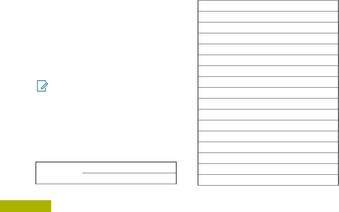
• on ships subject to Part II of Title III of the
Communications Act, the radio must be capable of
operating on the 156.800 MHz frequency.
• on ships subject to the Safety Convention, the
radio must be capable of operating:
• in the simplex mode on the ship station
transmitting frequencies specified in the
156.025 – 157.425 MHz frequency band, and
• in the semiduplex mode on the two frequency
channels specified in the table below.
Note:
Simplex channels 3, 21, 23, 61, 64, 81, 82,
and 83 cannot be lawfully used by the general
public in US waters.
Additional information about operating
requirements in the Maritime Services can be
obtained from the full text of FCC Rule Part 80
and from the US Coast Guard.
Table 1: VHF Marine Channel List
Channel Num-
ber Frequency (MHz)
Transmit Receive
1 156.050 160.650
2 156.100 160.700
* 156.150 160.750
4 156.200 160.800
5 156.250 160.850
6 156.300 –
7 156.350 160.950
8 156.400 –
9 156.450 156.450
10 156.500 156.500
11 156.550 156.550
12 156.600 156.600
13** 156.650 156.650
14 156.700 156.700
15** 156.750 156.750
16 156.800 156.800
17** 156.850 156.850
Maritime Radio Use in the VHF Frequency Range
146
English
Draft

18 156.900 161.500
19 156.950 161.550
20 157.000 161.600
* 157.050 161.650
22 157.100 161.700
* 157.150 161.750
24 157.200 161.800
25 157.250 161.850
26 157.300 161.900
27 157.350 161.950
28 157.400 162.000
60 156.025 160.625
* 156.075 160.675
62 156.125 160.725
63 156.175 160.775
* 156.225 160.825
65 156.275 160.875
66 156.325 160.925
67** 156.375 156.375
68 156.425 156.425
69 156.475 156.475
71 156.575 156.575
72 156.625 –
73 156.675 156.675
74 156.725 156.725
75 *** ***
76 *** ***
77** 156.875 –
78 156.925 161.525
79 156.975 161.575
80 157.025 161.625
* 157.075 161.675
* 157.125 161.725
* 157.175 161.775
Maritime Radio Use in the VHF Frequency Range
147
English
Draft
84 157.225 161.825
85 157.275 161.875
86 157.325 161.925
87 157.375 161.975
88 157.425 162.025
Note:
* Simplex channels 3, 21, 23, 61, 64, 81, 82,
and 83 cannot be lawfully used by the
general public in US waters.
** Low power (1 W) only.
*** Guard band.
Note:
A – in the Receive column indicates that the
channel is transmit only.
Declaration of Compliance for the Use of
Distress and Safety Frequencies
The radio equipment does not employ a modulation
other than the internationally adopted modulation for
maritime use when it operates on the distress and
safety frequencies specified in RSS-182 Section 7.3.
Technical Parameters for Interfacing External
Data Sources
RS232 USB SB9600
Input Volt-
age (Volts
Peak-to-
peak)
18V 3.6V 5V
Max Data
Rate 115 Kbps 12 Mbps 9.6 Kbps
Impedance 5000 Ohm 90 Ohm 120 Ohm
Maritime Radio Use in the VHF Frequency Range
148
English
Draft

Glossary
This glossary is a list of specialized terms used in this
manual.
ACK Acknowledgment of
communication.
Active Channel A channel that has traffic on it.
Analog Signal An RF signal that has a
continuous nature rather than a
pulsed or discrete nature.
ARS Automatic Registration Service
ASTRO 25 Motorola standard for wireless
digital trunked communications.
ASTRO
Conventional Motorola standard for wireless
digital conventional
communications.
Autoscan A feature that allows the radio
to automatically scan the
members of a scan list.
AUX CH Auxiliary Control Head
Call Alert Privately page an individual by
sending an audible tone.
Carrier Squelch Feature that responds to the
presence of an RF carrier by
opening or unmuting (turning
on) a receiver’s audio circuit. A
squelch circuit silences the
radio when no signal is being
received so that the user does
not have to listen to “noise”.
Central Controller A software-controlled,
computer-driven device that
receives and generates data
for the trunked radios assigned
to it. It monitors and directs the
operations of the trunked
repeaters.
Channel A group of characteristics such
as transmit/ receive frequency
pairs, radio parameters, and
encryption encoding.
CHIB Control Head Interface Board
Glossary
149
English
Draft

Control Channel In a trunking system, one of the
channels that is used to
provide a continuous, two-way/
data communications path
between the central controller
and all radios on the system.
Conventional Typically refers to radio-to-
radio communications,
sometimes through a repeater
(see Trunking).
Conventional
Scan List A scan list that includes only
conventional channels.
CP Codeplug
Cursor A visual tracking marker (a
blinking line) that indicates a
location on the display.
Deadlock Displayed by the radio after
three failed attempts to unlock
the radio. The radio must be
powered off and on prior to
another attempt.
Digital Private
Line (DPL) A type of coded squelch using
data bursts. Similar to PL
except a digital code is used
instead of a tone.
Digital Signal An RF signal that has a pulsed,
or discrete, nature, rather than
a continuous nature.
Dispatcher An individual who has radio
system management duties.
DSP Digital Signal Processing
Dynamic
Regrouping A feature that allows the
dispatcher to temporarily
reassign selected radios to a
single special channel so they
can communicate with each
other.
DVRS Digital Vehicular Repeater
System
ESN Electrical Serial Number
Failsoft A feature that allows
communications to take place
even though the central
controller has failed. Each
trunked repeater in the system
transmits a data word informing
Glossary
150
English
Draft

every radio that the system has
gone into failsoft.
FCC Federal Communications
Commission.
FM Frequency Modulation
Hang Up Disconnect.
Home screen The first display information
after the radio completes its
self test.
KVL Key-variable loader: A device
for loading encryption keys into
the radio.
LCD Liquid crystal display.
LED Light-emitting diode.
MCHB Millennium Control Head Board
Menu Entry A software-activated feature
shown at the bottom of the
display – selection of these
features is controlled by the
button.
Monitor Check channel activity by
pressing the Monitor button. If
the channel is clear, you hear
static. If the channel is in use,
you hear conversation. It also
serves as a way to check the
volume level of the radio, since
the radio “opens the squelch”
when the monitor button is
pressed.
Multi-System
Talkgroup Scan
List
A scan list that can include
both talkgroups (trunked) and
channels (conventional).
Network Access
Code Network Access Code (NAC)
operates on digital channels to
reduce voice channel
interference between adjacent
systems and sites.
Non-Tactical/
Revert The user talks on a
preprogrammed emergency
channel. The emergency alarm
is sent out on this same
channel.
OTAR Over-the-air rekeying.
Glossary
151
English
Draft

Page A one-way alert, with audio
and/or display messages.
Personality A set of unique features
specific to a radio.
PIN Personal Identification Number
Preprogrammed Refers to a software feature
that has been activated by a
qualified radio technician.
Private
(Conversation)
Call
A feature that lets you have a
private conversation with
another radio user in the
talkgroup.
Private Line (PL) A sub-audible tone that is
transmitted such that only
receivers decoding the tone
receives it.
Programmable Refers to a radio control that
can have a radio feature
assigned to it.
PTT Push-To-Talk. The PTT button
engages the transmitter and
puts the radio in transmit
(send) operation when
pressed.
Radio Frequency
(RF) The part of the general
frequency spectrum between
the audio and infrared light
regions (about 10 kHz to
10,000,000 MHz).
Repeater A conventional radio feature,
where you talk through a
receive/transmit facility that re-
transmits received signals, in
order to improve
communications range and
coverage.
Selective Call A feature that allows you to call
a selected individual, intended
to provide privacy and to
eliminate the annoyance of
having to listen to
conversations of no interest to
you.
Selective Switch Any digital P25 traffic having
the correct Network Access
Code and the correct talkgroup.
Glossary
152
English
Draft

Squelch Special electronic circuitry,
added to the receiver of a
radio, that reduces, or cuts off,
unwanted signals before they
are heard in the speaker.
Standby An operating condition whereby
the radio’s speaker is muted
but still continues to receive
data.
Status Calls Pre-defined text messages that
allow the user to send a
conditional message without
talking.
Tactical/ Non-
Revert The user talks on the channel
that was selected before the
radio entered the emergency
state.
Talkaround Bypass a repeater and talk
directly to another unit for easy
local unit-to-unit
communications.
Talkgroup An organization or group of
radio users who communicate
with each other using the same
communication path.
TMS Text Messaging Service
Trunking The automatic sharing of
communications paths between
a large number of users (see
Conventional).
Trunking Priority
Monitor Scan List A scan list that includes
talkgroups that are all from the
same trunking system.
USK Unique Shadow Key.
UTC Coordinated Universal Time.
The international time standard
(formerly Greenwich Mean
Time, or GMT). Zero hours
UTC is midnight in Greenwich,
England, which is located at 0
degrees longitude. Everything
east of Greenwich (up to 180
degrees) is later in time;
everything west is earlier.
There are 42 time authorities
around the world that are
constantly synchronizing with
Glossary
153
English
Draft

each other. Abbreviated as
UTC (English backronym =
Universal Time, Coordinated),
it is also known as Zulu (Z)
Time.
VRS Vehicular Repeater System
Zone A grouping of channels.
Glossary
154
English
Draft

Limited Warranty
MOTOROLA COMMUNICATION PRODUCTS
I. WHAT THIS WARRANTY COVERS AND FOR
HOW LONG:
MOTOROLA SOLUTIONS, INC. (“MOTOROLA”)
warrants the MOTOROLA manufactured
Communication Products listed below (“Product”)
against defects in material and workmanship under
normal use and service for a period of time from the
date of purchase as scheduled below:
ASTRO APX Mobile Ra-
dios One (1) Year
Product Accessories One (1) Year
MOTOROLA, at its option, will at no charge either
repair the Product (with new or reconditioned parts),
replace it (with a new or reconditioned Product), or
refund the purchase price of the Product during the
warranty period provided it is returned in accordance
with the terms of this warranty. Replaced parts or
boards are warranted for the balance of the original
applicable warranty period. All replaced parts of
Product shall become the property of MOTOROLA.
This express limited warranty is extended by
MOTOROLA to the original end user purchaser only
and is not assignable or transferable to any other
party. This is the complete warranty for the Product
manufactured by MOTOROLA. MOTOROLA
assumes no obligations or liability for additions or
modifications to this warranty unless made in writing
and signed by an officer of MOTOROLA.
Unless made in a separate agreement between
MOTOROLA and the original end user purchaser,
MOTOROLA does not warrant the installation,
maintenance or service of the Product.
MOTOROLA cannot be responsible in any way for
any ancillary equipment not furnished by MOTOROLA
which is attached to or used in connection with the
Product, or for operation of the Product with any
ancillary equipment, and all such equipment is
expressly excluded from this warranty. Because each
system which may use the Product is unique,
MOTOROLA disclaims liability for range, coverage, or
operation of the system as a whole under this
warranty.
Limited Warranty
155
English
Draft

MOTOROLA offers the following optional extended
service contracts.
SERVICE FROM THE START (SfS)
COMPREHENSIVE
Provides for extended hardware repair coverage
INCLUDING CHEMICAL, LIQUID, FIRE, AND
OTHER PHYSICAL DAMAGE. Comprehensive
coverage is available in conjunction with
MOTOROLA’S standard Commercial Warranty and
starts from the FIRST DAY the radio is put into use.
Service performed under this plan consists of repair
or replacement of the covered equipment as set forth
in the terms and conditions. Repairs will be made only
at the designated MOTOROLA repair depot. Local
services are not included. MOTOROLA will pay the
inbound shipping charges only with use of the
MOTOROLA designated delivery service.
MOTOROLA will pay for outbound shipping via
MOTOROLA'S normal shipping methods.
SERVICE FROM THE START (SfS) LITE
Provides extended hardware normal wear and tear
repair coverage beginning AFTER MOTOROLA’S
standard Commercial Warranty period expires.
Service performed under this plan consists of repair
of the covered equipment as set forth in the terms
and conditions. Repairs will be made only at the
designated MOTOROLA repair depot. Local services
are not included. MOTOROLA will pay for outbound
shipping via MOTOROLA'S normal shipping methods.
II. GENERAL PROVISIONS:
This warranty sets forth the full extent of
MOTOROLA'S responsibilities regarding the Product.
Repair, replacement or refund of the purchase price,
at MOTOROLA’s option, is the exclusive remedy.
THIS WARRANTY IS GIVEN IN LIEU OF ALL
OTHER EXPRESS WARRANTIES. IMPLIED
WARRANTIES, INCLUDING WITHOUT LIMITATION,
IMPLIED WARRANTIES OF MERCHANTABILITY
AND FITNESS FOR A PARTICULAR PURPOSE,
ARE LIMITED TO THE DURATION OF THIS
LIMITED WARRANTY. IN NO EVENT SHALL
MOTOROLA BE LIABLE FOR DAMAGES IN
EXCESS OF THE PURCHASE PRICE OF THE
PRODUCT, FOR ANY LOSS OF USE, LOSS OF
TIME, INCONVENIENCE, COMMERCIAL LOSS,
LOST PROFITS OR SAVINGS OR OTHER
INCIDENTAL, SPECIAL OR CONSEQUENTIAL
DAMAGES ARISING OUT OF THE USE OR
INABILITY TO USE SUCH PRODUCT, TO THE
Limited Warranty
156
English
Draft

FULL EXTENT SUCH MAY BE DISCLAIMED BY
LAW.
III. STATE LAW RIGHTS:
SOME STATES DO NOT ALLOW THE EXCLUSION
OR LIMITATION OF INCIDENTAL OR
CONSEQUENTIAL DAMAGES OR LIMITATION ON
HOW LONG AN IMPLIED WARRANTY LASTS, SO
THE ABOVE LIMITATION OR EXCLUSIONS MAY
NOT APPLY.
This warranty gives specific legal rights, and there
may be other rights which may vary from state to
state.
IV. HOW TO GET WARRANTY SERVICE:
You must provide proof of purchase (bearing the date
of purchase and Product item serial number) in order
to receive warranty service and, also, deliver or send
the Product item, transportation and insurance
prepaid, to an authorized warranty service location.
Warranty service will be provided by MOTOROLA
through one of its authorized warranty service
locations. If you first contact the company which sold
you the Product (e.g., dealer or communication
service provider), it can facilitate your obtaining
warranty service. You can also call MOTOROLA at
1-800-927-2744 US/Canada.
V. WHAT THIS WARRANTY DOES NOT
COVER:
1Defects or damage resulting from use of the
Product in other than its normal and customary
manner.
2Defects or damage from misuse, accident, water,
or neglect.
3Defects or damage from improper testing,
operation, maintenance, installation, alteration,
modification, or adjustment.
4Breakage or damage to antennas unless caused
directly by defects in material workmanship.
5A Product subjected to unauthorized Product
modifications, disassembles or repairs (including,
without limitation, the addition to the Product of
non-MOTOROLA supplied equipment) which
adversely affect performance of the Product or
interfere with MOTOROLA's normal warranty
inspection and testing of the Product to verify any
warranty claim.
6Product which has had the serial number removed
or made illegible.
Limited Warranty
157
English
Draft

7Rechargeable batteries if:
• any of the seals on the battery enclosure of
cells are broken or show evidence of
tampering.
• the damage or defect is caused by charging or
using the battery in equipment or service other
than the Product for which it is specified.
8Freight costs to the repair depot.
9A Product which, due to illegal or unauthorized
alteration of the software/firmware in the Product,
does not function in accordance with
MOTOROLA’s published specifications or the FCC
certification labeling in effect for the Product at the
time the Product was initially distributed from
MOTOROLA.
10 Scratches or other cosmetic damage to Product
surfaces that does not affect the operation of the
Product.
11 Normal and customary wear and tear.
VI. PATENT AND SOFTWARE PROVISIONS:
MOTOROLA will defend, at its own expense, any suit
brought against the end user purchaser to the extent
that it is based on a claim that the Product or parts
infringe a United States patent, and MOTOROLA will
pay those costs and damages finally awarded against
the end user purchaser in any such suit which are
attributable to any such claim, but such defense and
payments are conditioned on the following:
1that MOTOROLA will be notified promptly in
writing by such purchaser of any notice of such
claim,
2that MOTOROLA will have sole control of the
defense of such suit and all negotiations for its
settlement or compromise, and
3should the Product or parts become, or in
MOTOROLA’s opinion be likely to become, the
subject of a claim of infringement of a United
States patent, that such purchaser will permit
MOTOROLA, at its option and expense, either to
procure for such purchaser the right to continue
using the Product or parts or to replace or modify
the same so that it becomes non-infringing or to
grant such purchaser a credit for the Product or
parts as depreciated and accept its return. The
depreciation will be an equal amount per year over
the lifetime of the Product or parts as established
by MOTOROLA.
MOTOROLA will have no liability with respect to any
claim of patent infringement which is based upon the
Limited Warranty
158
English
Draft

combination of the Product or parts furnished
hereunder with software, apparatus or devices not
furnished by MOTOROLA, nor will MOTOROLA have
any liability for the use of ancillary equipment or
software not furnished by MOTOROLA which is
attached to or used in connection with the Product.
The foregoing states the entire liability of
MOTOROLA with respect to infringement of patents
by the Product or any parts thereof.
Laws in the United States and other countries
preserve for MOTOROLA certain exclusive rights for
copyrighted MOTOROLA software such as the
exclusive rights to reproduce in copies and distribute
copies of such MOTOROLA software. MOTOROLA
software may be used in only the Product in which the
software was originally embodied and such software
in such Product may not be replaced, copied,
distributed, modified in any way, or used to produce
any derivative thereof. No other use including, without
limitation, alteration, modification, reproduction,
distribution, or reverse engineering of such
MOTOROLA software or exercise of rights in such
MOTOROLA software is permitted. No license is
granted by implication, estoppel or otherwise under
MOTOROLA patent rights or copyrights.
VII. GOVERNING LAW:
This Warranty is governed by the laws of the State of
Illinois, U.S.A.
VIII. For Australia Only
This warranty is given by Motorola Solutions Australia
Pty Limited (ABN 16 004 742 312) of Tally Ho
Business Park, 10 Wesley Court. Burwood East,
Victoria.
Our goods come with guarantees that cannot be
excluded under the Australia Consumer Law. You are
entitled to a replacement or refund for a major failure
and compensation for any other reasonably
foreseeable loss or damage. You are also entitled to
have the goods repaired or replaced if the goods fail
to be of acceptable quality and the failure does not
amount to a major failure.
Motorola Solutions Australia’s limited warranty above
is in addition to any rights and remedies you may
have under the Australian Consumer Law. If you have
any queries, please call Motorola Solutions Australia
at 1800 457 439. You may also visit our website:
http://www.motorolasolutions.com/XA-EN/Pages/
Contact_Us for the most updated warranty terms.
Limited Warranty
159
English
Draft

SERVICE
Proper repair and maintenance procedures will
assure efficient operation and long life for this
product. A Motorola maintenance agreement will
provide expert service to keep this and all other
communication equipment in perfect operating
condition. A nationwide service organization is
provided by Motorola to support maintenance
services. Through its maintenance and installation
program, Motorola makes available the finest service
to those desiring reliable, continuous communications
on a contract basis. For a contract service agreement,
please contact your nearest Motorola service or sales
representative, or an authorized Motorola dealer.
Express Service Plus (ESP) is an optional extended
service coverage plan, which provides for the repair
of this product for a period of three years from the
date of shipment from the factory, or the date of
delivery if purchased from an authorized Motorola
two-way radio dealer. For more information about
ESP, contact the Motorola Radio Support Center,
2204 Galvin Drive, Elgin, IL 60123, 1-800-227-6772.
Limited Warranty
160
English
Draft
Draft

Motorola Solutions, Inc.
1303 East Algonquin Road
Schaumburg, Illinois 60196 U.S.A.
MOTOROLA, MOTO, MOTOROLA SOLUTIONS and
the Stylized M logo are trademarks or registered trademarks
of Motorola Trademark Holdings, LLC and are used under license.
All other trademarks are the property of their respective owners.
© 2012–2016 Motorola Solutions, Inc. All rights reserved.
*6875947M01*
6875947M01-HC
Draft