Motorola Solutions 99FT3081 CDM1550LS+ 220MHz Mobile Radio User Manual 200 mobile quarter wave antenna
Motorola Solutions, Inc. CDM1550LS+ 220MHz Mobile Radio 200 mobile quarter wave antenna
Contents
Antenna Manual RESEND
Motorola, The Stylized M Logo, and Intelligence Everywhere are
registered trademarks of Motorola, Inc. 6880360B49-A
Copyright © 2000, 2002 Motorola, Inc. All Rights Reserved. *6880360B49*
Product Safety and RF Exposure
Compliance
ATTENTION!
This radio is restricted to occupational use only to
satisfy FCC RF energy exposure requirements. Before
using this product, read the RF energy awareness
information and operating instructions in the Product
Safety and RF Exposure booklet enclosed with your
radio (Motorola Publication part number
68P81095C99) to ensure compliance with RF energy
exposure limits.
Introduction
The antennas described in this section are supplied
with an appropriate antenna whip, coaxial cable and
connector, and mounting hardware. Mounting hard-
ware and installation is described for permanent vehi-
cle type mounting.
Refer to Table 1 for model identification. Figures 1
through 3 identify the component parts of the antenna.
Refer to the recommendations for antenna location
paragraph at the end of this instruction section for
safety information.
Installation
Mounting Hardware Installation – Roof
Mount
General
The installation procedure which follows is for a typi-
cal passenger car. The procedure may vary slightly
with the type of vehicle on which the antenna is to be
installed. Generally speaking, however, the procedures
outlined are of a universal nature.
NOTE
The antenna should be mounted on a flat
metal roof of .020 to .040 inch thickness.
1. First, select a location for the antenna as near
the center of the roof as possible.
2. The headlining may be probed with the fin-
gers to make sure that all points of obstruction
are avoided.
Installation Procedure Single Wall Construction
1. Locate the center of the roof by careful mea-
surement, remove the headlining as necessary,
CAUTION!
Before using this product, read the
operating instructions for safe usage
contained in the Product Safety and
RF Exposure booklet enclosed with
your radio.
Table 1. Model Complement
Antenna Model Frequency Range (MHz)
Roof Mount Models
RAD4012ARB
RAD4020ARB
HKAD4001A
RAE4022ARB
RAE4034ARB
RAF4021ARB
150.8-162
162-174
216-225
403-430
450-470
806-870
!
C a u t i o n
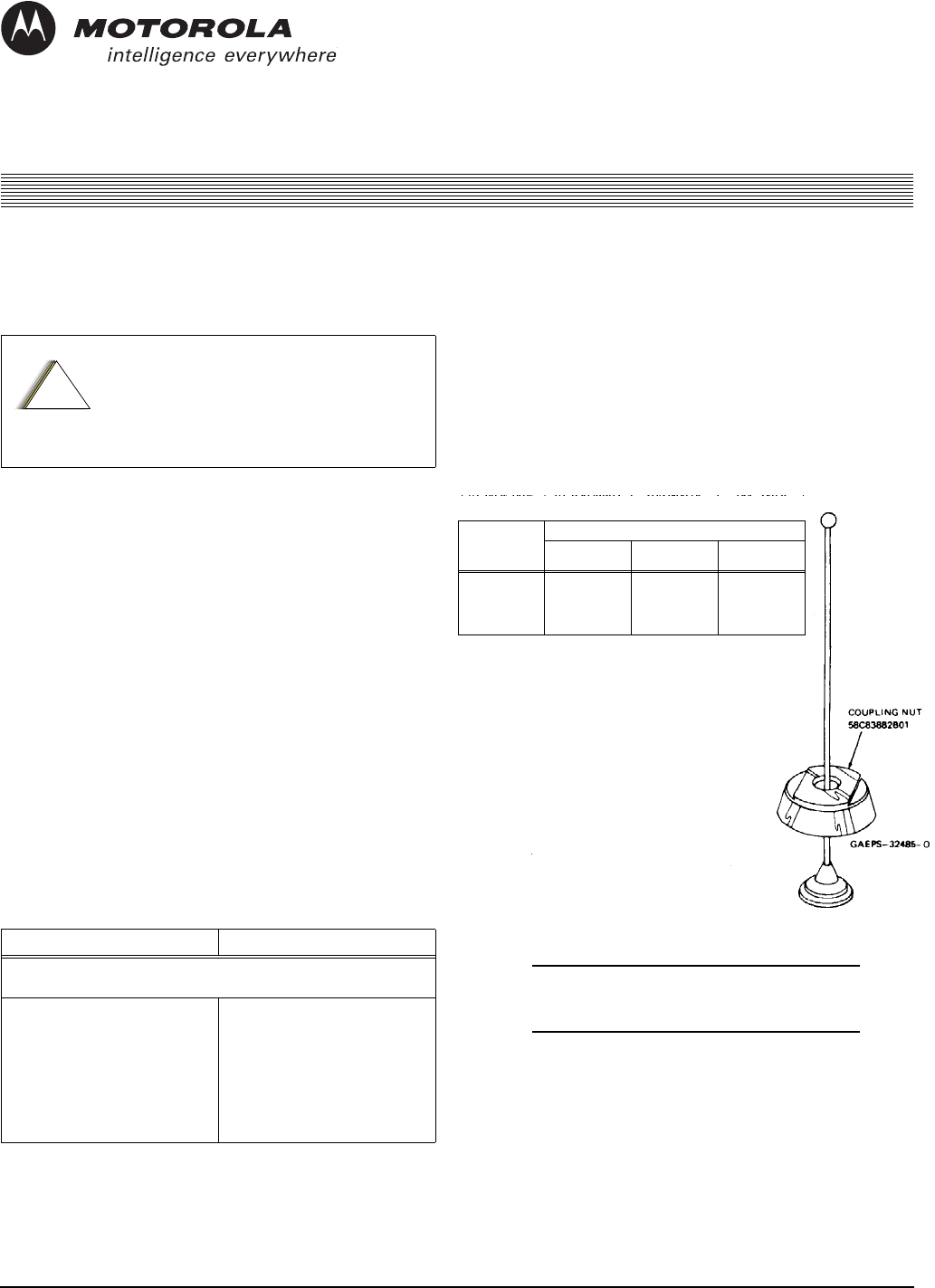
Figure 1. Whip Parts Identification
ROD WITH
CHROME NUT
(ROD)
ANTENNA ONLY
MOTOROLA
PART NO. ANTENNA
MODEL NO. FREQ. RANGE
(MHz)
01-80352A07
01-80352A08
01-80305K05
01-80352A11
01-80352A90
01-83938B03
01-83938B04
01-83938B12
01-83938B06
01-83938B11
RAD4012ARB
RAD4020ARB
HKAD4001A
RAE4034ARB
RAF4021ARB
150.8-162
162-174
216-225
450-470
806-870
Mobile 1/4-Wave Antennas
Roof Mount
26880360B49-A July, 2002
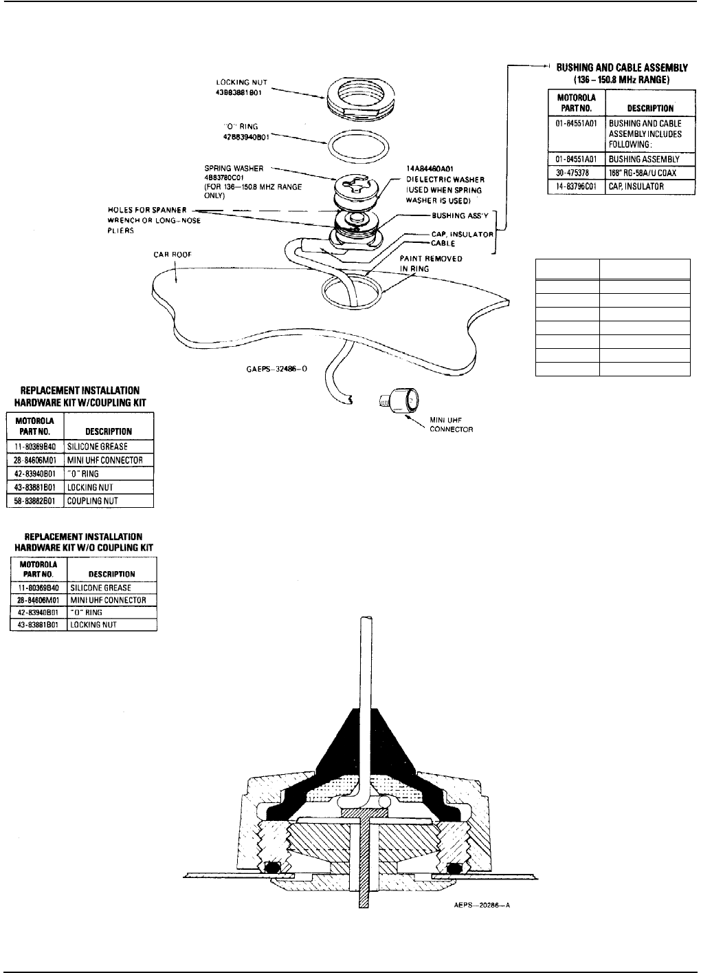
Mobile 1/4-Wave Antennas Installation
Figure 2. Roof Mount Parts Identification
01-80300B02
CABLE ASSEMBLY & INSTALLATION KIT
(150.8-174 MHz, 216-225 MHz, 403-470 MHz
AND 806-870 MHz RANGE)
MOTOROLA
PART NO. DESCRIPTION
01-84988K01 BUSHING ASSEMBLY
11-80369B40 SILICONE GREASE
14-83798C01 CAP, INSULATOR
28-84606M01 MINI UHF CONNECTOR
30-80336A10 14 FEET RG58A/U COAX
42-83940B01 “O” RING
43-83881B01 LOCKING NUT
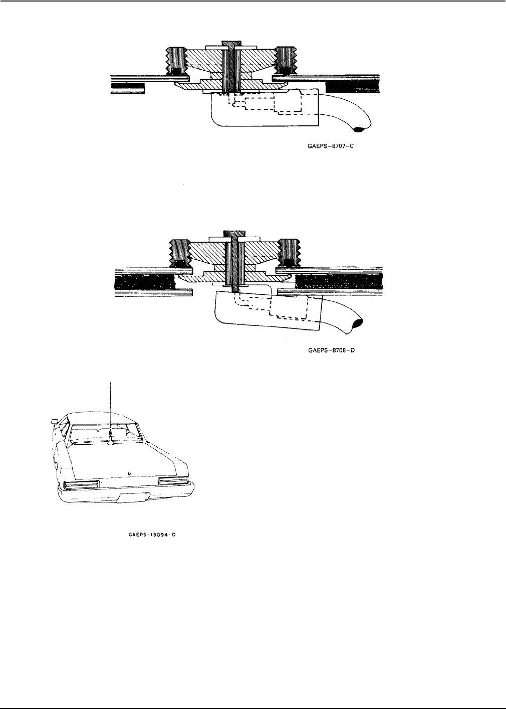
Figure 3. Cross-Section of Assembled Antenna
July, 2002 6880360B49-A 3
Installation Mobile 1/4-Wave Antennas
and drill a pilot hole down through the roof. If
the interior light of the car is centered in the
roof, remove this light and fixture and drill
the pilot hole up through the roof at about the
center of the interior light mountings. This
centers the antenna mount on the roof and
allows for easy access.
2. Drill a 3/4-inch hole from the top of the roof
until the saw bottoms. Use a Motorola hole
cutting saw (01-80382A25) or equivalent.
When the saw bottoms on the roof, it cleans
off the paint in a neat circle and assures good
contact with the locking nut.
IMPORTANT
For proper seating of brushing assembly,
remove burrs and scrape any foreign
matter from underside of hole out to at
least 1/8-inch from edge.
3. Determine the routing of the cable from the
antenna mounting base to the radio set; then
remove the molding and trim necessary to
facilitate pulling the cable through.
NOTE
To ensure ease of assembly, thread the
locking nut on and then off the bushing
assembly before installation. This
removes any burrs which may be present.
4. Refer to Figure 4. From the top, feed the
RG-58A/U lead-in cable between the headlin-
ing and the metal roof. Then route the cable
between the roof and the radio set.
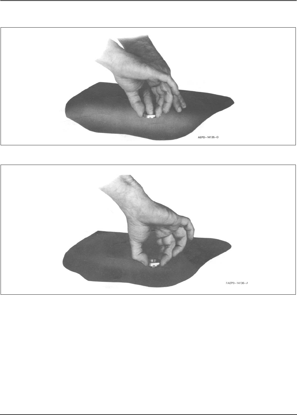
5. Refer to Figure 5. The bushing assembly is
now in a position to drop into the hole in the
roof. It should be tilted at a slight angle and
fed into the 3/4-inch hold. The threaded top
will not fall through the hole.
6. Refer to Figure 7. Hold the antenna bushing
assembly in place with the index finger and
thread the locking nut onto it as shown.
7. Pull up on the bushing assembly as illustrated
in Figure 8, and make sure it is centered and
seated (both shoulders inside the drilled hole),
and that the "O" ring is in the groove in the
locking nut. (As furnished, the "O" ring has
been placed in the locking nut groove and
imbedded in silicone grease.) Use a 15/
16-inch open-end wrench to tighten the lock-
ing nut until it bottoms firmly against the roof
top.
IMPORTANT
Refer to Figure 2. If the bushing assembly
should slip or rotate for any reason dur-
ing the tightening procedure, insert the
tips of a long nose plier or spanner
wrench into the two holes in the bushing
assembly and apply force to prevent
rotation until the locking nut is tight.
The locking nut must come into contact with the car
roof to insure the proper antenna radiation pattern.
This can only happen when the rubber "O" ring is fully
compressed.
8. Take up the slack in the cable and replace the
headlining retainer molding.
9. Replace headlining and dome light if
removed.
Installation Procedure - Double Wall Construction
Vehicles With Dome Lights or
Removable Headlining
1. Remove the dome light from its mount or remove
the headlining from the installation area.
2. Drill a small pilot hole centered in the roof of
the vehicle. The center of the cavity where the
dome light was removed is sufficiently close.
3. Using a 1-1/4-inch diameter hole saw cut a
hole in the inside layer of the metal.
4. Remove the metal and filler from this 1-1/
4-inch diameter hole.
Figure 4. Coaxial Cable Insertion Figure 5. Bushing Assembly Insertion
46880360B49-A July, 2002
Mobile 1/4-Wave Antennas Installation
5. Complete the installation per installation pro-
cedure given for vehicles with single wall con-
struction. A completed mount is illustrated in
Figure 9.
Vehicles Without Dome Lights
When the vehicle has no dome light, and it is not feasi-
ble to remove the headlining to get to the inside sur-
face, proceed as follows:
1. Locate the center of the roof and make sure
the area beneath this point is clear to allow
passage of a drill.
2. With a 3/4-inch diameter hole cutting saw
carefully cut a 3/4-inch hole from the top of
the roof through both thicknesses of metal.
Clean the metal in a neat circle around the
hole to assure a good contact between the roof
metal and the locking nut.
3. Remove any burrs and remove the filler sepa-
rating the roof thickness for a distance of 1/
4-inch back from the hole.
Figure 7. Locking Nut Positioning
Figure 8. Locking Nut Tightening
July, 2002 6880360B49-A 5
Installation Mobile 1/4-Wave Antennas
4. Install the mount to the outside roof thickness
per installation procedure given for vehicles
with single wall construction..
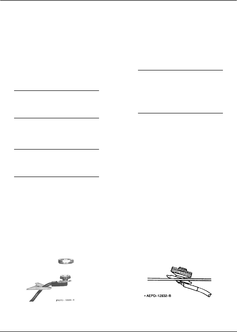
Mini-UHF Connector Installation
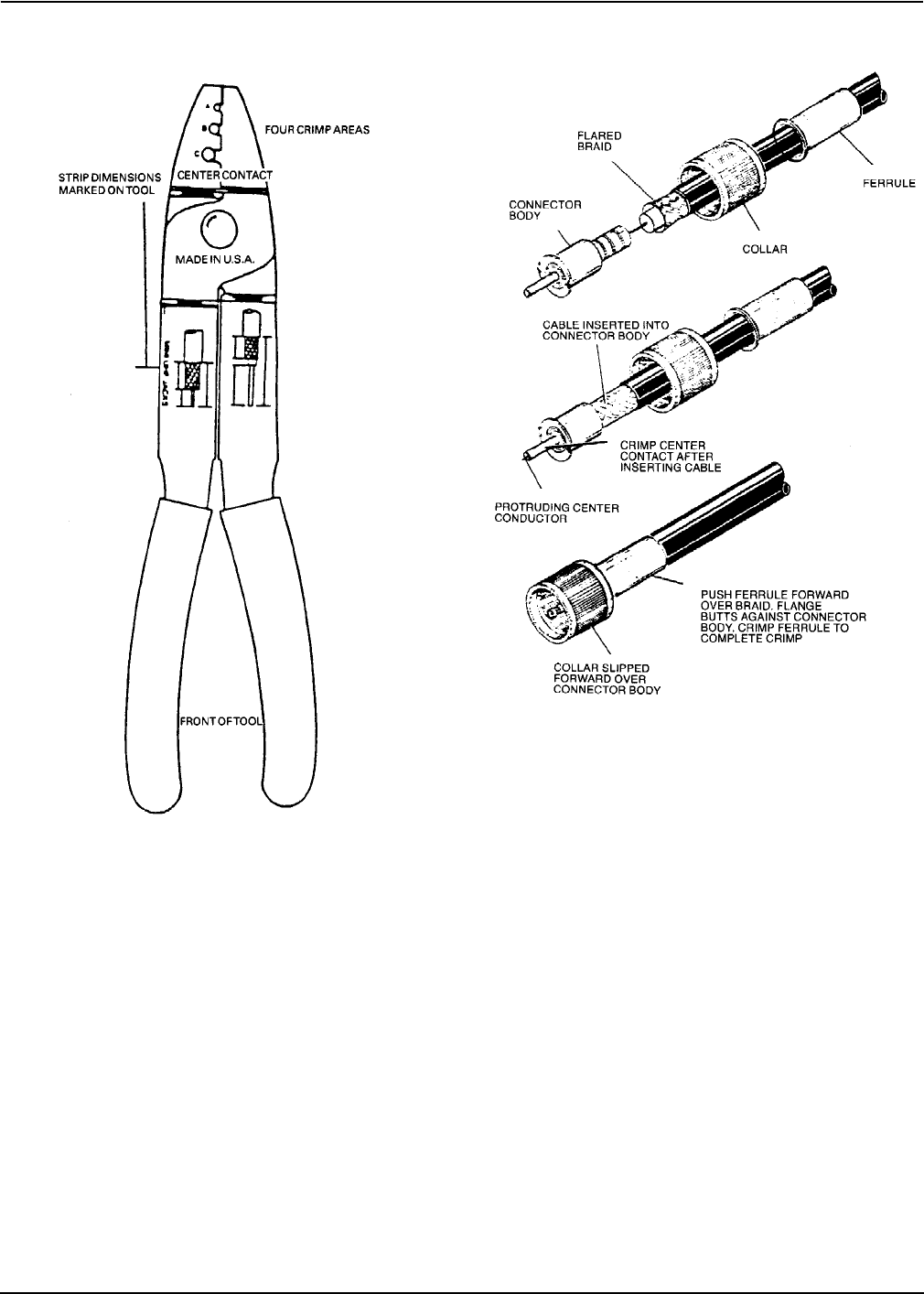
Use Motorola hand tool part #66-80388A26 (Refer to
Figure 12). A deluxe rachet type tool is available; order
part #66-80334B40.
Installation Instructions
1. Slip ferrule and collar onto cable. Refer to
Figure 13.
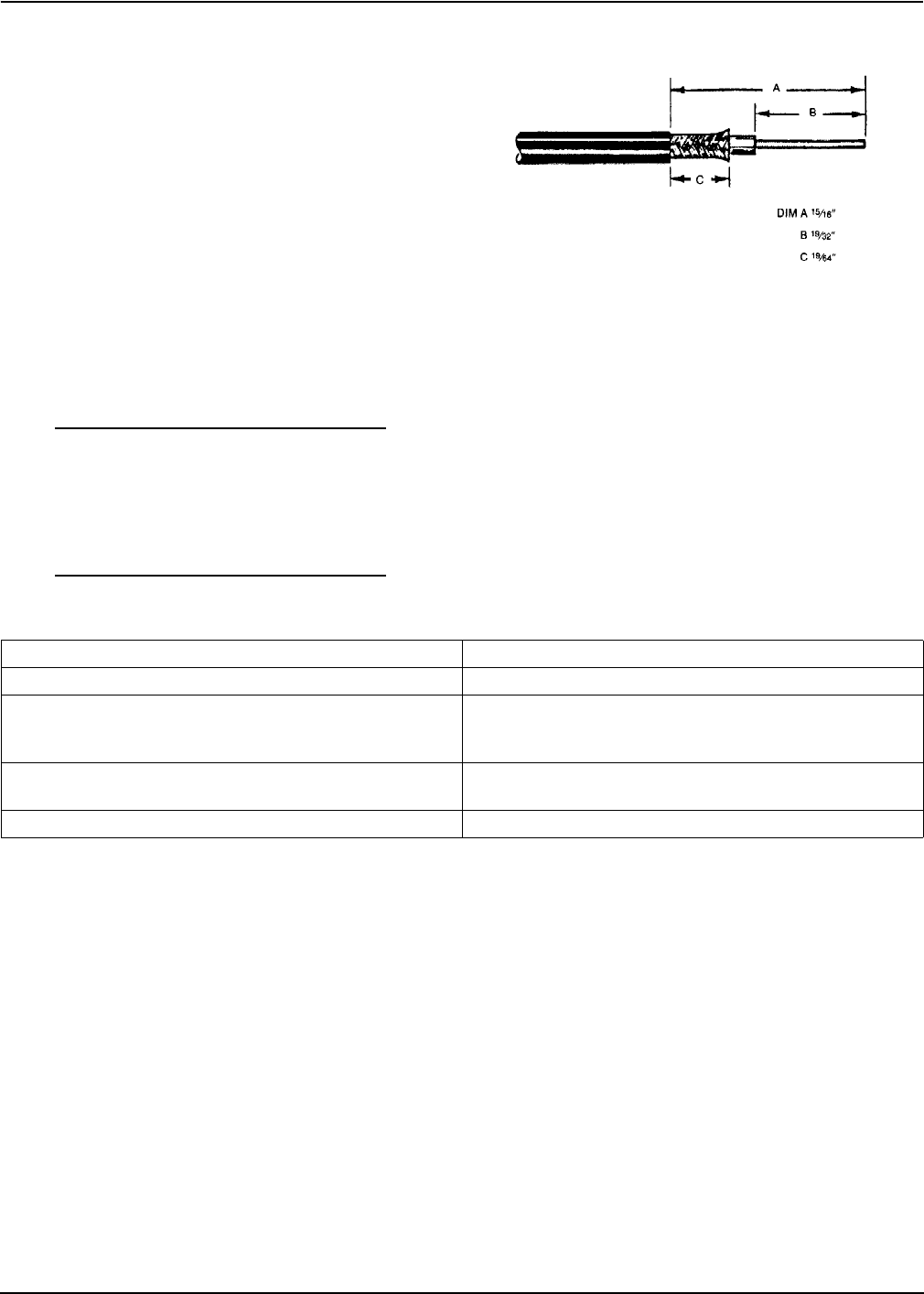
2. Prepare cable to strip dimensions per
Figure 14, which is also marked on the hand
tool.
3. Insert stripped cable into plug body until con-
ductor is exposed (front end) and dielectric
bottoms inside body. Refer to Figure 13.
4. Crimp center contact using proper crimp
section of tool. Refer to Figure 12 marked
"CENTER CONTACT."
5. Push collar forward onto plug assembly. Fit
cable braid over the support sleeve of the con-
nector. Refer to Figure 13.
6. Push ferrule over braid until flange butts
against connector body. Refer to Figure 13.
Using the correct crimp area of the tool, crimp
the ferrule close to the plug body. See
Figure 12, crimp location "C." Crimp ferrule a
second time close to the cable end.
7. The protruding center conductor should be
trimmed flush with the end of the center contact.
Figure 10. Roof Mount in Vehicle Without Dome Light
Figure 9. Roof Mount in Vehicle With
Dome Light or Removable Headlining
Figure 11. Typical Mount Location
66880360B49-A July, 2002
Mobile 1/4-Wave Antennas Frequency Conversion
Frequency Conversion
See Table 1. Antennas in each band are equipped with
whip radiators cut to the proper length for that specific
band. To change from one band to another, a whip
assembly of the proper length should be substituted
for one previously in use. Antennas in the 136-150.8
MHz range are also equipped with a spring washer
(roof mount models only; see Figure 2) to provide for
proper impedance matching. Should it be desired to
change from an antenna in the 136-150.8 MHz range to
one in the other ranges, this washer must be removed
in addition to changing the whip assembly. Con-
versely, to shift from the other ranges to the 136-
150.8 MHz range, a spring washer must be installed in
addition to changing the whip assembly.
Motorola Recommendations for
Mobile Antenna Location
Recommended mobile antenna installations are lim-
ited to metal body vehicles at the center of the roof and
center of the trunk deck locations. Refer to Table 2.
The antenna installation must additionally be in accor-
dance with:
• the requirements of the antenna manufacturer/
supplier
• instructions in the Radio Installation manual.
Antenna Location
Mobile Antenna Installation
Selecting an Antenna Site
1. Install the vehicle antenna external to the
vehicle and in accordance with the require-
ments contained in this manual.
Figure 12.
Plug Assembly Procedure
Figure 13. Plug Assembly Procedure
July, 2002 6880360B49-A 7
Motorola Recommendations for Mobile Antenna Location Mobile 1/4-Wave Antennas
2. The best mounting location for the antenna is
in the center of a large, flat conductive surface.
In almost all vehicles, mounting the antenna
in the center of the roof will satisfy these
requirements. A good alternative location is in
the center of the trunk lid. If you use the trunk
lid, ensure that the trunk lid is grounded by
connecting grounding straps between the
trunk lid and the vehicle chassis.
3. Ensure the antenna cable can be easily routed
to the radio. Ensure that the antenna cable is
routed separately and not in parallel to any
other vehicle wiring or mobile radio cable
wiring.
4. Check the antenna location for any electrical
interference.
NOTE
Any two metal pieces rubbing against
each other (such as seat springs, shift
levers, trunk and hood lids, exhaust
pipes, etc.) in close proximity to the
antenna can cause severe receiver inter-
ference.
5. If the vehicle is equipped with an electronic
anti-lock braking system (ABS), mount the
antenna at the center of the roof or trunk lid
and do not route the antenna cable near the
ABS Modulator Box. Mount the radio as far
away from the Modulator Box as physically
possible. This minimizes radio interference to
the modulator box from the radio.
6. Make sure the mobile radio antenna is
installed at least one foot (30.48cm) away from
any other antenna on the vehicle.
Figure 14.
Tabl e 2.
Standard metal passenger vehicles Center roof or center trunk lid
Vans, pickups, and other light trucks (metal roofs) Center roof
Heavy duty equipment with metal roofs (heavy duty
trucks, semi-tractors, heavy refuse trucks, cement mixer
trucks)
Center cab roof
Specialty vehicles (such as T-roofs, sun roofs, or convert-
ibles)
Center trunk lid – recommended only for transmitter
output of less than 7 W.
Other vehicles Contact your Motorola Field Technical Representative.

86880360B49-A July, 2002
Mobile 1/4-Wave Antennas Motorola Recommendations for Mobile Antenna Location