Motorola Solutions 99FT3081 CDM1550LS+ 220MHz Mobile Radio User Manual Professional Radio Mobile Installation Manual

Motorola Solutions, Inc. CDM1550LS+ 220MHz Mobile Radio Professional Radio Mobile Installation Manual

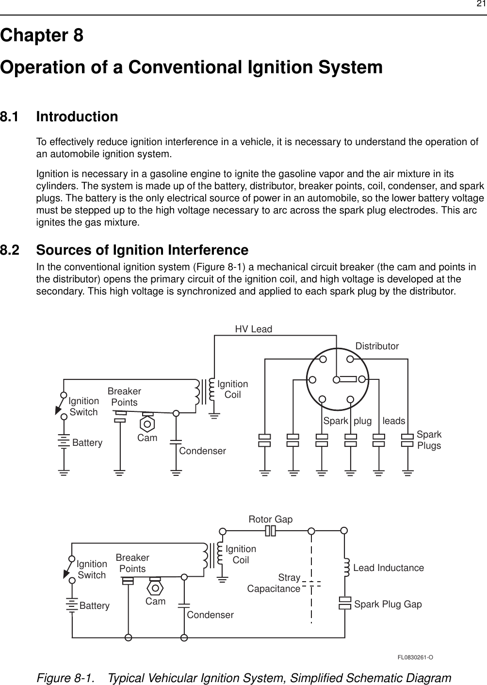
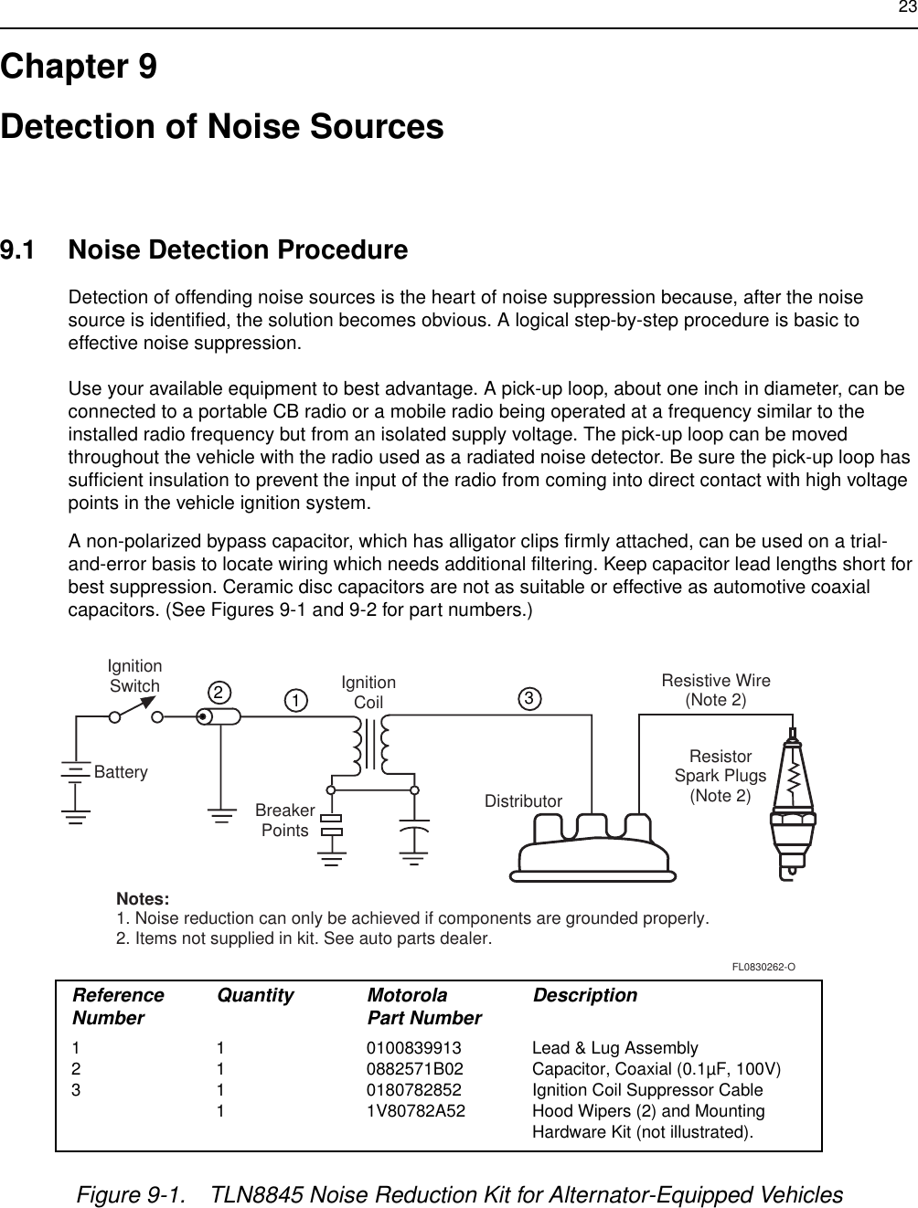
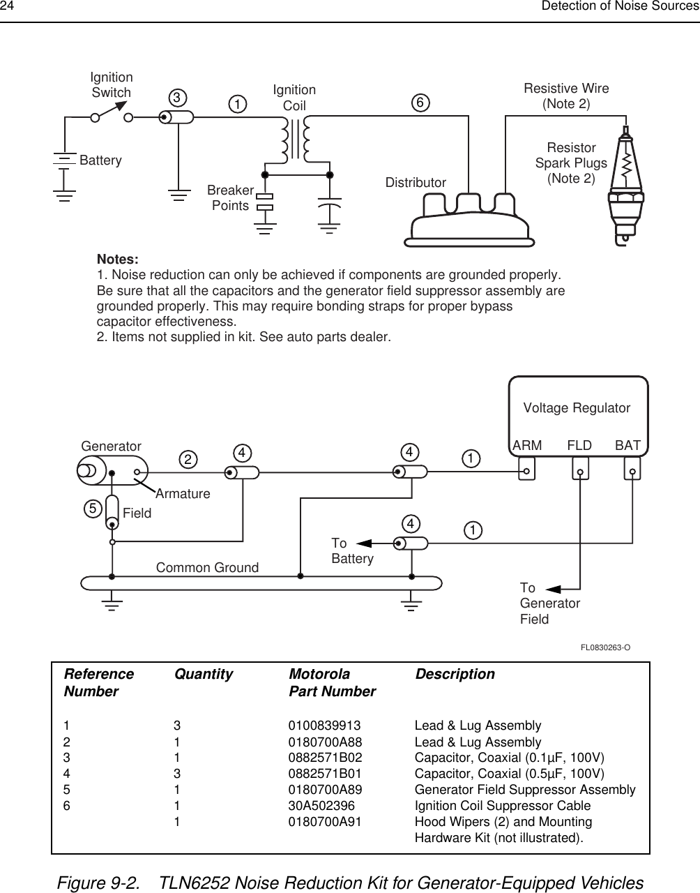
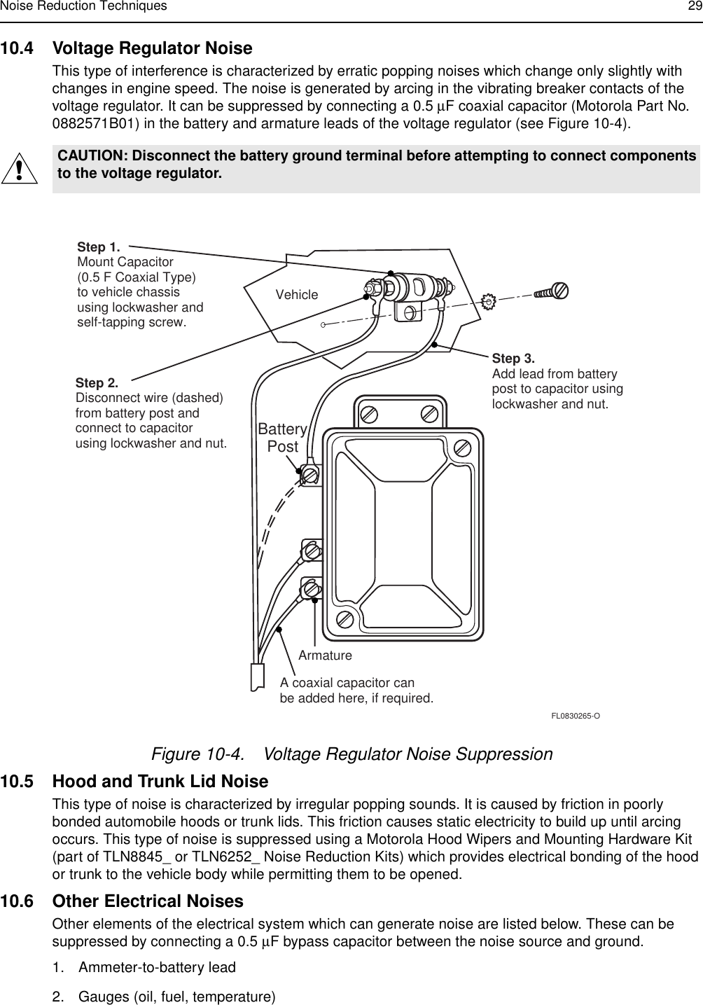
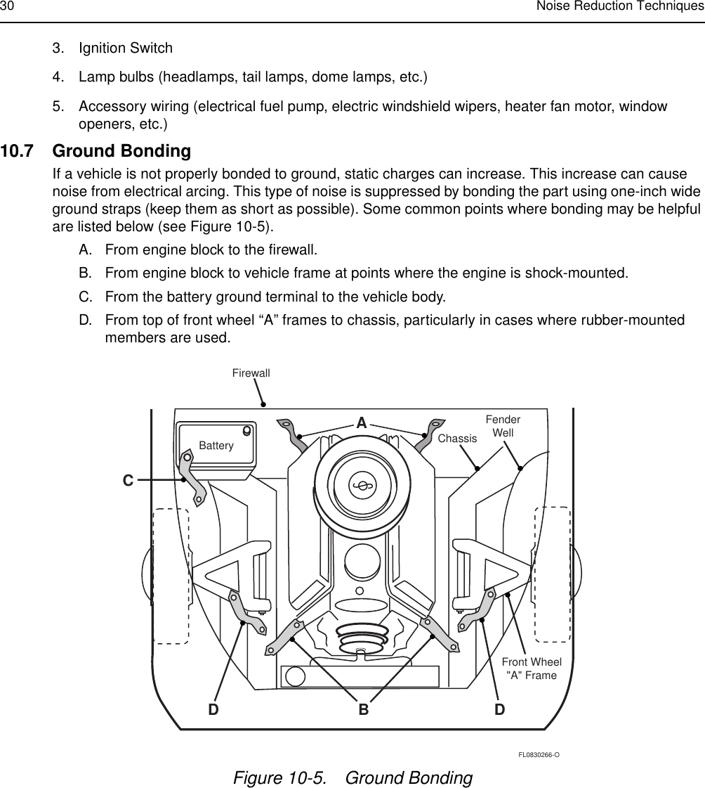
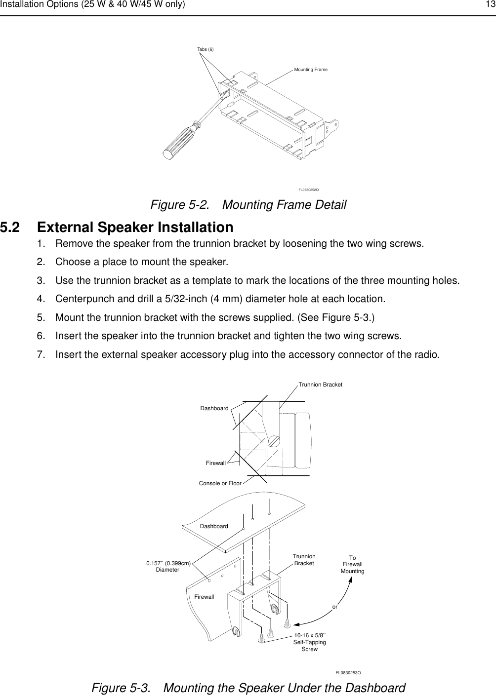
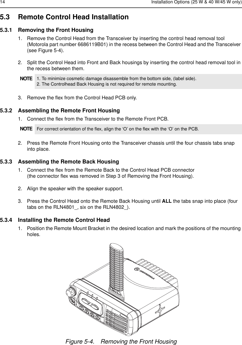
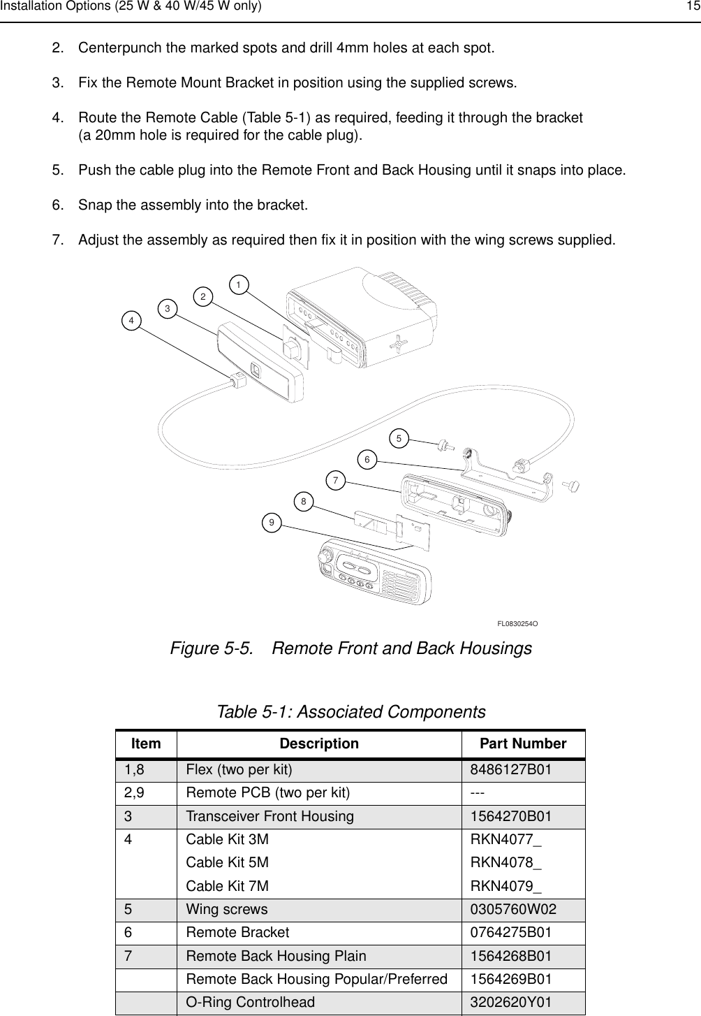
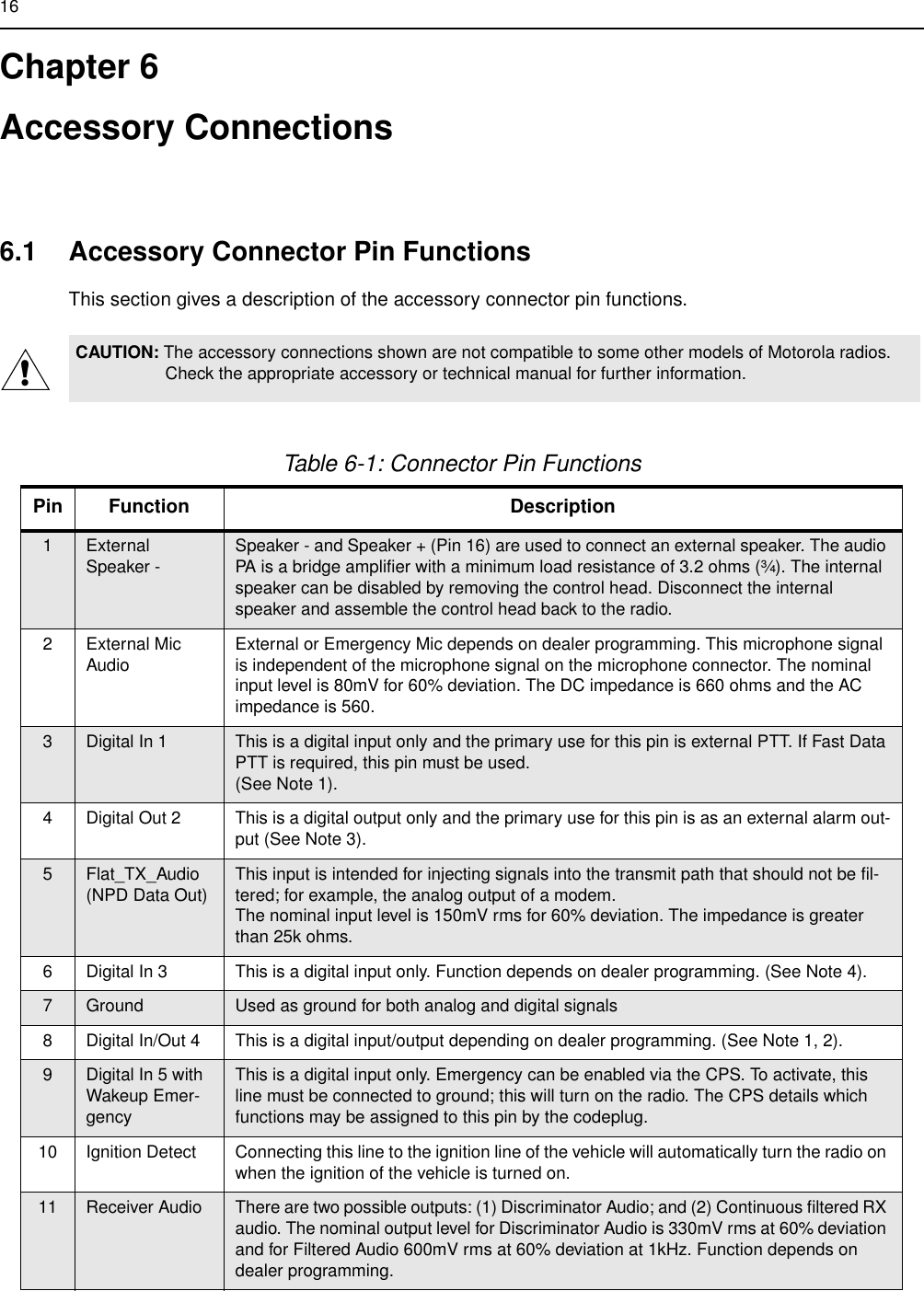
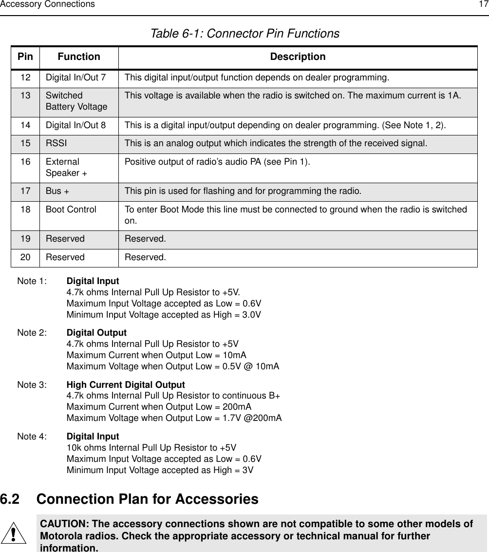
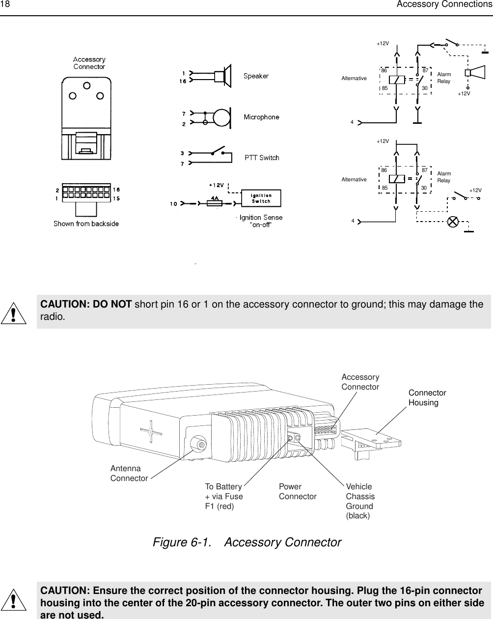
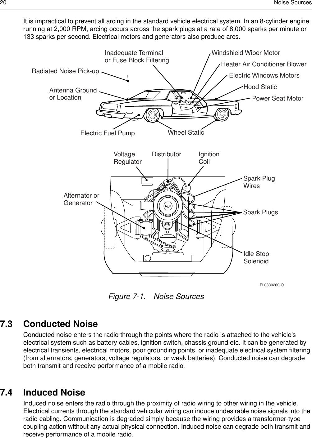
Mobile Install Manual

Installation ManualcontactcontrolProfessional RadioAs Dedicated As You Are™CA, Motorola, and Professional Radio - As Dedicated AsYou Are are trademarks of Motorola, Inc.© 1999, 2000, 2001 Motorola, Inc. All Rights Reserved.Printed In U.S.A.68P81092C58-BcontactcontrolMobile RadiosMobile Radios
iRadio InstallationTable of ContentsInformation for Vehicles with  Electronic Anti-Lock/Anti-Skid BrakesInstallation Warnings............................................................................................ivInstallation Precautions........................................................................................ivBraking System Tests ..........................................................................................ivSafety and General InformationRadio Frequency (RF) Operational Characteristics.............................................viRadio Operation and EME Exposure...................................................................viElectromagnetic Interference/Compatibility .........................................................viMedical Devices .....................................................................................viSafety and General .............................................................................................viiUse While Driving..................................................................................viiFor Vehicles With An Air Bag ................................................................viiPotentially Explosive Atmospheres .......................................................viiBlasting Caps and Areas.......................................................................viiMobile Radio Operation and EME Exposure .....................................................viiiAntenna Installation ...........................................................................................viiiMobile Antennas...................................................................................viiiFixed Site Antennas .............................................................................viiiChapter 1 Introduction1.1 General Information ............................................................................................. 11.2 Plan the Installation.............................................................................................. 1Chapter 2 DC Power Cable Installation2.1 Planning the Power Cable Installation ................................................................. 22.2 Power Cable Installation Procedure..................................................................... 2Chapter 3 Trunnion Installation3.1 Planning the Mounting Trunnion Installation........................................................ 53.1.1 Trunnion (25 W & 40 W/45 W radios)..................................................... 53.1.2 Trunnion (60 W radios)........................................................................... 53.2 25 W & 40 W/45 W Trunnion Installation Procedure ........................................... 53.3 60 W Trunnion Installation Procedure.................................................................. 73.4 Control Head Mounting Position .......................................................................... 8
iiChapter 4 Antenna Installation4.1 Mobile Radio Operation and EME Exposure......................................................104.2 Selecting an Antenna Site ..................................................................................104.3 Antenna Installation Procedure ..........................................................................114.4 Completing the Installation.................................................................................11Chapter 5 Installation Options5.1 Radio Mounting in Dashboard............................................................................125.2 External Speaker Installation..............................................................................135.3 Remote Control Head Installation.......................................................................145.3.1 Removing the Front Housing ................................................................145.3.2 Assembling the Remote Front Housing ................................................145.3.3 Assembling the Remote Back Housing.................................................145.3.4 Installing the Remote Control Head ......................................................14Chapter 6 Accessory Connections6.1 Accessory Connector Pin Functions...................................................................166.2 Connection Plan for Accessories........................................................................17Chapter 7 Noise Sources7.1 Introduction.........................................................................................................197.2 Radiated Noise...................................................................................................197.3 Conducted Noise................................................................................................207.4 Induced Noise.....................................................................................................20Chapter 8 Operation of a Conventional Ignition System8.1 Introduction.........................................................................................................218.2 Sources of Ignition Interference..........................................................................21Chapter 9 Detection of Noise Sources9.1 Noise Detection Procedure.................................................................................239.2 Sources of Noise ................................................................................................25Chapter 10 Noise Reduction Techniques10.1 General...............................................................................................................2610.2 Ignition System Interference...............................................................................2610.2.1 Engine Maintenance and Tune-Up .......................................................2610.2.2 Available Noise Reduction Kits .............................................................2610.2.3 Ignition Coil Interference.......................................................................27
iii10.2.4 Distributor Interference......................................................................... 2710.2.5 Battery Connections ............................................................................. 2710.3 Alternator/Generator Whine............................................................................... 2810.4 Voltage Regulator Noise .................................................................................... 2810.5 Hood and Trunk Lid Noise ................................................................................. 2910.6 Other Electrical Noises ...................................................................................... 2910.7 Ground Bonding................................................................................................. 30
ivInformation for Vehicles with Electronic Anti-Lock/Anti-Skid BrakesThe following installation suggestions and test procedures are recommended for vehicles with electronic anti-lock/anti-skid brakes. Refer to your vehicle service manual for your vehicle’s braking system, or contact your dealer directly.Installation WarningsDisruption of the anti-skid/anti-lock braking system by the radio transmitter may result in unexpected vehicle motion.Motorola recommends the following radio installation precautions and vehicle braking system test procedures to ensure that the radio, when transmitting, does not interfere with the operation of the vehicle braking system.Installation Precautions1. Always provide as much distance as possible between the braking modulator unit and the radio, the radio antenna, and  associated transmission line. Before installing the radio, determine the location of the brak-ing modulator unit in the vehicle. Depending on the make and model of the vehicle, the braking modulator unit may be located in the trunk, under the dashboard, in the engine compartment, or in some other cargo area. If you cannot determine the location of the braking modulator unit, refer to the vehicle service man-ual or contact a dealer for the particular make of the vehicle.2. If the braking modular unit is located on the left side of the vehicle, install the radio on the right side of the vehicle, and conversely.3. Route all radio wiring, including the antenna transmission line, as far away as possible from the braking modular unit and associated braking system wiring.4. Never activate the radio transmitter while the vehicle is in motion and the vehicle trunk lid is open.Braking System TestsBe sure the following vehicle testing is done in an isolated area. The following procedure checks for the most common types of interference that may be caused by a radio transmitter to vehicle braking system:1. Run the vehicle engine at idle speed and set the vehicle transmission selector to PARK. Release the brake pedal completely and key the radio transmitter. While NOT speaking into the microphone, verify that there are no unusual effects (visual or audible) to the vehicle lights, or other electrical equipment and accesso-ries.2. Repeat Step 1, except do so while speaking into the microphone.3. Press the vehicle brake pedal slightly; just enough to illuminate the vehicle brake light(s). Then repeat Steps 1 and 2.4. Press the vehicle brake pedal firmly and repeat Steps 1 and 2.5. Ensure that there is a minimum of two vehicle lengths between the front of the vehicle and any object in the vehicle’s forward path. Then, set the vehicle transmission selector to DRIVE. Press the brake pedal just far enough to stop the vehicle motion completely. Key the radio transmitter. Verify that the vehicle does not start to move while NOT speaking into the microphone.6. Repeat Step 5, except do so while speaking into the microphone.7. Release the brake pedal completely and accelerate the vehicle to a speed between 15 and 25 miles (25 and 40 kilometers) per hour. Ensure that a minimum of two vehicle lengths is maintained between the front of the vehicle and any object in the vehicle’s forward path. Have another person key the radio transmitter, and verify that the vehicle can be braked normally to a moderate stop while NOT speaking into the micro-phone.!WARNING
Information for Vehicles with Electronic Anti-Lock/Anti-Skid Brakes v8. Repeat Step 7, except do so while speaking into the microphone.9. Release the brake pedal completely and accelerate the vehicle to a speed of 20 miles (30 kilometers) per hour. Ensure that a minimum of two vehicle lengths is maintained between the front of the vehicle and any object in the vehicle’s forward path. Have another person key the radio transmitter, and verify that the vehi-cle can be braked properly to a sudden (panic) stop while NOT speaking into the microphone.10. Repeat Step 9, except do so while speaking into the microphone.11. Repeat Steps 9 and 10, except use a vehicle speed of 30 miles (50 kilometers) per hour.For radios installed in vehicles fuelled by liquefied petroleum gas, refer to the (U. S.) National Fire Protection Association standard, NFPA 58, for storage, handling, and/or container information.For a copy of the LP-gas standard, NFPA 58, contact the National Fire Protection Association, One Battery Park, Quincy, MA,.!WARNING
viSafety and General InformationIMPORTANT INFORMATION ON SAFE AND EFFICIENT OPERATIONREAD THIS INFORMATION BEFORE USING YOUR MOTOROLA TWO-WAY RADIOThe information provided in this document supersedes the general safety information contained in documentation published prior to June 2001. Radio Frequency (RF) Operational CharacteristicsTo transmit (talk) you must push the Push-To-Talk button; to receive (listen) you must release the Push-To-Talk button. When the radio is transmitting, it generates radio frequency (RF) energy; when it is receiving, or when it is off, it does not generate RF energy.Radio Operation and EME ExposureYour Motorola radio is designed to comply with the following national and international standards and guidelines regarding exposure of human beings to radio frequency electromagnetic energy (EME):United States Federal Communications Commission, Code of Federal Regulations; 47 CFR part 2 sub-part J American National Standards Institute (ANSI) / Institute of Electrical and Electronic Engineers (IEEE) C95. 1- 1992Institute of Electrical and Electronic Engineers (IEEE) C95.1- 1999 EditionNational Council on Radiation Protection and Measurements (NCRP) of the United States, Report 86, 1986International Commission on Non-Ionizing Radiation Protection (ICNIRP) 1998Ministry of Health (Canada) Safety Code 6. Limits of Human Exposure to Radiofrequency Electromagnetic Fields in the Frequency Range from 3 kHz to 300 GHz, 1999Australian Communications Authority Radiocommunications (Electromagnetic Radiation - Human Exposure) Standard 1999 (applicable to wireless phones only)ANATEL, Brasil Regulatory Authority, Resolução 256 (11/Abr/2001)“This equipment is in compliance with the limits of Specific Absorption Rate which refer to the exposure to electric, magnetic and electromagnetic fields adopted by ANATEL.”Electromagnetic Interference/CompatibilityMedical Devices• PacemakersThe Health Industry Manufacturers Association recommends that a minimum separation of 6 inches (15 centimeters) be maintained between a wireless radio and a pacemaker. These recommendations are consistent with those of the U.S. Food and Drug Administration.Persons with pacemakers should:ALWAYS keep their pacemaker more than 6 inches (15 cm) from the radio when the radio is turned ON.NOTE Nearly every electronic device is susceptible to electromagnetic interference (EMI) if inade-quately shielded, designed, or alternately configured for electromagnetic compatibility.
Safety and General Information vii•Hearing AidsSome digital wireless radios may interfere with some hearing aids. In the event of such interference, you may want to consult your hearing aid manufacturer to discuss alternatives.•Other Medical DevicesIf you use any other personal medical device, consult the manufacturer of your device to determine if it is adequately shielded from RF energy. Your physician may be able to assist you in obtaining this information.Safety and GeneralUse While DrivingCheck the laws and regulations on the use of the radios in the area where you drive. Always obey them.●Give full attention to driving and to the road.●Use hands-free operation, if available.●Pull off the road and park before making or answering a call if driving conditions so require.For Vehicles With An Air BagDo not place objects, including communications equipment, in the area over an air bag or in the air bag deployment area. Air bags inflate with great force. If a radio is in the air bag deployment area and the air bag inflates, the radio may be propelled with great force and cause serious injury to occupants of the vehicle.Potentially Explosive AtmospheresTurn off your radio prior to entering any area with a potentially explosive atmosphere, unless it is a radio type especially qualified for use in such areas as “Intrinsically Safe” (for example, Factory Mutual, CSA, UL, or CENELEC). Do not remove, install, or charge batteries in such areas. Sparks in a potentially explosive atmosphere can cause an explosion or fire resulting in bodily injury or even death.Blasting Caps and AreasTo avoid possible interference with blasting operations, turn off your radio when you are near electrical blasting caps, in a blasting area, or in areas posted: “Turn off two-way radio.” Obey all signs and instructions.NOTE The areas with potentially explosive atmospheres referred to above include fuelling areas such as: below decks on boats; fuel or chemical transfer or storage facilities; areas where the air contains chemicals or particles, such as grain, dust or metal powders; and any other area where you would normally be advised to turn off your vehicle engine. Areas with potentially explosive atmospheres are often but not always posted.!OPERATIONAL WARNINGS
viii Safety and General InformationMobile Radio Operation and EME ExposureTo assure optimal radio performance and that human exposure to radio frequency electromagnetic energy is within the guidelines referenced in this document, transmit only when people outside the vehicle are at least the minimum lateral distance away from a properly installed, externally-mounted antenna.The table below lists the minimum and lateral distance for several different ranges of rated radio power.Antenna InstallationMobile AntennasRecommended mobile antenna installations are limited to metal body vehicles at the center of the roof and center of the trunk deck locations.Install the vehicle antenna external to the vehicle in accordance with the requirements of the antenna manufacturer/supplier.Fixed Site AntennasMobile radio equipment is sometimes installed at a fixed location and operated as a control station or as a fixed unit. In such cases the antenna installation must comply with the following requirements in order to assure optimal performance and make sure human exposure to radio frequency electromagnetic energy is within the guidelines set forth in the above standards.●The antenna must be mounted outside the building.●Mount the antenna on a tower if at all possible.●If the antenna is to be mounted on a building then it must be mounted on the roof.●As with all fixed site antenna installations, it is the responsibility of the licensee to manage the site in accordance with applicable regulatory requirements and may require additional compliance actions such as site survey measurements, signage, and site access restrictions in order to insure that exposure limits are not exceeded.Rated Power of Vehicle-Installed Mobile Two-Way Radio Minimum Distance from Transmitting AntennaLess than 7 Watts 8 Inches (20 Centimeters)7 to 15 Watts 1 Foot (30.5 Centimeters)16 to 50 Watts 2 Feet (60 Centimeters)More than 50 Watts 3 Feet (90 Centimeters)
1Chapter 1Introduction1.1 General InformationThere are two methods of installing your mobile radio:1. The standard radio package contains a direct mounting trunnion and power cables.2. Some models may be mounted in the car radio cut-out (using the required RLN4781_ mounting kit).An accessory connector on the rear of the radio (see Figure 4-1) enables you to attach different accessories required for the installation.A ten-pin telephone type connector on the front control head panel (see Figure 3-1) provides for the connection of various types of microphones.1.2 Plan the Installation1. Mount the radio horizontally near the driver, so the driver can easily view, access, and operate the controls and accessories.2. Ensure that the location is not exposed to dirt and moisture.3. Verify that there will be sufficient space around the mobile unit for air flow and installation.4. Check that there is enough routing space for the power cable connector and the antenna coaxial cable.5. Plan the best place to run connections to minimize chafing, pinching, crushing, and overheating of wires and cables.NOTE In a vehicle with an airbag, make sure that the mounting location of the mobile radio, or any radio accessory, is not in the deployment path of the air bag.
2Chapter 2DC Power Cable Installation2.1 Planning the Power Cable InstallationThe 10 foot (3 m) DC power cable shipped with the radio should be long enough to be installed in most vehicles. Take the following precautions before you begin:●Whenever possible, avoid routing the cable above the catalytic converter. ●Use grommets whenever a cable has to pass through a hole in a metal panel. The following table lists power cables available for this radio:2.2 Power Cable Installation ProcedureBegin the power cable installation as follows:1. Determine a routing plan, keeping in mind where the radio is to be mounted.2. Locate an existing hole with grommet in the vehicle fire wall, or use a 3/8-inch (9.5 mm) bit to drill an access hole in the fire wall. Install a grommet with a 3/16-inch (4.9 mm) inside diameter into the hole to protect the power cable.3. From inside the vehicle, feed the red and black leads (without the lugs attached) through the access hole and into the engine compartment. (See Figure 2-1.)CAUTION: This radio must be operated only in negative ground electrical systems. Operating the radio on a positive ground system will cause the cable fuse to short-circuit. Check the vehicle ground polarity before you begin the installation.Table 2-1: Power CablesNumber Description RatingHKN4137_ 12V Low power cable to battery 1-25W; 15A fuse; 14 AWG 3m HKN4191_ High Power cable to battery 1-60W; 20A fuse; 12 AWG 3mHKN4192_ 12V Power cable to battery 1-60W; 20A fuse; 10 AWG 6mCAUTION: Improper handling with the power cable may short to ground. Ensure that during radio installation the power cable fuse is removed.CAUTION: Be very careful not to damage existing wires.!!!
DC Power Cable Installation 34. Connect the black lead of the power cable to the nearest vehicle chassis ground point, which is usually the central ground point near the battery (using the provided ring lug if necessary). Shorten the black lead to remove any excess cable. (See Figure 2-2.)5. Place the fuse holder close to the battery. Ensure that it is not near any hot engine component. Mount the fuse holder using its mounting hole and dress the wires as required. 6. Insert the stripped end of the red lead of the fuse holder into the ring lug hole and crimp it. Connect the fuse holder red adapter lead plug to the mating receptacle on the red lead of the power cable. (See Figure 2-2.)7. Connect the power cable black lead directly to the vehicle chassis ground. 8. Connect the red lead ring lug from the fuse holder to the positive (+) battery terminal. Make sure the adapter cable is connected to the main power cable red lead.9. Carefully check that all connections are proper. Insert the fuse into the fuse holder and close the cover. (See Figure 2-2.)Figure 2-1. Power Cable Routing into the Engine CompartmentNOTE Locate a good vehicle ground point. The vehicle central ground point provides the best ground. If this is not available, the vehicle frame provides the best ground. Optimum radio performance can only be achieved with a very low resistance ground connection. Verify that the connections between the battery negative terminal, vehicle chassis, and engine block have low resistance.NOTE Failure to mount the red lead of the power cable kit directly to the battery may result in severe alternator whine interference. Black LeadRed LeadFirewallGrommetEngine CompartmentTo RadioFL08302460
4DC Power Cable InstallationFigure 2-2. Power Cable AssemblyFuseCoverRed LeadRed LeadMountingHoleMolded In-LineFuse HolderTo VehicleChassis GroundEngineCompartment To Battery (+)AdapterFirewallRed LeadBlack LeadRingLugsFL08302470
5Chapter 3Trunnion Installation3.1 Planning the Mounting Trunnion Installation3.1.1 Trunnion (25 W & 40 W/45 W radios)The mounting trunnion for a 25 W & 40 W/45 W radio allows the radio to be mounted to a variety of surfaces.1. Ensure the surface can support the weight of the radio.2. Although the mounting trunnion can be mounted to a plastic dashboard, it is recommended that the mounting screws be located so they penetrate the supporting metal frame of the dashboard.3.1.2 Trunnion (60 W radios)The mounting trunnion for a 60 W radio allows the radio to be mounted for a transmission hump. It is recommended that a 60 W radio be mounted only on the transmission hump.3.2 25 W & 40 W/45 W Trunnion Installation Procedure1. Select either the transmission hump or an open underneath portion of the dash to mount your radio. (See Figure 3-1.) When mounting the trunnion on the transmission hump, be careful that the transmission housing is not affected.2. Use the trunnion mounting bracket as a template to mark the hole positions on the mounting surface. Use the innermost three holes for a curved mounting surface, such as the transmission hump, and the three outermost holes for a flat surface such as under the dash.3. Center-punch the spots you marked and use a 5/32-inch (4 mm) bit to drill a hole at each location.4. Secure the trunnion mounting bracket to the mounting surface with the three self-tapping screws provided. (See Figure 3-1.)5. Slide the radio into the trunnion. Secure the radio with the two M5 thumb screws provided. (See Figure 3-2.)
6Trunnion InstallationFigure 3-1. 25 W & 40 W/45 W Transmission Hump Mounting (Top) and Below Dash Mounting (Bottom)TabBELOW DASH MOUNTINGMounting SurfaceMountingSurfaceTabThumb Screw(2)TRANSMISSION HUMP MOUNTINGTabThumb Screw(2)Sheet MetalScrewsTrunnion MountingBracketTrunnion Mounting BracketFL0830250O 1.84"(46mm)2.92"(73mm) 2.92"(73mm)1.84"(46mm)1.12"(28mm)
Trunnion Installation 73.3 60 W Trunnion Installation Procedure1. Use the trunnion mounting bracket as a template to mark the hole positions on the mounting surface. Use the five holes for a curved mounting surface. (See Figure 3-3.) Be careful that the transmission housing is not affected.Figure 3-2. 25 W & 40 W/45 W Radio into TrunnionFigure 3-3. 60 W Radio Transmission Hump MountingThumbScrewThumbScrewTrunnion FL0830248OFL0830814O
8Trunnion Installation2. Center punch the spots you have marked and drill a 5/32" (4 mm) hole at each location.3. Secure the trunnion mounting bracket to the surface with the five 10-16x3/4" (20 mm) screws provided.4. Slide the radio in the trunnion. Secure the radio with the two M5 thumb screws provided and one TT5 rear screw. (See Figure 3-4.)3.4 Control Head Mounting PositionThe control head is designed to be removed from the housing and rotated 180 degrees. This provides multiple mounting options for the radio. For example, the radio may be mounted on either side of the vehicle transmission tunnel to facilitate the safest and most ergonomically ideal position. The control head may then be turned to provide the most convenient access.To reposition the control head:1. Insert the control head removal tool (Motorola part number 6686119B01) in the recess between the control head and the radio housing. (See Figure 5-4,  on page 5-14.)2. Press until the control head releases.3. Pull the control head away while ensuring that the flex connector remains attached.Figure 3-4. 60 W Radio Being Placed onto a TrunnionFL0830815OMicrophoneConnector
Trunnion Installation 94. Rotate the control head, and fold the flex circuit to align it to the new position.5. Push the control head into the housing until the protruding tabs snap into place.CAUTION: The contact surface of the flex circuit should be facing the printed circuit board.!
10Chapter 4Antenna Installation4.1 Mobile Radio Operation and EME ExposureObserve the following caution and electromagnetic energy exposure (EME) statements wheninstalling antennas:Read the Mobile Radio Operation and EME exposure section on page viii before proceeding with theinstallation.4.2 Selecting an Antenna Site1. Install the vehicle antenna external to the vehicle in accordance with the requirements of theantenna manufacturer/supplier.2. The best mounting location for the antenna is in the center of a large, flat conductive surface. Inalmost all vehicles, mounting the antenna in the center of the roof will satisfy these requirements.A good alternate location is in the center of the trunk lid (check the requirements of the antennamanufacturer/supplier before mounting the antenna to the trunk lid). If you use the trunk lid,ensure that the trunk lid is grounded by connecting grounding straps between the trunk lid and thevehicle chassis.3. Ensure the antenna cable can be easily routed to the radio. Ensure that the antenna cable isrouted separately and not in parallel to any other vehicle wiring or mobile radio cable wiring.4. Check the antenna location for any electrical interference.5. If the vehicle is equipped with an electronic anti-lock braking system (ABS), and the antenna willbe trunked mounted, then install the antenna on the side opposite to the braking modulator box.This minimizes radio interference to the modulator box from the radio.6. Make sure the mobile radio antenna is installed at least one foot (30.48 cm) away from any otherantenna on the vehicle.CAUTION: Use caution when installing antennas with mobile radio equipment usingtransmitter power in excess of 7 Watts.NOTE For low-power mobile radios (7 Watts, or less), there are no antenna type orinstallation restrictions.NOTE Any two metal pieces rubbing against each other (such as seat springs, shift levers,trunk and hood lids, exhaust pipes, etc.) in close proximity to the antenna can causesevere receiver interference.!
Antenna Installation 114.3 Antenna Installation Procedure1. Mount the antenna according to the instructions provided with the antenna kit. Run the coaxialcable to the radio mounting location. If necessary, cut off the excess cable and install the cableconnector.2. Connect the antenna cable connector to the radio antenna connector on the rear of the radio.(See Figure 4-1.)4.4 Completing the Installation1. Mount the microphone clip to a convenient spot near your radio.2. Your microphone has a telephone-type connector at the end of its cord. Plug the microphone intothe control head connector.3. To complete your radio installation, plug the power cable into the radio power connector. (SeeFigure 4-1.)Figure 4-1. Connections to the Back of RadioAntenna Connector To Battery+ via FuseF1 (red)PowerConnector VehicleChassisGround(black)AccessoryConnector ConnectorHousingFL0830249O
12Chapter 5Installation Options (25 W & 40 W/45 W only)5.1 Radio Mounting in DashboardTo install the radio in an automotive dashboard:1. Open the radio cutout in the dashboard and, if necessary, enlarge it to the dimensions shown in Figure 5-1.2. Insert the mounting frame into the cutout and bend the six tabs (see Figure 5-2) to hold it in place. Press the bezel onto the mounting frame. 3. Slide the radio into the mounting frame.4. Make the necessary connections to the radio for power, antenna, and accessory connector as shown in Figure 4-1.Figure 5-1. Mounting the radio into the dashboard BezelMountingFrame175mm180mm52mmFL08302510(7-1/4")(7")(2")
Installation Options (25 W & 40 W/45 W only) 135.2 External Speaker Installation1. Remove the speaker from the trunnion bracket by loosening the two wing screws. 2. Choose a place to mount the speaker.3. Use the trunnion bracket as a template to mark the locations of the three mounting holes.4. Centerpunch and drill a 5/32-inch (4 mm) diameter hole at each location.5. Mount the trunnion bracket with the screws supplied. (See Figure 5-3.)6. Insert the speaker into the trunnion bracket and tighten the two wing screws.7. Insert the external speaker accessory plug into the accessory connector of the radio.Figure 5-2. Mounting Frame DetailFigure 5-3. Mounting the Speaker Under the DashboardTabs (6)Mounting FrameFL0830252ODashboardFirewallTrunnion BracketToFirewallMountingorDashboardFirewall10-16 x 5/8’’Self-TappingScrew0.157’’ (0.399cm)Diameter TrunnionBracketConsole or FloorFL0830253O
14 Installation Options (25 W & 40 W/45 W only)5.3 Remote Control Head Installation5.3.1 Removing the Front Housing1. Remove the Control Head from the Transceiver by inserting the control head removal tool (Motorola part number 6686119B01) in the recess between the Control Head and the Transceiver (see Figure 5-4).2. Split the Control Head into Front and Back housings by inserting the control head removal tool in the recess between them.3. Remove the flex from the Control Head PCB only.5.3.2 Assembling the Remote Front Housing1. Connect the flex from the Transceiver to the Remote Front PCB.2. Press the Remote Front Housing onto the Transceiver chassis until the four chassis tabs snap into place.5.3.3 Assembling the Remote Back Housing1. Connect the flex from the Remote Back to the Control Head PCB connector (the connector flex was removed in Step 3 of Removing the Front Housing).2. Align the speaker with the speaker support.3. Press the Control Head onto the Remote Back Housing until ALL the tabs snap into place (four tabs on the RLN4801_, six on the RLN4802_).5.3.4 Installing the Remote Control Head1. Position the Remote Mount Bracket in the desired location and mark the positions of the mounting holes.NOTE 1. To minimize cosmetic damage disassemble from the bottom side, (label side).2. The Controlhead Back Housing is not required for remote mounting.NOTE For correct orientation of the flex, align the ‘O’ on the flex with the ‘O’ on the PCB.Figure 5-4. Removing the Front Housing
Installation Options (25 W & 40 W/45 W only) 152. Centerpunch the marked spots and drill 4mm holes at each spot.3. Fix the Remote Mount Bracket in position using the supplied screws.4. Route the Remote Cable (Table 5-1) as required, feeding it through the bracket (a 20mm hole is required for the cable plug).5. Push the cable plug into the Remote Front and Back Housing until it snaps into place.6. Snap the assembly into the bracket.7. Adjust the assembly as required then fix it in position with the wing screws supplied.Figure 5-5. Remote Front and Back HousingsTable 5-1: Associated ComponentsItem Description Part Number1,8 Flex (two per kit) 8486127B012,9 Remote PCB (two per kit)  --- 3Transceiver Front Housing 1564270B014 Cable Kit 3MCable Kit 5MCable Kit 7MRKN4077_RKN4078_RKN4079_5Wing screws 0305760W026 Remote Bracket 0764275B017Remote Back Housing Plain 1564268B01Remote Back Housing Popular/Preferred 1564269B01O-Ring Controlhead 3202620Y01123457896FL0830254O
16Chapter 6Accessory Connections6.1 Accessory Connector Pin FunctionsThis section gives a description of the accessory connector pin functions.CAUTION: The accessory connections shown are not compatible to some other models of Motorola radios. Check the appropriate accessory or technical manual for further information.Table 6-1: Connector Pin FunctionsPin Function Description1External Speaker - Speaker - and Speaker + (Pin 16) are used to connect an external speaker. The audio PA is a bridge amplifier with a minimum load resistance of 3.2 ohms (¾). The internal speaker can be disabled by removing the control head. Disconnect the internal speaker and assemble the control head back to the radio.2External Mic Audio External or Emergency Mic depends on dealer programming. This microphone signal is independent of the microphone signal on the microphone connector. The nominal input level is 80mV for 60% deviation. The DC impedance is 660 ohms and the AC impedance is 560.3Digital In 1 This is a digital input only and the primary use for this pin is external PTT. If Fast Data PTT is required, this pin must be used.(See Note 1).4 Digital Out 2 This is a digital output only and the primary use for this pin is as an external alarm out-put (See Note 3).5Flat_TX_Audio (NPD Data Out) This input is intended for injecting signals into the transmit path that should not be fil-tered; for example, the analog output of a modem.The nominal input level is 150mV rms for 60% deviation. The impedance is greater than 25k ohms.6 Digital In 3 This is a digital input only. Function depends on dealer programming. (See Note 4).7Ground Used as ground for both analog and digital signals8 Digital In/Out 4 This is a digital input/output depending on dealer programming. (See Note 1, 2).9Digital In 5 with Wakeup Emer-gencyThis is a digital input only. Emergency can be enabled via the CPS. To activate, this line must be connected to ground; this will turn on the radio. The CPS details which functions may be assigned to this pin by the codeplug.10 Ignition Detect Connecting this line to the ignition line of the vehicle will automatically turn the radio on when the ignition of the vehicle is turned on.11 Receiver Audio There are two possible outputs: (1) Discriminator Audio; and (2) Continuous filtered RX audio. The nominal output level for Discriminator Audio is 330mV rms at 60% deviation and for Filtered Audio 600mV rms at 60% deviation at 1kHz. Function depends on dealer programming. !
Accessory Connections 176.2 Connection Plan for Accessories12 Digital In/Out 7 This digital input/output function depends on dealer programming.13 Switched Battery Voltage This voltage is available when the radio is switched on. The maximum current is 1A.14 Digital In/Out 8 This is a digital input/output depending on dealer programming. (See Note 1, 2).15 RSSI This is an analog output which indicates the strength of the received signal.16 External Speaker + Positive output of radio’s audio PA (see Pin 1).17 Bus + This pin is used for flashing and for programming the radio.18 Boot Control To enter Boot Mode this line must be connected to ground when the radio is switched on.19 Reserved Reserved.20 Reserved Reserved.Note 1:  Digital Input4.7k ohms Internal Pull Up Resistor to +5V. Maximum Input Voltage accepted as Low = 0.6V Minimum Input Voltage accepted as High = 3.0VNote 2:  Digital Output4.7k ohms Internal Pull Up Resistor to +5VMaximum Current when Output Low = 10mAMaximum Voltage when Output Low = 0.5V @ 10mANote 3:  High Current Digital Output4.7k ohms Internal Pull Up Resistor to continuous B+Maximum Current when Output Low = 200mAMaximum Voltage when Output Low = 1.7V @200mANote 4:  Digital Input10k ohms Internal Pull Up Resistor to +5VMaximum Input Voltage accepted as Low = 0.6VMinimum Input Voltage accepted as High = 3VCAUTION: The accessory connections shown are not compatible to some other models of Motorola radios. Check the appropriate accessory or technical manual for further information.Table 6-1: Connector Pin FunctionsPin Function Description!
18 Accessory ConnectionsCAUTION: DO NOT short pin 16 or 1 on the accessory connector to ground; this may damage the radio.Figure 6-1. Accessory ConnectorCAUTION: Ensure the correct position of the connector housing. Plug the 16-pin connector housing into the center of the 20-pin accessory connector. The outer two pins on either side are not used.48685 +12V+12V48685AlternativeAlternativeAlarmRelayAlarmRelay87873030+12V+12V!Antenna Connector To Battery+ via FuseF1 (red)PowerConnector VehicleChassisGround(black)AccessoryConnector ConnectorHousing!
19Chapter 7Noise Sources7.1 IntroductionElectrical noise generated by the electrical system of a vehicle, as well as local ambient noise, caninterfere with normal operation of mobile radios. Satisfactory operation of a mobile radio may requireslight or heavy noise reduction, depending upon the relative strength of the radio signal, and upon theability of the radio to reject undesired noise. These requirements vary from one vehicle to another,depending upon the vehicle type and required coverage area. When operating in a strong signal area,a certain amount of noise interference can be tolerated. In weak signal areas, however, noisereduction becomes very important. As a rule of thumb, noise levels create greatest interference in the25-50MHz band and reduce with increasing frequency.Before attempting any noise reduction procedures, determine the noise source(s). Then, follow alogical, systematic method of elimination until the interference is eliminated or reduced to anacceptable level.Care and patience must be exercised in locating and eliminating noise sources. There may be severalsources of noise, each slightly stronger or weaker than the other. Elimination of one source may seemineffective because another noise source remains active at a barely discernible difference in level.Consult a service manual for the vehicle to determine what noise reduction provisions themanufacturer applies when AM, AM/FM, or CB radios are installed as original equipment. Theseradios are also subject to electrical noise interference, and the manufacturer may install noisesuppression components only upon those vehicles which require radio equipment at the time ofmanufacture. These noise suppression components should be added in any first attempt to suppressnoise.The three major noise sources affecting mobile radio systems are: (1) radiated noise, (2) conductednoise, and (3) induced noise. (See Figure 7-1 for typical vehicular noise sources.)7.2 Radiated NoiseRadiated noise enters the radio through the antenna along with the desired signal and can block ordegrade desired communication. It can be generated by power lines, fluorescent lights, or byelectrical discharges from static build-up, ignition systems, or electrical motors. Radiated noise is themost common cause of mobile radio interference.When a spark discharge or arc takes place through air, energy is radiated at frequencies from a fewkilohertz to hundreds of megahertz. This spurious radiation may have some energy radiated at afrequency near or even identical to the desired radio signal. The standard receiver may be unable todistinguish between the two signals (desired and noise). Therefore they both enter the receiver,resulting in degradation of the desired signal.CAUTION: Do not add interference elimination equipment to vehicles equipped withelectronic ignition systems before obtaining advice from the vehicle manufacturer. Additionof some noise suppression components may interfere with proper operation of electronicignition systems and could seriously damage them.!
20 Noise SourcesIt is impractical to prevent all arcing in the standard vehicle electrical system. In an 8-cylinder enginerunning at 2,000 RPM, arcing occurs across the spark plugs at a rate of 8,000 sparks per minute or133 sparks per second. Electrical motors and generators also produce arcs.7.3 Conducted NoiseConducted noise enters the radio through the points where the radio is attached to the vehicle’selectrical system such as battery cables, ignition switch, chassis ground etc. It can be generated byelectrical transients, electrical motors, poor grounding points, or inadequate electrical system filtering(from alternators, generators, voltage regulators, or weak batteries). Conducted noise can degradeboth transmit and receive performance of a mobile radio.7.4 Induced NoiseInduced noise enters the radio through the proximity of radio wiring to other wiring in the vehicle.Electrical currents through the standard vehicular wiring can induce undesirable noise signals into theradio cabling. Communication is degraded simply because the wiring provides a transformer-typecoupling action without any actual physical connection. Induced noise can degrade both transmit andreceive performance of a mobile radio.Figure 7-1. Noise SourcesSpark PlugsIdle StopSolenoidFL0830260-OSpark PlugWiresAlternator orGeneratorVoltageRegulator Distributor IgnitionCoilWheel StaticElectric Fuel PumpAntenna Groundor LocationRadiated Noise Pick-upInadequate Terminalor Fuse Block Filtering Windshield Wiper MotorHeater Air Conditioner BlowerElectric Windows MotorsHood StaticPower Seat Motor
21Chapter 8Operation of a Conventional Ignition System8.1 IntroductionTo effectively reduce ignition interference in a vehicle, it is necessary to understand the operation of an automobile ignition system.Ignition is necessary in a gasoline engine to ignite the gasoline vapor and the air mixture in its cylinders. The system is made up of the battery, distributor, breaker points, coil, condenser, and spark plugs. The battery is the only electrical source of power in an automobile, so the lower battery voltage must be stepped up to the high voltage necessary to arc across the spark plug electrodes. This arc ignites the gas mixture.8.2 Sources of Ignition Interference In the conventional ignition system (Figure 8-1) a mechanical circuit breaker (the cam and points in the distributor) opens the primary circuit of the ignition coil, and high voltage is developed at the secondary. This high voltage is synchronized and applied to each spark plug by the distributor.Figure 8-1. Typical Vehicular Ignition System, Simplified Schematic Diagram HV LeadDistributorSpark  plug    leadsSparkPlugsIgnitionCoilCondenserCamBreakerPointsIgnitionSwitchBatteryIgnitionCoilCondenserStrayCapacitanceCamBreakerPointsIgnitionSwitchBatteryRotor GapLead InductanceSpark Plug GapFL0830261-O
22 Operation of a Conventional Ignition SystemThe battery is connected to the primary winding of the coil through the ignition switch. The primary circuit is returned to the battery through the breaker points, which are bypassed by the condenser. The points are normally closed. As the cam shaft is rotated by the engine, its lobes or corners open and close the points in proper synchronization with the piston in each cylinder.With the ignition switch on and the breaker points closed, coil primary current builds up at a rate determined by the coil inductance.When the breaker points open, primary current decreases and, by self-induction, an electromotive force is induced in the primary which is many times greater than the battery voltage. The high voltage inducted in the coil secondary causes a spark across the distributor rotor-to-spark plug wire gap and then across the spark plug gap for a short interval of time when the breaker points open. The condenser reduces arcing of the points.The secondary circuit of the ignition coil, including the distributor rotor gap and the spark gap, is the main source of ignition interference. The lead inductance and stray capacitance provide a tuned circuit. Because the discharge of the circuit is through a low resistance (ionized spark gap), the circuit tends to oscillate. The frequency and amplitude of oscillation vary as current changes in the spark gap.
23Chapter 9Detection of Noise Sources9.1 Noise Detection ProcedureDetection of offending noise sources is the heart of noise suppression because, after the noise source is identified, the solution becomes obvious. A logical step-by-step procedure is basic to effective noise suppression.Use your available equipment to best advantage. A pick-up loop, about one inch in diameter, can be connected to a portable CB radio or a mobile radio being operated at a frequency similar to the installed radio frequency but from an isolated supply voltage. The pick-up loop can be moved throughout the vehicle with the radio used as a radiated noise detector. Be sure the pick-up loop has sufficient insulation to prevent the input of the radio from coming into direct contact with high voltage points in the vehicle ignition system.A non-polarized bypass capacitor, which has alligator clips firmly attached, can be used on a trial-and-error basis to locate wiring which needs additional filtering. Keep capacitor lead lengths short for best suppression. Ceramic disc capacitors are not as suitable or effective as automotive coaxial capacitors. (See Figures 9-1 and 9-2 for part numbers.)Figure 9-1. TLN8845 Noise Reduction Kit for Alternator-Equipped VehiclesIgnitionSwitchBatteryIgnitionCoilDistributorBreakerPointsResistive Wire(Note 2)ResistorSpark Plugs(Note 2)Notes:1. Noise reduction can only be achieved if components are grounded properly.2. Items not supplied in kit. See auto parts dealer.123FL0830262-OReference Quantity Motorola DescriptionNumber Part Number1 1 0100839913 Lead & Lug Assembly2 1 0882571B02 Capacitor, Coaxial (0.1µF, 100V)3 1 0180782852 Ignition Coil Suppressor Cable1 1V80782A52 Hood Wipers (2) and Mounting Hardware Kit (not illustrated).
24 Detection of Noise SourcesFigure 9-2. TLN6252 Noise Reduction Kit for Generator-Equipped VehiclesGeneratorIgnitionSwitchBatteryIgnitionCoilDistributorBreakerPointsResistive Wire(Note 2)ResistorSpark Plugs(Note 2)ArmatureFieldCommon GroundToBatteryToGeneratorFieldVoltage RegulatorARM FLD BATNotes:1. Noise reduction can only be achieved if components are grounded properly.Be sure that all the capacitors and the generator field suppressor assembly aregrounded properly. This may require bonding straps for proper bypasscapacitor effectiveness.2. Items not supplied in kit. See auto parts dealer.FL0830263-O1234561414Reference Quantity Motorola DescriptionNumber Part Number1 3 0100839913 Lead & Lug Assembly2 1 0180700A88 Lead & Lug Assembly3 1 0882571B02 Capacitor, Coaxial (0.1µF, 100V)4 3 0882571B01 Capacitor, Coaxial (0.5µF, 100V)5 1 0180700A89 Generator Field Suppressor Assembly6 1 30A502396 Ignition Coil Suppressor Cable1 0180700A91 Hood Wipers (2) and Mounting Hardware Kit (not illustrated).
Detection of Noise Sources 259.2 Sources of NoiseSome interference is due to geographic location. This interference does not need to be eliminated since it is possible for the vehicle to be moved away from the interfering noise source. Noise from power lines, fluorescent lights, and other vehicles (emitting high levels of radiated noise) are examples of noise which depends upon location. Make certain that you are not attempting to suppress noise in a vehicle while it is in a noisy location. If you suspect that your location is noisy, simply turn off everything in the vehicle except the radio and listen to the remaining ambient noise. If the noise level is objectionable, you may have to noise suppress the vehicle during a less noisy time of day or in a different, quieter location.Check the installed radio for conducted and inducted noise by using an unmodulated signal generator to supply a clean RF signal through a coaxial cable directly to the antenna connector on the radio set. This should prevent radiated noise from entering the receiver and masking conducted and induced noise. Make certain that the signal generator is not microphonic and is placed away from the noise of the engine and exhaust. Operate the controls for fans, blowers, power windows, headlamps, turn signals, windshield wipers, and other electrical accessories. Listen for the presence of noise in the received radio signal. This will allow the source of the interference to be determined. Some noise sources cannot be turned on and off at will. These sources will need to be attacked piecemeal on a trial and error basis: alternator whine, voltage regulators, electric fuel pump, and other possible sources. Remember that induced noise can result from radio wiring being too close to other vehicle wiring. This problem is most easily solved by proper cable routing at the time of installation.Radiated noise must be attacked after conducted and induced noise has been satisfactorily suppressed. The vehicle ignition system is usually the primary source of this interference. Antenna placement can be critical in some installations. Remember that static discharge generates static or radiated noise and will probably be generated only when the vehicle is in motion.Since radiated noise interference is most noticeable in weak signal areas, it is suggested that suppression be finalized while listening to a weak “on frequency” signal. (The squelch should be “open” so that even marginal signals can be heard.)
26Chapter 10Noise Reduction Techniques10.1 GeneralThere are three basic ways to suppress noise. The first is the addition of resistance in circuits subject to ringing. This method is used for the ignition coil HV cable, spark plug wires, and spark plugs. The second is to filter noise from low voltage wiring using coaxial bypass capacitors. The third is to control static charge build-up using wipers for movable parts such as automobile hoods and trunk lids, or flexible bonding leads for fixed members. Static in wheels may also be controlled using collector rings. Applications of each of these techniques are discussed below.The vehicle manufacturer’s service manual may also provide noise suppression information which is valuable in any first attempt at noise suppression.10.2 Ignition System Interference10.2.1 Engine Maintenance and Tune-UpThe most important step in reducing ignition noise is ensuring that the engine is in proper tune. Pay particular attention to the following points if the noise interference from the ignition system is severe:1. Be sure the spark plugs distributor points, and condenser are in good condition.2. Be sure ignition timing is properly adjusted.3. Be sure the distributor cap and rotor are in good condition. They should be replaced at least every 30,000 miles.4. Be sure that spark plug wires make good, solid contact at each end and are routed as far as possible from low voltage leads.5. Many late-model automobiles are equipped with a shield over the distributor points. Check to see that this shield is properly positioned and securely attached.10.2.2 Available Noise Reduction KitsMotorola offers two noise reduction kits: Model TLN8845 for alternator-equipped vehicles; Model TLN6252 for generator-equipped vehicles. These kits are for suppression of noise in the primary and secondary of the ignition coil and for bleeding of static charges on the hood. The TLN6252 also is used to suppress noise from the generator and voltage regulator. Figures 9-1 and Figure 9-2,  on page 9-24, illustrate the contents of the kits and their usage.Most auto parts dealers can supply 0.05 µF bypass capacitors (condensers), resistive ignition wires, and resistor spark plugs. The type of spark suppression used in noise reduction should always be in accordance with the recommendations of the vehicle manufacturer, that is, if spark plugs are to be replaced with built-in suppressor types, they should be in the proper heat ranges and thread sizes for the particular engine. In each ignition system, there is a maximum amount of resistance that may be connected between the distributor and a spark plug. If resistance-type ignition wire is used, the length of each wire must be limited so that its resistance does not exceed the allowable maximum.
Noise Reduction Techniques 2710.2.3 Ignition Coil InterferenceThis type of interference is characterized by a popping sound which is most noticeable when the engine is running slowly. To suppress the noise, connect a 0.1 µF coaxial capacitor (Motorola Part No. 0882571B02) from the battery side of the ignition coil to vehicle ground (see Figure 10-1). This keeps the distributor noise from being conducted through the battery lead into the electrical system of the vehicle. Note that some electronic ignition systems do not route the battery lead to the ignition coil; proper operation of the ignition system can be impaired if the ”input” terminal is bypassed.10.2.4 Distributor InterferenceThis type of interference is characterized by popping sounds which are present at all engine speeds. It is caused by sparking between the rotor and the distributor cap inserts as the rotor turns. To suppress this noise, use resistance ignition wire to connect the ignition coil to the distributor cap.10.2.5 Battery ConnectionsThe radio set power cable can pick up noise generated in the vehicle. This can be minimized by connecting the power cable directly to the battery instead of the fuse block. The battery acts like a large capacitor (about one Farad for a 50 amp/hour battery), which bypasses induced noise. The battery ground lead should be securely bonded to the vehicle frame. Undesirable parallel ground currents can be minimized by using the vehicle frame as a common ground point. If ignition switch control of the radio is desired, the radio power leads may be connected to the battery through a relay which is controlled by the ignition switch.Figure 10-1. Ignition Coil Noise SuppressionStep 3.Connect wire lead to capacitorusing lockwasher and nut.Step 1.Mount Capacitor(0.1 F Coaxial Type)to vehicle chassisusing lockwasherand self-tapping screw.Step 2.Disconnect wire (dashed)from battery post andconnect to capacitor usinglockwasher and nut.Step 4.Connect capacitorlead to battery post. From distributorDistributor PostBattery PostFL0830264-O
28 Noise Reduction Techniques10.3 Alternator/Generator WhineThis type of interference is characterized by a high-pitched whine which varies with engine speed. A 0.5 µF coaxial capacitor (Motorola Part No. 0882571B01) can be used to bypass the whine. For generators, the capacitors is connected in the armature lead. Never use a capacitor in the field lead. Use the field suppressor assembly supplied in the TLN6252 Noise Reduction Kit. For alternators, the capacitor is connected in the lead to the battery post (see Figure 10-2 and 10-3).Figure 10-2. Generator Whine SuppressionFigure 10-3. Alternator Whine SuppressionStep 1.Mount Capacitor(0.5 F Coaxial Type)under generator ground screw.Step 3.Connect wire lead to capacitorusing lockwasher and nut.Step 4.Connect capacitorlead to armature post.Caution:Do not connectcapacitor to field teminal.Step 2.Disconnect wire (dashed)from armature post and connect to capacitor usinglockwasher and nut.FL0830310-OStep 1.Mount Capacitor to(0.5 F Coaxial Type)under alternatorground screw. Step 2.Disconnect wire frombattery post and connectto capacitor usinglockwasher and nut.Step 3.Connect wire lead to capacitorusing lockwasher and nut.Step 4.Connect capacitorlead to battery post.Caution:Do not connect capacitor to field terminal.FL0830311-O
Noise Reduction Techniques 2910.4 Voltage Regulator NoiseThis type of interference is characterized by erratic popping noises which change only slightly with changes in engine speed. The noise is generated by arcing in the vibrating breaker contacts of the voltage regulator. It can be suppressed by connecting a 0.5 µF coaxial capacitor (Motorola Part No. 0882571B01) in the battery and armature leads of the voltage regulator (see Figure 10-4).10.5 Hood and Trunk Lid NoiseThis type of noise is characterized by irregular popping sounds. It is caused by friction in poorly bonded automobile hoods or trunk lids. This friction causes static electricity to build up until arcing occurs. This type of noise is suppressed using a Motorola Hood Wipers and Mounting Hardware Kit (part of TLN8845_ or TLN6252_ Noise Reduction Kits) which provides electrical bonding of the hood or trunk to the vehicle body while permitting them to be opened. 10.6 Other Electrical NoisesOther elements of the electrical system which can generate noise are listed below. These can be suppressed by connecting a 0.5 µF bypass capacitor between the noise source and ground.1. Ammeter-to-battery lead 2. Gauges (oil, fuel, temperature)CAUTION: Disconnect the battery ground terminal before attempting to connect components to the voltage regulator.Figure 10-4. Voltage Regulator Noise Suppression!FL0830265-OStep 1.Mount Capacitor(0.5 F Coaxial Type)to vehicle chassisusing lockwasher andself-tapping screw.  VehicleStep 2.Disconnect wire (dashed)from battery post andconnect to capacitorusing lockwasher and nut.Step 3.Add lead from batterypost to capacitor using lockwasher and nut.ArmatureA coaxial capacitor canbe added here, if required.BatteryPost
30 Noise Reduction Techniques3. Ignition Switch4. Lamp bulbs (headlamps, tail lamps, dome lamps, etc.)5. Accessory wiring (electrical fuel pump, electric windshield wipers, heater fan motor, window openers, etc.)10.7 Ground BondingIf a vehicle is not properly bonded to ground, static charges can increase. This increase can cause noise from electrical arcing. This type of noise is suppressed by bonding the part using one-inch wide ground straps (keep them as short as possible). Some common points where bonding may be helpful are listed below (see Figure 10-5).A. From engine block to the firewall.B. From engine block to vehicle frame at points where the engine is shock-mounted.C. From the battery ground terminal to the vehicle body.D. From top of front wheel “A” frames to chassis, particularly in cases where rubber-mounted members are used.Figure 10-5. Ground BondingBatteryFirewallChassisFenderWellFront Wheel"A" FrameBACDDFL0830266-O
Installation ManualcontactcontrolProfessional RadioAs Dedicated As You Are™CA, Motorola, and Professional Radio - As Dedicated AsYou Are are trademarks of Motorola, Inc.© 1999, 2000, 2001 Motorola, Inc. All Rights Reserved.Printed In U.S.A.68P81092C58-BcontactcontrolMobile RadiosMobile Radios

Navigation menu